EP1146690B1 - Verfahren und Vorrichtung zur Analyse von Daten - Google Patents
Verfahren und Vorrichtung zur Analyse von Daten Download PDFInfo
- Publication number
- EP1146690B1 EP1146690B1 EP00108276A EP00108276A EP1146690B1 EP 1146690 B1 EP1146690 B1 EP 1146690B1 EP 00108276 A EP00108276 A EP 00108276A EP 00108276 A EP00108276 A EP 00108276A EP 1146690 B1 EP1146690 B1 EP 1146690B1
- Authority
- EP
- European Patent Office
- Prior art keywords
- state machine
- state
- current state
- data
- filter
- Prior art date
- Legal status (The legal status is an assumption and is not a legal conclusion. Google has not performed a legal analysis and makes no representation as to the accuracy of the status listed.)
- Expired - Lifetime
Links
Images

Classifications
-
- H—ELECTRICITY
- H04—ELECTRIC COMMUNICATION TECHNIQUE
- H04L—TRANSMISSION OF DIGITAL INFORMATION, e.g. TELEGRAPHIC COMMUNICATION
- H04L43/00—Arrangements for monitoring or testing data switching networks
- H04L43/18—Protocol analysers
-
- H—ELECTRICITY
- H04—ELECTRIC COMMUNICATION TECHNIQUE
- H04L—TRANSMISSION OF DIGITAL INFORMATION, e.g. TELEGRAPHIC COMMUNICATION
- H04L9/00—Cryptographic mechanisms or cryptographic arrangements for secret or secure communications; Network security protocols
- H04L9/40—Network security protocols
-
- H—ELECTRICITY
- H04—ELECTRIC COMMUNICATION TECHNIQUE
- H04L—TRANSMISSION OF DIGITAL INFORMATION, e.g. TELEGRAPHIC COMMUNICATION
- H04L69/00—Network arrangements, protocols or services independent of the application payload and not provided for in the other groups of this subclass
- H04L69/03—Protocol definition or specification
Definitions
- the present invention relates to a method and a device for analyzing data, the sequence of which can be described by a state machine.
- Digital data is usually transmitted in a network according to predetermined rules.
- One form of such rules are so-called protocols.
- Logs can be described in the form of SDL diagrams or as state machines. A subscriber to the data transmission is therefore always in a particular state of the state machine, from which he can change in the presence of a particular condition or in the presence of certain conditions in another state.
- Fig. 1 shows a simple example of a state machine for explanation. It is assumed that the telecommunication subscriber under consideration is initially in state A. From this state A, he can change to state C if condition a is present. If condition b exists, it can change to state B. Starting from the state C, it can change to the state E when the condition c exists, and to the state D when the condition d exists. Starting from the state E, it can change to the state B in the presence of the condition g, to the state G in the presence of the condition h, etc.
- protocol tester For the analysis of networks in terms of transmission errors, interference and the like so-called protocol tester are often used. A protocol tester must therefore be designed to analyze the transmitted data. According to one In the first prior art, this analysis takes place in the off-line mode, ie the transmitted data are first loaded into a memory and then filtered out by means of software search routines. Depending on the data found, further data fragments from the total amount of data can be searched and analyzed step by step. The disadvantage of this approach is that it does not allow real-time analysis. From a disproportionately large amount of stored data, the relevant data must be sorted out time-consuming. From US 5,850,388, the disclosure of which is incorporated herein by reference into the disclosure of the present application, another approach is known. To analyze data in real-time, the protocol tester described therein is provided with several Reduced Instruction Set Computer (RISC) processors and also has hardware filters to filter out from the incoming data bit sequences previously specified by a user.
- RISC Reduced Instruction Set Computer
- the object of the present invention is to propose a method and a device for analyzing data of the type mentioned, which also allows an analysis in real time, but requires a significantly reduced amount of hardware.
- the advantages listed below apply both to the method according to the invention and to the device according to the invention, but for the sake of simplicity, for example of the method.
- the invention is based on the recognition that, starting from a current state within the state machine, only a part of all states of the state machine come into consideration as a subsequent state. Thus, it is not necessary to model all states and all conditions in a hardware circuit, but it is sufficient to replicate a subset of the states and conditions of the state machine that may be relevant from the current state of the state machine in the next step or steps. With knowledge of the current state, the replica is then updated by loading at least one further state and / or at least one further condition.
- the filter is updated, in particular by loading conditions that are possible based on the current state of the state machine. Upgrading the replica to the current state requires only limited chip complexity since the elements of the hardware replica of the state machine need only be temporarily available. Due to the loadability of the hardware, customer wishes and country adaptations can be taken into account in a highly flexible manner.
- the state machine can correspond to a data transmission protocol.
- the analysis device according to the invention can be used particularly advantageously for analyzing the protocol layer lying between the data connection layer and the presentation layer.
- the filter is also particularly advantageous to realize the filter as a loadable hardware circuit, it also being possible to update the setting of the filter by loading further or changed filter parameters as a function of the determined new current state.
- Fig. 1 shows a schematic representation of the structure of a protocol based on a state machine.
- the circles indicate states
- the arrows disposed between the circles correspond to one or more conditions that must be met in order to change from the state at the starting point of the arrow to the state at the arrowhead.
- the entire state machine would have been implemented in terms of hardware.
- the solution according to the invention takes a different approach: starting from a state A at time t1, only the conditions a and b as well as the states B and C are loaded in the hardware replica of the state machine.
- a change from the state A to the state C takes place.
- state C replicas of conditions c and d as well as states D and E are loaded into the hardware replica. If the memory area is insufficient, the replicas of conditions a and b as well as states A and B are overwritten.
- condition d occurs at time t4
- a change from State C in the state D instead.
- replicas of the conditions e and f as well as the states F and H are loaded into the replica circuit. If the memory area is insufficient, unnecessary conditions and states are overwritten with regard to the current state.
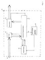
- Fig. 2 shows a schematic representation of the structure of an analysis device 12 according to the invention.
- the double arrows indicate the flow of data, while single arrows indicate information which has been determined from the data.
- the implementation possibilities for such devices are well known to the person skilled in the art and will therefore not be described further here.
- the determined current state is communicated to a central control unit 14 of the analysis device 12.
- the central control unit 14 configures a filter 16. More specifically, the filter 16 is configured to search for data corresponding to the conditions that are possible based on the detected current state.
- the central control unit 14 applies a signal 18 to a module 20 in which a software description of the state machine used is stored.
- the signal 18 corresponds to the current state of the state machine and causes an updating of a loadable hardware circuit 22 as already mentioned in connection with FIG.
- the replica 22 includes only a portion of the state machine relevant to the current state of the state machine, i. in particular the possible subsequent conditions and subsequent states based on the current state.
- the analyzer 12 operates as follows. According to the configuration of the filter 16 10 data are filtered out of the incoming data and sent to the central Control unit 14 passed. This passes the data to the replica 22 of the relevant part of the state machine, from where the data modified by the replica 22 is returned to the central control unit 14 again. This data is passed to a decoder 24, which provides the decoded data 26 at the output of the analyzer 12. The decoded data is additionally supplied by the decoder 24 to the central control unit 14, which determines therefrom the new current state of the state machine. In response to this new current state, on the one hand, the filter 16 is reconfigured, on the other hand the replica 22 is updated via the block 20.
- the components of the analyzer 12 are chosen such that the analysis, i. the provision of the result data 26 can take place in real time.
- the analyzer is particularly designed for analysis of the protocol layer that lies between the data link layer and the presentation layer.
- the entire analyzer 12 is implemented on a chip, and a protocol tester containing an analyzer 12 is implemented as a hand-held device.
Landscapes
- Engineering & Computer Science (AREA)
- Computer Security & Cryptography (AREA)
- Computer Networks & Wireless Communication (AREA)
- Signal Processing (AREA)
- Maintenance And Management Of Digital Transmission (AREA)
- Computer And Data Communications (AREA)
- Communication Control (AREA)
Description
- Die vorliegende Erfindung betrifft ein Verfahren und eine Vorrichtung zur Analyse von Daten, deren Abfolge durch eine Zustandsmaschine beschreibbar ist.
- Digitale Daten werden in einem Netzwerk gewöhnlich nach vorgegebenen Regeln übertragen. Eine Ausprägung derartiger Regeln sind sogenannte Protokolle. Protokolle können in Form von SDL-Diagrammen bzw. als Zustandsmaschinen beschrieben werden. Ein Teilnehmer an der Datenübertragung befindet sich demnach immer in einem bestimmten Zustand der Zustandsmaschine, ausgehend von dem er bei Vorliegen einer bestimmten Bedingung bzw. bei Vorliegen bestimmter Bedingungen in einen anderen Zustand wechseln kann.
- Fig. 1 zeigt zur Erläuterung ein einfaches Beispiel einer Zustandsmaschine. Es wird angenommen, der betrachtete Telekommunikationsteilnehmer befindet sich zunächst im Zustand A. Von diesem Zustand A kann er sich bei Vorliegen der Bedingung a in den Zustand C verändern. Bei Vorliegen der Bedingung b kann er sich in den Zustand B verändern. Ausgehend vom Zustand C kann er sich bei Vorliegen der Bedingung c in den Zustand E, bei Vorliegen der Bedingung d in den Zustand D verändern. Ausgehend vom Zustand E kann er sich bei Vorliegen der Bedingung g in den Zustand B, bei Vorliegen der Bedingung h in den Zustand G verändern, usw..
- Für die Analyse von Netzwerken im Hinblick auf Übertragungsfehler, Störungen und dergleichen werden häufig sogenannte Protokolltester eingesetzt. Ein Protokolltester muß daher ausgelegt sein, die übertragenen Daten zu analysieren. Gemäß einem ersten Stand der Technik findet diese Analyse im Off-Line-Betrieb statt, d.h. die übertragenen Daten werden zunächst in einen Speicher geladen und anschließend mittels Software-Suchroutinen ausgefiltert. Je nach den aufgefundenen Daten können schrittweise weitere Datenfragmente aus der Gesamtmenge der Daten gesucht und analysiert werden. Der Nachteil dieser Vorgehensweise liegt darin, daß hierdurch keine Analyse in Echtzeit ermöglicht wird. Aus einer unverhältnismäßig großen gespeicherten Datenmenge müssen die relevanten Daten zeitaufwendig aussortiert werden. Aus der US 5,850,388, deren Offenbarung durch diese Bezugnahme in den Offenbarungsgehalt der vorliegenden Anmeldung aufgenommen wird, ist eine andere Vorgehensweise bekannt. Um Daten in Echtzeit analysieren zu können, ist der dort beschriebene Protokolltester mit mehreren RISC (Reduced Instruction Set Computer) Prozessoren versehen und verfügt weiterhin über Hardware-Filter, um aus den eingehenden Daten Bit-Sequenzen auszufiltern, die von einem Benutzer zuvor spezifiziert wurden.
- Der Nachteil eines Protokolltesters gemäß der US 5,850,388 besteht darin, daß damit ein gewaltiger Aufwand an Hardware einhergeht, der sich nicht nur in den Kosten niederschlägt, sondern auch in Gewicht und damit Handlichkeit des Geräts.
- Der von Absillis und Goossens M. geschriebene Artikel "Advanced Protocol Analysers" offenbart eine Vorrichtung zur Analyse von Daten gemäss dem Oberbegriff des Anspruch 7.
- Die Aufgabe der vorliegenden Erfindung besteht daher darin, ein Verfahren bzw. eine Vorrichtung zur Analyse von Daten der eingangs genannten Art vorzuschlagen, das ebenfalls eine Analyse in Echtzeit ermöglicht, jedoch einen deutlich reduzierten Aufwand an Hardware erfordert.
- Diese Aufgabe wird gelöst, durch ein Verfahren, mit den Merkmalen von Patentanspruch 1 sowie durch eine Vorrichtung mit den Merkmalen von Patentanspruch 7. Die abhängigen Ansprüche stellen verschiedene Ausführungsbeispiele vor.
- Die im nachfolgenden aufgeführten Vorteile gelten sowohl für das erfindungsgemäße Verfahren als auch für die erfindungsgemäße Vorrichtung, werden der Einfachheit halber jedoch am Bei-spiel des Verfahrens ausgeführt. Die Erfindung basiert auf der Erkenntnis, daß ausgehend von einem aktuellen Zustand innerhalb der Zustandsmaschine nur ein Teil aller Zustände der Zustandsmaschine als Folgezustand in Betracht kommen. Demnach ist es nicht nötig alle Zustände und alle Bedingungen in einer Hardwareschaltung nachzubilden, vielmehr genügt die Nachbildung einer Teilmenge der Zustände und Bedingungen der Zustandsmaschine, die ausgehend vom aktuellen Zustand der Zustandsmaschine im nächsten Schritt oder in den nächsten Schritten von Relevanz sein können. In Kenntnis des aktuellen Zustands wird dann die Nachbildung durch Laden mindestens eines weiteren Zustands und/oder mindestens einer weiteren Bedingung aktualisiert. In entsprechender Weise wird das Filter aktualisiert, insbesondere durch Laden von Bedingungen, die ausgehend vom aktuellen Zustand der Zustandsmaschine möglich sind. Durch das Aktualisieren der Nachbildung im Hinblick auf den aktuellen Zustand ist nur eine begrenzte Chip-Komplexität notwendig, da die Elemente der hardwaremäßigen Nachbildung der Zustandsmaschine nur temporär verfügbar sein müssen. Durch die Ladbarkeit der Hardware können in höchst flexibler Weise auch Kundenwünsche und Länderanpassungen berücksichtigt werden.
- Eine derartige Realisierung mit ladbarer Hardware ermöglicht, daß der gesamte Hardwareaufwand sehr niedrig gehalten werden kann. Dadurch lassen sich Protokolltester realisieren, die sich durch ihr geringes Gewicht sowie sehr gute Handhabbarkeit auszeichnen. Insbesondere lassen sich durch die erfindungsgemäße Lösung in der Hand haltbare Protokolltester realisieren.
- Im Rahmen der vorliegenden Erfindung kann die Zustandsmaschine einem Datenübertragungsprotokoll entsprechen. Für den Fall, daß das Protokoll gemäß dem OSI-Referenzmodell aufgebaut ist, läßt sich die erfindungsgemäße Analysevorrichtung besonders vorteilhaft einsetzen zur Analyse der zwischen der Datenverbindungsschicht und der Präsentationsschicht liegenden Protokollschicht.
- Besonders vorteilhaft ist es, auch das Filter als ladbare Hardwareschaltung zu realisieren, wobei vorgesehen werden kann, auch die Einstellung des Filters durch Laden weiterer oder geänderter Filterparameter in Abhängigkeit des ermittelten neuen aktuellen Zustands zu aktualisieren.
- Weitere vorteilhafte Weiterbildungen der Erfindung können den Unteransprüchen entnommen werden. Ein Ausführungsbeispiel der Erfindung wird im Folgenden unter Hinweis auf die beigefügten Zeichnungen näher beschrieben. Es stellen dar:
- Fig. 1
- in schematischer Darstellung ein einfaches Beispiel einer Zustandsmaschine; und
- Fig. 2
- in Blockschaltbilddarstellung den Aufbau einer erfindungsgemäßen Analysevorrichtung.
- Fig. 1 zeigt in schematischer Darstellung den Aufbau eines Protokolls anhand einer Zustandsmaschine. In diesem einfachen Beispiel zeigen die Kreise Zustände an, die zwischen den Kreisen angeordneten Pfeile entsprechen einer oder mehreren Bedingungen, die erfüllt sein müssen, um vom Zustand am Ausgangspunkt des Pfeils zum Zustand an der Pfeilspitze zu wechseln. Bei der aus der US 5,850,388 bekannten Hardwarerealisierung wäre die gesamte Zustandsmaschine hardwaremäßig realisiert.
- Die erfindungsgemäße Lösung geht einen anderen Weg: Ausgehend von einem Zustand A zum Zeitpunkt t1 sind in der Hardwarenachbildung der Zustandsmaschine lediglich die Bedingungen a und b sowie die Zustände B und C geladen. Für den Fall, daß zum Zeitpunkt t2 die Bedingung a eintritt, findet ein Wechsel vom Zustand A in den Zustand C statt. Im Zustand C werden Nachbildungen der Bedingungen c und d sowie der Zustände D und E in die Hardwarenachbildung geladen. Sofern der Speicherbereich nicht ausreicht, werden die Nachbildungen der Bedingungen a und b sowie der Zustände A und B überschrieben. Für den Fall, daß zum Zeitpunkt t4 die Bedingung d eintritt, findet ein Wechsel vom Zustand C in den Zustand D statt. Dies hat zur Folge, daß Nachbildungen der Bedingungen e und f sowie der Zustände F und H in die Nachbildungsschaltung geladen werden. Sofern der Speicherbereich nicht ausreicht, werden im Hinblick auf den aktuellen Zustand zunächst nicht benötigte Bedingungen und Zustände überschrieben.
- Fig. 2 zeigt in schematischer Darstellung den Aufbau einer erfindungsgemäßen Analysevorrichtung 12. Durch die Doppelpfeile wird der Fluß von Daten gekennzeichnet, während Einfachpfeile Information kennzeichnen, die aus den Daten ermittelt wurde. Nicht dargestellt ist eine Vorrichtung zum Herstellen einer Synchronisation zwischen den eingehenden Daten 10 der Analysevorrichtung 12 und eine Vorrichtung zum Ermitteln des aktuellen Zustands der Zustandsmaschine. Die Realisierungsmöglichkeiten für derartige Vorrichtungen sind dem Fachmann hinlänglich bekannt und werden deshalb hier nicht weiter beschrieben. Der ermittelte aktuelle Zustand wird einer zentralen Steuereinheit 14 der Analysevorrichtung 12 mitgeteilt. Im Hinblick auf diesen aktuellen Zustand konfiguriert die zentrale Steuereinheit 14 ein Filter 16. Insbesondere wird das Filter 16 im Hinblick auf die Suche nach Daten konfiguriert, die den Bedingungen entsprechen, die ausgehend vom ermittelten aktuellen Zustand möglich sind. Weiterhin legt die zentrale Steuereinheit 14 ein Signal 18 an einen Baustein 20, in dem eine softwaremäßige Beschreibung der verwendeten Zustandsmaschine abgelegt ist. Das Signal 18 korrespondiert mit dem aktuellen Zustand der Zustandsmaschine und veranlaßt eine Aktualisierung einer ladbaren Hardwareschaltung 22 wie bereits im Zusammenhang mit Fig. 1 erwähnt. Die Nachbildung 22 umfaßt nur einen im Hinblick auf den aktuellen Zustand der Zustandsmaschine relevanten Teil der Zustandsmaschine, d.h. insbesondere die ausgehend vom aktuellen Zustand möglichen Folgebedingungen und Folgezustände.
- Nach dieser Initialisierung arbeitet die Analysevorrichtung 12 wie folgt. Entsprechend der Konfiguration des Filters 16 werden aus den eingehenden Daten 10 Daten ausgefiltert und an die zentrale Steuereinheit 14 geleitet. Diese leitet die Daten an die Nachbildung 22 des relevanten Teils der Zustandsmaschine, von wo aus die durch die Nachbildung 22 modifizierten Daten wieder an die zentrale Steuereinheit 14 zurückgeleitet werden. Diese Daten werden einem Dekodierer 24 zugeleitet, der die dekodierten Daten 26 am Ausgang der Analysevorrichtung 12 bereitstellt. Die dekodierten Daten werden vom Dekodierer 24 zusätzlich der zentralen Steuereinheit 14 zugeführt, welche daraus den neuen aktuellen Zustand der Zustandsmaschine ermittelt. In Abhängigkeit von diesem neuen aktuellen Zustand wird zum einen das Filter 16 neu konfiguriert, zum anderen die Nachbildung 22 über den Baustein 20 aktualisiert.
- Die Komponenten der Analysevorrichtung 12 sind derart gewählt, daß die Analyse, d.h. die Bereitstellung der Ergebnisdaten 26 in Echtzeit erfolgen kann.
- Für den Fall, daß das Protokoll gemäß dem OSI-Referenzmodell aufgebaut ist, ist die Analysevorrichtung insbesondere auf die Analyse der Protokollschicht ausgelegt, die zwischen der Datenverbindungsschicht und der Präsentationsschicht liegt. Die gesamte Analysevorrichtung 12 ist auf einem Chip implementiert und ein Protokolltester, der eine Analysevorrichtung 12 enthält, ist als ein in der Hand haltbares Gerät realisiert.
Claims (13)
- Verfahren zur Analyse von Daten, deren Abfolge durch eine Zustandsmaschine beschreibbar ist, mittels einer Analysevorrichtung folgende Schritte umfassend:a) Herstellen einer Synchronisation zwischen eingehenden Daten und Analysevorrichtung (12);b) Ermitteln des aktuellen Zustands der Zustandsmaschine;c) Konfigurieren eines Filters (16) der Analysevorrichtung (12) für die eingehenden Daten in Abhängigkeit des aktuellen Zustands;d) Zuführen der gefilterten Daten an eine Nachbildung (22) eines im Hinblick auf den aktuellen Zustand relevanten Teils der Zustandsmaschine, wobei die Nachbildung in der Analysevorrichtung dadurch realisiert ist, daß die Zustände und Bedingungen dieses Teils der Zustandsmaschine durch eine ladbare Hardwareschaltung repräsentiert werden;e) Ermitteln des neuen aktuellen Zustands der Zustandsmaschine durch Auswerten des Ergebnisses der Nachbildung (22);f) Aktualisieren der Nachbildung (22) durch Laden mindestens eines weiteren Zustands und/oder einer weiteren Bedingung in die ladbare Hardwareschaltung in Abhängigkeit des ermittelten neuen aktuellen Zustands.
- Verfahren nach Anspruch 1,
dadurch gekennzeichnet,
daß in Schritt b) das Filter (16) im Hinblick auf die Suche nach Daten konfiguriert wird, die den Bedingungen entsprechen, die ausgehend vom aktuellen Zustand möglich sind. - Verfahren nach einem der Ansprüche 1 oder 2,
dadurch gekennzeichnet,
daß die Zustandsmaschine einem Datenübertragungs-Protokoll entspricht. - Verfahren nach Anspruch 3,
dadurch gekennzeichnet,
daß das Protokoll gemäß dem OSI-Referenzmodell aufgebaut ist und mit der Analysevorrichtung die zwischen der Datenverbindungsschicht und der Präsentationsschicht liegende Protokollschicht analysiert wird. - Verfahren nach einem der vorhergehenden Ansprüche,
dadurch gekennzeichnet,
daß das Filter (16) eine ladbare Hardwareschaltung umfaßt, wobei Schritt f) weiterhin umfaßt:Aktualisieren der Einstellung des Filters (16) durch Laden weiterer oder geänderter Filterparameter in Abhängigkeit des ermittelten neuen aktuellen Zustands. - Verfahren nach einem der vorhergehenden Ansprüche,
dadurch gekennzeichnet,
daß die Analyse in Echtzeit durchgeführt wird. - Vorrichtung zur Analyse von Daten, deren Abfolge durch eine Zustandsmaschine beschreibbar ist, umfassend:- eine Synchronisiervorrichtung zum Herstellen einer Synchronisation zwischen eingehenden Daten und der Analysevorrichtung;- einer Vorrichtung zum Ermitteln des aktuellen Zustands der Zustandsmaschine;
wobei die Vorrichtung dadurch gekennzeichnet ist, daß sie auch die folgenden Komponenten enthält;- einen Filter (16), das im Hinblick auf den aktuellen Zustand der Zustandsmaschine konfigurierbar ist;- eine ladbare Hardwareschaltung (22), mit der im Hinblick auf einen aktuellen Zustand der Zustandsmaschine Zustände und Bedingungen eines relevanten Teils der Zustandsmaschine nachbildbar sind;- eine Vorrichtung (14) zum Ermitteln eines neuen aktuellen Zustands der Zustandsmaschine unter Verwendung des Ergebnisses der ladbaren Hardwareschaltung (22);- eine Vorrichtung (14, 20) zum Aktualisieren der ladbaren Hardwareschaltung (22) durch Laden mindestens eines weiteren Zustands und/oder einer weiteren Bedingung in die ladbare Hardwareschaltung (22) in Abhängigkeit des Ergebnisses der Ermittlungsvorrichtung (14, 24). - Vorrichtung nach Anspruch 7,
dadurch gekennzeichnet,
daß das Filter (16) im Hinblick auf die Suche nach Daten konfigurierbar ist, die den Bedingungen entsprechen, die ausgehend vom ermittelten aktuellen Zustand möglich sind. - Vorrichtung nach einem der Ansprüche 7 oder 8,
dadurch gekennzeichnet,
daß die Zustandsmaschine einem Datenübertragungs-Protokoll entspricht. - Vorrichtung nach Anspruch 9,
dadurch gekennzeichnet,
daß das Protokoll gemäß dem OSI-Referenzmodell aufgebaut ist und mit der Analysevorrichtung die zwischen der Datenverbindungsschicht und der Präsentationsschicht liegende Protokollschicht analysierbar ist. - Vorrichtung nach einem der Ansprüche 7 bis 10,
dadurch gekennzeichnet,
daß das Filter (16) eine ladbare Hardwareschaltung umfaßt, die mittels der Aktualisierungsvorrichtung (14, 20) durch Laden weiterer oder geänderter Filterparameter in Abhängigkeit des ermittelten neuen aktuellen Zustands änderbar ist. - Vorrichtung nach einem der Ansprüche 7 bis 11,
dadurch gekennzeichnet,
daß die die Bauteile der Analysevorrichtung (12) derart ausgelegt sind, daß die Analyse in Echtzeit durchführbar ist. - Protokolltester mit einer Vorrichtung nach einem der Ansprüche 7 bis 12.
Priority Applications (4)
| Application Number | Priority Date | Filing Date | Title |
|---|---|---|---|
| DE50013051T DE50013051D1 (de) | 2000-04-14 | 2000-04-14 | Verfahren und Vorrichtung zur Analyse von Daten |
| EP00108276A EP1146690B1 (de) | 2000-04-14 | 2000-04-14 | Verfahren und Vorrichtung zur Analyse von Daten |
| US09/795,867 US7024349B2 (en) | 2000-04-14 | 2001-02-27 | Method and device for analyzing data |
| JP2001111666A JP3682414B2 (ja) | 2000-04-14 | 2001-04-10 | データ分析方法及び装置 |
Applications Claiming Priority (1)
| Application Number | Priority Date | Filing Date | Title |
|---|---|---|---|
| EP00108276A EP1146690B1 (de) | 2000-04-14 | 2000-04-14 | Verfahren und Vorrichtung zur Analyse von Daten |
Publications (2)
| Publication Number | Publication Date |
|---|---|
| EP1146690A1 EP1146690A1 (de) | 2001-10-17 |
| EP1146690B1 true EP1146690B1 (de) | 2006-06-21 |
Family
ID=8168485
Family Applications (1)
| Application Number | Title | Priority Date | Filing Date |
|---|---|---|---|
| EP00108276A Expired - Lifetime EP1146690B1 (de) | 2000-04-14 | 2000-04-14 | Verfahren und Vorrichtung zur Analyse von Daten |
Country Status (4)
| Country | Link |
|---|---|
| US (1) | US7024349B2 (de) |
| EP (1) | EP1146690B1 (de) |
| JP (1) | JP3682414B2 (de) |
| DE (1) | DE50013051D1 (de) |
Families Citing this family (5)
| Publication number | Priority date | Publication date | Assignee | Title |
|---|---|---|---|---|
| US6985968B1 (en) * | 2001-05-11 | 2006-01-10 | Alcatel | State machine architecture partitionable into control and data planes |
| EP1347599B1 (de) | 2002-03-22 | 2005-07-20 | Tektronix Berlin GmbH & Co. KG | Verfahren und Protokolltester zum Dekodieren gemäss einer Protokollbeschreibung kodierter Daten |
| US7529979B2 (en) * | 2003-12-12 | 2009-05-05 | International Business Machines Corporation | Hardware/software based indirect time stamping methodology for proactive hardware/software event detection and control |
| CN100505752C (zh) * | 2005-01-21 | 2009-06-24 | 华为技术有限公司 | 文本编码类协议通用解析器 |
| KR102162024B1 (ko) * | 2018-12-27 | 2020-10-06 | 한국과학기술원 | 동작 모델링 및 비교 분석을 이용한 이동통신네트워크의 이상 진단 장치 및 그 방법 |
Family Cites Families (13)
| Publication number | Priority date | Publication date | Assignee | Title |
|---|---|---|---|---|
| US3826908A (en) * | 1973-02-05 | 1974-07-30 | Paradyne Corp | Data telecommunications analyzer |
| US4125763A (en) * | 1977-07-15 | 1978-11-14 | Fluke Trendar Corporation | Automatic tester for microprocessor board |
| US4483002A (en) * | 1982-04-19 | 1984-11-13 | International Business Machines Corporation | Digital device testing apparatus and method |
| EP0474932A1 (de) * | 1990-09-13 | 1992-03-18 | Hewlett-Packard Company | Fehleranalysator für Netzwerk |
| US5375126B1 (en) * | 1991-04-09 | 1999-06-22 | Hekimian Laboratories Inc | Integrated logical and physical fault diagnosis in data transmission systems |
| US5287506A (en) * | 1991-10-17 | 1994-02-15 | Hewlett-Packard Company | Token ring network protocol analyzer |
| ATE153786T1 (de) * | 1993-09-28 | 1997-06-15 | Siemens Ag | Tracer-system zur fehleranalyse in laufenden realzeitsystemen |
| US5579476A (en) * | 1993-10-19 | 1996-11-26 | Industrial Technology Research Institute | Automatic test environment for communications protocol software |
| US5745777A (en) * | 1994-05-10 | 1998-04-28 | Seiko Communications Holding N.V. | Analyzer for frequency modulated signals |
| GB9512303D0 (en) * | 1995-06-16 | 1995-08-16 | Assessment Services Ltd | Improvements in or relating to data analysers |
| US6618393B1 (en) * | 1998-08-26 | 2003-09-09 | 3Com Corporation | Method and apparatus for transparent support of network protocols with header translation |
| US5774695A (en) * | 1996-03-22 | 1998-06-30 | Ericsson Inc. | Protocol interface gateway and method of connecting an emulator to a network |
| US5850388A (en) * | 1996-08-02 | 1998-12-15 | Wandel & Goltermann Technologies, Inc. | Protocol analyzer for monitoring digital transmission networks |
-
2000
- 2000-04-14 DE DE50013051T patent/DE50013051D1/de not_active Expired - Lifetime
- 2000-04-14 EP EP00108276A patent/EP1146690B1/de not_active Expired - Lifetime
-
2001
- 2001-02-27 US US09/795,867 patent/US7024349B2/en not_active Expired - Fee Related
- 2001-04-10 JP JP2001111666A patent/JP3682414B2/ja not_active Expired - Fee Related
Also Published As
| Publication number | Publication date |
|---|---|
| JP2002016662A (ja) | 2002-01-18 |
| JP3682414B2 (ja) | 2005-08-10 |
| US20010032069A1 (en) | 2001-10-18 |
| US7024349B2 (en) | 2006-04-04 |
| EP1146690A1 (de) | 2001-10-17 |
| DE50013051D1 (de) | 2006-08-03 |
Similar Documents
| Publication | Publication Date | Title |
|---|---|---|
| DE68924744T2 (de) | Kontaktstiftelektronik-Einrichtung mit Phasenjustierung für einen IC-Tester und Verfahren zur Phasenjustierung. | |
| DE602004011445T2 (de) | FEC-Dekodierung mit dynamischen Parametern | |
| DE60314915T2 (de) | Kommunikationschnittstelle für diagnoseschaltungen einer integrierten schaltung | |
| DE69131007T2 (de) | Anruffortschreitungsdekodierer für mehrfach getaktete Töne auf Telefonleitungen | |
| DE102008010290A1 (de) | Verfahren zum Testen eines Mobilfunkgeräts | |
| EP2160908B1 (de) | Verfahren zum testen eines mobilfunkgeräts | |
| DE2658611A1 (de) | Vorrichtung zur erzeugung und zum empfang von digitalwoertern | |
| DE3341766C2 (de) | Verfahren und Vorrichtung zur Identifikation von Daten | |
| DE2515297A1 (de) | Pruefsystem fuer logische netzwerke mit simulatororientiertem fehlerpruefgenerator | |
| DE19742088A1 (de) | Verfahren zur Initialisierung eines an einen Diagnose-Bus angeschlossenen Steuergeräts | |
| DE3702408A1 (de) | Verfahren und pruefvorrichtung zum pruefen einer integrierten schaltungsanordnung | |
| EP1347599B1 (de) | Verfahren und Protokolltester zum Dekodieren gemäss einer Protokollbeschreibung kodierter Daten | |
| DE69721395T2 (de) | Verfahren und Vorrichtung zur Anpassung von Modellen zur Sprecherverifikation | |
| EP0370327B1 (de) | Optimierer für ein parameterabhängiges Netzwerksystem | |
| EP1128602A1 (de) | Vorrichtung zum Aufbau eines Protokoll-Stacks und zugehöriges Verfahren | |
| EP1038221B1 (de) | Verfahren zur überprüfung der pfadüberdeckung bei software-tests | |
| DE60217729T2 (de) | Verfahren zum erkennen eines elektronischen geräts in einem mehrfachsteuersystem | |
| EP1146690A1 (de) | Verfahren und Vorrichtung zur Analyse von Daten | |
| DE4233837A1 (de) | Rechenanlage | |
| DE3611772A1 (de) | Verfahren zum fixieren eines momentanen messwertes | |
| DE112012006601T5 (de) | Hilfsgerät, Hilfsverfahren und Programm | |
| DE60100060T2 (de) | Synchronisation eines Datenstromes | |
| DE4426739C2 (de) | Testverfahren sowie Einrichtung zum Erzeugen von Test-Fällen, Testeinrichtung und Programm-Modul dafür | |
| DE3437906C2 (de) | ||
| DE60101332T2 (de) | Verfahren zum automatischen steuern von leistungsmessungen in einem netzwerk, steuervorrichtung zur leistungsverwaltung und system zur leistungsverwaltung |
Legal Events
| Date | Code | Title | Description |
|---|---|---|---|
| PUAI | Public reference made under article 153(3) epc to a published international application that has entered the european phase |
Free format text: ORIGINAL CODE: 0009012 |
|
| AK | Designated contracting states |
Kind code of ref document: A1 Designated state(s): DE FR GB IT Kind code of ref document: A1 Designated state(s): AT BE CH CY DE DK ES FI FR GB GR IE IT LI LU MC NL PT SE |
|
| AX | Request for extension of the european patent |
Free format text: AL;LT;LV;MK;RO;SI |
|
| 17P | Request for examination filed |
Effective date: 20011016 |
|
| AKX | Designation fees paid |
Free format text: DE FR GB IT |
|
| RAP1 | Party data changed (applicant data changed or rights of an application transferred) |
Owner name: TEKTRONIX BERLIN GMBH & CO. KG |
|
| GRAP | Despatch of communication of intention to grant a patent |
Free format text: ORIGINAL CODE: EPIDOSNIGR1 |
|
| GRAS | Grant fee paid |
Free format text: ORIGINAL CODE: EPIDOSNIGR3 |
|
| GRAA | (expected) grant |
Free format text: ORIGINAL CODE: 0009210 |
|
| AK | Designated contracting states |
Kind code of ref document: B1 Designated state(s): DE FR GB IT |
|
| PG25 | Lapsed in a contracting state [announced via postgrant information from national office to epo] |
Ref country code: IT Free format text: LAPSE BECAUSE OF FAILURE TO SUBMIT A TRANSLATION OF THE DESCRIPTION OR TO PAY THE FEE WITHIN THE PRESCRIBED TIME-LIMIT;WARNING: LAPSES OF ITALIAN PATENTS WITH EFFECTIVE DATE BEFORE 2007 MAY HAVE OCCURRED AT ANY TIME BEFORE 2007. THE CORRECT EFFECTIVE DATE MAY BE DIFFERENT FROM THE ONE RECORDED. Effective date: 20060621 |
|
| REG | Reference to a national code |
Ref country code: GB Ref legal event code: FG4D Free format text: NOT ENGLISH |
|
| REF | Corresponds to: |
Ref document number: 50013051 Country of ref document: DE Date of ref document: 20060803 Kind code of ref document: P |
|
| GBT | Gb: translation of ep patent filed (gb section 77(6)(a)/1977) |
Effective date: 20060923 |
|
| ET | Fr: translation filed | ||
| PLBE | No opposition filed within time limit |
Free format text: ORIGINAL CODE: 0009261 |
|
| STAA | Information on the status of an ep patent application or granted ep patent |
Free format text: STATUS: NO OPPOSITION FILED WITHIN TIME LIMIT |
|
| 26N | No opposition filed |
Effective date: 20070322 |
|
| PGFP | Annual fee paid to national office [announced via postgrant information from national office to epo] |
Ref country code: FR Payment date: 20100506 Year of fee payment: 11 |
|
| PGFP | Annual fee paid to national office [announced via postgrant information from national office to epo] |
Ref country code: IT Payment date: 20100427 Year of fee payment: 11 Ref country code: DE Payment date: 20100423 Year of fee payment: 11 |
|
| PGFP | Annual fee paid to national office [announced via postgrant information from national office to epo] |
Ref country code: GB Payment date: 20100420 Year of fee payment: 11 |
|
| REG | Reference to a national code |
Ref country code: DE Ref legal event code: R119 Ref document number: 50013051 Country of ref document: DE |
|
| REG | Reference to a national code |
Ref country code: DE Ref legal event code: R119 Ref document number: 50013051 Country of ref document: DE |
|
| GBPC | Gb: european patent ceased through non-payment of renewal fee |
Effective date: 20110414 |
|
| REG | Reference to a national code |
Ref country code: FR Ref legal event code: ST Effective date: 20111230 |
|
| PG25 | Lapsed in a contracting state [announced via postgrant information from national office to epo] |
Ref country code: FR Free format text: LAPSE BECAUSE OF NON-PAYMENT OF DUE FEES Effective date: 20110502 |
|
| PG25 | Lapsed in a contracting state [announced via postgrant information from national office to epo] |
Ref country code: GB Free format text: LAPSE BECAUSE OF NON-PAYMENT OF DUE FEES Effective date: 20110414 Ref country code: IT Free format text: LAPSE BECAUSE OF NON-PAYMENT OF DUE FEES Effective date: 20110414 |
|
| PG25 | Lapsed in a contracting state [announced via postgrant information from national office to epo] |
Ref country code: DE Free format text: LAPSE BECAUSE OF NON-PAYMENT OF DUE FEES Effective date: 20111031 |