EP1146292B1 - Air generating device having controlled temperature in particular for livestock breeding - Google Patents
Air generating device having controlled temperature in particular for livestock breeding Download PDFInfo
- Publication number
- EP1146292B1 EP1146292B1 EP20010400824 EP01400824A EP1146292B1 EP 1146292 B1 EP1146292 B1 EP 1146292B1 EP 20010400824 EP20010400824 EP 20010400824 EP 01400824 A EP01400824 A EP 01400824A EP 1146292 B1 EP1146292 B1 EP 1146292B1
- Authority
- EP
- European Patent Office
- Prior art keywords
- air
- burner
- generator
- premises
- burners
- Prior art date
- Legal status (The legal status is an assumption and is not a legal conclusion. Google has not performed a legal analysis and makes no representation as to the accuracy of the status listed.)
- Expired - Lifetime
Links
- 244000144972 livestock Species 0.000 title description 5
- 238000009395 breeding Methods 0.000 title 1
- 230000001488 breeding effect Effects 0.000 title 1
- 238000010438 heat treatment Methods 0.000 claims description 12
- 238000009423 ventilation Methods 0.000 claims description 11
- 239000000203 mixture Substances 0.000 claims description 10
- 238000002485 combustion reaction Methods 0.000 claims description 6
- 230000006698 induction Effects 0.000 claims description 3
- 229910000838 Al alloy Inorganic materials 0.000 claims description 2
- 229920000914 Metallic fiber Polymers 0.000 claims description 2
- -1 iron-chromium-aluminium Chemical compound 0.000 claims description 2
- 230000001276 controlling effect Effects 0.000 claims 2
- 230000000384 rearing effect Effects 0.000 claims 1
- 230000001105 regulatory effect Effects 0.000 claims 1
- 239000007789 gas Substances 0.000 description 18
- 238000010790 dilution Methods 0.000 description 6
- 239000012895 dilution Substances 0.000 description 6
- 210000000056 organ Anatomy 0.000 description 6
- 238000005265 energy consumption Methods 0.000 description 5
- IJGRMHOSHXDMSA-UHFFFAOYSA-N Atomic nitrogen Chemical compound N#N IJGRMHOSHXDMSA-UHFFFAOYSA-N 0.000 description 4
- 238000007789 sealing Methods 0.000 description 2
- 210000003462 vein Anatomy 0.000 description 2
- OKTJSMMVPCPJKN-UHFFFAOYSA-N Carbon Chemical compound [C] OKTJSMMVPCPJKN-UHFFFAOYSA-N 0.000 description 1
- UGFAIRIUMAVXCW-UHFFFAOYSA-N Carbon monoxide Chemical class [O+]#[C-] UGFAIRIUMAVXCW-UHFFFAOYSA-N 0.000 description 1
- 238000007664 blowing Methods 0.000 description 1
- 229910052799 carbon Inorganic materials 0.000 description 1
- 229910002090 carbon oxide Inorganic materials 0.000 description 1
- 230000001419 dependent effect Effects 0.000 description 1
- 238000006073 displacement reaction Methods 0.000 description 1
- 239000000835 fiber Substances 0.000 description 1
- 238000009434 installation Methods 0.000 description 1
- 238000004519 manufacturing process Methods 0.000 description 1
- 229910052751 metal Inorganic materials 0.000 description 1
- 239000002184 metal Substances 0.000 description 1
- 238000000034 method Methods 0.000 description 1
- 238000012544 monitoring process Methods 0.000 description 1
- 229910052757 nitrogen Inorganic materials 0.000 description 1
- MWUXSHHQAYIFBG-UHFFFAOYSA-N nitrogen oxide Inorganic materials O=[N] MWUXSHHQAYIFBG-UHFFFAOYSA-N 0.000 description 1
- 230000002093 peripheral effect Effects 0.000 description 1
- 229910052761 rare earth metal Inorganic materials 0.000 description 1
- 150000002910 rare earth metals Chemical class 0.000 description 1
- 238000003303 reheating Methods 0.000 description 1
- 230000001360 synchronised effect Effects 0.000 description 1
- 238000011144 upstream manufacturing Methods 0.000 description 1
- 229910052727 yttrium Inorganic materials 0.000 description 1
- VWQVUPCCIRVNHF-UHFFFAOYSA-N yttrium atom Chemical compound [Y] VWQVUPCCIRVNHF-UHFFFAOYSA-N 0.000 description 1
Images

Classifications
-
- F—MECHANICAL ENGINEERING; LIGHTING; HEATING; WEAPONS; BLASTING
- F24—HEATING; RANGES; VENTILATING
- F24F—AIR-CONDITIONING; AIR-HUMIDIFICATION; VENTILATION; USE OF AIR CURRENTS FOR SCREENING
- F24F3/00—Air-conditioning systems in which conditioned primary air is supplied from one or more central stations to distributing units in the rooms or spaces where it may receive secondary treatment; Apparatus specially designed for such systems
- F24F3/044—Systems in which all treatment is given in the central station, i.e. all-air systems
Definitions
- the present invention relates to an air generator with controlled temperature, especially for livestock buildings or industrial, this generator consisting of a box housing at least one burner and at least one fan dilution to propel in a room, at temperature desired, the air circulating in said box.
- These generators are today generally exclusively used as heating device. They usually have a only source of air supply constituted either by outside air or fresh air, either from local air or recycled air.
- the use of air room allows a reduction in energy consumption, especially in winter because it is cheaper to heat air close to room temperature than air outdoor temperature dependent on conditions climate.
- the air used is air of the room, the generator is generally placed at inside the building. This results in risks fire.
- the composition of this air requires a parallel installation of significant ventilation.
- the burners used in this type of generator are usually burners atmospheres whose power range is reduced.
- the generator operation is discontinuous in this case and consists of a succession of judgments and implementations walking requiring increased monitoring and increasing energy consumption.
- the generator supply air is constituted by the outside air
- consumption energy is important and humidity problems can arise especially in winter when the air is more dry.
- this generator can, in certain conditions, partially meet the requirements of ventilation.
- the temperature controlled air generator has a recycled air inlet shown in (80) in the figures, closable by means of obturating members represented in (84) and (90), an external air inlet shown in (62), closable by means of shutter members shown in (86) and (90) and an external air inlet shown in (76) for the supply of fresh air to the burner.
- the cooperation of air inlet shutters (80) and (62) makes it possible to obtain, inside the box, a flow air consisting of a mixture of fresh air flow and flow recycled.
- each air inlet is closed by means of a sealing member which is attached thereto clean
- these shutter members can be controlled by synchronous operation to allow opening of an air inlet parallel to the closure of another air inlet.
- the very arrangement of the air inlets means that to this particular conception of the shutter members. It is the same in the generator described in the patent US Patent 5,290,188. Indeed, this generator comprises at the level from the box an external air inlet shown in (53) and closable by means of closing members, an outside air inlet (40) intended to supply the burner and a recirculated air inlet (69) closed by means a shutter member (67).
- An object of the present invention is to provide a temperature controlled air generator whose design simplified allows reduced energy consumption while by authorizing one use of this generator at a time as a heating and ventilation device.
- Another object of the present invention is to provide a temperature controlled air generator whose design makes it possible to comply as much as possible with the heating instructions and ventilation of the room.
- the invention relates to an air generator with temperature controlled especially for livestock building or industrial, this generator consisting of a box housing at least one burner and at least one fan dilution to propel in a room, at temperature desired, the air circulating in said box, this generator comprising at least two sources of air supply, one of recycled air drawn from the room to be heated, the other fresh air from outside the room, the generator also includes a mixer controllable airflow to obtain a flow in the box fresh air or a recirculated air stream or a mixture of air fresh and recycled air depending on variations in climatic conditions and / or ventilation needs of occupants of the room, this mixer tap consists of a shutter mobile located at the confluence of the supply veins in recirculated and fresh air to regulate the flow said air supply sources.
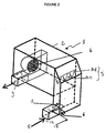
- the temperature-controlled air generator shown under the general reference 1, object of the invention, is more particularly intended to be used in the context livestock buildings or industrial buildings.
- This air generator can be placed indifferently to outside or inside the room to be heated.
- This generator 1 is constituted, in a manner known per se, a box 2, generally metallic, housing at least a gas burner 3 and at least one fan 4 of dilution.
- This dilution fan 4 arranged upstream or downstream of the burner 3, is intended to propel, by suction or blowing, the air circulating in said box in a room at a desired temperature.
- box 2 is equipped with a hot air outlet shown at 9 in the figures.
- the air generator conventionally comprises at least one air inlet.
- the flow of the dilution fan is chosen depending on the volume of the room to be heated to allow heating of the entire room volume.
- the generator 1 has at least two sources of air supply, one, shown in 5 in the figures, of recycled air drawn in the room to be heated, the other, shown in 6 aux figures, fresh air from outside the room.
- the fresh air inlet 6 thus consists of an opening formed in the bottom wall or in a side wall of the generator housing positioned outside the building, while the inlet 5 for recycled air is formed by a tube connected to a side wall of the generator of such so that the bottom wall of the tube is arranged coplanar at the bottom wall of the housing and that the end of the tube opens directly above the opening defining the entrance 6 fresh air.
- This generator 1 also includes a ventilation mixer 7 controllable to obtain an air flow in box 2 fresh air or a recirculated air stream or a mixture of fresh air and air recycled according to variations in conditions and / or occupants' ventilation needs from the local. So, thanks to such a generator, it is possible obtain 0 to 100% fresh air flow or 0 to 100% recirculated air flow or a mixture of fresh air and air recycled in any proportions determined by operator based on parameters chosen by this last, especially depending on weather conditions and / or the ventilation needs of the occupants of the premises.
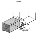
- this mixer tap consists of a single movable flap 7 arranged at the confluence of the recycled air supply streams and in fresh air to regulate the flow of said sources 5, 6 air supply.
- the flap 7 is thus arranged at the intersection of inputs 5, 6 delimiting in the housing of the generator of the perpendicular opening planes between them.
- the plans for opening the inputs 5, 6 in the housing of the generator thus form a dihedral, the flap 7, of preferably housed inside the volume of the dihedral, being hingedly connected to the dihedral edge, this edge constituting the pivot axis of the flap 7.
- the pivot axis of flap 7 is horizontal.
- This component 7 can be moved manually using a pull tab 10 allowing the flap to pivot around an axis 11 of rotation, as shown in Figure 3, or else be motorized by a servomotor controlled by a PLC.
- the arrangement of this component at the confluence of veins allows this component to be used as a obturation member unique for the two air intakes 5, 6 and to simplify its command on the move because naturally, when it closes a certain percentage entry, it opens the other entry in the same percentage at the same time.
- the temperature controlled air generator can both perform the functions of a heater and fan while maintaining energy consumption at a reasonable level consistent with that of a generator of air used exclusively as a heating device.
- the burner 3, housed in the box of the generator may be of the gas induction by air type.
- This type of burner makes it possible in particular to obtain a range of extended heating power setting.
- this heating power adjustment range includes values can vary from 1 to 10 while the burners classical atmospheres have a power of heaters can vary within a range of 1 to 3.
- these air induction type burners are safer because they don't require a power supply in pressurized gas.
- the gas is introduced into the air in function of the air flow, this air flow being obtained at by means of a fan supplied with primary air generally corresponding to outside air.
- combustion obtained by means of this type of burner is of better quality, in particular in terms of quantity of nitrogen and carbon oxides products.
- This type of burner can also be used with a combustion support, also called flame catcher, of the type consisting of a set of fibers metal formed from an iron-chromium-aluminum alloy supplemented with at least one rare earth such as yttrium.
- a combustion support also called flame catcher
- a combustion support of the type constituted by metallic fibers allows to increase so considerable range of power adjustment heated. This gives a heating power which can vary from 1 to 10 and not more than 1 to 3 as in the state of the technique. This results in a decrease in the frequency of switching between the on and off positions of the burner. This results for the user in an absence feeling of discomfort which was due to the inertia of conventional burners.
- each link is carried out according to a predetermined order depending on the relative positioning burners on the common gas supply line so as to allow automatic ignition of the flame of a BE slave burner by contact of the mixture air / gas expelled from said burner with the flame of a burner master BM or adjacent slave BE.
- the shutter with controlled opening / closing of the connection between a master or slave burner and the source gas supply can affect a lot of forms. It can thus be made up of a single organ common to all burners.
- this organ shutter is mounted in sliding sliding contact support inside the gas supply line and is axially movable inside said pipe for release and obstruct successively during its moving the connection port of a burner to the gas supply line.
- the displacement of this the shutter member can be operated manually or by means of a driving organ.
- This obturation member can by example consisting of a piston or a fitted drawer at least one external peripheral seal.
- the obturation member can also be made up of a pre-calibrated closure member, such as a valve loaded by an elastic return means, the opening or respectively the closing is a function of the pressure gas prevailing inside the supply line in gas.
- the tare weight of each sealing member is chosen depending on the relative positioning of the burner at which said organ relates.
- the loaded shutters by an elastic return means, such as a spring, are arranged respectively inside the pipe gas supply, between the gas supply source line gas and the burner to which they relate.
Landscapes
- Engineering & Computer Science (AREA)
- Chemical & Material Sciences (AREA)
- Combustion & Propulsion (AREA)
- Mechanical Engineering (AREA)
- General Engineering & Computer Science (AREA)
- Regulation And Control Of Combustion (AREA)
- Housing For Livestock And Birds (AREA)
- Ventilation (AREA)
Description
La présente invention concerne un générateur d'air à température contrôlée, notamment pour bâtiments d'élevage ou industriel, ce générateur étant constitué d'un caisson logeant au moins un brûleur et au moins un ventilateur de dilution pour propulser dans un local, à température voulue, l'air circulant dans ledit caisson.The present invention relates to an air generator with controlled temperature, especially for livestock buildings or industrial, this generator consisting of a box housing at least one burner and at least one fan dilution to propel in a room, at temperature desired, the air circulating in said box.
Les générateurs d'air chaud utilisés pour le réchauffage de l'air, notamment dans les bâtiments d'élevage, présentent encore un certain nombre d'inconvénients. Ces générateurs sont aujourd'hui généralement exclusivement utilisés comme dispositif de chauffage. Ils comportent généralement une seule source d'approvisionnement en air constituée soit par de l'air extérieur ou air frais, soit par de l'air du local ou air recyclé. Dans ce second cas, l'utilisation de l'air du local permet une réduction de la consommation d'énergie, en particulier en hiver, car il est moins onéreux de chauffer un air proche de la température ambiante qu'un air extérieur dont la température est fonction des conditions climatiques. Toutefois, du fait que l'air utilisé est l'air du local, le générateur est généralement placé à l'intérieur du bâtiment. Il en résulte des risques d'incendie. Par ailleurs, la composition de cet air nécessite de disposer en parallèle d'une installation de ventilation importante. Enfin, les brûleurs utilisés dans ce type de générateur sont généralement des brûleurs atmosphériques dont la plage de puissance est réduite. Le fonctionnement du générateur est dans ce cas discontinu et est constitué d'une succession d'arrêts et de mises en marche nécessitant une surveillance accrue et augmentant la consommation en énergie.The hot air generators used for reheating air, especially in livestock buildings, presents still a number of drawbacks. These generators are today generally exclusively used as heating device. They usually have a only source of air supply constituted either by outside air or fresh air, either from local air or recycled air. In this second case, the use of air room allows a reduction in energy consumption, especially in winter because it is cheaper to heat air close to room temperature than air outdoor temperature dependent on conditions climate. However, since the air used is air of the room, the generator is generally placed at inside the building. This results in risks fire. Furthermore, the composition of this air requires a parallel installation of significant ventilation. Finally, the burners used in this type of generator are usually burners atmospheres whose power range is reduced. The generator operation is discontinuous in this case and consists of a succession of judgments and implementations walking requiring increased monitoring and increasing energy consumption.
Dans le cas où l'air d'approvisionnement du générateur est constitué par l'air extérieur, on constate une combustion de meilleure qualité avec la production, en sortie de générateur, d'un air chaud moins chargé en oxydes de carbone et d'azote. Toutefois, dans ce cas, la consommation en énergie est importante et des problèmes d'hygrométrie peuvent se poser en particulier en hiver où l'air est plus sec. A l'inverse, ce générateur peut, dans certaines conditions, répondre partiellement aux exigences de ventilation.In case the generator supply air is constituted by the outside air, there is a combustion better quality with production, coming out of generator, with hot air less loaded with oxides of carbon and nitrogen. However, in this case, consumption energy is important and humidity problems can arise especially in winter when the air is more dry. Conversely, this generator can, in certain conditions, partially meet the requirements of ventilation.
Des générateurs à deux sources d'alimentation en air sont apparus sur le marché il y a une dizaine d'années comme l'illustrent la demande de brevet internationale WO 96.19701 et le brevet US-A-5.290.188 issus du même demandeur. Dans la demande internationale WO 96.19701, le générateur d'air à température contrôlée comporte une entrée d'air recyclé représentée en (80) aux figures, obturable au moyen d'organes d'obturation représentés en (84) et (90), une entrée d'air extérieure représentée en (62), obturable au moyen d'organes d'obturation représentés en (86) et (90) et une entrée d'air extérieure représentée en (76) pour l'alimentation en air frais du brûleur. La coopération des organes d'obturation des entrées d'air (80) et (62) permet d'obtenir, à l'intérieur du caisson, un flux d'air constitué d'un mélange de flux d'air frais et de flux recyclé. Toutefois, dans ce cas, chaque entrée d'air est obturée au moyen d'un organe d'obturation qui lui est propre, ces organes d'obturation pouvant être commandés en fonctionnement en synchronisme pour permettre l'ouverture d'une entrée d'air parallèlement à la fermeture d'une autre entrée d'air. La disposition même des entrées d'air oblige à cette conception particulière des organes d'obturation. Il en est de même dans le générateur décrit dans le brevet US-A-5.290.188. En effet, ce générateur comporte au niveau du caisson une entrée d'air extérieure représentée en (53) et obturable par l'intermédiaire d'organes de fermeture, une entrée d'air extérieur (40) destinée à alimenter le brûleur et une entrée d'air recyclé (69) obturée au moyen d'un organe d'obturation (67). A nouveau, la disposition des entrées d'air sur des parois opposées oblige à équiper chaque entrée d'un organe d'obturation particulier qui lui est propre puis à mettre au point un mécanisme d'actionnement de chacun des organes d'obturation de manière à ce que ces derniers travaillent en synchronisme. Il en résulte un dispositif de commande des organes d'obturation complexe et une multiplication des organes d'obturation.Generators with two air supply sources are appeared on the market a decade ago as illustrate the international patent application WO 96.19701 and US-A-5,290,188 from the same applicant. In international application WO 96.19701, the temperature controlled air generator has a recycled air inlet shown in (80) in the figures, closable by means of obturating members represented in (84) and (90), an external air inlet shown in (62), closable by means of shutter members shown in (86) and (90) and an external air inlet shown in (76) for the supply of fresh air to the burner. The cooperation of air inlet shutters (80) and (62) makes it possible to obtain, inside the box, a flow air consisting of a mixture of fresh air flow and flow recycled. However, in this case, each air inlet is closed by means of a sealing member which is attached thereto clean, these shutter members can be controlled by synchronous operation to allow opening of an air inlet parallel to the closure of another air inlet. The very arrangement of the air inlets means that to this particular conception of the shutter members. It is the same in the generator described in the patent US Patent 5,290,188. Indeed, this generator comprises at the level from the box an external air inlet shown in (53) and closable by means of closing members, an outside air inlet (40) intended to supply the burner and a recirculated air inlet (69) closed by means a shutter member (67). Again, the layout air inlets on opposite walls requires fitting each entry of a particular obturation member which is clean and then to develop a mechanism actuation of each of the shutter members of so that they work in synchronism. The result is an organ control device. complex obturation and multiplication of organs shutter.
Un but de la présente invention est de proposer un générateur d'air à température contrôlée dont la conception simplifiée permet une consommation en énergie réduite tout en autorisant une utilisation de ce générateur à la fois comme dispositif de chauffage et de ventilation.An object of the present invention is to provide a temperature controlled air generator whose design simplified allows reduced energy consumption while by authorizing one use of this generator at a time as a heating and ventilation device.
Un autre but de la présente invention est de proposer un générateur d'air à température contrôlée dont la conception permet de respecter au mieux les consignes de chauffage et de ventilation du local.Another object of the present invention is to provide a temperature controlled air generator whose design makes it possible to comply as much as possible with the heating instructions and ventilation of the room.
A cet effet, l'invention a pour objet un générateur d'air à température contrôlée notamment pour bâtiment d'élevage ou industriel, ce générateur étant constitué d'un caisson logeant au moins un brûleur et au moins un ventilateur de dilution pour propulser dans un local, à température voulue, l'air circulant dans ledit caisson, ce générateur comportant au moins deux sources d'alimentation en air, l'une d'air recyclé puisé dans le local à chauffer, l'autre d'air frais provenant de l'extérieur du local, le générateur comporte en outre un mitigeur aéraulique pilotable pour obtenir dans le caisson un flux d'air frais ou un flux d'air recyclé ou un mélange d'air frais et d'air recyclé en fonction des variations des conditions climatiques et/ou des besoins en ventilation des occupants du local, ce mitigeur étant constitué d'un volet mobile disposé au confluent des veines d'approvisionnement en air recyclé et en air frais pour réguler le débit desdites sources d'approvisionnement en air.To this end, the invention relates to an air generator with temperature controlled especially for livestock building or industrial, this generator consisting of a box housing at least one burner and at least one fan dilution to propel in a room, at temperature desired, the air circulating in said box, this generator comprising at least two sources of air supply, one of recycled air drawn from the room to be heated, the other fresh air from outside the room, the generator also includes a mixer controllable airflow to obtain a flow in the box fresh air or a recirculated air stream or a mixture of air fresh and recycled air depending on variations in climatic conditions and / or ventilation needs of occupants of the room, this mixer tap consists of a shutter mobile located at the confluence of the supply veins in recirculated and fresh air to regulate the flow said air supply sources.
Grâce à la conception de ce générateur d'air et en particulier grâce à la présence du mitigeur aéraulique unique, il est possible simultanément de chauffer le local tout en adaptant le chauffage aux besoins de ventilation du local sans nuire à la consommation d'énergie. La réalisation du mitigeur sous forme d'un volet unique mobile permet de s'affranchir de dispositifs de commande complexes.Thanks to the design of this air generator and particular thanks to the presence of the aeraulic mixer unique, it is possible to simultaneously heat the room while adapting the heating to the ventilation needs of the local without harming energy consumption. The realization of the mixer in the form of a single movable flap eliminates the need for control devices complex.
L'invention sera bien comprise à la lecture de la
description suivante d'exemples de réalisation, en
référence aux dessins annexés dans lesquels :
Le générateur d'air à température contrôlée, représenté
sous la référence générale 1, objet de l'invention, est
plus particulièrement destiné à être utilisé dans le cadre
de bâtiments d'élevage ou de bâtiments industriels.The temperature-controlled air generator, shown
under the
Ce générateur d'air peut être placé indifféremment à l'extérieur ou à l'intérieur du local à chauffer.This air generator can be placed indifferently to outside or inside the room to be heated.
Ce générateur 1 est constitué, de manière en soi connue,
d'un caisson 2, généralement métallique, logeant au moins
un brûleur 3 à gaz et au moins un ventilateur 4 de
dilution. Ce ventilateur 4 de dilution, disposé en amont ou
en aval du brûleur 3, est destiné à propulser, par
aspiration ou par soufflage, l'air circulant dans ledit
caisson dans un local à une température voulue. Pour ce
faire, le caisson 2 est équipé d'une sortie d'air chaud
représentée en 9 aux figures.This
Pour permettre un fonctionnement du ventilateur de dilution, le générateur d'air comporte de manière classique au moins une entrée d'air. Il est à noter que le débit du ventilateur de dilution, généralement constant, est choisi en fonction du volume du local à chauffer pour permettre un chauffage de l'ensemble du volume du local.To allow the fan to operate dilution, the air generator conventionally comprises at least one air inlet. Note that the flow of the dilution fan, usually constant, is chosen depending on the volume of the room to be heated to allow heating of the entire room volume.
De manière caractéristique à l'invention, le générateur 1
comporte au moins deux sources d'alimentation en air,
l'une, représentée en 5 aux figures, d'air recyclé puisé
dans le local à chauffer, l'autre, représentée en 6 aux
figures, d'air frais provenant de l'extérieur du local.
L'entrée 6 d'air frais est ainsi constituée d'une ouverture
ménagée dans la paroi de fond ou dans une paroi latérale du
carter du générateur positionné à l'extérieur du bâtiment,
tandis que l'entrée 5 d'air recyclé est formée par un tube
raccordé sur une paroi latérale du générateur de telle
sorte que la paroi de fond du tube est disposée coplanaire
à la paroi de fond du carter et que l'extrémité du tube
débouche à l'aplomb de l'ouverture délimitant l'entrée 6
d'air frais.Characteristically to the invention, the
Ce générateur 1 comporte encore un mitigeur 7 aéraulique
pilotable pour obtenir dans le caisson 2 un flux d'air
frais ou un flux d'air recyclé ou un mélange d'air frais et
d'air recyclé en fonction des variations de conditions
climatiques et/ou des besoins en ventilation des occupants
du local. Ainsi, grâce à un tel générateur, il est possible
d'obtenir de 0 à 100 % de flux d'air frais ou de 0 à 100 %
de flux d'air recyclé ou un mélange d'air frais et d'air
recyclé dans des proportions quelconques déterminées par
l'opérateur en fonction de paramètres choisis par ce
dernier, notamment en fonction des conditions climatiques
et/ou des besoins en ventilation des occupants du local.This
Dans les exemples représentés aux figures 1 à 3, ce
mitigeur est constitué d'un volet 7 unique mobile disposé
au confluent des veines d'approvisionnement en air recyclé
et en air frais pour réguler le débit desdites sources 5, 6
d'approvisionnement en air. Le volet 7 est ainsi disposé à
l'intersection des entrées 5, 6 délimitant dans le carter
du générateur des plans d'ouverture perpendiculaires entre
eux. Les plans d'ouverture des entrées 5, 6 dans le carter
du générateur forment ainsi un dièdre, le volet 7, de
préférence logé à l'intérieur du volume du dièdre, étant
relié de manière articulée à l'arête du dièdre, cette arête
constituant l'axe de pivotement du volet 7. Dans les
exemples représentés, l'axe pivot du volet 7 est
horizontal. Il aurait pu, de manière analogue, être disposé
verticalement, l'entrée 6 étant dans ce cas ménagée dans
une paroi latérale du carter du générateur. Ce volet 7 peut
être déplacé manuellement au moyen d'une tirette 10
permettant un pivotement du volet autour d'un axe 11 de
rotation, comme le montre la figure 3, ou bien être
motorisé par l'intermédiaire d'un servomoteur piloté par un
automate. La disposition de ce volet au confluent des
veines permet d'utiliser ce volet comme organe d'obturation
unique pour les deux entrées 5, 6 d'air et de simplifier sa
commande en déplacement du fait que naturellement,
lorsqu'il obture une entrée d'un pourcentage déterminé, il
ouvre parallèlement l'autre entrée du même pourcentage.In the examples shown in Figures 1 to 3, this
mixer tap consists of a single
Grâce à la présence de ce mitigeur aéraulique unique, le générateur d'air à température contrôlée peut à la fois exercer les fonctions de dispositif de chauffage et de ventilateur tout en maintenant la consommation d'énergie à un niveau raisonnable conforme à celui d'un générateur d'air utilisé exclusivement comme dispositif de chauffage.Thanks to the presence of this unique aeraulic mixer, the temperature controlled air generator can both perform the functions of a heater and fan while maintaining energy consumption at a reasonable level consistent with that of a generator of air used exclusively as a heating device.
Pour parfaire le fonctionnement d'un tel générateur d'air
et notamment optimiser les périodes de fonctionnement d'un
tel générateur, le brûleur 3, logé dans le caisson du
générateur, peut être de type à induction de gaz par air.
Ce type de brûleur permet notamment d'obtenir une plage de
réglage de la puissance de chauffe élargie. Généralement,
cette plage de réglage de la puissance de chauffe inclut
des valeurs pouvant varier de 1 à 10 alors que les brûleurs
atmosphériques classiques présentent une puissance de
chauffe pouvant varier dans une plage de 1 à 3. Par
ailleurs, ces brûleurs de type à induction de gaz par air
sont plus sûrs car ils ne nécessitent pas une alimentation
en gaz sous pression. Le gaz est introduit dans l'air en
fonction du débit d'air, ce débit d'air étant obtenu au
moyen d'un ventilateur alimenté en un air primaire
correspondant généralement à l'air extérieur. Par ailleurs,
on constate en général que la combustion obtenue au moyen
de ce type de brûleur est de meilleure qualité, notamment
en terme de quantité d'oxydes d'azote et de carbone
produits. Ce type de brûleur pourra par ailleurs être
utilisé avec un support de combustion, encore appelé
accroche flamme, du type constitué d'un ensemble de fibres
métalliques formées d'un alliage fer-chrome-aluminium
complété d'au moins une terre rare telle que l'yttrium. De
tels supports de combustion sont aujourd'hui commercialisés
par la Société Acotec située en Belgique. La combinaison de
ce brûleur et d'un support de combustion du type constitué
par des fibres métalliques permet d'augmenter de manière
considérable la plage de réglage de la puissance de
chauffe. On obtient ainsi une puissance de chauffe pouvant
varier de 1 à 10 et non plus de 1 à 3 comme dans l'état de
la technique. Il en résulte une baisse de la fréquence de
la commutation entre les positions marche et arrêt du
brûleur. Cela se traduit pour l'utilisateur par une absence
de sensation d'inconfort qui était due à l'inertie des
brûleurs classiques.To perfect the functioning of such an air generator
and in particular optimize the operating periods of a
such generator, the
Les mêmes avantages en terme d'élargissement de la plage de réglage de la puissance de chauffe peuvent être obtenus au moyen d'un brûleur constitué d'au moins deux brûleurs respectivement raccordés à une conduite commune d'alimentation en gaz. Dans ce cas, l'un des brûleurs, dit maítre, BM, est équipé d'un dispositif d'inflammation du mélange air/gaz et d'un dispositif de contrôle de la flamme tandis que le ou les autres brûleurs, dits esclaves, BE, sont exempts de tels dispositifs. Chaque brûleur peut être indépendamment alimenté en gaz par l'intermédiaire d'une liaison obturable à ouverture/fermeture commandée entre la source d'alimentation en gaz et le brûleur. L'ouverture/fermeture de chaque liaison s'effectue suivant un ordre prédéterminé fonction du positionnement relatif des brûleurs sur la conduite commune d'alimentation en gaz de manière à permettre l'inflammation automatique de la flamme d'un brûleur esclave BE par contact du mélange air/gaz expulsé dudit brûleur avec la flamme d'un brûleur maítre BM ou esclave BE adjacent.The same advantages in terms of widening the range of adjustment of the heating power can be obtained at using a burner consisting of at least two burners respectively connected to a common pipe gas supply. In this case, one of the burners says master, BM, is equipped with a device for igniting the air / gas mixture and a flame control device while the other burner (s), called slaves, BE, are free from such devices. Each burner can be independently supplied with gas through a lockable link with controlled opening / closing between the gas supply source and burner. The opening / closing of each link is carried out according to a predetermined order depending on the relative positioning burners on the common gas supply line so as to allow automatic ignition of the flame of a BE slave burner by contact of the mixture air / gas expelled from said burner with the flame of a burner master BM or adjacent slave BE.
L'organe d'obturation à ouverture/fermeture commandée de la liaison entre un brûleur maítre ou esclave et la source d'alimentation en gaz peut affecter un grand nombre de formes. Il peut ainsi être constitué d'un organe unique commun à l'ensemble des brûleurs. Dans cas, cet organe d'obturation est monté en contact d'appui étanche glissant à l'intérieur de la conduite d'alimentation en gaz et est mobile axialement à l'intérieur de ladite conduite pour libérer et obstruer successivement au cours de son déplacement l'orifice de raccordement d'un brûleur à la conduite d'alimentation en gaz. Le déplacement de cet organe d'obturation peut être commandé manuellement ou au moyen d'un organe moteur. Cet organe d'obturation peut par exemple être constitué d'un piston ou d'un tiroir équipé d'au moins un joint périphérique externe d'étanchéité.The shutter with controlled opening / closing of the connection between a master or slave burner and the source gas supply can affect a lot of forms. It can thus be made up of a single organ common to all burners. In this case, this organ shutter is mounted in sliding sliding contact support inside the gas supply line and is axially movable inside said pipe for release and obstruct successively during its moving the connection port of a burner to the gas supply line. The displacement of this the shutter member can be operated manually or by means of a driving organ. This obturation member can by example consisting of a piston or a fitted drawer at least one external peripheral seal.
L'organe d'obturation peut encore être constitué d'un organe d'obturation pré-taré, tel qu'un clapet chargé par un moyen élastique de rappel dont l'ouverture ou respectivement la fermeture sont fonctions de la pression de gaz régnant à l'intérieur de la conduite d'alimentation en gaz. La tare de chaque organe d'obturation est choisie en fonction du positionnement relatif du brûleur auquel ledit organe se rapporte. Les organes d'obturation chargés par un moyen élastique de rappel, tel qu'un ressort, sont disposés respectivement à l'intérieur de la conduite d'alimentation en gaz, entre la source d'alimentation en gaz de la conduite et le brûleur auquel ils se rapportent.The obturation member can also be made up of a pre-calibrated closure member, such as a valve loaded by an elastic return means, the opening or respectively the closing is a function of the pressure gas prevailing inside the supply line in gas. The tare weight of each sealing member is chosen depending on the relative positioning of the burner at which said organ relates. The loaded shutters by an elastic return means, such as a spring, are arranged respectively inside the pipe gas supply, between the gas supply source line gas and the burner to which they relate.
Le fait de disposer dans un tel générateur d'air à la fois
d'un brûleur dont la plage de réglage de la puissance de
chauffe est élargie et d'un mitigeur aéraulique permet de
rendre le générateur d'air entièrement pilotable au moyen
d'un automate. Ces moyens de pilotage du brûleur 3 et du
mitigeur pourront être asservis et tenir compte notamment
de paramètres incluant au moins la température extérieure,
l'hygrométrie à l'intérieur du local et la température
ambiante du local.Having in such an air generator at the same time
a burner whose range of power setting
heating is enlarged and an aeraulic mixing valve allows
make the air generator fully controllable using
of an automaton. These means for controlling the
Claims (6)
- Generator (1) for air at controlled temperature, in particular for a stock rearing or industrial building, this generator (1) consisting of a box (2) housing at least one burner (3) and at least one bypass fan (4) to propel the air circulating in the said box (2) into premises at the desired temperature, this generator having at least two sources (5, 6) of supply of air, one (5) of recycled air drawn from the premises to be heated, the other (6) of fresh air originating from outside the premises, the generator also having a ventilation mixer (7) that can be controlled to obtain a flow of fresh air or a flow of recycled air or a mixture of fresh air and recycled air in the box (2), depending on the variations in the climatic conditions and/or the ventilation requirements of the occupants of the premises, characterised in that this mixer consists of a movable flap (7) arranged at the point where the supply streams of recycled air and of fresh air meet, for regulating the flow rate of the said sources (5, 6) of supply of air.
- Generator (1) according to Claim 1,
characterised in that the burner (3) is of the air-driven gas induction type so as to obtain an extended heating power adjustment range. - Generator (1) according to Claim 2,
characterised in that the combustion aid for the burner consists of a set of metallic fibres based essentially on an iron-chromium-aluminium alloy. - Generator (1) according to one of Claims 1 to 3,
characterised in that the burner consists of at least two burners respectively connected to a common gas supply pipe, one of the burners, termed the master burner (MB), being equipped with a device for igniting the air/gas mixture and a device for controlling the flame, whilst the other burner or burners, termed slave burners (SB), are devoid of such devices, it being possible for each burner to be supplied independently with gas via a controlled opening/closing connection which can be shut off between the gas supply source and the burner, the opening/closing of each connection taking place in accordance with a predetermined sequence depending on the relative positioning of the burners (SB, MB) on the common gas feed pipe so as to enable automatic ignition of the flame of a slave burner (SB) by contact of the air/gas mixture expelled by the said burner with the flame of an adjacent master burner (MB) or slave burner (SB). - Generator (1) according to one of Claims 1 to 4,
characterised in that it has means for controlling the burner (3) and the mixer (7; 8A, 8B) depending on parameters including at least the external temperature, the hygrometry inside the premises and the ambient temperature of the premises. - Generator (1) according to one of Claims 1 to 5,
characterised in that the air inlet sources (5, 6) in the generator delimit opening planes forming a dihedron between them, the flap (7) being connected in an articulated manner to the edge of the dihedron constituting the pivot axis of the flap (7).
Applications Claiming Priority (2)
| Application Number | Priority Date | Filing Date | Title |
|---|---|---|---|
| FR0004625A FR2807500B1 (en) | 2000-04-11 | 2000-04-11 | CONTROLLED TEMPERATURE AIR GENERATOR, PARTICULARLY FOR LIVESTOCK OR INDUSTRIAL BUILDINGS |
| FR0004625 | 2000-04-11 |
Publications (3)
| Publication Number | Publication Date |
|---|---|
| EP1146292A1 EP1146292A1 (en) | 2001-10-17 |
| EP1146292A8 EP1146292A8 (en) | 2002-01-16 |
| EP1146292B1 true EP1146292B1 (en) | 2003-12-03 |
Family
ID=8849119
Family Applications (1)
| Application Number | Title | Priority Date | Filing Date |
|---|---|---|---|
| EP20010400824 Expired - Lifetime EP1146292B1 (en) | 2000-04-11 | 2001-03-30 | Air generating device having controlled temperature in particular for livestock breeding |
Country Status (4)
| Country | Link |
|---|---|
| EP (1) | EP1146292B1 (en) |
| DE (1) | DE60101343T2 (en) |
| ES (1) | ES2211745T3 (en) |
| FR (1) | FR2807500B1 (en) |
Families Citing this family (3)
| Publication number | Priority date | Publication date | Assignee | Title |
|---|---|---|---|---|
| FR2964448B1 (en) * | 2010-09-07 | 2014-03-28 | 4E | VENTILATION INSTALLATION, IN PARTICULAR FARM BUILDING. |
| EP3769015B1 (en) * | 2018-03-23 | 2024-08-14 | Lead Leroy Concept | Ventilation device for husbandry building, in particular poultry husbandry building, comprising a heat exchanger and air heating means |
| FR3079108A1 (en) * | 2018-03-23 | 2019-09-27 | Lead Leroy Concept | VENTILATION DEVICE FOR FARM BUILDING, ESPECIALLY FOR ANIMAL HUSBANDRY, COMPRISING A HEAT EXCHANGER AND MEANS FOR HEATING THE AIR |
Family Cites Families (4)
| Publication number | Priority date | Publication date | Assignee | Title |
|---|---|---|---|---|
| US4737103A (en) * | 1985-06-24 | 1988-04-12 | Siccardi Frank J | Fresh air monitoring and controls relating thereto |
| US5290188A (en) * | 1991-07-19 | 1994-03-01 | Professional Supply, Inc. | Inlet and damper system for airhouses |
| US5586932A (en) * | 1993-11-05 | 1996-12-24 | Professional Supply, Inc. | Environmental control airhouse with variable output |
| US5915960A (en) * | 1997-10-13 | 1999-06-29 | Greenheck Fan Corporation | Direct gas-fired heating and ventilation system with passive control damper |
-
2000
- 2000-04-11 FR FR0004625A patent/FR2807500B1/en not_active Expired - Fee Related
-
2001
- 2001-03-30 EP EP20010400824 patent/EP1146292B1/en not_active Expired - Lifetime
- 2001-03-30 DE DE2001601343 patent/DE60101343T2/en not_active Expired - Lifetime
- 2001-03-30 ES ES01400824T patent/ES2211745T3/en not_active Expired - Lifetime
Also Published As
| Publication number | Publication date |
|---|---|
| EP1146292A1 (en) | 2001-10-17 |
| FR2807500A1 (en) | 2001-10-12 |
| EP1146292A8 (en) | 2002-01-16 |
| FR2807500B1 (en) | 2002-12-13 |
| DE60101343T2 (en) | 2004-12-02 |
| ES2211745T3 (en) | 2004-07-16 |
| DE60101343D1 (en) | 2004-01-15 |
Similar Documents
| Publication | Publication Date | Title |
|---|---|---|
| CA2330810C (en) | Air conditioning method and device | |
| US9441839B2 (en) | Heating apparatus with fan | |
| CA2532002C (en) | Fragrance dispersers | |
| US10677495B2 (en) | Stove | |
| US9441840B2 (en) | Heating apparatus with fan | |
| US6257230B1 (en) | Adapter for ventless fireplace | |
| EP1563228B1 (en) | High-performance heating apparatus | |
| EP1146292B1 (en) | Air generating device having controlled temperature in particular for livestock breeding | |
| EP2246625B1 (en) | Control device for a stove air supply, stove comprising such a device and method of using the same. | |
| FR2964448A1 (en) | Ventilation system for livestock building, has controllable air mixer controlled based on air flow rate of forced air circulation unit to replace air extracted from zone ventilated by circulation unit, with fresh air stream | |
| FR3053103B1 (en) | AIR FLOW MIXING BOX, ELEMENT FOR CARRYING OUT SUCH BOX AND MECHANICAL VENTILATION INSTALLATION INCORPORATING SUCH A MIXING BOX | |
| FR2556820A1 (en) | Fireplace for heating with hot air production | |
| EP0246948A1 (en) | Heating and ventilating apparatus for a motor vehicle | |
| FR2750479A1 (en) | UNIT FOR RECIRCULATING FRESH AIR | |
| CA3097261A1 (en) | Solid fuel burning appliance and method to control same | |
| FR2762897A1 (en) | Enclosed fireplace with duct leading to flue | |
| CA1258018A (en) | Open hearth heat saving device for apartment or single dwelling chimneys | |
| EP4323695B1 (en) | Wood heating device | |
| FR2544467A1 (en) | Support for chimney hearth - has flow regulation valve diverting air to chimney duct via orientable outlet orifice | |
| FR2955919A1 (en) | Air flow distributing device for ventilation unit of ventilation installation in room e.g. kitchen, in building, has removable closure flap provided with air flow regulation device that regulates air flow traversing closure flap | |
| NL2010245C2 (en) | Convertible gas fireplace and method for converting such fireplace. | |
| FR2941036A1 (en) | Domestic stove, has deflecting body forming premier guiding channel guiding secondary air flow towards smoke evacuation conduit, and forming second guiding channel guiding secondary air flow towards fire zone of combustion chamber | |
| FR2556079A1 (en) | Stove producing hot air which can be formed by means of cast iron modules moulded without a core | |
| EP0165175A2 (en) | Outlet and ventilating installation controllable in response to the temperature and the humidity fraction of the air stream | |
| IT202400003871A1 (en) | HYBRID WOOD AND PELLET-FUELED STOVE AND METHOD FOR FUEL SUCH STOVE |
Legal Events
| Date | Code | Title | Description |
|---|---|---|---|
| PUAI | Public reference made under article 153(3) epc to a published international application that has entered the european phase |
Free format text: ORIGINAL CODE: 0009012 |
|
| AK | Designated contracting states |
Kind code of ref document: A1 Designated state(s): DE ES FR GB IT Kind code of ref document: A1 Designated state(s): AT BE CH CY DE DK ES FI FR GB GR IE IT LI LU MC NL PT SE TR |
|
| AX | Request for extension of the european patent |
Free format text: AL;LT;LV;MK;RO;SI |
|
| RAP1 | Party data changed (applicant data changed or rights of an application transferred) |
Owner name: 4E |
|
| 17P | Request for examination filed |
Effective date: 20020306 |
|
| AKX | Designation fees paid |
Free format text: DE ES FR GB IT |
|
| GRAH | Despatch of communication of intention to grant a patent |
Free format text: ORIGINAL CODE: EPIDOS IGRA |
|
| GRAS | Grant fee paid |
Free format text: ORIGINAL CODE: EPIDOSNIGR3 |
|
| GRAA | (expected) grant |
Free format text: ORIGINAL CODE: 0009210 |
|
| AK | Designated contracting states |
Kind code of ref document: B1 Designated state(s): DE ES FR GB IT |
|
| PG25 | Lapsed in a contracting state [announced via postgrant information from national office to epo] |
Ref country code: IT Free format text: LAPSE BECAUSE OF FAILURE TO SUBMIT A TRANSLATION OF THE DESCRIPTION OR TO PAY THE FEE WITHIN THE PRESCRIBED TIME-LIMIT;WARNING: LAPSES OF ITALIAN PATENTS WITH EFFECTIVE DATE BEFORE 2007 MAY HAVE OCCURRED AT ANY TIME BEFORE 2007. THE CORRECT EFFECTIVE DATE MAY BE DIFFERENT FROM THE ONE RECORDED. Effective date: 20031203 Ref country code: GB Free format text: LAPSE BECAUSE OF FAILURE TO SUBMIT A TRANSLATION OF THE DESCRIPTION OR TO PAY THE FEE WITHIN THE PRESCRIBED TIME-LIMIT Effective date: 20031203 |
|
| REG | Reference to a national code |
Ref country code: GB Ref legal event code: FG4D Free format text: NOT ENGLISH |
|
| REF | Corresponds to: |
Ref document number: 60101343 Country of ref document: DE Date of ref document: 20040115 Kind code of ref document: P |
|
| GBV | Gb: ep patent (uk) treated as always having been void in accordance with gb section 77(7)/1977 [no translation filed] |
Effective date: 20031203 |
|
| REG | Reference to a national code |
Ref country code: ES Ref legal event code: FG2A Ref document number: 2211745 Country of ref document: ES Kind code of ref document: T3 |
|
| PLBE | No opposition filed within time limit |
Free format text: ORIGINAL CODE: 0009261 |
|
| STAA | Information on the status of an ep patent application or granted ep patent |
Free format text: STATUS: NO OPPOSITION FILED WITHIN TIME LIMIT |
|
| 26N | No opposition filed |
Effective date: 20040906 |
|
| REG | Reference to a national code |
Ref country code: FR Ref legal event code: CD Owner name: SYSTEL, FR Effective date: 20121108 |
|
| PGFP | Annual fee paid to national office [announced via postgrant information from national office to epo] |
Ref country code: ES Payment date: 20130314 Year of fee payment: 13 Ref country code: DE Payment date: 20130321 Year of fee payment: 13 |
|
| REG | Reference to a national code |
Ref country code: FR Ref legal event code: CA Effective date: 20131031 |
|
| PGFP | Annual fee paid to national office [announced via postgrant information from national office to epo] |
Ref country code: FR Payment date: 20140319 Year of fee payment: 14 |
|
| REG | Reference to a national code |
Ref country code: DE Ref legal event code: R119 Ref document number: 60101343 Country of ref document: DE |
|
| REG | Reference to a national code |
Ref country code: DE Ref legal event code: R119 Ref document number: 60101343 Country of ref document: DE Effective date: 20141001 |
|
| PG25 | Lapsed in a contracting state [announced via postgrant information from national office to epo] |
Ref country code: DE Free format text: LAPSE BECAUSE OF NON-PAYMENT OF DUE FEES Effective date: 20141001 |
|
| REG | Reference to a national code |
Ref country code: ES Ref legal event code: FD2A Effective date: 20150731 |
|
| PG25 | Lapsed in a contracting state [announced via postgrant information from national office to epo] |
Ref country code: ES Free format text: LAPSE BECAUSE OF NON-PAYMENT OF DUE FEES Effective date: 20140331 |
|
| REG | Reference to a national code |
Ref country code: FR Ref legal event code: ST Effective date: 20151130 |
|
| PG25 | Lapsed in a contracting state [announced via postgrant information from national office to epo] |
Ref country code: FR Free format text: LAPSE BECAUSE OF NON-PAYMENT OF DUE FEES Effective date: 20150331 |