EP1146292B1 - Temperaturgeregelte Lufterzeugungsvorrichtung inbesondere für Tierställe - Google Patents
Temperaturgeregelte Lufterzeugungsvorrichtung inbesondere für Tierställe Download PDFInfo
- Publication number
- EP1146292B1 EP1146292B1 EP20010400824 EP01400824A EP1146292B1 EP 1146292 B1 EP1146292 B1 EP 1146292B1 EP 20010400824 EP20010400824 EP 20010400824 EP 01400824 A EP01400824 A EP 01400824A EP 1146292 B1 EP1146292 B1 EP 1146292B1
- Authority
- EP
- European Patent Office
- Prior art keywords
- air
- burner
- generator
- premises
- burners
- Prior art date
- Legal status (The legal status is an assumption and is not a legal conclusion. Google has not performed a legal analysis and makes no representation as to the accuracy of the status listed.)
- Expired - Lifetime
Links
- 244000144972 livestock Species 0.000 title description 5
- 238000009395 breeding Methods 0.000 title 1
- 230000001488 breeding effect Effects 0.000 title 1
- 238000010438 heat treatment Methods 0.000 claims description 12
- 238000009423 ventilation Methods 0.000 claims description 11
- 239000000203 mixture Substances 0.000 claims description 10
- 238000002485 combustion reaction Methods 0.000 claims description 6
- 230000006698 induction Effects 0.000 claims description 3
- 229910000838 Al alloy Inorganic materials 0.000 claims description 2
- 229920000914 Metallic fiber Polymers 0.000 claims description 2
- -1 iron-chromium-aluminium Chemical compound 0.000 claims description 2
- 230000001276 controlling effect Effects 0.000 claims 2
- 230000000384 rearing effect Effects 0.000 claims 1
- 230000001105 regulatory effect Effects 0.000 claims 1
- 239000007789 gas Substances 0.000 description 18
- 238000010790 dilution Methods 0.000 description 6
- 239000012895 dilution Substances 0.000 description 6
- 210000000056 organ Anatomy 0.000 description 6
- 238000005265 energy consumption Methods 0.000 description 5
- IJGRMHOSHXDMSA-UHFFFAOYSA-N Atomic nitrogen Chemical compound N#N IJGRMHOSHXDMSA-UHFFFAOYSA-N 0.000 description 4
- 238000007789 sealing Methods 0.000 description 2
- 210000003462 vein Anatomy 0.000 description 2
- OKTJSMMVPCPJKN-UHFFFAOYSA-N Carbon Chemical compound [C] OKTJSMMVPCPJKN-UHFFFAOYSA-N 0.000 description 1
- UGFAIRIUMAVXCW-UHFFFAOYSA-N Carbon monoxide Chemical class [O+]#[C-] UGFAIRIUMAVXCW-UHFFFAOYSA-N 0.000 description 1
- 238000007664 blowing Methods 0.000 description 1
- 229910052799 carbon Inorganic materials 0.000 description 1
- 229910002090 carbon oxide Inorganic materials 0.000 description 1
- 230000001419 dependent effect Effects 0.000 description 1
- 238000006073 displacement reaction Methods 0.000 description 1
- 239000000835 fiber Substances 0.000 description 1
- 238000009434 installation Methods 0.000 description 1
- 238000004519 manufacturing process Methods 0.000 description 1
- 229910052751 metal Inorganic materials 0.000 description 1
- 239000002184 metal Substances 0.000 description 1
- 238000000034 method Methods 0.000 description 1
- 238000012544 monitoring process Methods 0.000 description 1
- 229910052757 nitrogen Inorganic materials 0.000 description 1
- MWUXSHHQAYIFBG-UHFFFAOYSA-N nitrogen oxide Inorganic materials O=[N] MWUXSHHQAYIFBG-UHFFFAOYSA-N 0.000 description 1
- 230000002093 peripheral effect Effects 0.000 description 1
- 229910052761 rare earth metal Inorganic materials 0.000 description 1
- 150000002910 rare earth metals Chemical class 0.000 description 1
- 238000003303 reheating Methods 0.000 description 1
- 230000001360 synchronised effect Effects 0.000 description 1
- 238000011144 upstream manufacturing Methods 0.000 description 1
- 229910052727 yttrium Inorganic materials 0.000 description 1
- VWQVUPCCIRVNHF-UHFFFAOYSA-N yttrium atom Chemical compound [Y] VWQVUPCCIRVNHF-UHFFFAOYSA-N 0.000 description 1
Images

Classifications
-
- F—MECHANICAL ENGINEERING; LIGHTING; HEATING; WEAPONS; BLASTING
- F24—HEATING; RANGES; VENTILATING
- F24F—AIR-CONDITIONING; AIR-HUMIDIFICATION; VENTILATION; USE OF AIR CURRENTS FOR SCREENING
- F24F3/00—Air-conditioning systems in which conditioned primary air is supplied from one or more central stations to distributing units in the rooms or spaces where it may receive secondary treatment; Apparatus specially designed for such systems
- F24F3/044—Systems in which all treatment is given in the central station, i.e. all-air systems
Definitions
- the present invention relates to an air generator with controlled temperature, especially for livestock buildings or industrial, this generator consisting of a box housing at least one burner and at least one fan dilution to propel in a room, at temperature desired, the air circulating in said box.
- These generators are today generally exclusively used as heating device. They usually have a only source of air supply constituted either by outside air or fresh air, either from local air or recycled air.
- the use of air room allows a reduction in energy consumption, especially in winter because it is cheaper to heat air close to room temperature than air outdoor temperature dependent on conditions climate.
- the air used is air of the room, the generator is generally placed at inside the building. This results in risks fire.
- the composition of this air requires a parallel installation of significant ventilation.
- the burners used in this type of generator are usually burners atmospheres whose power range is reduced.
- the generator operation is discontinuous in this case and consists of a succession of judgments and implementations walking requiring increased monitoring and increasing energy consumption.
- the generator supply air is constituted by the outside air
- consumption energy is important and humidity problems can arise especially in winter when the air is more dry.
- this generator can, in certain conditions, partially meet the requirements of ventilation.
- the temperature controlled air generator has a recycled air inlet shown in (80) in the figures, closable by means of obturating members represented in (84) and (90), an external air inlet shown in (62), closable by means of shutter members shown in (86) and (90) and an external air inlet shown in (76) for the supply of fresh air to the burner.
- the cooperation of air inlet shutters (80) and (62) makes it possible to obtain, inside the box, a flow air consisting of a mixture of fresh air flow and flow recycled.
- each air inlet is closed by means of a sealing member which is attached thereto clean
- these shutter members can be controlled by synchronous operation to allow opening of an air inlet parallel to the closure of another air inlet.
- the very arrangement of the air inlets means that to this particular conception of the shutter members. It is the same in the generator described in the patent US Patent 5,290,188. Indeed, this generator comprises at the level from the box an external air inlet shown in (53) and closable by means of closing members, an outside air inlet (40) intended to supply the burner and a recirculated air inlet (69) closed by means a shutter member (67).
- An object of the present invention is to provide a temperature controlled air generator whose design simplified allows reduced energy consumption while by authorizing one use of this generator at a time as a heating and ventilation device.
- Another object of the present invention is to provide a temperature controlled air generator whose design makes it possible to comply as much as possible with the heating instructions and ventilation of the room.
- the invention relates to an air generator with temperature controlled especially for livestock building or industrial, this generator consisting of a box housing at least one burner and at least one fan dilution to propel in a room, at temperature desired, the air circulating in said box, this generator comprising at least two sources of air supply, one of recycled air drawn from the room to be heated, the other fresh air from outside the room, the generator also includes a mixer controllable airflow to obtain a flow in the box fresh air or a recirculated air stream or a mixture of air fresh and recycled air depending on variations in climatic conditions and / or ventilation needs of occupants of the room, this mixer tap consists of a shutter mobile located at the confluence of the supply veins in recirculated and fresh air to regulate the flow said air supply sources.
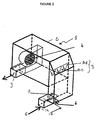
- the temperature-controlled air generator shown under the general reference 1, object of the invention, is more particularly intended to be used in the context livestock buildings or industrial buildings.
- This air generator can be placed indifferently to outside or inside the room to be heated.
- This generator 1 is constituted, in a manner known per se, a box 2, generally metallic, housing at least a gas burner 3 and at least one fan 4 of dilution.
- This dilution fan 4 arranged upstream or downstream of the burner 3, is intended to propel, by suction or blowing, the air circulating in said box in a room at a desired temperature.
- box 2 is equipped with a hot air outlet shown at 9 in the figures.
- the air generator conventionally comprises at least one air inlet.
- the flow of the dilution fan is chosen depending on the volume of the room to be heated to allow heating of the entire room volume.
- the generator 1 has at least two sources of air supply, one, shown in 5 in the figures, of recycled air drawn in the room to be heated, the other, shown in 6 aux figures, fresh air from outside the room.
- the fresh air inlet 6 thus consists of an opening formed in the bottom wall or in a side wall of the generator housing positioned outside the building, while the inlet 5 for recycled air is formed by a tube connected to a side wall of the generator of such so that the bottom wall of the tube is arranged coplanar at the bottom wall of the housing and that the end of the tube opens directly above the opening defining the entrance 6 fresh air.
- This generator 1 also includes a ventilation mixer 7 controllable to obtain an air flow in box 2 fresh air or a recirculated air stream or a mixture of fresh air and air recycled according to variations in conditions and / or occupants' ventilation needs from the local. So, thanks to such a generator, it is possible obtain 0 to 100% fresh air flow or 0 to 100% recirculated air flow or a mixture of fresh air and air recycled in any proportions determined by operator based on parameters chosen by this last, especially depending on weather conditions and / or the ventilation needs of the occupants of the premises.
- this mixer tap consists of a single movable flap 7 arranged at the confluence of the recycled air supply streams and in fresh air to regulate the flow of said sources 5, 6 air supply.
- the flap 7 is thus arranged at the intersection of inputs 5, 6 delimiting in the housing of the generator of the perpendicular opening planes between them.
- the plans for opening the inputs 5, 6 in the housing of the generator thus form a dihedral, the flap 7, of preferably housed inside the volume of the dihedral, being hingedly connected to the dihedral edge, this edge constituting the pivot axis of the flap 7.
- the pivot axis of flap 7 is horizontal.
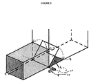
- This component 7 can be moved manually using a pull tab 10 allowing the flap to pivot around an axis 11 of rotation, as shown in Figure 3, or else be motorized by a servomotor controlled by a PLC.
- the arrangement of this component at the confluence of veins allows this component to be used as a obturation member unique for the two air intakes 5, 6 and to simplify its command on the move because naturally, when it closes a certain percentage entry, it opens the other entry in the same percentage at the same time.
- the temperature controlled air generator can both perform the functions of a heater and fan while maintaining energy consumption at a reasonable level consistent with that of a generator of air used exclusively as a heating device.
- the burner 3, housed in the box of the generator may be of the gas induction by air type.
- This type of burner makes it possible in particular to obtain a range of extended heating power setting.
- this heating power adjustment range includes values can vary from 1 to 10 while the burners classical atmospheres have a power of heaters can vary within a range of 1 to 3.
- these air induction type burners are safer because they don't require a power supply in pressurized gas.
- the gas is introduced into the air in function of the air flow, this air flow being obtained at by means of a fan supplied with primary air generally corresponding to outside air.
- combustion obtained by means of this type of burner is of better quality, in particular in terms of quantity of nitrogen and carbon oxides products.
- This type of burner can also be used with a combustion support, also called flame catcher, of the type consisting of a set of fibers metal formed from an iron-chromium-aluminum alloy supplemented with at least one rare earth such as yttrium.
- a combustion support also called flame catcher
- a combustion support of the type constituted by metallic fibers allows to increase so considerable range of power adjustment heated. This gives a heating power which can vary from 1 to 10 and not more than 1 to 3 as in the state of the technique. This results in a decrease in the frequency of switching between the on and off positions of the burner. This results for the user in an absence feeling of discomfort which was due to the inertia of conventional burners.
- each link is carried out according to a predetermined order depending on the relative positioning burners on the common gas supply line so as to allow automatic ignition of the flame of a BE slave burner by contact of the mixture air / gas expelled from said burner with the flame of a burner master BM or adjacent slave BE.
- the shutter with controlled opening / closing of the connection between a master or slave burner and the source gas supply can affect a lot of forms. It can thus be made up of a single organ common to all burners.
- this organ shutter is mounted in sliding sliding contact support inside the gas supply line and is axially movable inside said pipe for release and obstruct successively during its moving the connection port of a burner to the gas supply line.
- the displacement of this the shutter member can be operated manually or by means of a driving organ.
- This obturation member can by example consisting of a piston or a fitted drawer at least one external peripheral seal.
- the obturation member can also be made up of a pre-calibrated closure member, such as a valve loaded by an elastic return means, the opening or respectively the closing is a function of the pressure gas prevailing inside the supply line in gas.
- the tare weight of each sealing member is chosen depending on the relative positioning of the burner at which said organ relates.
- the loaded shutters by an elastic return means, such as a spring, are arranged respectively inside the pipe gas supply, between the gas supply source line gas and the burner to which they relate.
Landscapes
- Engineering & Computer Science (AREA)
- Chemical & Material Sciences (AREA)
- Combustion & Propulsion (AREA)
- Mechanical Engineering (AREA)
- General Engineering & Computer Science (AREA)
- Regulation And Control Of Combustion (AREA)
- Housing For Livestock And Birds (AREA)
- Ventilation (AREA)
Claims (6)
- Generator (1) für Luft mit gesteuerter Temperatur besonders für Aufzuchtställe oder Industriegebäude, wobei dieser Generator (1) aus einem Kasten (2) besteht, welcher mindestens einen Brenner (3) und mindestens einen Einblasventilator (4) aufweist, so dass die Luft, welche in dem genannten Kasten (2) zirkuliert, mit einer gewünschten Temperatur in einen Raum eingebracht wird, wobei dieser Generator mindestens zwei Quellen (5, 6) zur Beschickung mit Luft aufweist, wobei eine Quelle (5) für wiederaufbereitete Luft, welche aus dem Raum stammt, welcher zu beheizen ist, und die andere Quelle (6) für Frischluft vorgesehen ist, welche von außerhalb des Raumes stammt, wobei der Generator außerdem eine steuerbare Mischvorrichtung (7) für Luft und Gas aufweist, um in dem Kasten (2) einen Strom aus Frischluft oder einen Strom aus wiederaufbereiteter Luft oder aus einem Gemisch aus Frischluft und wiederaufbereiteter Luft je nach den Veränderungen der klimatischen Bedingungen und/oder des Ventilationsbedarfs der Bewohner des Raumes zu erhalten,
dadurch gekennzeichnet, dass diese Mischvorrichtung eine bewegliche Klappe (7) aufweist, welche an einer Stelle angeordnet ist, an der sich die Leitungen zur Versorgung mit wiederaufbereiteter Luft und mit Frischluft vereinen, so dass die Menge der genannten Quellen (5, 6) zur Versorgung mit Luft steuer- oder regelbar ist. - Generator (1) nach Anspruch 1,
dadurch gekennzeichnet, dass der Brenner (3) ein Brenner mit Gasinduktion durch die Luft ist, um einen erweiterten Regelungsbereich zu erhalten. - Generator (1) nach Anspruch 2,
dadurch gekennzeichnet, dass der Verbrennungsträger des Brenners eine Baugruppe von Metallfasern aufweist, die im wesentlichen aus einer Eisen-Chrom-Aluminiumlegierung bestehen. - Generator (1) nach einem der Ansprüche 1 bis 3,
dadurch gekennzeichnet, dass der Brenner mindestens zwei Brenner umfasst, die jeweils mit einer gemeinsamen Leitung zur Beschickung mit Gas verbunden sind, wobei einer der Brenner, der sogenannte Hauptbrenner (HB), mit einer Entzündungsvorrichtung für das Luft-/Gasgemisch und einer Vorrichtung zur Steuerung der Flamme ausgerüstet ist, während der andere Brenner oder die anderen Brenner, die sogenannten Nebenbrenner (NB), nicht über solche Vorrichtungen verfügen, wobei jeder einzelne Brenner mittels einer Verbindung unabhängig beschickt werden kann, welche durch das Öffnen/Verschließen absperrbar ist, das zwischen der Quelle zur Beschickung mit Gas und dem Brenner steuerbar ist, wobei das Öffnen/Verschließen jeder einzelnen Verbindung gemäß einer vorher bestimmten Abfolge je nach jeweiliger Anordnung der Brenner (NB, HB) an der gemeinsamen Leitung zur Beschickung mit Gas erfolgt, so dass die automatische Entzündung der Flamme eines Nebenbrenners (NB) durch den Kontakt des Luft-/Gasgemisches, welches von dem genannten Brenner ausgestoßen wird, mit der Flamme eines Hauptbrenners (HB) oder eines angrenzenden Nebenbrenners (NB) ermöglicht wird. - Generator (1) nach einem der Ansprüche 1 bis 4,
dadurch gekennzeichnet, dass er eine Vorrichtung zur Steuerung des Brenners (3) und der Mischvorrichtung (7; 8A, 8B) in Abhängigkeit von Parametern aufweist, welche mindestens die Außentemperatur, den Feuchtigkeitsgehalt im Inneren des Raumes und die Temperatur, welche in dem Raum herrscht, umfassen. - Generator (1) nach einem der Ansprüche 1 bis 5,
dadurch gekennzeichnet, dass die Quellen (5, 6) zur Einführung von Luft in den Generator Öffnungsebenen begrenzen, welche miteinander einen Dieder bilden, wobei die Klappe (7) gelenkig mit der Kante des Dieders verbunden ist, welche die Drehachse der Klappe (7) bildet.
Applications Claiming Priority (2)
| Application Number | Priority Date | Filing Date | Title |
|---|---|---|---|
| FR0004625A FR2807500B1 (fr) | 2000-04-11 | 2000-04-11 | Generateur d'air a temperature contolee notamment pour batiment d4elevage ou industriel |
| FR0004625 | 2000-04-11 |
Publications (3)
| Publication Number | Publication Date |
|---|---|
| EP1146292A1 EP1146292A1 (de) | 2001-10-17 |
| EP1146292A8 EP1146292A8 (de) | 2002-01-16 |
| EP1146292B1 true EP1146292B1 (de) | 2003-12-03 |
Family
ID=8849119
Family Applications (1)
| Application Number | Title | Priority Date | Filing Date |
|---|---|---|---|
| EP20010400824 Expired - Lifetime EP1146292B1 (de) | 2000-04-11 | 2001-03-30 | Temperaturgeregelte Lufterzeugungsvorrichtung inbesondere für Tierställe |
Country Status (4)
| Country | Link |
|---|---|
| EP (1) | EP1146292B1 (de) |
| DE (1) | DE60101343T2 (de) |
| ES (1) | ES2211745T3 (de) |
| FR (1) | FR2807500B1 (de) |
Families Citing this family (3)
| Publication number | Priority date | Publication date | Assignee | Title |
|---|---|---|---|---|
| FR2964448B1 (fr) * | 2010-09-07 | 2014-03-28 | 4E | Installation de ventilation, notamment de batiment d'elevage. |
| EP3769015B1 (de) * | 2018-03-23 | 2024-08-14 | Lead Leroy Concept | Belüftungsvorrichtung für tierzuchtgebäude, insbesondere für geflügel, mit einem wärmetauscher und luftheizmittel |
| FR3079108A1 (fr) * | 2018-03-23 | 2019-09-27 | Lead Leroy Concept | Dispositif de ventilation pour batiment d'elevage, notamment d'elevage avicole, comprenant un echangeur de chaleur et des moyens de chauffage de l'air |
Family Cites Families (4)
| Publication number | Priority date | Publication date | Assignee | Title |
|---|---|---|---|---|
| US4737103A (en) * | 1985-06-24 | 1988-04-12 | Siccardi Frank J | Fresh air monitoring and controls relating thereto |
| US5290188A (en) * | 1991-07-19 | 1994-03-01 | Professional Supply, Inc. | Inlet and damper system for airhouses |
| US5586932A (en) * | 1993-11-05 | 1996-12-24 | Professional Supply, Inc. | Environmental control airhouse with variable output |
| US5915960A (en) * | 1997-10-13 | 1999-06-29 | Greenheck Fan Corporation | Direct gas-fired heating and ventilation system with passive control damper |
-
2000
- 2000-04-11 FR FR0004625A patent/FR2807500B1/fr not_active Expired - Fee Related
-
2001
- 2001-03-30 EP EP20010400824 patent/EP1146292B1/de not_active Expired - Lifetime
- 2001-03-30 DE DE2001601343 patent/DE60101343T2/de not_active Expired - Lifetime
- 2001-03-30 ES ES01400824T patent/ES2211745T3/es not_active Expired - Lifetime
Also Published As
| Publication number | Publication date |
|---|---|
| EP1146292A1 (de) | 2001-10-17 |
| FR2807500A1 (fr) | 2001-10-12 |
| EP1146292A8 (de) | 2002-01-16 |
| FR2807500B1 (fr) | 2002-12-13 |
| DE60101343T2 (de) | 2004-12-02 |
| ES2211745T3 (es) | 2004-07-16 |
| DE60101343D1 (de) | 2004-01-15 |
Similar Documents
| Publication | Publication Date | Title |
|---|---|---|
| CA2330810C (fr) | Procede et dispositif de climatisation | |
| US9441839B2 (en) | Heating apparatus with fan | |
| CA2532002C (en) | Fragrance dispersers | |
| US10677495B2 (en) | Stove | |
| US9441840B2 (en) | Heating apparatus with fan | |
| US6257230B1 (en) | Adapter for ventless fireplace | |
| EP1563228B1 (de) | Heizung mit hohem wirkungsgrad | |
| EP1146292B1 (de) | Temperaturgeregelte Lufterzeugungsvorrichtung inbesondere für Tierställe | |
| EP2246625B1 (de) | Vorrichtung zur Steuerung der Ofenluftzufuhr, Ofen mit einer solchen Vorrichtung und ein Verfahren zur Nutzung der Vorrichtung. | |
| FR2964448A1 (fr) | Installation de ventilation, notamment de batiment d'elevage. | |
| FR3053103B1 (fr) | Boite a melange de flux d'air, element pour la realisation d'une telle boite et installation de ventilation mecanique integrant une telle boite a melange | |
| FR2556820A1 (fr) | Cheminee de chauffage avec production d'air chaud | |
| EP0246948A1 (de) | Heiz- und Belüftungseinrichtung für ein Kraftfahrzeug | |
| FR2750479A1 (fr) | Unite destinee a la recirculation d'air frais | |
| CA3097261A1 (en) | Solid fuel burning appliance and method to control same | |
| FR2762897A1 (fr) | Foyer ferme de cheminee perfectionne | |
| CA1258018A (fr) | Recuperateur de calories a foyer ouvert pour cheminees d'appartement ou de maison individuelle | |
| EP4323695B1 (de) | Holzheizvorrichtung | |
| FR2544467A1 (fr) | Support de foyer de cheminee | |
| FR2955919A1 (fr) | Dispositif de repartition d'un debit d'air, installation de ventilation et procede de regulation d'une telle installation | |
| NL2010245C2 (en) | Convertible gas fireplace and method for converting such fireplace. | |
| FR2941036A1 (fr) | Poele domestique muni d'un mecanisme d'acheminement selectif d'air secondaire vers un conduit d'evacuation des fumees ou vers une chambre de combustion | |
| FR2556079A1 (fr) | Poele generateur d'air chaud realisable a l'aide de modules de fonte moulee sans noyautage | |
| EP0165175A2 (de) | Abzug und Lüftungsanlage, regelbar in Abhängigkeit von der Temperatur und dem Feuchtigkeitsgrad des Luftstroms | |
| IT202400003871A1 (it) | Stufa ad alimentazione ibrida a legna e pellet e metodo per alimentare detta stufa |
Legal Events
| Date | Code | Title | Description |
|---|---|---|---|
| PUAI | Public reference made under article 153(3) epc to a published international application that has entered the european phase |
Free format text: ORIGINAL CODE: 0009012 |
|
| AK | Designated contracting states |
Kind code of ref document: A1 Designated state(s): DE ES FR GB IT Kind code of ref document: A1 Designated state(s): AT BE CH CY DE DK ES FI FR GB GR IE IT LI LU MC NL PT SE TR |
|
| AX | Request for extension of the european patent |
Free format text: AL;LT;LV;MK;RO;SI |
|
| RAP1 | Party data changed (applicant data changed or rights of an application transferred) |
Owner name: 4E |
|
| 17P | Request for examination filed |
Effective date: 20020306 |
|
| AKX | Designation fees paid |
Free format text: DE ES FR GB IT |
|
| GRAH | Despatch of communication of intention to grant a patent |
Free format text: ORIGINAL CODE: EPIDOS IGRA |
|
| GRAS | Grant fee paid |
Free format text: ORIGINAL CODE: EPIDOSNIGR3 |
|
| GRAA | (expected) grant |
Free format text: ORIGINAL CODE: 0009210 |
|
| AK | Designated contracting states |
Kind code of ref document: B1 Designated state(s): DE ES FR GB IT |
|
| PG25 | Lapsed in a contracting state [announced via postgrant information from national office to epo] |
Ref country code: IT Free format text: LAPSE BECAUSE OF FAILURE TO SUBMIT A TRANSLATION OF THE DESCRIPTION OR TO PAY THE FEE WITHIN THE PRESCRIBED TIME-LIMIT;WARNING: LAPSES OF ITALIAN PATENTS WITH EFFECTIVE DATE BEFORE 2007 MAY HAVE OCCURRED AT ANY TIME BEFORE 2007. THE CORRECT EFFECTIVE DATE MAY BE DIFFERENT FROM THE ONE RECORDED. Effective date: 20031203 Ref country code: GB Free format text: LAPSE BECAUSE OF FAILURE TO SUBMIT A TRANSLATION OF THE DESCRIPTION OR TO PAY THE FEE WITHIN THE PRESCRIBED TIME-LIMIT Effective date: 20031203 |
|
| REG | Reference to a national code |
Ref country code: GB Ref legal event code: FG4D Free format text: NOT ENGLISH |
|
| REF | Corresponds to: |
Ref document number: 60101343 Country of ref document: DE Date of ref document: 20040115 Kind code of ref document: P |
|
| GBV | Gb: ep patent (uk) treated as always having been void in accordance with gb section 77(7)/1977 [no translation filed] |
Effective date: 20031203 |
|
| REG | Reference to a national code |
Ref country code: ES Ref legal event code: FG2A Ref document number: 2211745 Country of ref document: ES Kind code of ref document: T3 |
|
| PLBE | No opposition filed within time limit |
Free format text: ORIGINAL CODE: 0009261 |
|
| STAA | Information on the status of an ep patent application or granted ep patent |
Free format text: STATUS: NO OPPOSITION FILED WITHIN TIME LIMIT |
|
| 26N | No opposition filed |
Effective date: 20040906 |
|
| REG | Reference to a national code |
Ref country code: FR Ref legal event code: CD Owner name: SYSTEL, FR Effective date: 20121108 |
|
| PGFP | Annual fee paid to national office [announced via postgrant information from national office to epo] |
Ref country code: ES Payment date: 20130314 Year of fee payment: 13 Ref country code: DE Payment date: 20130321 Year of fee payment: 13 |
|
| REG | Reference to a national code |
Ref country code: FR Ref legal event code: CA Effective date: 20131031 |
|
| PGFP | Annual fee paid to national office [announced via postgrant information from national office to epo] |
Ref country code: FR Payment date: 20140319 Year of fee payment: 14 |
|
| REG | Reference to a national code |
Ref country code: DE Ref legal event code: R119 Ref document number: 60101343 Country of ref document: DE |
|
| REG | Reference to a national code |
Ref country code: DE Ref legal event code: R119 Ref document number: 60101343 Country of ref document: DE Effective date: 20141001 |
|
| PG25 | Lapsed in a contracting state [announced via postgrant information from national office to epo] |
Ref country code: DE Free format text: LAPSE BECAUSE OF NON-PAYMENT OF DUE FEES Effective date: 20141001 |
|
| REG | Reference to a national code |
Ref country code: ES Ref legal event code: FD2A Effective date: 20150731 |
|
| PG25 | Lapsed in a contracting state [announced via postgrant information from national office to epo] |
Ref country code: ES Free format text: LAPSE BECAUSE OF NON-PAYMENT OF DUE FEES Effective date: 20140331 |
|
| REG | Reference to a national code |
Ref country code: FR Ref legal event code: ST Effective date: 20151130 |
|
| PG25 | Lapsed in a contracting state [announced via postgrant information from national office to epo] |
Ref country code: FR Free format text: LAPSE BECAUSE OF NON-PAYMENT OF DUE FEES Effective date: 20150331 |