EP1146249B1 - Dämpfungssystem für waltzen von wellpappenmaschinen - Google Patents
Dämpfungssystem für waltzen von wellpappenmaschinen Download PDFInfo
- Publication number
- EP1146249B1 EP1146249B1 EP99953998A EP99953998A EP1146249B1 EP 1146249 B1 EP1146249 B1 EP 1146249B1 EP 99953998 A EP99953998 A EP 99953998A EP 99953998 A EP99953998 A EP 99953998A EP 1146249 B1 EP1146249 B1 EP 1146249B1
- Authority
- EP
- European Patent Office
- Prior art keywords
- roller
- damping
- damping device
- rollers
- jackets
- Prior art date
- Legal status (The legal status is an assumption and is not a legal conclusion. Google has not performed a legal analysis and makes no representation as to the accuracy of the status listed.)
- Expired - Lifetime
Links
- 238000013016 damping Methods 0.000 title claims abstract description 54
- 238000004519 manufacturing process Methods 0.000 title claims abstract description 12
- 239000004519 grease Substances 0.000 claims description 5
- 230000008859 change Effects 0.000 claims description 3
- 230000000694 effects Effects 0.000 claims description 3
- 238000010348 incorporation Methods 0.000 abstract description 4
- 239000000123 paper Substances 0.000 description 10
- 238000010438 heat treatment Methods 0.000 description 6
- 238000004026 adhesive bonding Methods 0.000 description 5
- 238000013461 design Methods 0.000 description 3
- 238000009434 installation Methods 0.000 description 3
- 230000009471 action Effects 0.000 description 2
- 230000007797 corrosion Effects 0.000 description 2
- 238000005260 corrosion Methods 0.000 description 2
- 238000005520 cutting process Methods 0.000 description 2
- 230000010339 dilation Effects 0.000 description 2
- 229920006395 saturated elastomer Polymers 0.000 description 2
- 238000012546 transfer Methods 0.000 description 2
- 229910001369 Brass Inorganic materials 0.000 description 1
- 230000004913 activation Effects 0.000 description 1
- 230000004075 alteration Effects 0.000 description 1
- 230000015572 biosynthetic process Effects 0.000 description 1
- 239000010951 brass Substances 0.000 description 1
- 230000007547 defect Effects 0.000 description 1
- 238000012423 maintenance Methods 0.000 description 1
- 239000000463 material Substances 0.000 description 1
- 238000000034 method Methods 0.000 description 1
- 230000008569 process Effects 0.000 description 1
Images


Classifications
-
- B—PERFORMING OPERATIONS; TRANSPORTING
- B31—MAKING ARTICLES OF PAPER, CARDBOARD OR MATERIAL WORKED IN A MANNER ANALOGOUS TO PAPER; WORKING PAPER, CARDBOARD OR MATERIAL WORKED IN A MANNER ANALOGOUS TO PAPER
- B31F—MECHANICAL WORKING OR DEFORMATION OF PAPER, CARDBOARD OR MATERIAL WORKED IN A MANNER ANALOGOUS TO PAPER
- B31F1/00—Mechanical deformation without removing material, e.g. in combination with laminating
- B31F1/20—Corrugating; Corrugating combined with laminating to other layers
- B31F1/24—Making webs in which the channel of each corrugation is transverse to the web feed
- B31F1/26—Making webs in which the channel of each corrugation is transverse to the web feed by interengaging toothed cylinders cylinder constructions
- B31F1/28—Making webs in which the channel of each corrugation is transverse to the web feed by interengaging toothed cylinders cylinder constructions combined with uniting the corrugated webs to flat webs ; Making double-faced corrugated cardboard
- B31F1/2845—Details, e.g. provisions for drying, moistening, pressing
- B31F1/2863—Corrugating cylinders; Supporting or positioning means therefor; Drives therefor
-
- F—MECHANICAL ENGINEERING; LIGHTING; HEATING; WEAPONS; BLASTING
- F16—ENGINEERING ELEMENTS AND UNITS; GENERAL MEASURES FOR PRODUCING AND MAINTAINING EFFECTIVE FUNCTIONING OF MACHINES OR INSTALLATIONS; THERMAL INSULATION IN GENERAL
- F16C—SHAFTS; FLEXIBLE SHAFTS; ELEMENTS OR CRANKSHAFT MECHANISMS; ROTARY BODIES OTHER THAN GEARING ELEMENTS; BEARINGS
- F16C13/00—Rolls, drums, discs, or the like; Bearings or mountings therefor
-
- F—MECHANICAL ENGINEERING; LIGHTING; HEATING; WEAPONS; BLASTING
- F16—ENGINEERING ELEMENTS AND UNITS; GENERAL MEASURES FOR PRODUCING AND MAINTAINING EFFECTIVE FUNCTIONING OF MACHINES OR INSTALLATIONS; THERMAL INSULATION IN GENERAL
- F16F—SPRINGS; SHOCK-ABSORBERS; MEANS FOR DAMPING VIBRATION
- F16F15/00—Suppression of vibrations in systems; Means or arrangements for avoiding or reducing out-of-balance forces, e.g. due to motion
- F16F15/10—Suppression of vibrations in rotating systems by making use of members moving with the system
- F16F15/14—Suppression of vibrations in rotating systems by making use of members moving with the system using masses freely rotating with the system, i.e. uninvolved in transmitting driveline torque, e.g. rotative dynamic dampers
-
- B—PERFORMING OPERATIONS; TRANSPORTING
- B65—CONVEYING; PACKING; STORING; HANDLING THIN OR FILAMENTARY MATERIAL
- B65H—HANDLING THIN OR FILAMENTARY MATERIAL, e.g. SHEETS, WEBS, CABLES
- B65H2601/00—Problem to be solved or advantage achieved
- B65H2601/50—Diminishing, minimizing or reducing
- B65H2601/52—Diminishing, minimizing or reducing entities relating to handling machine
- B65H2601/524—Vibration
Definitions
- corrugated cardboard two corrugated rollers are used, in charge of making the corrugated conformation of the intermediate paper or core of the cardboard, and a flat roller, in charge of fixing another paper, which determines one of the flat faces of the cardboard, on the corrugated one.
- the paper building up the other flat face of the cardboard is glued on later in another part of the installation.
- the only variable to change the vibration frequency is the rotation speed of the rollers, but this is defined by the type and quantity of orders, so that actuating on this variable is very restricted, or even null.
- the vibration frequency which in principle can be any and therefore can coincide with some of the resonance frequencies (or natural frequencies) of some part of the corrugating device, as for example the rollers; so that when the corrugating device is especially problematic, low weight sheets are used, i.e. they provide little damping, the notch pitch profile is high and at great height, if moreover the resonance frequencies of the rollers are reached, the possibilities of the cardboard to be faulty are very high at certain speeds.
- Another purpose to solve the problem is by trying to move away the first natural frequency from the frequency ranges of the operation vibration, but nevertheless the geometric and material limitations of the roller design make that the frequency deviation possibility is not enough, always having it inside the working ranges.
- the first natural frequency of the rollers is the only one that is reached in the corrugating devices, since when the vibration frequency is double the first frequency, it also excites the roller to the first natural frequency.
- the first vibration mode represents the form that the roller acquires when this gets excited at the first natural frequency, being this form similar to that of roller deformation, when it flexes by a load applied in the centre, i.e. that the deformation is maximum in the centre and it falls progressively towards the ends. From this it can be seen that the problems of an excess mark and cardboard cutting in the first natural frequency appears in the central area of the rollers with tendency to disappear towards the end.
- EP 0 044 612 A discloses a damping system for corrugated cardboard fabrication rollers according to the preamble of claim 1 and comprising upper and lower corrugated rollers and a pressure roller. Vibration reducing means is provided in a hollow interior of at least one of the rollers.
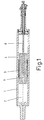
- a damping system for corrugated cardboard fabrication rollers comprising: a roller with a hollow body; and a damping device located inside a chamber of the roller for counteracting vibrations of the roller, the damping device being mounted to substantially prevent movement of the damping device in relation to a wall of the roller; characterised in that the damping device comprises: two coaxial jackets defining a space therebetween; two rings each of which closes an opposite end of the space between the jackets; a plurality of damping bushings as well as the two rings loosely situated in the space between the jackets, with grease filling a gap between adjacent bushings; and a tubular shaft passing through the innermost of the jackets, the shaft supporting a nut and a friction mass at each end of the jackets, each nut being adjustable to press an elastic washer which in turn presses the respective friction mass thereby tightening the nut regulates a damping effect of the damping device.
- This system object of the invention consists in including inside the rollers a damping device in solidary assembly respect to the wall of the corresponding roller, so that when vibrations take place inside the roller, the interior device also vibrates, being opposed its vibration to that from the activation source, which is the roller, so that the vibrations of this are damped, disappearing the negative causes of the same of the paper to produce the corrugated cardboard.
- the damping effect takes place especially at critical speeds, which is when the roller resonance is reached; being foreseen a realisation of the device that acts particular at these speeds, while another realisation damps the vibrations at all the critical speeds, optimizing the damping at these speeds.
- the assembly of the device respect to the roller wall is established by means of a flexible jacket and with interference adjustment, so that the dilation differences because of the temperature are absorbed, without affecting the roller outside.
- the adjustment areas between the damping device and the roller wall are moreover established with holes which allow the vapour and condensate passage from one side to the other, while centrally through the damping device itself a conduit is defined which allows the vapour passage from the entrance tube, with which the roller heating does not suffer damage because of the damping device incorporation.
- the preconized system provides an advantageous practical solution against the vibration problem of the mentioned rollers to produce corrugated cardboard, fulfilling with the following particularities:
- the object of the invention refers to a damping system to compensate the vibrations of the rollers to produce corrugated cardboard, with the purpose of eliminating the defects that the mentioned vibrations cause in the produced cardboard.
- the system consists in including inside the hollow body (1) of the rollers a device that vibrates activated by the vibration that the roller (1) acquires during the operation, so that the mentioned vibration of the incorporated device is opposed to the vibration characteristic of the roller (1), being therefore damped.
- the damping device is included in the vapour chamber (2) defined by the rollers (1) inside for the introduction of the heating vapour; being formed the mentioned damping device, according to an arrangement (figures 1 to 3) by a device whose first natural frequency coincides with the first natural frequency of the roller (1) with the mentioned device mounted so that when the first natural frequency of the roller (1) is reached, this enters in resonance, the same as the damping device, reacting this against its excitement source, which is the roller (1) itself.
- the device is formed according to the arrangement by a jacket (3) and a core (4), which are mounted with interference adjustment between them, by means of contact supports (5) which establish a solidary union between the mentioned parts (3) and (4).
- the device set is mounted in turn with interference adjustment on the roller body interior (1) by means of respective contact supports (6), remaining this way the mentioned device fixedly fastened in connection with the indicated body (1) of the corresponding roller.
- the supports (6) between the jacket (3) of the damping device and the body (1) of the roller toothings are foreseen with which the vapour and the condensate can pass through the holes left by the teeth, without harming the heating.
- the temperature that the damping device acquires is logically bigger than that of the roller (1), so that the expansions of the first will be bigger than those of the second, which can give rise to deformations at the roller (1) outer part, affecting the production, getting faulty corrugated cardboard.
- the supports (5) between the jacket (3) and the core (4) of the damping device and the supports (6) between the mentioned jacket (3) and the roller body (1) are foreseen unfaced, so that the flexibility of the jacket (3) absorbs the expansion differences without these being transmitted to the roller body (1).
- the core geometry (4) and its assembly supports (6) are such that the first natural frequency to flexion of the same coincides with that of the roller (1) provided with the damping device, so that the resonance of the mentioned core (4) also enters in the roller (1) resonance, being opposed its vibration to that of the roller (1) by the principle of action and reaction.
- the core (4) moreover defines an axial hole (7), through which the vapour passage from the corresponding entrance tube (8) is possible till the other side of the vapour chamber (2); so that the vapour, together with the condensate that is formed, pass to the front side of the chamber (2) through the holes between the support teeth (6) between the jacket (3) and the roller body (1).
- the damping device is formed by a device that acts at all the speeds, included the critical one, absorbing the vibration energy, although the action is more intense at critical speeds so that the application will be directed to optimizing the damping at those speeds.
- the device includes a jacket (9), at the ends of which some rings (10) are mounted at the inside with interference adjustment, regarding which another jacket (11) is in turn incorporated, at the inside, also with interference adjustment.
- damping bushings are included (12), which are established with an intermediate play that is stuffed with grease, by means of which the surfaces are protected against corrosion, at the same time that their viscosity favours the damping of the sliding friction between the bushings (12).
- the mentioned play between the bushings (12) can selectively be varied, to get an optimum damping at the critical speed of each case.
- a tubular shaft (13) which crosses axially the set is installed, on which some nuts are mounted (14) which press the respective elastic washers (15), which in turn press some corresponding friction masses (16) that friction against the installed set of damping bushings (12).
- the pressure of the elastic washers (15) is also adjustable to obtain a maximum damping in each case; allowing the tubular shaft (13) the vapour passage from the respective entrance tube (8); while the fixing of the set respect to the corresponding roller body (1) is established in this case with interference adjustment, by means of contact supports (17) between the jacket (9) and the roller body (1) in such a way that the expansion differences because of the temperature are absorbed by the elasticity of the jacket (9) itself without affecting the roller body (1).
- the supports (17) are in this case also established toothed, allowing this way the condensate and vapour passage between both parts of the respective vapour chamber (2) separated by the incorporation of the device.
- the friction surfaces of the friction masses (16) are charged again in the production with a brass lining, to avoid the seizing and to assure an appropriate duration of the mentioned surfaces; while the holes between the nuts (14), the friction masses (16), the shaft (13) and the inner jacket (11), are also stuffed with grease to protect the contact surfaces, including between the nuts (14) and the friction masses (16) an O-ring (18), between the friction masses (16) and the interior jacket (11) another O-ring (19),and between the nuts (14) and the shaft (13) another O-ring (20), by means of which appropriate closures are established which avoid the escape of the grease out of the mentioned holes.
Landscapes
- Engineering & Computer Science (AREA)
- General Engineering & Computer Science (AREA)
- Mechanical Engineering (AREA)
- Physics & Mathematics (AREA)
- Acoustics & Sound (AREA)
- Aviation & Aerospace Engineering (AREA)
- Machines For Manufacturing Corrugated Board In Mechanical Paper-Making Processes (AREA)
- Container Filling Or Packaging Operations (AREA)
- Laminated Bodies (AREA)
Claims (3)
- Dämpfungssystem für Wellpappe-Fertigungswalzen, welches umfasst:dadurch gekennzeichnet, dass die Dämpfungsvorrichtung umfasst:eine Walze (1) mit einem hohlen Körper; undeine Dämpfungsvorrichtung, positioniert innerhalb einer Kammer (2) der Walze (1), um Vibrationen der Walze entgegenzuwirken, wobei die Dämpfungsvorrichtung so angebracht ist, dass sie im Wesentlichen die Bewegung der Dämpfungsvorrichtung in Bezug auf eine Wand der Walze verhindert;zwei koaxiale Ummantelungen (9, 11), welche einen Raum zwischen denselben begrenzen;zwei Ringe (10), wobei jeder von ihnen ein entgegengesetztes Ende des Raums zwischen den Ummantelungen schließt;eine Vielzahl von Dämpfungsbuchsen (12) sowie die zwei Ringe (10), lose positioniert im Raum zwischen den Ummantelungen, wobei Fett eine Lükke zwischen aneinander angrenzenden Buchsen ausfüllt; undeine röhrenförmige Welle (13), welche durch das Innerste der Ummantelungen hindurch geht, wobei die Welle eine Mutter (14) und eine Reibungsmasse (16) an jedem Ende der Ummantelungen trägt und jede Mutter so einstellbar ist, dass sie Druck auf eine elastische Dichtungsscheibe (15) ausübt, welche wiederum Druck auf die entsprechende Reibungsmasse ausübt, wodurch das Anziehen der Mutter einen Dämpfungseffekt der Dämpfungsvorrichtung regelt.
- Dämpfungssystem nach Anspruch 1, dadurch gekennzeichnet, dass die Dämpfungsvorrichtung mit Hilfe von Stützkontakten (17) auf der Walze (1) mit Interferenzeinstellung montiert ist und die äußerste Ummantelung elastisch ist und die Elastizität der äußersten Ummantelung (9) so wirkt, dass sie einen Unterschied in der Ausdehnung der Dämpfungsvorrichtung und des Walzenkörpers (1) ausgleicht, die durch eine Änderung der Temperatur hervorgerufen wird, wodurch die Wahrscheinlichkeit verringert wird, dass der Unterschied bei der Ausdehnung die Walze (1) deformiert.
- Dämpfungssystem nach Anspruch 1 oder Anspruch 2, dadurch gekennzeichnet, dass die Dämpfungsvorrichtung in der Walze 1 mit Hilfe von Stützkontakten (17) montiert ist und die Stützkontakte (17) Zähne aufweisen, welche Hohlräume für den Durchgang von Kondensat und Dampf von einer Seite der Walzenkammer (2) zur anderen Seite bilden.
Applications Claiming Priority (3)
| Application Number | Priority Date | Filing Date | Title |
|---|---|---|---|
| ES9802450 | 1998-11-23 | ||
| ES009802450A ES2144975B1 (es) | 1998-11-23 | 1998-11-23 | Sistema de amortiguacion para rodillos de fabricacion de carton ondulado. |
| PCT/ES1999/000357 WO2000031437A1 (es) | 1998-11-23 | 1999-11-08 | Sistema de amortiguacion para rodillos de fabricacion de carton ondulado |
Publications (2)
| Publication Number | Publication Date |
|---|---|
| EP1146249A1 EP1146249A1 (de) | 2001-10-17 |
| EP1146249B1 true EP1146249B1 (de) | 2003-05-21 |
Family
ID=8305878
Family Applications (1)
| Application Number | Title | Priority Date | Filing Date |
|---|---|---|---|
| EP99953998A Expired - Lifetime EP1146249B1 (de) | 1998-11-23 | 1999-11-08 | Dämpfungssystem für waltzen von wellpappenmaschinen |
Country Status (7)
| Country | Link |
|---|---|
| US (1) | US6471625B1 (de) |
| EP (1) | EP1146249B1 (de) |
| AT (1) | ATE241098T1 (de) |
| AU (1) | AU1047500A (de) |
| DE (1) | DE69908183T2 (de) |
| ES (1) | ES2144975B1 (de) |
| WO (1) | WO2000031437A1 (de) |
Cited By (1)
| Publication number | Priority date | Publication date | Assignee | Title |
|---|---|---|---|---|
| CN102182789A (zh) * | 2011-04-27 | 2011-09-14 | 东华大学 | 一种用于悬臂式空心薄壁转子的调谐质量减振器 |
Families Citing this family (8)
| Publication number | Priority date | Publication date | Assignee | Title |
|---|---|---|---|---|
| US7067027B2 (en) | 2001-11-30 | 2006-06-27 | Xerox Corporation | Method of making an electro-mechanical roll |
| US6584296B1 (en) * | 2001-11-30 | 2003-06-24 | Xerox Corporation | Electro-mechanical roll with core and segments |
| JP4333581B2 (ja) * | 2002-07-31 | 2009-09-16 | 日本ゼオン株式会社 | 熱可塑性エラストマー成形体 |
| DE10248519B4 (de) * | 2002-10-17 | 2006-11-02 | Voith Patent Gmbh | Mittelwalze eines Kalanders und Kalander |
| US20080000363A1 (en) * | 2006-06-29 | 2008-01-03 | Metso Paper, Inc. | Adjustable Anti-Barring Device for Calender Rolls |
| DE102014119043B4 (de) * | 2014-12-18 | 2017-07-13 | Axmann Investment Gmbh | Gurtbandförderer |
| CN110744866A (zh) * | 2019-05-09 | 2020-02-04 | 抚顺东旭精工制辊科技有限公司 | 一种薄壁结构辊子 |
| CN111016298A (zh) * | 2019-12-24 | 2020-04-17 | 广州市新达丰纸品有限公司 | 一种瓦楞辊 |
Family Cites Families (20)
| Publication number | Priority date | Publication date | Assignee | Title |
|---|---|---|---|---|
| US905111A (en) * | 1907-12-23 | 1908-11-24 | Joseph J Stehling | Flexible roll for leather-splitting machines. |
| US1271194A (en) * | 1917-11-26 | 1918-07-02 | Peter Meyer | Spring-roll. |
| US1883183A (en) * | 1930-07-28 | 1932-10-18 | Herman G Weber | Marking roll composition |
| US1883185A (en) * | 1930-07-28 | 1932-10-18 | Herman G Weber | Marking roll |
| US2114378A (en) * | 1936-11-30 | 1938-04-19 | Oxford Varnish Corp | Printing roll |
| US2803126A (en) * | 1956-05-16 | 1957-08-20 | Joseph A Meyer | Ring roll in leather-splitting machines |
| US3094771A (en) * | 1961-06-13 | 1963-06-25 | Mount Hope Machinery Ltd | Table roll with means for removing longitudinal curvature |
| US3075406A (en) * | 1961-07-13 | 1963-01-29 | Gen Motors Corp | Propeller shaft damper |
| US3389450A (en) * | 1966-05-20 | 1968-06-25 | Mount Hope Machine Company Inc | Non-deflecting roll |
| US3604087A (en) * | 1970-03-13 | 1971-09-14 | Beloit Corp | Antideflection roll |
| US3653108A (en) * | 1970-06-12 | 1972-04-04 | Sommer & Maca Glass Machinery | Roller assembly |
| US3848304A (en) * | 1973-02-07 | 1974-11-19 | Beloit Corp | Variable curvature beam |
| DE3011385A1 (de) * | 1980-03-25 | 1981-10-01 | Hauni-Werke Körber & Co KG, 2050 Hamburg | Tragwalzen-rollvorrichtung fuer endlose materialbahnen |
| EP0044612B1 (de) * | 1980-06-27 | 1984-12-12 | Mitsubishi Jukogyo Kabushiki Kaisha | Einseitige Wellpappenmaschine |
| US4604778A (en) * | 1985-09-20 | 1986-08-12 | Edwards William H | Filled calender roll and method of building same |
| DE3632418A1 (de) * | 1986-09-24 | 1988-03-31 | Bayerische Motoren Werke Ag | Anordnung zur schwingungsdaempfung eines hohlfoermigen bauteils |
| DE4033278C1 (de) * | 1990-10-19 | 1992-03-12 | Heidelberger Druckmaschinen Ag, 6900 Heidelberg, De | |
| KR940011648A (ko) * | 1992-11-17 | 1994-06-21 | 존 디. 왈턴 | 전기강의 자기영역 구조 정련을 위한 부채꼴 앤빌 로울러 |
| FR2723625B1 (fr) * | 1994-08-09 | 1996-11-08 | Heidelberg Harris Sa | Procede et dispositif d'amortissement des vibrations en flexion des cylindres dans une presse a imprimer. |
| DK0738674T3 (da) * | 1995-04-03 | 2000-05-15 | Baeltix Maskinfabrikken As | Modulsæt til opbygning af en drivtromle til en båndtransportør |
-
1998
- 1998-11-23 ES ES009802450A patent/ES2144975B1/es not_active Expired - Fee Related
-
1999
- 1999-11-08 DE DE69908183T patent/DE69908183T2/de not_active Expired - Lifetime
- 1999-11-08 US US09/856,057 patent/US6471625B1/en not_active Expired - Fee Related
- 1999-11-08 AT AT99953998T patent/ATE241098T1/de not_active IP Right Cessation
- 1999-11-08 AU AU10475/00A patent/AU1047500A/en not_active Abandoned
- 1999-11-08 EP EP99953998A patent/EP1146249B1/de not_active Expired - Lifetime
- 1999-11-08 WO PCT/ES1999/000357 patent/WO2000031437A1/es not_active Ceased
Cited By (2)
| Publication number | Priority date | Publication date | Assignee | Title |
|---|---|---|---|---|
| CN102182789A (zh) * | 2011-04-27 | 2011-09-14 | 东华大学 | 一种用于悬臂式空心薄壁转子的调谐质量减振器 |
| CN102182789B (zh) * | 2011-04-27 | 2012-11-07 | 东华大学 | 一种用于悬臂式空心薄壁转子的调谐质量减振器 |
Also Published As
| Publication number | Publication date |
|---|---|
| DE69908183D1 (de) | 2003-06-26 |
| EP1146249A1 (de) | 2001-10-17 |
| US6471625B1 (en) | 2002-10-29 |
| WO2000031437A1 (es) | 2000-06-02 |
| AU1047500A (en) | 2000-06-13 |
| DE69908183T2 (de) | 2004-04-01 |
| ES2144975A1 (es) | 2000-06-16 |
| ES2144975B1 (es) | 2000-12-01 |
| ATE241098T1 (de) | 2003-06-15 |
Similar Documents
| Publication | Publication Date | Title |
|---|---|---|
| US6471625B1 (en) | Damping system for corrugated cardboard fabrication rollers | |
| CA1292494C (en) | Bearing support | |
| FI70988B (fi) | Pressvals med reglerbar nedboejning | |
| JPH11510777A (ja) | 巻取り方法および装置 | |
| US20050076675A1 (en) | Method and device for producing a cylindrical glass body | |
| JPS62199892A (ja) | 静止サイホン用ロータリジョイント | |
| EP2032872B1 (de) | Anordnung zum dämpfen von schwingungen in einer schwingungsmasse in einer papier-/kartonmaschinenumgebung | |
| US20020183180A1 (en) | Roll | |
| KR0174146B1 (ko) | 칼렌더 롤러 | |
| US4542566A (en) | Corrugating roller | |
| FI118858B (fi) | Järjestelmä paperikoneen osan värähtelyiden vaimentamiseksi ja estämiseksi | |
| EP1588064B1 (de) | Rohrrolle für eine papiermaschine und verfahren zur herstellungeiner rohrrolle | |
| CA2635512C (en) | Support arrangement of roll in fibrous-web machine | |
| WO2000078534A1 (en) | Single facer with resilient small diameter corrugating roll | |
| EP0044612B1 (de) | Einseitige Wellpappenmaschine | |
| US20080058188A1 (en) | Roll | |
| EP1226025B1 (de) | Schwingungsdämpfende riffelwalze | |
| EA000188B1 (ru) | Каландр | |
| EP2398961A1 (de) | Anordnung zur vibrationsdämpfung in einer faservliesmaschine | |
| GB2121511A (en) | Drying cylinder adapted to be heated with steam | |
| FI110333B (fi) | Sovitelma monitelakalanterin värähtelyjen vaimentamiseksi | |
| US3521340A (en) | Fluid bearing roll with vibration damping means | |
| JP4452409B2 (ja) | 加熱可能なカレンダーロール | |
| US6521090B1 (en) | Method and device for changing the natural frequency of a nip roll construction in a paper or board machine | |
| CN211012392U (zh) | 一种三筒烘干机滚筒固定装置 |
Legal Events
| Date | Code | Title | Description |
|---|---|---|---|
| PUAI | Public reference made under article 153(3) epc to a published international application that has entered the european phase |
Free format text: ORIGINAL CODE: 0009012 |
|
| 17P | Request for examination filed |
Effective date: 20010611 |
|
| AK | Designated contracting states |
Kind code of ref document: A1 Designated state(s): AT BE CH CY DE DK ES FI FR GB GR IE IT LI LU MC NL PT SE |
|
| AX | Request for extension of the european patent |
Free format text: AL;LT PAYMENT 20010611;LV;MK;RO;SI |
|
| 17Q | First examination report despatched |
Effective date: 20020214 |
|
| GRAH | Despatch of communication of intention to grant a patent |
Free format text: ORIGINAL CODE: EPIDOS IGRA |
|
| GRAH | Despatch of communication of intention to grant a patent |
Free format text: ORIGINAL CODE: EPIDOS IGRA |
|
| GRAA | (expected) grant |
Free format text: ORIGINAL CODE: 0009210 |
|
| AK | Designated contracting states |
Designated state(s): AT BE CH CY DE DK ES FI FR GB GR IE IT LI LU MC NL PT SE |
|
| AX | Request for extension of the european patent |
Extension state: LT |
|
| PG25 | Lapsed in a contracting state [announced via postgrant information from national office to epo] |
Ref country code: NL Free format text: LAPSE BECAUSE OF FAILURE TO SUBMIT A TRANSLATION OF THE DESCRIPTION OR TO PAY THE FEE WITHIN THE PRESCRIBED TIME-LIMIT Effective date: 20030521 Ref country code: LI Free format text: LAPSE BECAUSE OF FAILURE TO SUBMIT A TRANSLATION OF THE DESCRIPTION OR TO PAY THE FEE WITHIN THE PRESCRIBED TIME-LIMIT Effective date: 20030521 Ref country code: FI Free format text: LAPSE BECAUSE OF FAILURE TO SUBMIT A TRANSLATION OF THE DESCRIPTION OR TO PAY THE FEE WITHIN THE PRESCRIBED TIME-LIMIT Effective date: 20030521 Ref country code: CH Free format text: LAPSE BECAUSE OF FAILURE TO SUBMIT A TRANSLATION OF THE DESCRIPTION OR TO PAY THE FEE WITHIN THE PRESCRIBED TIME-LIMIT Effective date: 20030521 Ref country code: BE Free format text: LAPSE BECAUSE OF FAILURE TO SUBMIT A TRANSLATION OF THE DESCRIPTION OR TO PAY THE FEE WITHIN THE PRESCRIBED TIME-LIMIT Effective date: 20030521 Ref country code: AT Free format text: LAPSE BECAUSE OF FAILURE TO SUBMIT A TRANSLATION OF THE DESCRIPTION OR TO PAY THE FEE WITHIN THE PRESCRIBED TIME-LIMIT Effective date: 20030521 |
|
| REG | Reference to a national code |
Ref country code: GB Ref legal event code: FG4D |
|
| REG | Reference to a national code |
Ref country code: CH Ref legal event code: EP |
|
| REG | Reference to a national code |
Ref country code: IE Ref legal event code: FG4D |
|
| REF | Corresponds to: |
Ref document number: 69908183 Country of ref document: DE Date of ref document: 20030626 Kind code of ref document: P |
|
| RAP2 | Party data changed (patent owner data changed or rights of a patent transferred) |
Owner name: TIRUNA, S.L. |
|
| PG25 | Lapsed in a contracting state [announced via postgrant information from national office to epo] |
Ref country code: SE Free format text: LAPSE BECAUSE OF FAILURE TO SUBMIT A TRANSLATION OF THE DESCRIPTION OR TO PAY THE FEE WITHIN THE PRESCRIBED TIME-LIMIT Effective date: 20030821 Ref country code: GR Free format text: LAPSE BECAUSE OF FAILURE TO SUBMIT A TRANSLATION OF THE DESCRIPTION OR TO PAY THE FEE WITHIN THE PRESCRIBED TIME-LIMIT Effective date: 20030821 Ref country code: DK Free format text: LAPSE BECAUSE OF FAILURE TO SUBMIT A TRANSLATION OF THE DESCRIPTION OR TO PAY THE FEE WITHIN THE PRESCRIBED TIME-LIMIT Effective date: 20030821 |
|
| NLT2 | Nl: modifications (of names), taken from the european patent patent bulletin |
Owner name: TIRUNA, S.L. |
|
| PG25 | Lapsed in a contracting state [announced via postgrant information from national office to epo] |
Ref country code: ES Free format text: LAPSE BECAUSE OF FAILURE TO SUBMIT A TRANSLATION OF THE DESCRIPTION OR TO PAY THE FEE WITHIN THE PRESCRIBED TIME-LIMIT Effective date: 20030901 |
|
| PG25 | Lapsed in a contracting state [announced via postgrant information from national office to epo] |
Ref country code: PT Free format text: LAPSE BECAUSE OF FAILURE TO SUBMIT A TRANSLATION OF THE DESCRIPTION OR TO PAY THE FEE WITHIN THE PRESCRIBED TIME-LIMIT Effective date: 20030911 |
|
| LTIE | Lt: invalidation of european patent or patent extension |
Effective date: 20030521 |
|
| NLV1 | Nl: lapsed or annulled due to failure to fulfill the requirements of art. 29p and 29m of the patents act | ||
| PG25 | Lapsed in a contracting state [announced via postgrant information from national office to epo] |
Ref country code: LU Free format text: LAPSE BECAUSE OF NON-PAYMENT OF DUE FEES Effective date: 20031108 Ref country code: CY Free format text: LAPSE BECAUSE OF FAILURE TO SUBMIT A TRANSLATION OF THE DESCRIPTION OR TO PAY THE FEE WITHIN THE PRESCRIBED TIME-LIMIT Effective date: 20031108 |
|
| REG | Reference to a national code |
Ref country code: CH Ref legal event code: PL |
|
| PG25 | Lapsed in a contracting state [announced via postgrant information from national office to epo] |
Ref country code: MC Free format text: LAPSE BECAUSE OF NON-PAYMENT OF DUE FEES Effective date: 20031130 |
|
| ET | Fr: translation filed | ||
| PLBE | No opposition filed within time limit |
Free format text: ORIGINAL CODE: 0009261 |
|
| STAA | Information on the status of an ep patent application or granted ep patent |
Free format text: STATUS: NO OPPOSITION FILED WITHIN TIME LIMIT |
|
| 26N | No opposition filed |
Effective date: 20040224 |
|
| PGFP | Annual fee paid to national office [announced via postgrant information from national office to epo] |
Ref country code: IE Payment date: 20061009 Year of fee payment: 8 |
|
| REG | Reference to a national code |
Ref country code: IE Ref legal event code: MM4A |
|
| PG25 | Lapsed in a contracting state [announced via postgrant information from national office to epo] |
Ref country code: IE Free format text: LAPSE BECAUSE OF NON-PAYMENT OF DUE FEES Effective date: 20071108 |
|
| PGFP | Annual fee paid to national office [announced via postgrant information from national office to epo] |
Ref country code: FR Payment date: 20091202 Year of fee payment: 11 |
|
| PGFP | Annual fee paid to national office [announced via postgrant information from national office to epo] |
Ref country code: GB Payment date: 20101102 Year of fee payment: 12 |
|
| REG | Reference to a national code |
Ref country code: FR Ref legal event code: ST Effective date: 20110801 |
|
| PG25 | Lapsed in a contracting state [announced via postgrant information from national office to epo] |
Ref country code: FR Free format text: LAPSE BECAUSE OF NON-PAYMENT OF DUE FEES Effective date: 20101130 |
|
| GBPC | Gb: european patent ceased through non-payment of renewal fee |
Effective date: 20111108 |
|
| PG25 | Lapsed in a contracting state [announced via postgrant information from national office to epo] |
Ref country code: GB Free format text: LAPSE BECAUSE OF NON-PAYMENT OF DUE FEES Effective date: 20111108 |
|
| PGFP | Annual fee paid to national office [announced via postgrant information from national office to epo] |
Ref country code: DE Payment date: 20121129 Year of fee payment: 14 |
|
| PGFP | Annual fee paid to national office [announced via postgrant information from national office to epo] |
Ref country code: IT Payment date: 20121122 Year of fee payment: 14 |
|
| REG | Reference to a national code |
Ref country code: DE Ref legal event code: R119 Ref document number: 69908183 Country of ref document: DE Effective date: 20140603 |
|
| PG25 | Lapsed in a contracting state [announced via postgrant information from national office to epo] |
Ref country code: DE Free format text: LAPSE BECAUSE OF NON-PAYMENT OF DUE FEES Effective date: 20140603 Ref country code: IT Free format text: LAPSE BECAUSE OF NON-PAYMENT OF DUE FEES Effective date: 20131108 |