EP1145913A2 - Bordnetz mit Spannungsstabilisierung - Google Patents
Bordnetz mit Spannungsstabilisierung Download PDFInfo
- Publication number
- EP1145913A2 EP1145913A2 EP01250126A EP01250126A EP1145913A2 EP 1145913 A2 EP1145913 A2 EP 1145913A2 EP 01250126 A EP01250126 A EP 01250126A EP 01250126 A EP01250126 A EP 01250126A EP 1145913 A2 EP1145913 A2 EP 1145913A2
- Authority
- EP
- European Patent Office
- Prior art keywords
- voltage
- electrical system
- vehicle electrical
- sensitive
- consumers
- Prior art date
- Legal status (The legal status is an assumption and is not a legal conclusion. Google has not performed a legal analysis and makes no representation as to the accuracy of the status listed.)
- Ceased
Links
Images
Classifications
-
- H—ELECTRICITY
- H02—GENERATION; CONVERSION OR DISTRIBUTION OF ELECTRIC POWER
- H02M—APPARATUS FOR CONVERSION BETWEEN AC AND AC, BETWEEN AC AND DC, OR BETWEEN DC AND DC, AND FOR USE WITH MAINS OR SIMILAR POWER SUPPLY SYSTEMS; CONVERSION OF DC OR AC INPUT POWER INTO SURGE OUTPUT POWER; CONTROL OR REGULATION THEREOF
- H02M3/00—Conversion of dc power input into dc power output
- H02M3/02—Conversion of dc power input into dc power output without intermediate conversion into ac
- H02M3/04—Conversion of dc power input into dc power output without intermediate conversion into ac by static converters
- H02M3/10—Conversion of dc power input into dc power output without intermediate conversion into ac by static converters using discharge tubes with control electrode or semiconductor devices with control electrode
- H02M3/145—Conversion of dc power input into dc power output without intermediate conversion into ac by static converters using discharge tubes with control electrode or semiconductor devices with control electrode using devices of a triode or transistor type requiring continuous application of a control signal
- H02M3/155—Conversion of dc power input into dc power output without intermediate conversion into ac by static converters using discharge tubes with control electrode or semiconductor devices with control electrode using devices of a triode or transistor type requiring continuous application of a control signal using semiconductor devices only
- H02M3/156—Conversion of dc power input into dc power output without intermediate conversion into ac by static converters using discharge tubes with control electrode or semiconductor devices with control electrode using devices of a triode or transistor type requiring continuous application of a control signal using semiconductor devices only with automatic control of output voltage or current, e.g. switching regulators
- H02M3/158—Conversion of dc power input into dc power output without intermediate conversion into ac by static converters using discharge tubes with control electrode or semiconductor devices with control electrode using devices of a triode or transistor type requiring continuous application of a control signal using semiconductor devices only with automatic control of output voltage or current, e.g. switching regulators including plural semiconductor devices as final control devices for a single load
- H02M3/1582—Buck-boost converters
-
- B—PERFORMING OPERATIONS; TRANSPORTING
- B60—VEHICLES IN GENERAL
- B60R—VEHICLES, VEHICLE FITTINGS, OR VEHICLE PARTS, NOT OTHERWISE PROVIDED FOR
- B60R16/00—Electric or fluid circuits specially adapted for vehicles and not otherwise provided for; Arrangement of elements of electric or fluid circuits specially adapted for vehicles and not otherwise provided for
- B60R16/02—Electric or fluid circuits specially adapted for vehicles and not otherwise provided for; Arrangement of elements of electric or fluid circuits specially adapted for vehicles and not otherwise provided for electric constitutive elements
- B60R16/03—Electric or fluid circuits specially adapted for vehicles and not otherwise provided for; Arrangement of elements of electric or fluid circuits specially adapted for vehicles and not otherwise provided for electric constitutive elements for supply of electrical power to vehicle subsystems or for
Definitions
- the invention relates to an electrical system with voltage stabilization, comprising at least one Voltage source for supplying consumers sensitive to voltage fluctuations.
- DE 30 07 941 discloses a dual-voltage network system for moving electrical systems Units, in particular of motor vehicles with a generator with a regulator and one additional starter battery known for starting with the normal On-board electrical system battery is connected in series, with a common electronic control unit provided and parallel to insensitive to voltage fluctuations Consumers is connected to the generator provided, which is a first Supply line with constant output voltage for voltage sensitive Consumers and a second supply line, at least as a charging line double generator voltage leads and connected to the free pole of the starter battery is.
- the electronic control unit contains one that is powered by the vehicle electrical system voltage Inverter with a downstream transformer that has windings for the Generation of the lamp constant voltage and the starter battery charging voltage. Further an active semiconductor switching element is provided to regulate the constant voltage, whose current passage is controlled by a phase control. By the The control unit uses the 12 V vehicle electrical system voltage despite fluctuations to a constant 13 V lamp voltage up regulated.
- the invention is based on the technical problem, an improved electrical system me To create voltage stabilization in which the operation and life of voltage-sensitive consumer is improved.
- the device for voltage stabilization includes means for detecting the Vehicle electrical system voltage, with the device depending on the detected Vehicle electrical system voltage Over and under fluctuations in the vehicle electrical system voltage can be regulated.
- the invention is based on the knowledge that not only on the electrical system Voltage fluctuations can occur, but also voltage peaks. This However, voltage peaks are unfiltered by the known boost converter Given voltage-sensitive consumers, resulting in the reduction of Service life and malfunctions in operation. Furthermore, this allows Establishment also greater degrees of freedom in the choice of vehicle electrical system voltage, since now variable vehicle electrical system voltages between, for example, 12-16V would also be permissible without endanger consumers sensitive to voltage fluctuations.
- the device for voltage stabilization is as transformer converter trained.
- the primary coil is preferably connected in series a switchable circuit breaker arranged depending on the detected Vehicle electrical system voltage is clocked.
- the clockable power switch is preferably a semiconductor switch, in particular designed as a field effect transistor.
- a diode is preferably between as a voltage shifter or as an energy pump the secondary coil and the consumers sensitive to voltage fluctuations arranged.
- the device is an up-down converter educated.
- the device preferably comprises a clockable on the input side Circuit breaker, to which a parallel circuit of diode with an inductor is connected in series clockable circuit breaker is arranged, parallel to the a smoothing capacitor or consumers sensitive to voltage fluctuations Accumulator is arranged and a between the parallel connection and the inductance Diode is arranged.
- the switchable circuit breakers are as Semiconductor switch, in particular designed as a field effect transistors.
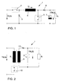
- FIG. 1 is a step-up converter as a device 1 for voltage stabilization of represented voltage fluctuation sensitive consumers R in an electrical system.
- the Device 1 comprises a clockable circuit breaker 2. Behind the circuit breaker 2 a first diode 3 connected to ground and an inductor 4 arranged downstream. Behind the Inductor 4 has a second circuit breaker 5 connected to ground. A second diode 6 and a capacitor 7 are further arranged behind the inductor 4, the capacitor 7 arranged on the output side parallel to the consumers R sensitive to voltage fluctuations.
- the capacitor 7 is preferably designed as an electrolytic capacitor.
- Means not shown further agent is the vehicle electrical system voltage U a is detected and passed to a controller, also not shown, which drives the two power switches 2 and 5.
- FIG. Corresponding to the detected vehicle electrical system voltage U a is operated, the device 1 as an up or a down converter, so that the output voltage U out is independent of the vehicle electrical system voltage U constant.
- the device 1 If the detection of the vehicle electrical system voltage U a that has these brownouts, so the device 1 is operated as a boost converter or up-converter.
- the controller not shown, closes the first circuit breaker 2.
- the second circuit breaker 5 is clocked by the controller. Due to the clocking, a time-changing current flows through the inductor 4, which induces a voltage peak at the inductor 4. As a result, the diode 6 is poled in the direction of flow and the capacitor 7 is charged. By the number of clocks can be set from the amount of the charge of the capacitor 7 and the voltage U.
- the device 1 is used as a buck converter operated.
- the second circuit breaker 5 remains open and the first circuit breaker 2 clocked.
- a time-varying current flows through the inductor 4 again induces a voltage in the inductor 4, the inductor when closed Circuit breaker 2 acts as a choke.
- the Inductance 4 as a voltage source, the circuit being closed via the first diode 3 becomes. Because of the two forward voltages across diodes 3 and 6, the resulting one Voltage at consumers R sensitive to voltage fluctuations is reduced.
- the device 1 comprises a transformer which is formed by a primary coil 8 and a secondary coil 9, with a clockable circuit breaker 10 being arranged in series with the primary coil 8.
- a diode 11 and the parallel circuit comprising a capacitor 7 and the voltage fluctuation-sensitive consumer R are arranged.
- the voltage fluctuation-sensitive consumers R are galvanically decoupled from the vehicle electrical system voltage Uein via the transformer.
- a voltage in the secondary coil 9 can then be generated as required in dependence on the vehicle electrical system voltage U, which leads to a constant voltage U from the voltage fluctuation sensitive loads R.
Landscapes
- Engineering & Computer Science (AREA)
- Power Engineering (AREA)
- Dc-Dc Converters (AREA)
- Emergency Protection Circuit Devices (AREA)
Abstract
Description
Claims (11)
- Bordnetz mit Spannungsstabilisierung, umfassend mindestens eine Spannungsquelle zur Versorgung von spannungsschwankungsunempfindlichen und spannungsschwankungsempfindlichen Verbrauchern, wobei zwischen den spannungsschwankungsempfindlichen Verbrauchern und der Spannungsquelle eine Einrichtung zur Spannungsstabilisierung angeordnet ist,
dadurch gekennzeichnet, daß
die Einrichtung (1) zur Spannungsstabilisierung Mittel zur Erfassung der Bordnetzspannung Uein umfaßt, wobei über die Einrichtung (1) in Abhängigkeit von der erfaßten Bordnetzspannung Uein Über- und Unterspannungen der Bordnetzspannung Uein ausregelbar sind. - Bordnetz nach Anspruch 1, dadurch gekennzeichnet, daß die Einrichtung (1) als transformatorischer Wandler ausgebildet ist.
- Bordnetz nach Anspruch 2, dadurch gekennzeichnet, daß in Reihe zur Primärspule (8) ein taktbarer Leistungsschalter (10) angeordnet ist, der in Abhängigkeit von der erfaßten Bordnetzspannung Uein taktbar ist.
- Bordnetz nach Anspruch 3, dadurch gekennzeichnet, daß der taktbare Leistungsschalter (10) als Halbleiterschalter ausgebildet ist.
- Bordnetz nach Anspruch 4, dadurch gekennzeichnet, daß der Halbleiter als Feldeffekttransistor ausgebildet ist.
- Bordnetz nach einem der Ansprüche 2 bis 5, dadurch gekennzeichnet, daß parallel zu den spannungsempfindlichen Verbrauchern R ein Glättungskondensator (7) oder Akkumulator angeordnet ist.
- Bordnetz nach Anspruch 6, dadurch gekennzeichnet, daß in Reihe zur Sekundärspule (9) und den spannungsempfindlichen Verbrauchern R eine Diode (11) angeordnet ist.
- Bordnetz nach Anspruch 1, dadurch gekennzeichnet, daß die Einrichtung (1) als Aufwärts- Abwärtswandler ausgebildet ist.
- Bordnetz nach Anspruch 8, dadurch gekennzeichnet, daß eingangsseitig ein taktbarer Leistungsschalter (2) angeordnet ist, zu dem in Reihe eine Parallelschaltung aus Diode (3) mit einer Induktivität (4) mit taktbarem Leistungsschalter (5) angeordnet ist, wobei parallel zu den spannungsschwankungsempfindlichen Verbrauchern R ein Glättungskondensator (7) oder Akkumulator angeordnet ist und zwischen der Parallelschaltung und der Induktivität (4) eine Diode (6) angeordnet ist.
- Bordnetz nach Anspruch 9, dadurch gekennzeichnet, daß die taktbaren Leistungsschalter (2, 5) als Halbleiterschalter ausgebildet sind.
- Bordnetz nach Anspruch 10, dadurch gekennzeichnet, daß die Halbleiterschalter als Feldeffekttransistoren ausgebildet sind.
Applications Claiming Priority (2)
| Application Number | Priority Date | Filing Date | Title |
|---|---|---|---|
| DE10019847 | 2000-04-13 | ||
| DE2000119847 DE10019847A1 (de) | 2000-04-13 | 2000-04-13 | Bordnetz mit Spannungsstabilisierung |
Publications (2)
| Publication Number | Publication Date |
|---|---|
| EP1145913A2 true EP1145913A2 (de) | 2001-10-17 |
| EP1145913A3 EP1145913A3 (de) | 2004-12-01 |
Family
ID=7639613
Family Applications (1)
| Application Number | Title | Priority Date | Filing Date |
|---|---|---|---|
| EP01250126A Ceased EP1145913A3 (de) | 2000-04-13 | 2001-04-10 | Bordnetz mit Spannungsstabilisierung |
Country Status (2)
| Country | Link |
|---|---|
| EP (1) | EP1145913A3 (de) |
| DE (1) | DE10019847A1 (de) |
Cited By (3)
| Publication number | Priority date | Publication date | Assignee | Title |
|---|---|---|---|---|
| DE102005031514A1 (de) * | 2005-07-06 | 2007-01-11 | Zf Friedrichshafen Ag | Vorrichtung zur Spannungsversorgung von elektrischen Verbrauchern in Kraftfahrzeugen |
| DE102006045730A1 (de) * | 2006-09-27 | 2008-04-03 | Zf Friedrichshafen Ag | Automatisierungs- und Betätigungseinrichtung für ein Kraftfahrzeug |
| FR2973599A1 (fr) * | 2011-03-29 | 2012-10-05 | Peugeot Citroen Automobiles Sa | Circuit electrique destine a equiper un vehicule automobile a convertisseur continu/continu pilotable en elevateur de tension, en abaisseur de tension ou en mode transparent |
Families Citing this family (4)
| Publication number | Priority date | Publication date | Assignee | Title |
|---|---|---|---|---|
| DE10163222B4 (de) * | 2001-12-21 | 2007-07-26 | Volkswagen Ag | Kraftfahrzeug-Bordnetz und Verfahren zur Überwachung der Funktionsfähigkeit desselben |
| DE102007029025A1 (de) | 2007-06-23 | 2008-12-24 | Bayerische Motoren Werke Aktiengesellschaft | Kraftfahrzeugbordnetz |
| DE102007037937A1 (de) | 2007-08-11 | 2009-02-26 | Bayerische Motoren Werke Aktiengesellschaft | Kraftfahrzeugbordnetz |
| DE102013203731A1 (de) * | 2013-03-05 | 2014-09-11 | Bayerische Motoren Werke Aktiengesellschaft | Fahrzeug-Steuergerät zur Steuerung und Versorgung eines oder mehrerer Verbraucher |
Citations (7)
| Publication number | Priority date | Publication date | Assignee | Title |
|---|---|---|---|---|
| DE3104965A1 (de) * | 1981-02-12 | 1982-08-26 | Brown, Boveri & Cie Ag, 6800 Mannheim | Gleichstrompulswandler |
| EP0573785A1 (de) * | 1992-06-09 | 1993-12-15 | Robert Bosch Gmbh | Stromversorgungsschaltung für ein Funkgerät |
| DE19511567A1 (de) * | 1995-03-29 | 1996-10-02 | Vdo Schindling | Schaltungsanordnung zur Stromversorgung einer digitalen Rechenschaltung |
| EP0779700A2 (de) * | 1995-12-11 | 1997-06-18 | Lockheed Martin Corporation | Gleichstromversorgung mit verbessertem Leistungsfaktor |
| EP0793334A1 (de) * | 1994-11-11 | 1997-09-03 | Komatsu Ltd. | Gleichstromwandler und denselben verwendende steuereinrichtung für induktive last |
| US5694303A (en) * | 1995-11-07 | 1997-12-02 | Interpoint Corporation | Semi-regulated power supply using forward converter leakage energy |
| US5903449A (en) * | 1998-06-09 | 1999-05-11 | General Electric Company | Bi-directional power control system for voltage converter |
Family Cites Families (1)
| Publication number | Priority date | Publication date | Assignee | Title |
|---|---|---|---|---|
| DE3007941A1 (de) * | 1980-03-01 | 1981-09-17 | Robert Bosch Gmbh, 7000 Stuttgart | Zweispannungs-netzanlage |
-
2000
- 2000-04-13 DE DE2000119847 patent/DE10019847A1/de not_active Withdrawn
-
2001
- 2001-04-10 EP EP01250126A patent/EP1145913A3/de not_active Ceased
Patent Citations (8)
| Publication number | Priority date | Publication date | Assignee | Title |
|---|---|---|---|---|
| DE3104965A1 (de) * | 1981-02-12 | 1982-08-26 | Brown, Boveri & Cie Ag, 6800 Mannheim | Gleichstrompulswandler |
| EP0573785A1 (de) * | 1992-06-09 | 1993-12-15 | Robert Bosch Gmbh | Stromversorgungsschaltung für ein Funkgerät |
| US5402056A (en) * | 1992-06-09 | 1995-03-28 | Robert Bosch Gmbh | Power supply for a mobile radio transceiver |
| EP0793334A1 (de) * | 1994-11-11 | 1997-09-03 | Komatsu Ltd. | Gleichstromwandler und denselben verwendende steuereinrichtung für induktive last |
| DE19511567A1 (de) * | 1995-03-29 | 1996-10-02 | Vdo Schindling | Schaltungsanordnung zur Stromversorgung einer digitalen Rechenschaltung |
| US5694303A (en) * | 1995-11-07 | 1997-12-02 | Interpoint Corporation | Semi-regulated power supply using forward converter leakage energy |
| EP0779700A2 (de) * | 1995-12-11 | 1997-06-18 | Lockheed Martin Corporation | Gleichstromversorgung mit verbessertem Leistungsfaktor |
| US5903449A (en) * | 1998-06-09 | 1999-05-11 | General Electric Company | Bi-directional power control system for voltage converter |
Cited By (3)
| Publication number | Priority date | Publication date | Assignee | Title |
|---|---|---|---|---|
| DE102005031514A1 (de) * | 2005-07-06 | 2007-01-11 | Zf Friedrichshafen Ag | Vorrichtung zur Spannungsversorgung von elektrischen Verbrauchern in Kraftfahrzeugen |
| DE102006045730A1 (de) * | 2006-09-27 | 2008-04-03 | Zf Friedrichshafen Ag | Automatisierungs- und Betätigungseinrichtung für ein Kraftfahrzeug |
| FR2973599A1 (fr) * | 2011-03-29 | 2012-10-05 | Peugeot Citroen Automobiles Sa | Circuit electrique destine a equiper un vehicule automobile a convertisseur continu/continu pilotable en elevateur de tension, en abaisseur de tension ou en mode transparent |
Also Published As
| Publication number | Publication date |
|---|---|
| EP1145913A3 (de) | 2004-12-01 |
| DE10019847A1 (de) | 2001-10-25 |
Similar Documents
| Publication | Publication Date | Title |
|---|---|---|
| DE102013106854B4 (de) | Schaltung zur Einschaltstrombegrenzung | |
| DE19545154C2 (de) | Stromversorgungseinrichtung | |
| DE19835316A1 (de) | Gesteuerte Gleichrichterbrücke mit Überspannungsschutz | |
| EP1784910A1 (de) | Spannungsregler mit überspannungsschutz | |
| DE102007040550A1 (de) | Steuerungsschema für einen Gleichstrom/Wechselstrom-Direktumrichter | |
| DE2312127A1 (de) | Elektrische drehzahlregelungseinrichtung fuer einen wechselstrommotor | |
| EP0664602B1 (de) | Sperrumrichter mit geregelter Ausgangsspannung | |
| DE3101375C2 (de) | Schaltungsanordnung zur geregelten Speisung eines Verbrauchers | |
| EP0772904B1 (de) | Vorrichtung zur spannungsversorgung mit zwei ausgangsspannungen | |
| EP1249066B1 (de) | Elektrogerät mit einem Elektromotor und einem Drosselwandler | |
| EP1145913A2 (de) | Bordnetz mit Spannungsstabilisierung | |
| DE10143726B4 (de) | Fahrzeuggeneratorsteuervorrichtung | |
| EP0799521B1 (de) | Stromversorgungsschaltung | |
| DE102019219965A1 (de) | Ladungspumpenübergangsantwortoptimierung durch gesteuerte Entladung eines fliegenden Kondensators während eines Übergangs vom Umgehungs- zum Schaltmodus | |
| DE102014225195A1 (de) | Gleichspannungswandlersystem, Gleichspannungsversorgungssystem, und Leiterplatte für ein Gleichspannungswandlersystem | |
| EP2128969A2 (de) | Schaltregler mit PWM-Regler | |
| DE112017002638T5 (de) | Schaltnetzteil | |
| DE102019201476B4 (de) | System zur elektrischen Energieübertragung | |
| EP0662277A1 (de) | Getaktete stromversorgungsschaltung. | |
| DE3914287C2 (de) | ||
| EP0978933A2 (de) | Gleichspannungswandler | |
| DE102015120658A1 (de) | Verfahren und Vorrichtung zum Steuern eines elektrischen oder elektronischen Schaltelements | |
| DE102014219787A1 (de) | Schaltnetzteil mit zumindest einem Leistungsteil und zumindest einem Hilfsnetzteil | |
| EP1885049A1 (de) | Netzteil mit kombiniertem Aufwärts/Abwärts-Schaltwandler | |
| EP2755450A2 (de) | Fernansteuerung einer Lampe |
Legal Events
| Date | Code | Title | Description |
|---|---|---|---|
| PUAI | Public reference made under article 153(3) epc to a published international application that has entered the european phase |
Free format text: ORIGINAL CODE: 0009012 |
|
| AK | Designated contracting states |
Kind code of ref document: A2 Designated state(s): AT BE CH CY DE DK ES FI FR GB GR IE IT LI LU MC NL PT SE TR |
|
| AX | Request for extension of the european patent |
Free format text: AL;LT;LV;MK;RO;SI |
|
| PUAL | Search report despatched |
Free format text: ORIGINAL CODE: 0009013 |
|
| RIC1 | Information provided on ipc code assigned before grant |
Ipc: 7H 02M 3/158 B Ipc: 7B 60R 16/02 A |
|
| AK | Designated contracting states |
Kind code of ref document: A3 Designated state(s): AT BE CH CY DE DK ES FI FR GB GR IE IT LI LU MC NL PT SE TR |
|
| AX | Request for extension of the european patent |
Extension state: AL LT LV MK RO SI |
|
| 17P | Request for examination filed |
Effective date: 20050601 |
|
| AKX | Designation fees paid |
Designated state(s): DE ES FR GB IT |
|
| STAA | Information on the status of an ep patent application or granted ep patent |
Free format text: STATUS: THE APPLICATION HAS BEEN REFUSED |
|
| 18R | Application refused |
Effective date: 20090626 |