EP1145350B1 - Verfahren zur regelung der brennstoffkonzentration in einem alkohol oder ether als brennstoff und wasser enthaltenden brennstoffgemisch einer brennstoffzelle und brennstoffzellensystem - Google Patents
Verfahren zur regelung der brennstoffkonzentration in einem alkohol oder ether als brennstoff und wasser enthaltenden brennstoffgemisch einer brennstoffzelle und brennstoffzellensystem Download PDFInfo
- Publication number
- EP1145350B1 EP1145350B1 EP99960804A EP99960804A EP1145350B1 EP 1145350 B1 EP1145350 B1 EP 1145350B1 EP 99960804 A EP99960804 A EP 99960804A EP 99960804 A EP99960804 A EP 99960804A EP 1145350 B1 EP1145350 B1 EP 1145350B1
- Authority
- EP
- European Patent Office
- Prior art keywords
- fuel
- mixture
- measurement
- concentration
- fuel cell
- Prior art date
- Legal status (The legal status is an assumption and is not a legal conclusion. Google has not performed a legal analysis and makes no representation as to the accuracy of the status listed.)
- Expired - Lifetime
Links
Images
Classifications
-
- H—ELECTRICITY
- H01—ELECTRIC ELEMENTS
- H01M—PROCESSES OR MEANS, e.g. BATTERIES, FOR THE DIRECT CONVERSION OF CHEMICAL ENERGY INTO ELECTRICAL ENERGY
- H01M8/00—Fuel cells; Manufacture thereof
- H01M8/04—Auxiliary arrangements, e.g. for control of pressure or for circulation of fluids
- H01M8/04082—Arrangements for control of reactant parameters, e.g. pressure or concentration
- H01M8/04186—Arrangements for control of reactant parameters, e.g. pressure or concentration of liquid-charged or electrolyte-charged reactants
- H01M8/04194—Concentration measuring cells
-
- H—ELECTRICITY
- H01—ELECTRIC ELEMENTS
- H01M—PROCESSES OR MEANS, e.g. BATTERIES, FOR THE DIRECT CONVERSION OF CHEMICAL ENERGY INTO ELECTRICAL ENERGY
- H01M8/00—Fuel cells; Manufacture thereof
- H01M8/10—Fuel cells with solid electrolytes
- H01M8/1009—Fuel cells with solid electrolytes with one of the reactants being liquid, solid or liquid-charged
-
- Y—GENERAL TAGGING OF NEW TECHNOLOGICAL DEVELOPMENTS; GENERAL TAGGING OF CROSS-SECTIONAL TECHNOLOGIES SPANNING OVER SEVERAL SECTIONS OF THE IPC; TECHNICAL SUBJECTS COVERED BY FORMER USPC CROSS-REFERENCE ART COLLECTIONS [XRACs] AND DIGESTS
- Y02—TECHNOLOGIES OR APPLICATIONS FOR MITIGATION OR ADAPTATION AGAINST CLIMATE CHANGE
- Y02E—REDUCTION OF GREENHOUSE GAS [GHG] EMISSIONS, RELATED TO ENERGY GENERATION, TRANSMISSION OR DISTRIBUTION
- Y02E60/00—Enabling technologies; Technologies with a potential or indirect contribution to GHG emissions mitigation
- Y02E60/30—Hydrogen technology
- Y02E60/50—Fuel cells
Definitions
- the invention relates to a method for regulating the fuel concentration in one Fuel mixture for a fuel cell made from an alcohol or an ether Fuel and water is formed, and a fuel cell system containing at least one with an alcohol or an ether as fuel and water Fuel cell operated fuel cell, and at least one with one each controllable fuel inlet connected mixing room and at least one, the at least a mixing room each connecting the at least one fuel cell Fuel mixture supply line.
- Fuel cell systems of the type mentioned in the introduction have been known for more than 30 years at the time of this application (see, for example, W. Dahlstich; “Fuel Elements “ Verlag Chemie, Weinheim 1965, pages 73-93 and L. Oniciu; “Fuel Cells", Abacus-Press, Kent , 1976, pages 93-98).
- the alcohol eg methanol
- the alcohol is added to a fuel cell as a fuel and mixed with water to form a fuel mixture, where it is immediately converted into electrical energy.
- Alcohol contents between 1% by volume and 5% by volume in the fuel mixture have proven to be particularly favorable for the operation of such a fuel cell.
- One problem with the operation of such fuel cells is to keep the alcohol concentration of the fuel mixture as constant as possible. This applies in the same way to alcohol as to fuel cells using ether as fuel.
- DE 197 01 560 A1 discloses a fuel cell system in which a liquid Fuel mixture consisting of a fuel and a coolant in the anode compartment is supplied to a fuel cell.
- DE 196 28 888 C1 discloses a fuel cell which can be operated with a fuel mixture of fuel and water, among other things. The efficiency of the fuel cell is increased by an alternating operating pressure.
- DE 44 25 634 C1 describes a method and a device for the metered feeding of Methanol and / or water from a storage container via a delivery line to a fuel cell system known.
- the regulation is thus achieved in that the fuel concentration in the fuel mixture but is determined in a measuring mixture in which the fuel concentrations is in an area with sufficient accuracy and speed known sensors is measurable.
- the fuel concentration in the measuring mixture is immediate depending on the fuel concentration in the fuel mixture, so that its regulation by Measurements of the fuel content in the measuring mixture are possible.
- the method according to the invention can be carried out in such a way that a carrier liquid or a carrier gas for dilution and / or removal of the permeated fuel is used in the measuring chamber to produce the measuring mixture.
- the permeated fuel can also be consumed at electrodes in the measuring chamber, so that the removal of the fuel by the carrier liquid or the carrier gas is not mandatory.
- the specified fuel concentrations can be achieved even without a carrier liquid or carrier gas: the membrane can be more permeable to the fuel by more than an order of magnitude than water, so that a measuring mixture of the permeated fuel and the permeated water forms in the measuring chamber a fuel concentration of less than 1 vol .-% down in the ppm range.
- permeability of the membrane to water is higher than to the fuel
- measurement mixtures can form in which the fuel concentration is above 5, preferably above 10,% by volume.
- Membranes suitable for this purpose are known (see, for example, H. Strahtmann; “Membrans and Membrane Separation processes", B. Elvers, S. Hawkins, G. Schulz (Ed.); “ Ullmanns Encyclopedia of Industrial Chemistry", Vol. A 16. VCH , Weinheim, 1990, pages 187-263 ).
- the inventive method can also be carried out so that the Fuel concentration of the measuring mixture in the case of values above 10 or 5% by volume is determined by means of a liquid sensor.
- the inventive method can also be carried out so that the fuel concentration of the measuring mixture is determined by means of density or viscosity measurements.
- the inventive method can also be carried out so that the fuel concentration of the measuring mixture by means of optical methods, for. B. is determined by means of infrared absorption.
- Optical sensors suitable for this, in particular for evaluating the CH vibrations of the fuel are also known (see, for example, A. Brittain et al. (Ed.) "Optically Based Methods for Process Analysis", S. PIE Proceedings Vol. 1681, Somerset , NJ, USA, 1992 ) .
- the method according to the invention can also be carried out in such a way that the fuel concentration of the measuring mixture in the case of values below 1.0 or 0.1% by volume is determined by means of a gas sensor.
- a gas sensor has a semiconductor element that changes its electrical properties as a function of the concentration of the fuel.
- Such a gas sensor and its use in a measuring chamber delimited by a silicone membrane are also known in connection with bioreactors (see FMC manual from Biotechnologie Kempe GmbH, Berlin). It is also possible to determine this by recording the conductivity and by infrared absorption.
- the invention further provides that a gas, liquid, infrared absorption, Density measurement, optical or conductivity measurement sensor is provided.
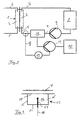
- the fuel cell system using methanol as fuel according to FIG. 1 comprises a Fuel cell 1 with a fuel chamber 2 and a reaction substance chamber 3 Fuel mixture feed line 4, the fuel chamber 2 is made up of methanol and water Fuel mixture supplied, the methanol concentration in the fuel mixture is about 4% by volume.
- the reactant chamber 3 is air via a reactant feed fed.
- the exhaust gas, a water-air mixture, is removed from the reaction substance chamber via the exhaust gas discharge line 6 3 dissipated.
- a return pump 9 is connected to the intermediate supply 8, via which the Methanol content reduced fuel mixture in the fuel mixture feed line 4 and thus to Fuel chamber 2 is pumped. The fuel mixture is thus circulated.
- the fuel mixture entering the fuel chamber 2 has the required methanol concentration can be from a methanol supply 10 via a methanol pump 11 Pumped methanol into a mixing room 12, where it was reduced with that in the methanol content Fuel mixture from the intermediate supply 8 mixed.
- the mixing space 12 is in FIG. 1 shown symbolically enlarged, but can actually only a part of the fuel mixture supply line 4.
- the pumping capacity of the methanol pump 11 can be controlled.
- the methanol concentration is regulated. Therefor a variable that is directly dependent on the methanol concentration in the fuel mixture is measured.
- FIG. 2 the area circled in dashed lines in FIG. 1 is shown enlarged.
- Fig. 2 shows a measuring probe 13 which is placed on the fuel mixture feed line 4.
- the measuring probe 13 has a membrane 14 which is in direct contact with the fuel mixture flowing past Contact is there.
- the membrane 14 is so selectively permeable to water and methanol that in a measuring chamber delimited by the walls 15 of the measuring probe 13 and the membrane 14 16 a measuring mixture consisting of water and methanol with a methanol content in the ppm range.
- a methanol sensor 17 which is in this Concentration range is highly effective.
- the methanol sensor 17 as a function of The measured quantity of the methanol concentration in the measuring mixture is applied via the measuring line 18 a controller 19 (Fig. 1) passed on, the methanol pump 11 thus depending on controls the methanol concentration in the measuring mixture. Since the methanol concentration in the measuring mixture directly from the methanol concentration in the fuel mixture in the fuel feed line 4 depends on the location of the measuring probe 13, the methanol concentration in the The fuel mixture can be kept largely constant.
Landscapes
- Life Sciences & Earth Sciences (AREA)
- Engineering & Computer Science (AREA)
- Manufacturing & Machinery (AREA)
- Sustainable Development (AREA)
- Sustainable Energy (AREA)
- Chemical & Material Sciences (AREA)
- Chemical Kinetics & Catalysis (AREA)
- Electrochemistry (AREA)
- General Chemical & Material Sciences (AREA)
- Fuel Cell (AREA)
- Investigating Or Analysing Materials By Optical Means (AREA)
- Separation Using Semi-Permeable Membranes (AREA)
- Liquid Carbonaceous Fuels (AREA)
Description
- Fig. 1:
- den Aufbau eines Methanol als Brennstoff verwendendes Brennstoffzellensystems und
- Fig. 2:
- einen vergrößerten Ausschnitt aus der Anordnung gemäß Fig. 1 mit einer an eine Brennstoffgemischzuleitung angekoppelten Meßsonde.
- 1
- Brennstoffzelle
- 2
- Brennstoffkammer
- 3
- Reaktionsstoffkammer
- 4
- Brennstoffgemischzuleitung
- 5
- Reaktionsstoffzuleitung
- 6
- Abgasableitung
- 7
- Restbrennstoffableitung
- 8
- Zwischenvorrat
- 9
- Rückführpumpe
- 10
- Methanolvorrat
- 11
- Methanolpumpe
- 12
- Mischraum
- 13
- Meßsonde
- 14
- Membran
- 15
- Wand
- 16
- Meßkammer
- 17
- Methanolsensor
- 18
- Meßleitung
- 19
- Regler
Claims (13)
- Verfahren zur Regelung der Brennstoffkonzentration in einem Brennstoffgemisch für eine Brennstoffzelle, das von einem Alkohol oder einem Ether als Brennstoff und Wasser gebildet wird, dadurch gekennzeichnet, daß
der Brennstoff über einen steuerbaren Brennstoffeinlaß (11) einem Mischraum (12) zugeführt wird, von wo aus das Brennstoffgemisch über eine Brennstoffgemischzuleitung (4) der Brennstoffzelle (1) über eine in Fließrichtung hinter dem Brennstoffeinlaß (11) angeordnete, eine Meßkammer (16) begrenzende, für Wasser und den Brennstoff selektiv permeable Membran (14) zugeführt wird, wobei in der Meßkammer (16) ein flüssiges oder gasförmiges Meßgemisch mit einer, von der aus dem Brennstoffgemisch pro Zeiteinheit in die Meßkammer (16) permeierten Brennstoffmenge abhängigen Brennstoffkonzentration von weniger als 1 Vol.-% oder mehr als 5 Vol.-% hergestellt wird, worauf die Brennstoffkonzentration im Meßgemisch ermittelt und der Brennstoffeinlaß (11) in Abhängigkeit von der Brennstoffkonzentration im Meßgemisch gesteuert wird. - Verfahren nach Anspruch 1, dadurch gekennzeichnet, daß in der Meßkammer (16) ein flüssiges oder gasförmiges Meßgemisch mit einer von der aus dem Brennstoffgemisch pro Zeiteinheit in die Meßkammer (16) permeierten Brennstoffmenge abhängigen Brennstoffkonzentration von weniger als 0,1 Vol.-% hergestellt wird.
- Verfahren nach Anspruch 1, dadurch gekennzeichnet, daß in der Meßkammer (16) ein flüssiges oder gasförmiges Meßgemisch mit einer von der aus dem Brennstoffgemisch pro Zeiteinheit in die Meßkammer (16) permeierten Brennstoffmenge abhängigen Brennstoffkonzentration von mehr als 10 Vol.-% hergestellt wird.
- Verfahren nach einem der vorhergehenden Ansprüche, dadurch gekennzeichnet, daß zur Herstellung des Meßgemischs in der Meßkammer (16) eine Trägerflüssigkeit oder ein Trägergas zur Verdünnung und/oder Entfernung des permeierten Brennstoffs eingesetzt wird.
- Verfahren nach einem der vorhergehenden Ansprüche, dadurch gekennzeichnet, daß die Brennstoffkonzentration des Meßgemischs im Falle von Werten oberhalb 10 oder 5 Vol.-% mittels eines Flüssigkeitssensors bestimmt wird.
- Verfahren nach Anspruch 5, dadurch gekennzeichnet, daß die Brennstoffkonzentration des Meßgemischs mittels Dichte- oder Viskositätsmessungen bestimmt wird.
- Verfahren nach Anspruch 5, dadurch gekennzeichnet, daß die Brennstoffkonzentration des Meßgemischs mittels optischer Verfahren bestimmt wird.
- Verfahren Anspruch 7, dadurch gekennzeichnet, daß die Brennstoffkonzentration des Meßgemischs mittels Infrarotabsorbtion bestimmt wird.
- Verfahren nach einem der Ansprüche 1 bis 4, dadurch gekennzeichnet, daß die Brennstoffkonzentration des Meßgemischs im Falle von Werten unterhalb 1,0 oder 0,1 Vol.-% mittels eines Gassensors bestimmt wird.
- Verfahren nach Anspruch 9, dadurch gekennzeichnet, daß die Brennstoffkonzentration des Meßgemischs mittels optischer Verfahren oder durch Erfassung der Leitfähigkeit bestimmt wird.
- Verfahren Anspruch 9, dadurch gekennzeichnet, daß die Brennstoffkonzentration des Meßgemischs mittels Infrarotabsorbtion bestimmt wird.
- Brennstoffzellensystem, enthaltend mindestens eine, mit einem aus einem Alkohol oder einem Ether als Brennstoff und Wasser bestehenden Brennstoffgemisch betreibbare Brennstoffzelle (1), sowie mindestens einen mit jeweils einem steuerbaren Brennstoffeinlaß (11) verbundenen Mischraum (12) und mindestens eine, den mindestens einen Mischraum (12) jeweils mit der mindestens einen Brennstoffzelle (1) verbindende Brennstoffgemischzuleitung (4),
dadurch gekennzeichnet, daß
das Brennstoffzellensystem mindestens eine in Fließrichtung des Brennstoffgemisches hinter dem Brennstoffeinlaß (11) angeordnete Meßsonde (13) aufweist, die ausund daß das Brennstoffzellensystem Mittel (19) zur Steuerung des Brennstoffeinlasses (11) in Abhängigkeit von der Brennstoffkonzentration im Meßgemisch aufweist.a) einer Meßkammer (16),b) einer die Meßkammer (16) begrenzenden, mit dem Brennstoffgemisch in Kontakt stehenden, für den Brennstoff und/oder Wasser selektiv permeablen Membran (14), die zur Erzeugung eines flüssigen oder gasförmigen Meßgemisches mit einer von der aus dem Brennstoffgemisch pro Zeiteinheit in die Meßkammer (16) permeierten Brennstoffmenge abhängigen Brennstoffkonzentration von weniger als 1 Vol.-% oder mehr als 5 Vol.-% dient, undc) einem Sensor (17) zur Bestimmung der Brennstoffkonzentration im Meßgemisch besteht, - Brennstoffzellensystem nach Anspruch 12, dadurch gekennzeichnet, daß als Sensor (17) ein Gas-, Flüssigkeits-, Infrarotabsorptions-, Dichtemessungs-, optischer oder Leitfähigkeitmessungs-Sensor vorgesehen ist.
Applications Claiming Priority (3)
| Application Number | Priority Date | Filing Date | Title |
|---|---|---|---|
| DE19850720A DE19850720C2 (de) | 1998-11-03 | 1998-11-03 | Verfahren zur Regelung der Brennstoffkonzentration in einem Alkohol oder Ether als Brennstoff und Wasser enthaltenden Brennstoffgemisch einer Brennstoffzelle und Brennstoffzellensystem |
| DE19850720 | 1998-11-03 | ||
| PCT/DE1999/003384 WO2000026978A2 (de) | 1998-11-03 | 1999-10-22 | Verfahren zur regelung der brennstoffkonzentration in einem alkohol oder ether als brennstoff und wasser enthaltenden brennstoffgemisch einer brennstoffzelle und brennstoffzellensystem |
Publications (2)
| Publication Number | Publication Date |
|---|---|
| EP1145350A2 EP1145350A2 (de) | 2001-10-17 |
| EP1145350B1 true EP1145350B1 (de) | 2002-12-18 |
Family
ID=7886587
Family Applications (1)
| Application Number | Title | Priority Date | Filing Date |
|---|---|---|---|
| EP99960804A Expired - Lifetime EP1145350B1 (de) | 1998-11-03 | 1999-10-22 | Verfahren zur regelung der brennstoffkonzentration in einem alkohol oder ether als brennstoff und wasser enthaltenden brennstoffgemisch einer brennstoffzelle und brennstoffzellensystem |
Country Status (6)
| Country | Link |
|---|---|
| EP (1) | EP1145350B1 (de) |
| AT (1) | ATE230163T1 (de) |
| AU (1) | AU756379B2 (de) |
| CA (1) | CA2348861A1 (de) |
| DE (2) | DE19850720C2 (de) |
| WO (1) | WO2000026978A2 (de) |
Families Citing this family (10)
| Publication number | Priority date | Publication date | Assignee | Title |
|---|---|---|---|---|
| DE19945931A1 (de) * | 1999-09-24 | 2001-05-03 | Siemens Ag | Bestimmung der Alkoholkonzentration im Elektrolyt von Brennstoffzellen |
| DE19948908C2 (de) * | 1999-10-11 | 2001-10-04 | Siemens Ag | Verfahren zur Bestimmung der Alkoholkonzentration in Brennstoffzellen sowie ein zu dessen Durchführung geeignetes Brennstoffzellensystem |
| DE10015331A1 (de) * | 2000-03-28 | 2001-10-04 | Volkswagen Ag | Vorrichtung zur Zuführung eines Brennstoffgemischs in eine Brennstoffzelle |
| DE10015334A1 (de) * | 2000-03-28 | 2001-10-04 | Volkswagen Ag | Vorrichtung zur Zuführung eines Brennstoffgemischs in eine Brennstoffzelle und entsprechendes Verfahren |
| DE10029481C2 (de) * | 2000-06-15 | 2002-06-13 | Mannesmann Ag | Vorrichtung zum Zuleiten von Brennstoff in die Brennstoffzelle eines Brennstoffzellensystems sowie Brennstoffzellensystem |
| DE10314605A1 (de) * | 2002-07-26 | 2004-02-05 | Daimlerchrysler Ag | Anordnung und Verfahren zur optischen Messung von Wasser in einer Membran-Elektroden-Anordnung |
| JP3878092B2 (ja) * | 2002-08-30 | 2007-02-07 | ヤマハ発動機株式会社 | 直接改質型燃料電池システム |
| DE102005010497B4 (de) | 2005-03-08 | 2014-05-28 | Forschungszentrum Jülich GmbH | Verfahren zum Betreiben eines Direkt-Methanol-Brennstoffzellenstapels |
| DE102007050616B3 (de) * | 2007-10-23 | 2009-04-09 | Fraunhofer-Gesellschaft zur Förderung der angewandten Forschung e.V. | Passive Verdünnungseinheit zur Verdünnung von Brennstoffen |
| DE102019218907A1 (de) * | 2019-12-04 | 2021-06-10 | Forschungszentrum Jülich GmbH | Verfahren und Vorrichtung zur Erzeugung von elektrischem Strom sowie Verwendung einer organischen Verbindung zur Erzeugung von elektrischem Strom |
Family Cites Families (9)
| Publication number | Priority date | Publication date | Assignee | Title |
|---|---|---|---|---|
| US3425873A (en) * | 1963-12-19 | 1969-02-04 | Exxon Research Engineering Co | Process of automatically controlling fuel concentration in fuel cell |
| DE1902481A1 (de) * | 1969-01-18 | 1970-08-13 | Varta Ag | Verfahren zur Regelung der Alkoholkonzentration im Elektrolyten von Brennstoffelementen und dafuer geeignete Vorrichtungen |
| JPS56118273A (en) * | 1980-02-20 | 1981-09-17 | Nissan Motor Co Ltd | Concentration sensor for fuel cell |
| JPS60189174A (ja) * | 1984-03-07 | 1985-09-26 | Hitachi Ltd | 燃料電池 |
| US4629664A (en) * | 1984-10-31 | 1986-12-16 | Hitachi, Ltd. | Liquid fuel cell |
| JPS6355864A (ja) * | 1986-08-27 | 1988-03-10 | Hitachi Ltd | 燃料電池の燃料検出装置 |
| DE4425634C1 (de) * | 1994-07-20 | 1995-10-26 | Daimler Benz Ag | Verfahren und Vorrichtung zum dosierten Zuführen von flüssigen Reaktanden zu einem Brennstoffzellensystem |
| DE19628888C1 (de) * | 1996-07-17 | 1998-01-15 | Siemens Ag | Brennstoffzelle mit erhöhter Durchmischung in den Elektrodenporen und Verfahren zum Betreiben einer solchen Brennstoffzelle mit alternierendem Betriebsdruck |
| DE19701560C2 (de) * | 1997-01-17 | 1998-12-24 | Dbb Fuel Cell Engines Gmbh | Brennstoffzellensystem |
-
1998
- 1998-11-03 DE DE19850720A patent/DE19850720C2/de not_active Expired - Fee Related
-
1999
- 1999-10-22 CA CA002348861A patent/CA2348861A1/en not_active Abandoned
- 1999-10-22 AU AU17689/00A patent/AU756379B2/en not_active Ceased
- 1999-10-22 AT AT99960804T patent/ATE230163T1/de active
- 1999-10-22 DE DE59903884T patent/DE59903884D1/de not_active Expired - Lifetime
- 1999-10-22 WO PCT/DE1999/003384 patent/WO2000026978A2/de not_active Ceased
- 1999-10-22 EP EP99960804A patent/EP1145350B1/de not_active Expired - Lifetime
Also Published As
| Publication number | Publication date |
|---|---|
| AU756379B2 (en) | 2003-01-09 |
| WO2000026978A2 (de) | 2000-05-11 |
| AU1768900A (en) | 2000-05-22 |
| DE19850720A1 (de) | 2000-05-04 |
| DE19850720C2 (de) | 2001-06-21 |
| EP1145350A2 (de) | 2001-10-17 |
| DE59903884D1 (de) | 2003-01-30 |
| CA2348861A1 (en) | 2000-05-11 |
| ATE230163T1 (de) | 2003-01-15 |
| WO2000026978A3 (de) | 2002-10-24 |
Similar Documents
| Publication | Publication Date | Title |
|---|---|---|
| EP0670490B1 (de) | Verfahren und Vorrichtung zum Messen eines Gasmediums mit einem chemischen Sensor | |
| DE102007059737B4 (de) | Verfahren zur Bestimmung des Anodenabgasablasses sowie dazugehöriges Brennstoffzellensystem | |
| DE69921457T2 (de) | Brennstoffemulsion mischsystem | |
| DE102009019838B4 (de) | Brennstoffzellensystem und Verfahren zum Bestimmen der Drehzahl einer Rezirkulationspumpe in einem Anodenrezirkulationskreislauf eines Brennstoffzellensystems | |
| DE102008047389B4 (de) | Brennstoffzellensystem und Verfahren zur Online-Bestimmung und Verfahren zum Steuern der relativen Feuchtigkeit eines Reaktandenstroms in einem Brennstoffzellenstapel | |
| DE2408378C3 (de) | Verfahren und Vorrichtung zum Füllen eines Hochdruckbehälters mit einem geeichten Gasgemisch | |
| EP0049887B1 (de) | Verfahren und Einrichtung zur Erfassung von biologisch abbaubaren und toxischen Inhaltsstoffen in wässrigen Lösungen, z.B. Abwasser | |
| DE102012218132A1 (de) | Anodenspül- und Ablassventilstrategie für ein Brennstoffzellensystem | |
| DE2137073A1 (de) | Vorrichtung und Verfahren zur Be Stimmung der Elektroaktivitat eines wass rigen Musters | |
| DE19850720C2 (de) | Verfahren zur Regelung der Brennstoffkonzentration in einem Alkohol oder Ether als Brennstoff und Wasser enthaltenden Brennstoffgemisch einer Brennstoffzelle und Brennstoffzellensystem | |
| AT521823B1 (de) | Ermittlung des Massenstromes eines Abgasbestandteils einer Brennstoffzelle | |
| DE102015103981A1 (de) | Steuerung eines Brennstoffzellensystems unter Verwendung eines abgeleiteten Luftmassenflusses | |
| DE102011011147A1 (de) | Verfahren zur detektion eines phasenübergangs einer mündungsströmung in einer druckgesteuerten anode | |
| EP0314731B1 (de) | Einrichtung für die herstellung bestimmter konzentrationen gasförmiger stoffe sowie zum mischen verschiedener gasförmiger stoffe in einem vorgegebenen verhältnis | |
| DE2136035A1 (de) | Verfahren zum entfernen kolloidaler stoffe aus einer fluessigkeit und vorrichtung zur durchfuehrung des verfahrens, insbesondere bei der abwasserreinigung | |
| DE2147725A1 (de) | Vorrichtung zum Bestimmen des Sauerstoffbedarfs in Flüssigkeitsproben | |
| DE2617174A1 (de) | Vorrichtung zum bestimmen der sauerstoffzehrung in fluessigkeiten | |
| EP0411500A1 (de) | Vorrichtung zum Herstellen von Gas/Dampf-Gemischen | |
| EP0831151B1 (de) | Verfahren und Vorrichtung zur Messung der Nitrifikationsleistung von Belebtschlamm | |
| DE102016125399A1 (de) | Energiewandler-Oxidationsmessanlage und Energiewandler-Oxidationsmessverfahren für eine Messung eines Oxidationsverhaltens eines Prüflings | |
| EP1252677A2 (de) | Dosiereinheit und verfahren zur dosierung flüssiger oder gasförmiger edukte für ein brennstoffzellensystem | |
| EP1977233A1 (de) | Verfahren und vorrichtung zum messen der konzentration eines gasbestandteils in einem gasgemisch | |
| DE3934025A1 (de) | Verfahren zur kontinuierlichen bestimmung von dimethylformamid und dimethylamin in waessrigen loesungen, insbesondere in abwaessern | |
| EP3173784A1 (de) | Gasmessanordnung mit prüfgaserzeugungseinheit | |
| DE102006031206A1 (de) | Verfahren zur Herstellung eines Kalibrieraerosols für die Anzahlkonzentration luftgetragener Partikeln und Kalibrieraerosolgenerator |
Legal Events
| Date | Code | Title | Description |
|---|---|---|---|
| PUAI | Public reference made under article 153(3) epc to a published international application that has entered the european phase |
Free format text: ORIGINAL CODE: 0009012 |
|
| 17P | Request for examination filed |
Effective date: 20010509 |
|
| AK | Designated contracting states |
Kind code of ref document: A2 Designated state(s): AT BE CH CY DE DK ES FI FR GB GR IE IT LI LU MC NL PT SE |
|
| XX | Miscellaneous (additional remarks) |
Free format text: DERZEIT SIND DIE WIPO-PUBLIKATIONSDATEN A3 NICHT VERFUEGBAR. |
|
| GRAG | Despatch of communication of intention to grant |
Free format text: ORIGINAL CODE: EPIDOS AGRA |
|
| 17Q | First examination report despatched |
Effective date: 20020214 |
|
| GRAG | Despatch of communication of intention to grant |
Free format text: ORIGINAL CODE: EPIDOS AGRA |
|
| GRAH | Despatch of communication of intention to grant a patent |
Free format text: ORIGINAL CODE: EPIDOS IGRA |
|
| RAP1 | Party data changed (applicant data changed or rights of an application transferred) |
Owner name: FORSCHUNGSZENTRUM JUELICH GMBH |
|
| GRAH | Despatch of communication of intention to grant a patent |
Free format text: ORIGINAL CODE: EPIDOS IGRA |
|
| PUAK | Availability of information related to the publication of the international search report |
Free format text: ORIGINAL CODE: 0009015 |
|
| GRAA | (expected) grant |
Free format text: ORIGINAL CODE: 0009210 |
|
| AK | Designated contracting states |
Kind code of ref document: A3 Designated state(s): AT BE CH CY DE DK ES FI FR GB GR IE IT LI LU MC NL PT SE |
|
| AK | Designated contracting states |
Kind code of ref document: B1 Designated state(s): AT BE CH CY DE DK ES FI FR GB GR IE IT LI LU MC NL PT SE |
|
| PG25 | Lapsed in a contracting state [announced via postgrant information from national office to epo] |
Ref country code: NL Free format text: LAPSE BECAUSE OF FAILURE TO SUBMIT A TRANSLATION OF THE DESCRIPTION OR TO PAY THE FEE WITHIN THE PRESCRIBED TIME-LIMIT Effective date: 20021218 Ref country code: IT Free format text: LAPSE BECAUSE OF FAILURE TO SUBMIT A TRANSLATION OF THE DESCRIPTION OR TO PAY THE FEE WITHIN THE PRESCRIBED TIME-LIMIT;WARNING: LAPSES OF ITALIAN PATENTS WITH EFFECTIVE DATE BEFORE 2007 MAY HAVE OCCURRED AT ANY TIME BEFORE 2007. THE CORRECT EFFECTIVE DATE MAY BE DIFFERENT FROM THE ONE RECORDED. Effective date: 20021218 Ref country code: GR Free format text: LAPSE BECAUSE OF FAILURE TO SUBMIT A TRANSLATION OF THE DESCRIPTION OR TO PAY THE FEE WITHIN THE PRESCRIBED TIME-LIMIT Effective date: 20021218 Ref country code: FI Free format text: LAPSE BECAUSE OF FAILURE TO SUBMIT A TRANSLATION OF THE DESCRIPTION OR TO PAY THE FEE WITHIN THE PRESCRIBED TIME-LIMIT Effective date: 20021218 |
|
| REF | Corresponds to: |
Ref document number: 230163 Country of ref document: AT Date of ref document: 20030115 Kind code of ref document: T |
|
| REG | Reference to a national code |
Ref country code: GB Ref legal event code: FG4D Free format text: NOT ENGLISH |
|
| XX | Miscellaneous (additional remarks) |
Free format text: DERZEIT SIND DIE WIPO-PUBLIKATIONSDATEN A3 NICHT VERFUEGBAR. |
|
| REG | Reference to a national code |
Ref country code: CH Ref legal event code: EP |
|
| REG | Reference to a national code |
Ref country code: IE Ref legal event code: FG4D Free format text: GERMAN |
|
| REF | Corresponds to: |
Ref document number: 59903884 Country of ref document: DE Date of ref document: 20030130 Kind code of ref document: P Ref document number: 59903884 Country of ref document: DE Date of ref document: 20030130 |
|
| PG25 | Lapsed in a contracting state [announced via postgrant information from national office to epo] |
Ref country code: SE Free format text: LAPSE BECAUSE OF FAILURE TO SUBMIT A TRANSLATION OF THE DESCRIPTION OR TO PAY THE FEE WITHIN THE PRESCRIBED TIME-LIMIT Effective date: 20030318 Ref country code: PT Free format text: LAPSE BECAUSE OF FAILURE TO SUBMIT A TRANSLATION OF THE DESCRIPTION OR TO PAY THE FEE WITHIN THE PRESCRIBED TIME-LIMIT Effective date: 20030318 Ref country code: DK Free format text: LAPSE BECAUSE OF FAILURE TO SUBMIT A TRANSLATION OF THE DESCRIPTION OR TO PAY THE FEE WITHIN THE PRESCRIBED TIME-LIMIT Effective date: 20030318 |
|
| GBT | Gb: translation of ep patent filed (gb section 77(6)(a)/1977) |
Effective date: 20030228 |
|
| REG | Reference to a national code |
Ref country code: CH Ref legal event code: NV Representative=s name: E. BLUM & CO. PATENTANWAELTE |
|
| PG25 | Lapsed in a contracting state [announced via postgrant information from national office to epo] |
Ref country code: ES Free format text: LAPSE BECAUSE OF FAILURE TO SUBMIT A TRANSLATION OF THE DESCRIPTION OR TO PAY THE FEE WITHIN THE PRESCRIBED TIME-LIMIT Effective date: 20030627 |
|
| ET | Fr: translation filed | ||
| PG25 | Lapsed in a contracting state [announced via postgrant information from national office to epo] |
Ref country code: CY Free format text: LAPSE BECAUSE OF FAILURE TO SUBMIT A TRANSLATION OF THE DESCRIPTION OR TO PAY THE FEE WITHIN THE PRESCRIBED TIME-LIMIT Effective date: 20031022 |
|
| PLBE | No opposition filed within time limit |
Free format text: ORIGINAL CODE: 0009261 |
|
| STAA | Information on the status of an ep patent application or granted ep patent |
Free format text: STATUS: NO OPPOSITION FILED WITHIN TIME LIMIT |
|
| 26N | No opposition filed |
Effective date: 20030919 |
|
| REG | Reference to a national code |
Ref country code: CH Ref legal event code: PFA Owner name: FORSCHUNGSZENTRUM JUELICH GMBH Free format text: FORSCHUNGSZENTRUM JUELICH GMBH# #52425 JUELICH (DE) -TRANSFER TO- FORSCHUNGSZENTRUM JUELICH GMBH# #52425 JUELICH (DE) |
|
| PGFP | Annual fee paid to national office [announced via postgrant information from national office to epo] |
Ref country code: LU Payment date: 20111024 Year of fee payment: 13 Ref country code: MC Payment date: 20111021 Year of fee payment: 13 |
|
| PG25 | Lapsed in a contracting state [announced via postgrant information from national office to epo] |
Ref country code: MC Free format text: LAPSE BECAUSE OF NON-PAYMENT OF DUE FEES Effective date: 20121031 |
|
| PG25 | Lapsed in a contracting state [announced via postgrant information from national office to epo] |
Ref country code: LU Free format text: LAPSE BECAUSE OF NON-PAYMENT OF DUE FEES Effective date: 20121022 |
|
| REG | Reference to a national code |
Ref country code: FR Ref legal event code: PLFP Year of fee payment: 17 |
|
| PGFP | Annual fee paid to national office [announced via postgrant information from national office to epo] |
Ref country code: GB Payment date: 20151026 Year of fee payment: 17 Ref country code: DE Payment date: 20150910 Year of fee payment: 17 Ref country code: IE Payment date: 20151022 Year of fee payment: 17 Ref country code: CH Payment date: 20151026 Year of fee payment: 17 |
|
| PGFP | Annual fee paid to national office [announced via postgrant information from national office to epo] |
Ref country code: FR Payment date: 20151026 Year of fee payment: 17 Ref country code: BE Payment date: 20151022 Year of fee payment: 17 Ref country code: AT Payment date: 20151022 Year of fee payment: 17 |
|
| PG25 | Lapsed in a contracting state [announced via postgrant information from national office to epo] |
Ref country code: BE Free format text: LAPSE BECAUSE OF NON-PAYMENT OF DUE FEES Effective date: 20161031 |
|
| REG | Reference to a national code |
Ref country code: DE Ref legal event code: R119 Ref document number: 59903884 Country of ref document: DE |
|
| REG | Reference to a national code |
Ref country code: CH Ref legal event code: PL |
|
| REG | Reference to a national code |
Ref country code: AT Ref legal event code: MM01 Ref document number: 230163 Country of ref document: AT Kind code of ref document: T Effective date: 20161022 |
|
| GBPC | Gb: european patent ceased through non-payment of renewal fee |
Effective date: 20161022 |
|
| REG | Reference to a national code |
Ref country code: IE Ref legal event code: MM4A |
|
| REG | Reference to a national code |
Ref country code: FR Ref legal event code: ST Effective date: 20170630 |
|
| PG25 | Lapsed in a contracting state [announced via postgrant information from national office to epo] |
Ref country code: GB Free format text: LAPSE BECAUSE OF NON-PAYMENT OF DUE FEES Effective date: 20161022 Ref country code: CH Free format text: LAPSE BECAUSE OF NON-PAYMENT OF DUE FEES Effective date: 20161031 Ref country code: FR Free format text: LAPSE BECAUSE OF NON-PAYMENT OF DUE FEES Effective date: 20161102 Ref country code: DE Free format text: LAPSE BECAUSE OF NON-PAYMENT OF DUE FEES Effective date: 20170503 Ref country code: LI Free format text: LAPSE BECAUSE OF NON-PAYMENT OF DUE FEES Effective date: 20161031 |
|
| PG25 | Lapsed in a contracting state [announced via postgrant information from national office to epo] |
Ref country code: AT Free format text: LAPSE BECAUSE OF NON-PAYMENT OF DUE FEES Effective date: 20161022 |
|
| PG25 | Lapsed in a contracting state [announced via postgrant information from national office to epo] |
Ref country code: IE Free format text: LAPSE BECAUSE OF NON-PAYMENT OF DUE FEES Effective date: 20161022 |
|
| REG | Reference to a national code |
Ref country code: BE Ref legal event code: MM Effective date: 20161031 |