EP1144810B1 - Mehrzylindrige brennkraftmaschine - Google Patents
Mehrzylindrige brennkraftmaschine Download PDFInfo
- Publication number
- EP1144810B1 EP1144810B1 EP00974441A EP00974441A EP1144810B1 EP 1144810 B1 EP1144810 B1 EP 1144810B1 EP 00974441 A EP00974441 A EP 00974441A EP 00974441 A EP00974441 A EP 00974441A EP 1144810 B1 EP1144810 B1 EP 1144810B1
- Authority
- EP
- European Patent Office
- Prior art keywords
- cylinder
- exhaust
- cylinders
- combustion engine
- cylinder internal
- Prior art date
- Legal status (The legal status is an assumption and is not a legal conclusion. Google has not performed a legal analysis and makes no representation as to the accuracy of the status listed.)
- Expired - Lifetime
Links
Images


Classifications
-
- F—MECHANICAL ENGINEERING; LIGHTING; HEATING; WEAPONS; BLASTING
- F01—MACHINES OR ENGINES IN GENERAL; ENGINE PLANTS IN GENERAL; STEAM ENGINES
- F01L—CYCLICALLY OPERATING VALVES FOR MACHINES OR ENGINES
- F01L1/00—Valve-gear or valve arrangements, e.g. lift-valve gear
- F01L1/26—Valve-gear or valve arrangements, e.g. lift-valve gear characterised by the provision of two or more valves operated simultaneously by same transmitting-gear; peculiar to machines or engines with more than two lift-valves per cylinder
-
- F—MECHANICAL ENGINEERING; LIGHTING; HEATING; WEAPONS; BLASTING
- F01—MACHINES OR ENGINES IN GENERAL; ENGINE PLANTS IN GENERAL; STEAM ENGINES
- F01L—CYCLICALLY OPERATING VALVES FOR MACHINES OR ENGINES
- F01L1/00—Valve-gear or valve arrangements, e.g. lift-valve gear
- F01L1/02—Valve drive
- F01L1/04—Valve drive by means of cams, camshafts, cam discs, eccentrics or the like
- F01L1/047—Camshafts
-
- F—MECHANICAL ENGINEERING; LIGHTING; HEATING; WEAPONS; BLASTING
- F01—MACHINES OR ENGINES IN GENERAL; ENGINE PLANTS IN GENERAL; STEAM ENGINES
- F01L—CYCLICALLY OPERATING VALVES FOR MACHINES OR ENGINES
- F01L1/00—Valve-gear or valve arrangements, e.g. lift-valve gear
- F01L1/02—Valve drive
- F01L1/04—Valve drive by means of cams, camshafts, cam discs, eccentrics or the like
- F01L1/047—Camshafts
- F01L1/053—Camshafts overhead type
- F01L1/0532—Camshafts overhead type the cams being directly in contact with the driven valve
-
- F—MECHANICAL ENGINEERING; LIGHTING; HEATING; WEAPONS; BLASTING
- F01—MACHINES OR ENGINES IN GENERAL; ENGINE PLANTS IN GENERAL; STEAM ENGINES
- F01L—CYCLICALLY OPERATING VALVES FOR MACHINES OR ENGINES
- F01L1/00—Valve-gear or valve arrangements, e.g. lift-valve gear
- F01L1/02—Valve drive
- F01L1/04—Valve drive by means of cams, camshafts, cam discs, eccentrics or the like
- F01L1/08—Shape of cams
-
- F—MECHANICAL ENGINEERING; LIGHTING; HEATING; WEAPONS; BLASTING
- F01—MACHINES OR ENGINES IN GENERAL; ENGINE PLANTS IN GENERAL; STEAM ENGINES
- F01L—CYCLICALLY OPERATING VALVES FOR MACHINES OR ENGINES
- F01L2800/00—Methods of operation using a variable valve timing mechanism
- F01L2800/08—Timing or lift different for valves of different cylinders
Definitions
- the invention is based on a multi-cylinder internal combustion engine according to the Features of the preamble of claim 1.
- the object of the invention is therefore to eliminate such negative consequences or to reduce and a uniform optimum cylinder filling level over the entire Cylinder row of the internal combustion engine to achieve.
- the object is achieved by the characterizing part of claim 1 specified characteristics solved.
- An optimization of the disadvantaged by the firing order cylinder is achieved when the narrower cams of the earlier exhausting cylinder one 10 ° to 20 ° CA per 1mm Valve lift has smaller cam width.
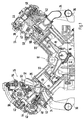
- FIG. 1 shows a sectional view of a V8 engine
- Fig. 2 is a schematic Representation of the two rows of cylinders of a V8 engine
- Figure 3 shows the firing order of a V8 engine with a partial representation of the charge exchange of three adjacent cylinders
- 4 is a schematic representation of a cylinder bank row
- Fig. 5 is a graphical Representation of valve lift curves and Fig. 6 with a different cam widths provided exhaust camshaft.
- the designed as a V8 engine internal combustion engine has one in a crankcase 10 arranged crankshaft 12.
- crankcase 10 At the offset with 90 ° KW arranged Crankshaft journals 14 are the Pleuelfworthe 16, of which only one visible is, screwed the connecting rod 18, which in turn via connecting rod 20 with the in the two cylinder bank rows arranged eight pistons 22 are connected.
- the two up Cylinder heads 24 fastened to the crankcase 10 take the for the 4-stroke combustion process on necessary and known components, wherein for all four arranged in a row cylinder find the same components use.
- Everyone Cylinder has two intake valves 26 and two exhaust valves 28, of which according to the sectional plane in Fig. 1 only one can be seen.
- the intake valves 26 monitor the leading to the combustion chamber 30 inlet channels 32, while the Exhaust valves 28 which also leading to the combustion chamber 30 exhaust ports 34th monitor.
- the four, flanged at each of the two rows of cylinder banks exhaust ports 34 are as 4-finger exhaust manifold formed after a short distance each in a open common exhaust pipe 36.
- the located on the suction side Inlet channels 32 are connected via an unillustrated intake system with combustion air provided.
- the actuation of the intake and exhaust valves 26, 28 takes place by means of a Intake camshaft 38 and exhaust camshaft 40.
- the intake and exhaust ports Exhaust camshaft 38, 40 each have four pairs of intake cams 42 and Exhaust cam 44, wherein the cylinder specific special training of the cam will be described later in more detail.
- valve springs 50, 52 is u.a. made sure that the Inlet and exhaust valves 26, 28 during the basic phase of the cams 46, 48 the Inlet or outlet channel 32, 34 securely close.
- injectors 54 Fuel is injected into the intake ports 32, which when opening the intake valve 26 with Help an ignition device designed as a spark plug 56 in the combustion chamber 30 to Combustion is brought.
- the firing order is distributed on the two rows of cylinder banks arranged cylinders 1 to 4 or 5 to 8 shown.
- the firing order based on the two rows of cylinder banks asymmetrical and has three different firing intervals per cylinder bank row.
- the ignition interval is 90 ° CA, between the cylinders 2 and 3 and 1 and 4 180 ° KW and between cylinders 2 and 4 270 ° KW.
- this is the Zündzeitticianabpartie in the second row of cylinders 5 to 8 between cylinder 5 and 6 90 ° KW, between cylinder 6 and 7 and between cylinder 5 and 8 180 ° KW and between cylinder 7 and 8 270 ° KW.
- the distance by 180 ° KW exhaust cylinders 1 and 3 or 1 and 4 within the cylinder row 1 - 4 and the Cylinders 6 and 7 or 5 and 8 within the row of cylinders 5 - 8 have the from Air effort ago disadvantaged cylinder 3, 4, 5, 7 a larger cam width for on the exhaust camshaft 40 arranged on cam 44.
- Fig. 5 is with the left solid curve A, the valve lift for the exhaust valves 28 of the cylinder 3, 4, 5th 7, while the smaller valve lift curve shown in dashed lines A 'is associated with the exhaust valves 28 of the cylinders 1, 2, 6, 8.
Landscapes
- Engineering & Computer Science (AREA)
- Mechanical Engineering (AREA)
- General Engineering & Computer Science (AREA)
- Valve-Gear Or Valve Arrangements (AREA)
- Valve Device For Special Equipments (AREA)
- Output Control And Ontrol Of Special Type Engine (AREA)
- Cylinder Crankcases Of Internal Combustion Engines (AREA)
- Exhaust Silencers (AREA)
Description
Claims (6)
- Mehrzylindrige Brennkraftmaschine mit mindestens einer Zylinderreihe, die ein Zylinderkopfgehäuse mit darin angeordneten Ein- und Auslaßventilen aufweist, die über Steuermittel in Abhängigkeit von der Drehlage der Kurbelwelle Verbrennungsluft den Zylindern zuführen und Verbrennungsabgase über eine Abgasanlage abführen, dadurch gekennzeichnet, das Mittel (44') zur Realisierung von unterschiedlichen Auslaß-Ventilhubverläufen von mindestens zwei in einer Zylinderreihe angeordneten Zylindern vorgesehen sind, die zu einer Reduzierung von Öffnungs-Überschneidungsphasen dieser Auslaßventile (28) führen, wobei sich das Einlaßventil (26) und das Auslaßventil (28) einer der beiden Zylinder selbst in einer Öffnungs-Überschneidungsphase befinden.
- Mehrzylindrige Brennkraftmaschine nach Anspruch 1, dadurch gekennzeichnet, daß die Einlaß-(26) und die Auslaßventile (28) über eine Nockenwelle (38, 40) und Nockenwellenfolger (44, 44') betätigt werden, wobei die auf der Auslaßnockenwelle (40) angeordneten Nocken (44, 44') unterschiedliche Nockenformen aufweisen.
- Mehrzylindrige Brennkraftmaschinen nach Anspruch 1 oder 2, dadurch gekennzeichnet, daß die auf der Auslaßnockenwelle (40) angeordneten Nocken (44, 44') unterschiedliche Nockenbreiten aufweisen.
- Mehrzylindrige Brennkraftmaschine nach Anspruch 3, dadurch gekennzeichnet, daß bei 1mm Ventilhub der/die schmalen Nocken (44') eine um 10° bis 20° kleinere Nockenbreite aufweisen, als der/die breiten Nocken (44).
- Mehrzylindrige Brennkraftmaschine nach einem der vorhergehenden Ansprüche, dadurch gekennzeichnet, daß die Brennkraftmaschine als mit zwei Zylinderreihen versehener V8-Motor ausgebildet ist, dessen Kurbelwelle eine 90° Kröpfung aufweist.
- Mehrzylindrige Brennkraftmaschine nach Anspruch 5, dadurch gekennzeichnet, daß auf der Abgasseite der beiden Zylinderreihen jeweils ein 4-Finger-Abgaskrümmer vorgesehen ist, der jeweils in ein gemeinsames Abgasrohr (36) einmündet.
Applications Claiming Priority (3)
| Application Number | Priority Date | Filing Date | Title |
|---|---|---|---|
| DE19954689A DE19954689A1 (de) | 1999-11-13 | 1999-11-13 | Mehrzylindrige Brennkraftmaschine |
| DE19954689 | 1999-11-13 | ||
| PCT/EP2000/010450 WO2001036793A1 (de) | 1999-11-13 | 2000-10-24 | Mehrzylindrige brennkraftmaschine |
Publications (2)
| Publication Number | Publication Date |
|---|---|
| EP1144810A1 EP1144810A1 (de) | 2001-10-17 |
| EP1144810B1 true EP1144810B1 (de) | 2005-01-12 |
Family
ID=7928958
Family Applications (1)
| Application Number | Title | Priority Date | Filing Date |
|---|---|---|---|
| EP00974441A Expired - Lifetime EP1144810B1 (de) | 1999-11-13 | 2000-10-24 | Mehrzylindrige brennkraftmaschine |
Country Status (9)
| Country | Link |
|---|---|
| US (1) | US6397802B1 (de) |
| EP (1) | EP1144810B1 (de) |
| JP (1) | JP5010082B2 (de) |
| KR (1) | KR100749232B1 (de) |
| CN (1) | CN1154788C (de) |
| AT (1) | ATE287027T1 (de) |
| DE (2) | DE19954689A1 (de) |
| ES (1) | ES2231280T3 (de) |
| WO (1) | WO2001036793A1 (de) |
Families Citing this family (23)
| Publication number | Priority date | Publication date | Assignee | Title |
|---|---|---|---|---|
| DE10046221A1 (de) * | 2000-09-19 | 2002-10-02 | Bayerische Motoren Werke Ag | Verfahren und Vorrichtung zur Steuerung der zylinderselektiven Füllung bei Verbrennungsmotoren mit variablem Ventiltrieb |
| DE102004012428A1 (de) * | 2003-09-23 | 2005-04-28 | Bosch Gmbh Robert | Verfahren, Computerprogramm und Vorrichtung zum Betreiben einer Brennkraftmaschine |
| SE531208C8 (de) * | 2004-03-31 | 2009-02-17 | ||
| JP4305355B2 (ja) | 2004-10-04 | 2009-07-29 | トヨタ自動車株式会社 | 多気筒内燃機関 |
| DE102005032791A1 (de) * | 2005-07-14 | 2007-01-18 | Deutz Ag | Abgasrückführung durch Zusatzöffnen der Einlassventile während der Auslasshuböffnung der Auslassventile |
| JP2007085218A (ja) * | 2005-09-21 | 2007-04-05 | Toyota Motor Corp | 内燃機関の制御装置 |
| JP4661511B2 (ja) | 2005-10-03 | 2011-03-30 | トヨタ自動車株式会社 | エンジン |
| US7275511B1 (en) * | 2006-07-26 | 2007-10-02 | Gm Global Technology Operations, Inc. | Intake manifold assembly |
| FR2910526A1 (fr) * | 2006-12-22 | 2008-06-27 | Renault Sas | Moteur a combustion interne adapte a ameliorer la vidange de ses cylindres. |
| DE102009053269A1 (de) * | 2009-11-13 | 2011-05-26 | Bayerische Motoren Werke Aktiengesellschaft | Brennkraftmaschine |
| US9316151B2 (en) * | 2011-02-18 | 2016-04-19 | GM Global Technology Operations LLC | Engine assembly including crankshaft for V8 arrangement |
| DE102011084834A1 (de) * | 2011-10-20 | 2013-04-25 | Ford Global Technologies, Llc | Brennkraftmaschine mit mehreren Auslaßöffnungen je Zylinder und Ladungswechselverfahren für eine derartige Brennkraftmaschine |
| KR101316857B1 (ko) * | 2011-12-15 | 2013-10-08 | 현대자동차주식회사 | 배기 밸브 제어 시스템 |
| GB2501311B (en) * | 2012-04-20 | 2014-08-13 | Ford Global Tech Llc | Camshaft for the exhaust side of a multiple-cylinder four-stroke internal combustion engine |
| DE102012210303B4 (de) * | 2012-06-19 | 2014-05-15 | Ford Global Technologies, Llc | Fremdgezündete Mehrzylinder-Brennkraftmaschine mit Teilabschaltung und Verfahren zum Betreiben einer derartigen Brennkraftmaschine |
| US9594226B2 (en) | 2013-10-18 | 2017-03-14 | Corning Optical Communications LLC | Optical fiber cable with reinforcement |
| JP2016217217A (ja) * | 2015-05-18 | 2016-12-22 | ヤマハ発動機株式会社 | V型8気筒エンジン及び船外機 |
| US10539051B2 (en) | 2015-11-06 | 2020-01-21 | Borgwarner Inc. | Valve operating system providing variable valve lift and/or variable valve timing |
| DE102017123136A1 (de) * | 2017-10-05 | 2019-04-11 | Man Truck & Bus Ag | Brennkraftmaschine mit Ventiltaschen |
| CN108150238B (zh) * | 2018-01-11 | 2019-11-05 | 东阳市天齐科技有限公司 | 凸凹轮转子双缸四冲程发动机 |
| DE102018122342A1 (de) * | 2018-09-13 | 2020-03-19 | Man Truck & Bus Se | Verfahren zum Betreiben einer Brennkraftmaschine |
| US11946827B2 (en) | 2021-06-11 | 2024-04-02 | Honda Motor Co., Ltd. | Valve testing apparatus |
| CN115977760B (zh) * | 2023-02-27 | 2025-05-30 | 中国第一汽车股份有限公司 | 一种变升程配气机构、发动机以及车辆 |
Family Cites Families (16)
| Publication number | Priority date | Publication date | Assignee | Title |
|---|---|---|---|---|
| US4068630A (en) * | 1975-12-12 | 1978-01-17 | General Motors Corporation | Engine with noise reducing exhaust valve arrangement |
| JPS5770914A (en) * | 1980-10-20 | 1982-05-01 | Yamaha Motor Co Ltd | Air intake controller for multi-valvetype internal combustionn engine |
| JPS5946310A (ja) * | 1982-09-10 | 1984-03-15 | Mazda Motor Corp | エンジンのバルブタイミング制御装置 |
| JPH0424085Y2 (de) * | 1985-03-04 | 1992-06-05 | ||
| JPH079187B2 (ja) * | 1985-06-07 | 1995-02-01 | ヤマハ発動機株式会社 | 並列4気筒エンジンの排気装置 |
| DE3523791A1 (de) * | 1985-07-03 | 1987-01-08 | Odilo Schwaiger | Ventilsteuerung fuer brennkraftmaschinen |
| JPS63192908A (ja) * | 1987-02-05 | 1988-08-10 | Mazda Motor Corp | エンジンの動弁装置 |
| JPH01159417A (ja) * | 1987-12-15 | 1989-06-22 | Nissan Motor Co Ltd | 内燃機関の弁装置 |
| EP0319956B1 (de) | 1987-12-08 | 1992-10-28 | Nissan Motor Co., Ltd. | Ventilsteuervorrichtung |
| JP2736997B2 (ja) * | 1989-04-27 | 1998-04-08 | 本田技研工業株式会社 | 内燃機関の弁駆動装置および弁駆動方法 |
| JPH039016A (ja) * | 1989-06-06 | 1991-01-16 | Mazda Motor Corp | 多気筒エンジンの排気構造 |
| JP2962894B2 (ja) * | 1991-09-30 | 1999-10-12 | マツダ株式会社 | 車両のパワートレイン構造 |
| JP3249163B2 (ja) * | 1992-01-10 | 2002-01-21 | マツダ株式会社 | タ−ボ過給機付きエンジンの吸気装置 |
| DE19606054C2 (de) * | 1996-02-19 | 1998-07-30 | Porsche Ag | Ventiltrieb einer Brennkraftmaschine |
| JP3834921B2 (ja) * | 1997-04-02 | 2006-10-18 | 三菱自動車工業株式会社 | 可変動弁機構 |
| DE19806054A1 (de) * | 1998-02-13 | 1999-08-19 | Lre Technology Partner Gmbh | Testkarte für eine optische oder amperometrische Bestimmung der Konzentration einer Substanz in einer Flüssigkeit |
-
1999
- 1999-11-13 DE DE19954689A patent/DE19954689A1/de not_active Ceased
-
2000
- 2000-10-24 CN CNB008027579A patent/CN1154788C/zh not_active Expired - Fee Related
- 2000-10-24 EP EP00974441A patent/EP1144810B1/de not_active Expired - Lifetime
- 2000-10-24 WO PCT/EP2000/010450 patent/WO2001036793A1/de not_active Ceased
- 2000-10-24 AT AT00974441T patent/ATE287027T1/de active
- 2000-10-24 ES ES00974441T patent/ES2231280T3/es not_active Expired - Lifetime
- 2000-10-24 KR KR1020017008800A patent/KR100749232B1/ko not_active Expired - Fee Related
- 2000-10-24 JP JP2001538652A patent/JP5010082B2/ja not_active Expired - Fee Related
- 2000-10-24 US US09/889,224 patent/US6397802B1/en not_active Expired - Lifetime
- 2000-10-24 DE DE50009217T patent/DE50009217D1/de not_active Expired - Lifetime
Also Published As
| Publication number | Publication date |
|---|---|
| ATE287027T1 (de) | 2005-01-15 |
| DE19954689A1 (de) | 2001-05-23 |
| JP5010082B2 (ja) | 2012-08-29 |
| CN1154788C (zh) | 2004-06-23 |
| KR100749232B1 (ko) | 2007-08-13 |
| JP2003515025A (ja) | 2003-04-22 |
| US6397802B1 (en) | 2002-06-04 |
| EP1144810A1 (de) | 2001-10-17 |
| DE50009217D1 (de) | 2005-02-17 |
| WO2001036793A1 (de) | 2001-05-25 |
| CN1336980A (zh) | 2002-02-20 |
| ES2231280T3 (es) | 2005-05-16 |
| KR20010102974A (ko) | 2001-11-17 |
Similar Documents
| Publication | Publication Date | Title |
|---|---|---|
| DE19954689A1 (de) | Mehrzylindrige Brennkraftmaschine | |
| DE19546549C5 (de) | Verfahren zum Ab- und Zuschalten einzelner Zylinder | |
| EP0663042B1 (de) | Hybridgesteuerter viertakt-ottomotor | |
| DE2951321C2 (de) | ||
| DE2827630A1 (de) | Mehrzylinder-brennkraftmaschine mit abgasrezirkulierung | |
| DE102011086622A1 (de) | Verfahren zum Abschalten und zum Aktivieren eines Zylinders einer Brennkraftmaschine | |
| DE102004046534B4 (de) | Verfahren und Vorrichtung zum Betreiben eines Motors | |
| WO2007003360A1 (de) | Variabler ventiltrieb einer kolben-brennkraftmaschine | |
| EP1352158B1 (de) | Verfahren und vorrichtung zum betreiben einer brennkraftmaschine | |
| DE3212910A1 (de) | Brennstoff-einlasssystem fuer einen motor mit vorverdichtung | |
| EP2499346B1 (de) | Brennkraftmaschine mit acht zylindern in v-bauart | |
| DE102011084834A1 (de) | Brennkraftmaschine mit mehreren Auslaßöffnungen je Zylinder und Ladungswechselverfahren für eine derartige Brennkraftmaschine | |
| DE69514148T2 (de) | Abgassystem für Motor | |
| DE3874101T2 (de) | Einlassvorrichtung fuer mehrzylinderbrennkraftmaschinen. | |
| EP1234968B1 (de) | Verfahren zum Synchronisieren der Füllung von Zylindern einer Brennkraftmaschine | |
| DE102013001424A1 (de) | Einlass- und Auslassvorrichtung eines Mehrzylindermotors, Verbrennungsmotor, Verfahren zum Steuern bzw. Regeln einer Luftladung dafür | |
| DE102004023590A1 (de) | Verfahren zum Betrieb eines Verbrennungsmotors sowie Verbrennungsmotor zur Ausführung des Verfahrens | |
| DE102013206898A1 (de) | Nockenwelle | |
| DE2943560C2 (de) | Vorrichtung für einen Verbrennungsmotor | |
| DE10151530A1 (de) | Abgasabführung für einen Hochleistungs-Mehrzylinder-Viertaktmotor | |
| EP0985085B1 (de) | Verfahren und vorrichtung zum betreiben einer brennkraftmaschine | |
| DE102005032791A1 (de) | Abgasrückführung durch Zusatzöffnen der Einlassventile während der Auslasshuböffnung der Auslassventile | |
| DE10357986B4 (de) | Variable Ventilsteuervorrichtung für einen Verbrennungsmotor | |
| EP3850205A1 (de) | Verfahren zum betreiben einer brennkraftmaschine | |
| DE102004027474B4 (de) | Viertakt-Verbrennungsmotor mit Abgasturbolader und Verfahren zur Optimierung seines Betriebs |
Legal Events
| Date | Code | Title | Description |
|---|---|---|---|
| PUAI | Public reference made under article 153(3) epc to a published international application that has entered the european phase |
Free format text: ORIGINAL CODE: 0009012 |
|
| AK | Designated contracting states |
Kind code of ref document: A1 Designated state(s): AT BE CH CY DE DK ES FI FR GB GR IE IT LI LU MC NL PT SE |
|
| 17P | Request for examination filed |
Effective date: 20011126 |
|
| GRAP | Despatch of communication of intention to grant a patent |
Free format text: ORIGINAL CODE: EPIDOSNIGR1 |
|
| GRAS | Grant fee paid |
Free format text: ORIGINAL CODE: EPIDOSNIGR3 |
|
| GRAA | (expected) grant |
Free format text: ORIGINAL CODE: 0009210 |
|
| AK | Designated contracting states |
Kind code of ref document: B1 Designated state(s): AT BE CH CY DE DK ES FI FR GB GR IE IT LI LU MC NL PT SE |
|
| PG25 | Lapsed in a contracting state [announced via postgrant information from national office to epo] |
Ref country code: FI Free format text: LAPSE BECAUSE OF FAILURE TO SUBMIT A TRANSLATION OF THE DESCRIPTION OR TO PAY THE FEE WITHIN THE PRESCRIBED TIME-LIMIT Effective date: 20050112 Ref country code: IE Free format text: LAPSE BECAUSE OF FAILURE TO SUBMIT A TRANSLATION OF THE DESCRIPTION OR TO PAY THE FEE WITHIN THE PRESCRIBED TIME-LIMIT Effective date: 20050112 Ref country code: NL Free format text: LAPSE BECAUSE OF FAILURE TO SUBMIT A TRANSLATION OF THE DESCRIPTION OR TO PAY THE FEE WITHIN THE PRESCRIBED TIME-LIMIT Effective date: 20050112 |
|
| REG | Reference to a national code |
Ref country code: GB Ref legal event code: FG4D Free format text: NOT ENGLISH |
|
| REG | Reference to a national code |
Ref country code: CH Ref legal event code: EP |
|
| REG | Reference to a national code |
Ref country code: SE Ref legal event code: TRGR |
|
| REF | Corresponds to: |
Ref document number: 50009217 Country of ref document: DE Date of ref document: 20050217 Kind code of ref document: P |
|
| REG | Reference to a national code |
Ref country code: IE Ref legal event code: FG4D Free format text: GERMAN |
|
| PG25 | Lapsed in a contracting state [announced via postgrant information from national office to epo] |
Ref country code: DK Free format text: LAPSE BECAUSE OF FAILURE TO SUBMIT A TRANSLATION OF THE DESCRIPTION OR TO PAY THE FEE WITHIN THE PRESCRIBED TIME-LIMIT Effective date: 20050412 |
|
| REG | Reference to a national code |
Ref country code: ES Ref legal event code: FG2A Ref document number: 2231280 Country of ref document: ES Kind code of ref document: T3 |
|
| GBT | Gb: translation of ep patent filed (gb section 77(6)(a)/1977) |
Effective date: 20050422 |
|
| NLV1 | Nl: lapsed or annulled due to failure to fulfill the requirements of art. 29p and 29m of the patents act | ||
| REG | Reference to a national code |
Ref country code: IE Ref legal event code: FD4D |
|
| PG25 | Lapsed in a contracting state [announced via postgrant information from national office to epo] |
Ref country code: CY Free format text: LAPSE BECAUSE OF FAILURE TO SUBMIT A TRANSLATION OF THE DESCRIPTION OR TO PAY THE FEE WITHIN THE PRESCRIBED TIME-LIMIT Effective date: 20051024 |
|
| PG25 | Lapsed in a contracting state [announced via postgrant information from national office to epo] |
Ref country code: LI Free format text: LAPSE BECAUSE OF NON-PAYMENT OF DUE FEES Effective date: 20051031 Ref country code: CH Free format text: LAPSE BECAUSE OF NON-PAYMENT OF DUE FEES Effective date: 20051031 Ref country code: LU Free format text: LAPSE BECAUSE OF NON-PAYMENT OF DUE FEES Effective date: 20051031 Ref country code: BE Free format text: LAPSE BECAUSE OF NON-PAYMENT OF DUE FEES Effective date: 20051031 Ref country code: MC Free format text: LAPSE BECAUSE OF NON-PAYMENT OF DUE FEES Effective date: 20051031 |
|
| ET | Fr: translation filed | ||
| PLBE | No opposition filed within time limit |
Free format text: ORIGINAL CODE: 0009261 |
|
| STAA | Information on the status of an ep patent application or granted ep patent |
Free format text: STATUS: NO OPPOSITION FILED WITHIN TIME LIMIT |
|
| 26N | No opposition filed |
Effective date: 20051013 |
|
| REG | Reference to a national code |
Ref country code: CH Ref legal event code: PL |
|
| BERE | Be: lapsed |
Owner name: DR.ING. H.C.F. PORSCHE A.G. Effective date: 20051031 |
|
| PG25 | Lapsed in a contracting state [announced via postgrant information from national office to epo] |
Ref country code: PT Free format text: LAPSE BECAUSE OF NON-PAYMENT OF DUE FEES Effective date: 20050612 |
|
| PG25 | Lapsed in a contracting state [announced via postgrant information from national office to epo] |
Ref country code: GR Free format text: LAPSE BECAUSE OF NON-PAYMENT OF DUE FEES Effective date: 20050112 |
|
| REG | Reference to a national code |
Ref country code: FR Ref legal event code: TP |
|
| REG | Reference to a national code |
Ref country code: FR Ref legal event code: CD |
|
| PGFP | Annual fee paid to national office [announced via postgrant information from national office to epo] |
Ref country code: ES Payment date: 20091023 Year of fee payment: 10 |
|
| REG | Reference to a national code |
Ref country code: FR Ref legal event code: TP |
|
| REG | Reference to a national code |
Ref country code: GB Ref legal event code: 732E Free format text: REGISTERED BETWEEN 20110310 AND 20110316 |
|
| REG | Reference to a national code |
Ref country code: GB Ref legal event code: 732E Free format text: REGISTERED BETWEEN 20110331 AND 20110406 |
|
| REG | Reference to a national code |
Ref country code: ES Ref legal event code: FD2A Effective date: 20111121 |
|
| PG25 | Lapsed in a contracting state [announced via postgrant information from national office to epo] |
Ref country code: ES Free format text: LAPSE BECAUSE OF NON-PAYMENT OF DUE FEES Effective date: 20101025 |
|
| REG | Reference to a national code |
Ref country code: FR Ref legal event code: PLFP Year of fee payment: 16 |
|
| REG | Reference to a national code |
Ref country code: FR Ref legal event code: PLFP Year of fee payment: 17 |
|
| PGFP | Annual fee paid to national office [announced via postgrant information from national office to epo] |
Ref country code: FR Payment date: 20161020 Year of fee payment: 17 Ref country code: GB Payment date: 20161020 Year of fee payment: 17 |
|
| PGFP | Annual fee paid to national office [announced via postgrant information from national office to epo] |
Ref country code: SE Payment date: 20161019 Year of fee payment: 17 Ref country code: AT Payment date: 20161020 Year of fee payment: 17 Ref country code: IT Payment date: 20161024 Year of fee payment: 17 |
|
| REG | Reference to a national code |
Ref country code: SE Ref legal event code: EUG |
|
| REG | Reference to a national code |
Ref country code: AT Ref legal event code: MM01 Ref document number: 287027 Country of ref document: AT Kind code of ref document: T Effective date: 20171024 |
|
| GBPC | Gb: european patent ceased through non-payment of renewal fee |
Effective date: 20171024 |
|
| REG | Reference to a national code |
Ref country code: FR Ref legal event code: ST Effective date: 20180629 |
|
| PG25 | Lapsed in a contracting state [announced via postgrant information from national office to epo] |
Ref country code: GB Free format text: LAPSE BECAUSE OF NON-PAYMENT OF DUE FEES Effective date: 20171024 |
|
| PG25 | Lapsed in a contracting state [announced via postgrant information from national office to epo] |
Ref country code: SE Free format text: LAPSE BECAUSE OF NON-PAYMENT OF DUE FEES Effective date: 20171025 Ref country code: AT Free format text: LAPSE BECAUSE OF NON-PAYMENT OF DUE FEES Effective date: 20171024 Ref country code: FR Free format text: LAPSE BECAUSE OF NON-PAYMENT OF DUE FEES Effective date: 20171031 |
|
| PG25 | Lapsed in a contracting state [announced via postgrant information from national office to epo] |
Ref country code: IT Free format text: LAPSE BECAUSE OF NON-PAYMENT OF DUE FEES Effective date: 20171024 |
|
| PGFP | Annual fee paid to national office [announced via postgrant information from national office to epo] |
Ref country code: DE Payment date: 20190923 Year of fee payment: 20 |
|
| REG | Reference to a national code |
Ref country code: DE Ref legal event code: R071 Ref document number: 50009217 Country of ref document: DE |