EP1141936B1 - Gesteuerter akustischer wellenleiter zur schalldämpfung - Google Patents
Gesteuerter akustischer wellenleiter zur schalldämpfung Download PDFInfo
- Publication number
- EP1141936B1 EP1141936B1 EP99963544A EP99963544A EP1141936B1 EP 1141936 B1 EP1141936 B1 EP 1141936B1 EP 99963544 A EP99963544 A EP 99963544A EP 99963544 A EP99963544 A EP 99963544A EP 1141936 B1 EP1141936 B1 EP 1141936B1
- Authority
- EP
- European Patent Office
- Prior art keywords
- waveguide according
- hollow cavity
- duct
- controlled
- sound
- Prior art date
- Legal status (The legal status is an assumption and is not a legal conclusion. Google has not performed a legal analysis and makes no representation as to the accuracy of the status listed.)
- Expired - Lifetime
Links
Images




Classifications
-
- G—PHYSICS
- G10—MUSICAL INSTRUMENTS; ACOUSTICS
- G10K—SOUND-PRODUCING DEVICES; METHODS OR DEVICES FOR PROTECTING AGAINST, OR FOR DAMPING, NOISE OR OTHER ACOUSTIC WAVES IN GENERAL; ACOUSTICS NOT OTHERWISE PROVIDED FOR
- G10K11/00—Methods or devices for transmitting, conducting or directing sound in general; Methods or devices for protecting against, or for damping, noise or other acoustic waves in general
- G10K11/16—Methods or devices for protecting against, or for damping, noise or other acoustic waves in general
- G10K11/172—Methods or devices for protecting against, or for damping, noise or other acoustic waves in general using resonance effects
-
- F—MECHANICAL ENGINEERING; LIGHTING; HEATING; WEAPONS; BLASTING
- F01—MACHINES OR ENGINES IN GENERAL; ENGINE PLANTS IN GENERAL; STEAM ENGINES
- F01N—GAS-FLOW SILENCERS OR EXHAUST APPARATUS FOR MACHINES OR ENGINES IN GENERAL; GAS-FLOW SILENCERS OR EXHAUST APPARATUS FOR INTERNAL-COMBUSTION ENGINES
- F01N1/00—Silencing apparatus characterised by method of silencing
- F01N1/02—Silencing apparatus characterised by method of silencing by using resonance
-
- F—MECHANICAL ENGINEERING; LIGHTING; HEATING; WEAPONS; BLASTING
- F01—MACHINES OR ENGINES IN GENERAL; ENGINE PLANTS IN GENERAL; STEAM ENGINES
- F01N—GAS-FLOW SILENCERS OR EXHAUST APPARATUS FOR MACHINES OR ENGINES IN GENERAL; GAS-FLOW SILENCERS OR EXHAUST APPARATUS FOR INTERNAL-COMBUSTION ENGINES
- F01N1/00—Silencing apparatus characterised by method of silencing
- F01N1/06—Silencing apparatus characterised by method of silencing by using interference effect
- F01N1/065—Silencing apparatus characterised by method of silencing by using interference effect by using an active noise source, e.g. speakers
-
- F—MECHANICAL ENGINEERING; LIGHTING; HEATING; WEAPONS; BLASTING
- F01—MACHINES OR ENGINES IN GENERAL; ENGINE PLANTS IN GENERAL; STEAM ENGINES
- F01N—GAS-FLOW SILENCERS OR EXHAUST APPARATUS FOR MACHINES OR ENGINES IN GENERAL; GAS-FLOW SILENCERS OR EXHAUST APPARATUS FOR INTERNAL-COMBUSTION ENGINES
- F01N1/00—Silencing apparatus characterised by method of silencing
- F01N1/16—Silencing apparatus characterised by method of silencing by using movable parts
- F01N1/22—Silencing apparatus characterised by method of silencing by using movable parts the parts being resilient walls
-
- F—MECHANICAL ENGINEERING; LIGHTING; HEATING; WEAPONS; BLASTING
- F01—MACHINES OR ENGINES IN GENERAL; ENGINE PLANTS IN GENERAL; STEAM ENGINES
- F01N—GAS-FLOW SILENCERS OR EXHAUST APPARATUS FOR MACHINES OR ENGINES IN GENERAL; GAS-FLOW SILENCERS OR EXHAUST APPARATUS FOR INTERNAL-COMBUSTION ENGINES
- F01N2490/00—Structure, disposition or shape of gas-chambers
- F01N2490/14—Dead or resonance chambers connected to gas flow tube by relatively short side-tubes
Definitions
- the invention relates to a controlled acoustic waveguide for sound attenuation in the manner of an elongated hollow chamber, which has an opening at its first Front is connected to a sound-conducting channel and its Longitudinal resonances can be tuned to a sound spectrum to be damped by by means of a microphone that is at least one immediately in front of the membrane Speaker is located on the second end face of the hollow chamber, the Membrane vibrations are detected and the microphone signal with an amplifier inverted and depending on a characterizing the sound in the channel Signal from a sensor is fed back to the loudspeaker.
- Silencers are known for damping low-frequency noise in ducts which the longitudinal resonances of elongated hollow chambers, so-called acoustic Waveguides are used, e.g. B. according to DE 19612572, or Lamancusa, J.S .: An actively tuned passive muffler system for engine silencing. Proceedings Noise-Con 87, 1987, pp. 313-318.
- These waveguides are connected to the front through an opening sound-conducting channel and are either perpendicular to the channel or nestle in parallel to them.
- the first Longitudinal resonance in which the chamber length is a quarter of the wavelength of the Corresponds to resonance frequency, narrowband high attenuation is achieved.
- the sound pressure signal thus detected is used for filtering, amplification and further analysis steps as a control variable for at least one speaker in the Waveguide or cavity.
- the speaker emits a signal that itself, again after its modification by the resonator, with the sound at the location of the microphone in the channel or room superimposed in phase and thereby one Soundproofing causes.
- these actively influenced resonators on the one hand generates high sound pressures at low frequencies and thus also dampens them and on the other hand at least the loudspeaker is in front of possible e.g. thermal Protected loads in the channel. Disadvantages of these methods are specified dimensioning of the resonators, regardless of possible Changes in the original sound spectrum in the channel, as well as in the lack of protection of the microphone.
- DE 4027511 Subsystem used which preferably consists of passive absorber layers and protective cover layers.
- This procedure requires that a signal former proposed in DE 4027511 first of all, the behavior of everyone electroacoustic components (microphone, loudspeaker, box, etc.) and compensated secondly, impresses the desired termination impedance on the system. It was the Component properties thoroughly examined and described. After that are to implement this procedure inevitably complex and in practice only approximately realizable transfer functions of the signal former to implement.
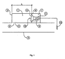
- the starting point of the controlled waveguide according to the invention according to FIG. 1 consists of an elongated hollow chamber (1) with pronounced longitudinal resonances, via an opening (2) on the first end face (3) with a sound-conducting channel (4) or room is acoustically connected.
- the length L of the hollow chamber (1) depends according to the sound spectrum occurring in channel (4), in which the frequencies with the fluctuating maximum sound amplitude due to operational conditions in a certain area, e.g. as a result of a changing gas temperature in the channel (4).
- the length L corresponds in this case about a quarter of the wavelength of the upper cutoff frequency Area.
- the membrane (8) of at least one loudspeaker (9) On the second end face (6) of the hollow chamber (1) is located in front of one further cavity (7) the membrane (8) of at least one loudspeaker (9), wherein the cavity (7) as an air spring and the membrane (8) as a flat mass Form resonance system.
- a microphone (10) is located in front of the membrane (8) Detection of membrane vibrations positioned. The microphone signal is on Input of an inverting amplifier (11) with adjustable gain on, whose output signal is used to control the loudspeaker (9).
- the acoustically reached as a result of the increased gain effective extension of the hollow chamber (1) means a displacement of its first Longitudinal resonance at lower frequencies, advantageously up to the lower limit of the Frequency range of the sound spectrum occurring in channel (4).
- the setting the gain is based on the control signal of at least one additional one Sensor (12), one for the frequencies with the highest sound amplitude in the channel delivers characteristic size to the amplifier (11).
- temperature sensors in the channel (4) and speed sensors are on as sensors (12) Fans, generators or motors and measuring elements for the gas flow from To name burners and exhaust systems.
- the sensor (12) without special protection, such as e.g. for microphones in an exhaust system would be required.
- An exemplary, particularly simple design of the sensor (12) represents a temperature-dependent resistance, which detects the temperature in the channel (4) and at the same time part of the feedback branch of a known one is inverting amplifier (11) and thereby controls its overall gain. Further advantageous configurations relate to the use of voltage and current-controlled amplifier (11) and expand the selection of possible sensors (12).
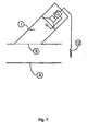
- the hollow chamber (1) can be straight or curved Have shape, protrude obliquely or perpendicularly from the channel or in the longitudinal direction abut the channel (4).
- one is Thermal insulation layer (13) between the hollow chamber (1) and channel (4) is provided. In to expected heating of the hollow chamber (1) improve those shown in Fig.
- FIG. 4 An exemplary embodiment of the controlled waveguide according to the invention is shown in Fig. 4 shown. Together with a conventional passive damper (18) of the opposite duct wall achieved attenuation values in FIG. 5 represent the two limit cases in the frequency domain depending on the set gain (11). The low temperature influence on the damping of the 4 underlines the controlled waveguide according to the invention Comparison of the measured attenuation at 20'C and 150'C in the channel in Fig. 6.
Landscapes
- Engineering & Computer Science (AREA)
- Chemical & Material Sciences (AREA)
- Combustion & Propulsion (AREA)
- Mechanical Engineering (AREA)
- General Engineering & Computer Science (AREA)
- Physics & Mathematics (AREA)
- Acoustics & Sound (AREA)
- Multimedia (AREA)
- Soundproofing, Sound Blocking, And Sound Damping (AREA)
- Exhaust Silencers (AREA)
- Pipe Accessories (AREA)
- Electrophonic Musical Instruments (AREA)
Description
- Im Vergleich mit bekannten akustischen Wellenleitem erreicht der erfindungsgemäße gesteuerte Wellenleiter mit geringerem Bauvolumen (Hohlkammern bis ca. viermal kürzer) eine hohe Schalldämpfung bei tiefen Frequenzen.
- Der Frequenzbereich mit hoher Schalldämpfung des erfindungsgemäßen gesteuerten Wellenleiters ist aufgrund der Adaptivität an veränderliche Schallspektren auf ca. 2 Oktaven erweitert.
- Der erfindungsgemäße gesteuerte Wellenleiter zeichnet sich durch eine einfache Konstruktion und insbesondere durch eine preiswerte analoge Verstärkung und Steuerung ohne aufwendige elektronische Filter oder digitale Signalanalyse aus.
- Weiterhin sind alle elektroakustischen Komponenten in der Hohlkammer des erfindungsgemäßen gesteuerten Wellenleiters nachhaltig vor Einflüssen durch Strömung, Staub und aggressive Medien im Kanal geschützt.
- Dieser Schutz erstreckt sich ebenfalls auf hohe Temperaturen z.B. in Abgassystemen, da beim erfindungsgemäßen gesteuerten Wellenleiter mehrere Möglichkeiten für eine effektive thermische Entkopplung vom Kanal gegeben sind.
- Fig. 1:
- Aufbau des erfindungsgemäßen gesteuerten Wellenleiters
- Fig. 2:
- Vorteilhafte Ausgestaltungen des erfindungsgemäßen gesteuerten Wellenleiters mit einer Wärmedämmschicht (13) zwischen Hohlkammer (1) und Kanal (4), mit Kühlkörpern (14) als Teil der Hohlkammerwand, mit einer erzwungenen Kühlung (15) nach Art eines Wärmetauschers sowie mit einer absorbierenden inneren Wandauskleidung (17)
- Fig.3:
- Vorteilhafte Ausgestaltungen des erfindungsgemäßen gesteuerten Wellenleiters mit einer Unterteilung der Hohlkammer (1) in mehrere unterschiedlich lange Röhren (16)
- Fig. 4:
- Beispielhafte Ausführung des erfindungsgemäßen gesteuerten Wellenleiters mit einem konventionellen passiven Dämpfer (18) an der gegenüberliegenden Kanalwand (Abmessungen in mm)
- Fig. 5:
- Gemessene Einfügungsdämpfung des beispielhaften gesteuerten Wellenleiters nach Fig. 4 ohne und mit Verstärkung
- Fig. 6:
- Gemessene Einfügungsdämpfung des beispielhaften gesteuerten Wellenleiters nach Fig. 4 mit Verstärkung bei 20'C und 150'C Lufttemperatur im Kanal (4)
- Fig. 7:
- Beispielhafter gesteuerter Wellenleiter mit schräg vom Kanal (4) abstehender Hohlkammer (1)
- Fig. 8:
- Beispielhafter gesteuerter Wellenleiter mit einer an einem gekrümmten Kanal (4) anliegenden Hohlkammer (1)
- Fig. 9:
- Beispielhafte Anordnung mehrerer gesteuerter Wellenleiter an mehreren Seitenwänden eines Kanals (4)
- Fig. 10:
- Beispielhafter gesteuerter Wellenleiter mit aerodynamisch günstiger Gestaltung und Positionierung nach Art einer Mittelkulisse innerhalb eines großen Kanals (4)
Claims (13)
- Gesteuerter akustischer Wellenleiter nach Art einer langgestreckten Hohlkammer (1), der über eine Öffnung (2) an seiner ersten Stirnseite (3) mit einem schallführenden Kanal (4) verbunden ist, wobei die Längsresonanzen der Hohlkammer (1) auf ein zu dämpfendes Schallspektrum abstimmbar sind, indem mittels eines Mikrofons (10), das sich unmittelbar vor der Membran (8) mindestens eines Lautsprechers (9) an der zweiten Stirnseite (6) der Hohlkammer (1) befindet, die Membranschwingungen erfaßt werden dadurch gekennzeichnet, dass das Mikrofonsignal mit einem Verstärker (11) invertiert und in Abhängigkeit von einem das Schallspektrum im Kanal (4) charakterisierenden Signal eines Sensors (12) verstärkt an den Lautsprecher (9) rückgekoppelt wird.
- Gesteuerter Wellenleiter nach Anspruch 1, dadurch gekennzeichnet, daß die Öffnung (2) mit einer schalldurchlässigen Schutzabdeckung (5) aus Lochblech, Vlies oder Folien versehen ist.
- Gesteuerter Wellenleiter nach Anspruch 1 und 2, dadurch gekennzeichnet, daß die Hohlkammer (1) senkrecht oder schräg vom Kanal (4) absteht oder an der geraden oder gekrümmten Kanalwand anliegt.
- Gesteuerter Wellenleiter nach Anspruch 1-3, dadurch gekennzeichnet, daß sich bei an der Wand des Kanals (4) anliegender Hohlkammer (1) eine Wärmedämmschicht (13) zwischen Kanal- und Hohlkammerwand befindet.
- Gesteuerter Wellenleiter nach Anspruch 1-4, dadurch gekennzeichnet, daß die Wände der Hohlkammer (1) teil- oder vollflächig mit Kühlkörpern (11) ausgestattet sind.
- Gesteuerter Wellenleiter nach Anspruch 1-5, dadurch gekennzeichnet, daß sich in der Hohlkammer (1) eine erzwungene Kühlung (15) nach Art von Wärmetauschern oder Peltier-Elementen befindet.
- Gesteuerter Wellenleiter nach Anspruch 1-6, dadurch gekennzeichnet, daß die Hohlkammer (1) durch eine Querunterteilung (16) in unterschiedliche lange Röhren geteilt ist.
- Gesteuerter Wellenleiter nach Anspruch 1-7, dadurch gekennzeichnet, daß die Wände der Hohlkammer (1) teil- oder vollflächig mit einer schallabsorbierenden Verkleidung (17) ausgestattet sind.
- Gesteuerter Wellenleiter nach Anspruch 1-8, dadurch gekennzeichnet, daß als Sensor (12) für das im Kanal (4) auftretende Schallspektrum Temperaturfühler, Drehzahlgeber sowie Meßglieder für den Gasfluß von Brennern und Abgassystemen verwendet werden.
- Gesteuerte Wellenleiter nach Anspruch 1-9, dadurch gekennzeichnet, daß mehrere gesteuerte Wellenleiter an mehreren Seitenwänden von Kanälen (4) mit rechteckigem Querschnitt verwendet werden.
- Gesteuerter Wellenleiter nach Anspruch 1-9, dadurch gekennzeichnet, daß eine ringförmige Hohlkammer (1) umlaufend um einen zylindrischen Kanal (4) verwendet wird.
- Gesteuerter Wellenleiter nach Anspruch 1,2 und 6-9, dadurch gekennzeichnet, daß der gesteuerte Wellenleiter aerodynamisch günstig gestaltet und nach Art einer Mittelkulisse innerhalb eines großen rechteckigen oder zylindrischen Kanals (4) positioniert ist.
- Gesteuerter Wellenleiter nach Anspruch 1 und 3-9, dadurch gekennzeichnet, daß statt der schalldurchlässigen Öffnung (2) eine akustisch wirksame Membran oder Platte die Verbindung zum Kanal (4) bildet.
Applications Claiming Priority (3)
| Application Number | Priority Date | Filing Date | Title |
|---|---|---|---|
| DE19861018 | 1998-12-15 | ||
| DE19861018A DE19861018C2 (de) | 1998-12-15 | 1998-12-15 | Gesteuerter akustischer Wellenleiter zur Schalldämpfung |
| PCT/EP1999/009966 WO2000036589A1 (de) | 1998-12-15 | 1999-12-15 | Gesteuerter akustischer wellenleiter zur schalldämpfung |
Publications (2)
| Publication Number | Publication Date |
|---|---|
| EP1141936A1 EP1141936A1 (de) | 2001-10-10 |
| EP1141936B1 true EP1141936B1 (de) | 2004-03-03 |
Family
ID=7893262
Family Applications (1)
| Application Number | Title | Priority Date | Filing Date |
|---|---|---|---|
| EP99963544A Expired - Lifetime EP1141936B1 (de) | 1998-12-15 | 1999-12-15 | Gesteuerter akustischer wellenleiter zur schalldämpfung |
Country Status (6)
| Country | Link |
|---|---|
| US (1) | US6963647B1 (de) |
| EP (1) | EP1141936B1 (de) |
| JP (1) | JP2002532999A (de) |
| AT (1) | ATE261170T1 (de) |
| DE (2) | DE19861018C2 (de) |
| WO (1) | WO2000036589A1 (de) |
Cited By (2)
| Publication number | Priority date | Publication date | Assignee | Title |
|---|---|---|---|---|
| DE102005001807A1 (de) * | 2005-01-13 | 2006-07-20 | Air Liquide Deutschland Gmbh | Verfahren zum Erhitzen eines Industrieofens und dafür geeignete Vorrichtung |
| DE102005048905B3 (de) * | 2005-10-10 | 2006-08-31 | Fraunhofer-Gesellschaft zur Förderung der angewandten Forschung e.V. | Aktiver Kanalschalldämpfer |
Families Citing this family (33)
| Publication number | Priority date | Publication date | Assignee | Title |
|---|---|---|---|---|
| US6771787B1 (en) * | 1998-09-03 | 2004-08-03 | Bose Corporation | Waveguide electroacoustical transducing |
| DE10201494A1 (de) * | 2002-01-17 | 2003-07-31 | Mann & Hummel Filter | Resonator |
| GB2387522B (en) * | 2002-04-10 | 2005-09-28 | Hobelsberger Max | Tunable active sound absorbers |
| DE102004040421A1 (de) * | 2004-08-19 | 2006-03-09 | J. Eberspächer GmbH & Co. KG | Aktiver Abgasschalldämpfer |
| DE102005011747B3 (de) * | 2005-03-11 | 2006-06-29 | Benteler Automobiltechnik Gmbh | Aktiver Abgasschalldämpfer |
| US7686132B2 (en) * | 2005-12-29 | 2010-03-30 | 3M Innovative Properties Company | Porous membrane |
| DE102006010558A1 (de) * | 2006-03-06 | 2007-09-13 | J. Eberspächer GmbH & Co. KG | Aktiver Schalldämpfer für eine Abgasanlage |
| DE102006042224B3 (de) * | 2006-09-06 | 2008-01-17 | J. Eberspächer GmbH & Co. KG | Aktiver Schalldämpfer für eine Abgasanlage |
| KR100811862B1 (ko) * | 2006-12-28 | 2008-03-10 | 한국표준과학연구원 | 압전배열막을 이용한 음향센서 |
| DE102007032600A1 (de) | 2007-07-11 | 2009-01-15 | Deutsches Zentrum für Luft- und Raumfahrt e.V. | Vorrichtung und Verfahren zur Verbesserung der Dämpfung von akustischen Wellen |
| EP2072769B1 (de) * | 2007-12-21 | 2010-06-16 | Robert Bosch Gmbh | Vorrichtung und Verfahren zur aktiven Lärmbekämpfung im Abgaskanal eines Verbrennungsmotors |
| US7753165B2 (en) | 2007-12-21 | 2010-07-13 | Robert Bosch Gmbh | Device and method for active noise cancellation in exhaust gas channel of a combustion engine |
| US8295526B2 (en) * | 2008-02-21 | 2012-10-23 | Bose Corporation | Low frequency enclosure for video display devices |
| US8351629B2 (en) * | 2008-02-21 | 2013-01-08 | Robert Preston Parker | Waveguide electroacoustical transducing |
| US8351630B2 (en) | 2008-05-02 | 2013-01-08 | Bose Corporation | Passive directional acoustical radiating |
| US9275628B2 (en) * | 2008-05-05 | 2016-03-01 | Bonnie S. Schnitta | Tunable frequency acoustic structures |
| US20100002385A1 (en) * | 2008-07-03 | 2010-01-07 | Geoff Lyon | Electronic device having active noise control and a port ending with curved lips |
| US8165311B2 (en) * | 2009-04-06 | 2012-04-24 | International Business Machines Corporation | Airflow optimization and noise reduction in computer systems |
| DE102009031848A1 (de) * | 2009-07-03 | 2011-01-05 | J. Eberspächer GmbH & Co. KG | Abgasanlage mit aktivem Schalldämpfer |
| US8265310B2 (en) * | 2010-03-03 | 2012-09-11 | Bose Corporation | Multi-element directional acoustic arrays |
| US8553894B2 (en) | 2010-08-12 | 2013-10-08 | Bose Corporation | Active and passive directional acoustic radiating |
| DE102012106515B4 (de) | 2012-07-18 | 2023-10-26 | Dr. Ing. H.C. F. Porsche Aktiengesellschaft | Verfahren und Vorrichtung zur Geräuscherzeugung im Innenraum eines Kraftfahrzeugs |
| FR3005993B1 (fr) * | 2013-05-23 | 2015-06-26 | Dcns | Systeme de silencieux actif pour ligne d'echappement d'un moteur diesel notamment de plateforme navale |
| DE102013210709A1 (de) * | 2013-06-07 | 2014-12-11 | Fraunhofer-Gesellschaft zur Förderung der angewandten Forschung e.V. | Schallstrahler-Anordnung für aktive Schalldämpfer |
| US9537527B2 (en) * | 2014-12-29 | 2017-01-03 | Samsung Electronics Co., Ltd. | User terminal apparatus |
| WO2016108439A1 (en) | 2014-12-29 | 2016-07-07 | Samsung Electronics Co., Ltd. | Foldable device and method of controlling the same |
| US10057701B2 (en) | 2015-03-31 | 2018-08-21 | Bose Corporation | Method of manufacturing a loudspeaker |
| US9451355B1 (en) | 2015-03-31 | 2016-09-20 | Bose Corporation | Directional acoustic device |
| FR3043177B1 (fr) | 2015-11-02 | 2019-08-23 | Technofirst | Installation pour la ventilation naturelle d'un local |
| FR3043179A1 (fr) | 2015-11-02 | 2017-05-05 | Technofirst | Installation pour la ventilation naturelle d'un local presentant un passage de ventilation associe a un amortisseur de bruit |
| FR3043178B1 (fr) | 2015-11-02 | 2019-08-23 | Technofirst | Installation pour la ventilation naturelle d'un local pourvue d'un amortisseur de bruit |
| DE102017203181B4 (de) | 2017-02-28 | 2021-08-26 | Audi Ag | Klangerzeugungsvorrichtung zur Erzeugung von Abgasanlagensound sowie ein zugehöriges Kraftfahrzeug |
| CN115331651B (zh) * | 2022-08-09 | 2023-03-31 | 四川大学 | 一种低频减振吸声一体化的声子晶体复合降噪结构及设计方法 |
Family Cites Families (16)
| Publication number | Priority date | Publication date | Assignee | Title |
|---|---|---|---|---|
| ZA825676B (en) | 1981-08-11 | 1983-06-29 | Sound Attenuators Ltd | Method and apparatus for low frequency active attennuation |
| US5457749A (en) * | 1990-04-09 | 1995-10-10 | Noise Cancellation Technologies, Inc. | Electronic muffler |
| US5229556A (en) * | 1990-04-25 | 1993-07-20 | Ford Motor Company | Internal ported band pass enclosure for sound cancellation |
| US5233137A (en) | 1990-04-25 | 1993-08-03 | Ford Motor Company | Protective anc loudspeaker membrane |
| DE4027511C1 (de) | 1990-08-30 | 1991-10-02 | Fraunhofer-Gesellschaft Zur Foerderung Der Angewandten Forschung E.V., 8000 Muenchen, De | |
| DE4033269A1 (de) * | 1990-10-19 | 1992-04-23 | Gillet Heinrich Gmbh | Schalldaempferanlage fuer kraftfahrzeuge |
| GB2253076B (en) * | 1991-02-21 | 1994-08-03 | Lotus Car | Method and apparatus for attenuating acoustic vibrations in a medium |
| US5619020A (en) * | 1991-08-29 | 1997-04-08 | Noise Cancellation Technologies, Inc. | Muffler |
| US5550334A (en) * | 1991-10-30 | 1996-08-27 | Noise Cancellation Technologies, Inc. | Actively sound reduced muffler having a venturi effect configuration |
| DE4226885C2 (de) | 1992-08-13 | 2001-04-19 | Bayerische Motoren Werke Ag | Schallabsorptionsverfahren für Kraftfahrzeuge |
| JP2587683Y2 (ja) * | 1993-08-12 | 1998-12-24 | カルソニック株式会社 | 能動型消音器 |
| DE4446080B4 (de) | 1994-12-22 | 2004-03-18 | Bayerische Motoren Werke Ag | Schallabsorptionssystem für Kraftfahrzeuge |
| FR2740599B1 (fr) * | 1995-10-30 | 1997-12-19 | Technofirst | Dispositif d'attenuation acoustique active destine a etre dispose a l'interieur d'un conduit, en particulier pour l'insonorisation de reseau de ventilation et/ou de climatisation |
| DE19612572A1 (de) | 1996-03-29 | 1997-10-02 | Fraunhofer Ges Forschung | Reinigbarer Schalldämpfer für tiefe Frequenzen |
| WO1997043754A1 (de) | 1996-05-14 | 1997-11-20 | Fraunhofer-Gesellschaft zur Förderung der angewandten Forschung e.V. | Reaktiver schalldämpfer |
| US6418227B1 (en) * | 1996-12-17 | 2002-07-09 | Texas Instruments Incorporated | Active noise control system and method for on-line feedback path modeling |
-
1998
- 1998-12-15 DE DE19861018A patent/DE19861018C2/de not_active Expired - Fee Related
-
1999
- 1999-12-15 WO PCT/EP1999/009966 patent/WO2000036589A1/de not_active Ceased
- 1999-12-15 EP EP99963544A patent/EP1141936B1/de not_active Expired - Lifetime
- 1999-12-15 DE DE59908778T patent/DE59908778D1/de not_active Expired - Lifetime
- 1999-12-15 AT AT99963544T patent/ATE261170T1/de active
- 1999-12-15 US US09/868,251 patent/US6963647B1/en not_active Expired - Fee Related
- 1999-12-15 JP JP2000588756A patent/JP2002532999A/ja active Pending
Cited By (2)
| Publication number | Priority date | Publication date | Assignee | Title |
|---|---|---|---|---|
| DE102005001807A1 (de) * | 2005-01-13 | 2006-07-20 | Air Liquide Deutschland Gmbh | Verfahren zum Erhitzen eines Industrieofens und dafür geeignete Vorrichtung |
| DE102005048905B3 (de) * | 2005-10-10 | 2006-08-31 | Fraunhofer-Gesellschaft zur Förderung der angewandten Forschung e.V. | Aktiver Kanalschalldämpfer |
Also Published As
| Publication number | Publication date |
|---|---|
| ATE261170T1 (de) | 2004-03-15 |
| DE59908778D1 (de) | 2004-04-08 |
| DE19861018C2 (de) | 2001-06-13 |
| US6963647B1 (en) | 2005-11-08 |
| DE19861018A1 (de) | 2000-06-29 |
| WO2000036589A1 (de) | 2000-06-22 |
| EP1141936A1 (de) | 2001-10-10 |
| JP2002532999A (ja) | 2002-10-02 |
Similar Documents
| Publication | Publication Date | Title |
|---|---|---|
| DE19861018C2 (de) | Gesteuerter akustischer Wellenleiter zur Schalldämpfung | |
| EP0481450B1 (de) | Schalldämpferanlage für Verbrennungsmotoren | |
| DE69330567T2 (de) | Gerät für rauschkompensation für ein kraftfahrzeug | |
| EP1862663B1 (de) | Integrierter Luftmassenmesser und Breitbanddämpfer | |
| EP0916817B1 (de) | Aktiver Schalldämpfer | |
| US20230304425A1 (en) | Drone elimination muffler | |
| DE4107878A1 (de) | Kuehlgeraet mit schalldaempfungsfunktion | |
| Mahesh et al. | Investigation on the acoustic performance of multiple Helmholtz resonator configurations | |
| EP0898774B1 (de) | Reaktiver schalldämpfer | |
| EP1329876A2 (de) | Resonator zur Schalldämpfung in einem schallführenden Rohrkanal | |
| DE19526098C1 (de) | Verfahren zur Maximierung der Dämpfungswirkung einer Vorrichtung zur aktiven Geräuschdämpfung | |
| DE69128352T2 (de) | Schalldämpfervorrichtung | |
| DE69329302T2 (de) | Lärmkontrollegerät | |
| Boden et al. | A study of high level tonal and broadband random excitation for acoustic liners | |
| Villau et al. | Concept study of sustainable noise control solution for HVAC systems based on microperforated elements | |
| Martins et al. | Acoustical performance of Helmholtz resonators used as vehicular silencers | |
| Singh et al. | Tuning a semi-active Helmholtz resonator | |
| Villau et al. | Acoustic study of multi-layered microperforated elements for fibreless noise control applications | |
| Othman et al. | The Effects of Acoustic Absorbing Materials in Noise Reduction of Exhaust Muffler System | |
| Bujoreanu et al. | Experimental study of acoustic performances of reactive engine mufflers | |
| JP3097926B2 (ja) | 車室内の能動消音装置 | |
| Kim | Transmission loss of silencers with flow from a flow-impedance tube using burst signals | |
| Prezelj et al. | Dipole in orthogonal direction as a secondary source for active noise control in ducts | |
| Shaw | Design and control of active muffler in engine exhaust systems | |
| Selamet et al. | A time domain based computational approach for perforated tube silencers |
Legal Events
| Date | Code | Title | Description |
|---|---|---|---|
| PUAI | Public reference made under article 153(3) epc to a published international application that has entered the european phase |
Free format text: ORIGINAL CODE: 0009012 |
|
| 17P | Request for examination filed |
Effective date: 20010529 |
|
| AK | Designated contracting states |
Kind code of ref document: A1 Designated state(s): AT BE CH CY DE DK ES FI FR GB GR IE IT LI LU MC NL PT SE |
|
| AX | Request for extension of the european patent |
Free format text: AL;LT;LV;MK;RO;SI |
|
| GRAP | Despatch of communication of intention to grant a patent |
Free format text: ORIGINAL CODE: EPIDOSNIGR1 |
|
| RAP1 | Party data changed (applicant data changed or rights of an application transferred) |
Owner name: FRAUNHOFER-GESELLSCHAFT ZUR FOERDERUNG DERANGEWAND |
|
| GRAS | Grant fee paid |
Free format text: ORIGINAL CODE: EPIDOSNIGR3 |
|
| GRAA | (expected) grant |
Free format text: ORIGINAL CODE: 0009210 |
|
| AK | Designated contracting states |
Kind code of ref document: B1 Designated state(s): AT BE CH CY DE DK ES FI FR GB GR IE IT LI LU MC NL PT SE |
|
| PG25 | Lapsed in a contracting state [announced via postgrant information from national office to epo] |
Ref country code: NL Free format text: LAPSE BECAUSE OF FAILURE TO SUBMIT A TRANSLATION OF THE DESCRIPTION OR TO PAY THE FEE WITHIN THE PRESCRIBED TIME-LIMIT Effective date: 20040303 Ref country code: IE Free format text: LAPSE BECAUSE OF FAILURE TO SUBMIT A TRANSLATION OF THE DESCRIPTION OR TO PAY THE FEE WITHIN THE PRESCRIBED TIME-LIMIT Effective date: 20040303 Ref country code: FI Free format text: LAPSE BECAUSE OF FAILURE TO SUBMIT A TRANSLATION OF THE DESCRIPTION OR TO PAY THE FEE WITHIN THE PRESCRIBED TIME-LIMIT Effective date: 20040303 Ref country code: ES Free format text: LAPSE BECAUSE OF FAILURE TO SUBMIT A TRANSLATION OF THE DESCRIPTION OR TO PAY THE FEE WITHIN THE PRESCRIBED TIME-LIMIT Effective date: 20040303 Ref country code: CY Free format text: LAPSE BECAUSE OF FAILURE TO SUBMIT A TRANSLATION OF THE DESCRIPTION OR TO PAY THE FEE WITHIN THE PRESCRIBED TIME-LIMIT Effective date: 20040303 |
|
| REG | Reference to a national code |
Ref country code: GB Ref legal event code: FG4D Free format text: NOT ENGLISH |
|
| REG | Reference to a national code |
Ref country code: CH Ref legal event code: NV Representative=s name: PA ALDO ROEMPLER Ref country code: CH Ref legal event code: EP |
|
| REG | Reference to a national code |
Ref country code: IE Ref legal event code: FG4D Free format text: GERMAN |
|
| REF | Corresponds to: |
Ref document number: 59908778 Country of ref document: DE Date of ref document: 20040408 Kind code of ref document: P |
|
| GBT | Gb: translation of ep patent filed (gb section 77(6)(a)/1977) |
Effective date: 20040512 |
|
| PG25 | Lapsed in a contracting state [announced via postgrant information from national office to epo] |
Ref country code: SE Free format text: LAPSE BECAUSE OF FAILURE TO SUBMIT A TRANSLATION OF THE DESCRIPTION OR TO PAY THE FEE WITHIN THE PRESCRIBED TIME-LIMIT Effective date: 20040603 Ref country code: GR Free format text: LAPSE BECAUSE OF FAILURE TO SUBMIT A TRANSLATION OF THE DESCRIPTION OR TO PAY THE FEE WITHIN THE PRESCRIBED TIME-LIMIT Effective date: 20040603 Ref country code: DK Free format text: LAPSE BECAUSE OF FAILURE TO SUBMIT A TRANSLATION OF THE DESCRIPTION OR TO PAY THE FEE WITHIN THE PRESCRIBED TIME-LIMIT Effective date: 20040603 |
|
| NLV1 | Nl: lapsed or annulled due to failure to fulfill the requirements of art. 29p and 29m of the patents act | ||
| LTIE | Lt: invalidation of european patent or patent extension |
Effective date: 20040303 |
|
| ET | Fr: translation filed | ||
| REG | Reference to a national code |
Ref country code: IE Ref legal event code: FD4D |
|
| PG25 | Lapsed in a contracting state [announced via postgrant information from national office to epo] |
Ref country code: LU Free format text: LAPSE BECAUSE OF NON-PAYMENT OF DUE FEES Effective date: 20041215 |
|
| PG25 | Lapsed in a contracting state [announced via postgrant information from national office to epo] |
Ref country code: MC Free format text: LAPSE BECAUSE OF NON-PAYMENT OF DUE FEES Effective date: 20041231 Ref country code: BE Free format text: LAPSE BECAUSE OF NON-PAYMENT OF DUE FEES Effective date: 20041231 |
|
| PLBE | No opposition filed within time limit |
Free format text: ORIGINAL CODE: 0009261 |
|
| STAA | Information on the status of an ep patent application or granted ep patent |
Free format text: STATUS: NO OPPOSITION FILED WITHIN TIME LIMIT |
|
| 26N | No opposition filed |
Effective date: 20041206 |
|
| BERE | Be: lapsed |
Owner name: *FRAUNHOFER-GESELLSCHAFT ZUR FORDERUNG DER ANGEWAN Effective date: 20041231 |
|
| BERE | Be: lapsed |
Owner name: *FRAUNHOFER-GESELLSCHAFT ZUR FORDERUNG DER ANGEWAN Effective date: 20041231 |
|
| PG25 | Lapsed in a contracting state [announced via postgrant information from national office to epo] |
Ref country code: PT Free format text: LAPSE BECAUSE OF NON-PAYMENT OF DUE FEES Effective date: 20040803 |
|
| REG | Reference to a national code |
Ref country code: CH Ref legal event code: PCAR Free format text: ALDO ROEMPLER PATENTANWALT;BRENDENWEG 11 POSTFACH 154;9424 RHEINECK (CH) |
|
| REG | Reference to a national code |
Ref country code: FR Ref legal event code: CL |
|
| REG | Reference to a national code |
Ref country code: FR Ref legal event code: PLFP Year of fee payment: 17 |
|
| PGFP | Annual fee paid to national office [announced via postgrant information from national office to epo] |
Ref country code: GB Payment date: 20151221 Year of fee payment: 17 Ref country code: CH Payment date: 20151222 Year of fee payment: 17 |
|
| PGFP | Annual fee paid to national office [announced via postgrant information from national office to epo] |
Ref country code: AT Payment date: 20151217 Year of fee payment: 17 Ref country code: FR Payment date: 20151218 Year of fee payment: 17 |
|
| PGFP | Annual fee paid to national office [announced via postgrant information from national office to epo] |
Ref country code: DE Payment date: 20151217 Year of fee payment: 17 |
|
| PGFP | Annual fee paid to national office [announced via postgrant information from national office to epo] |
Ref country code: IT Payment date: 20151222 Year of fee payment: 17 |
|
| REG | Reference to a national code |
Ref country code: DE Ref legal event code: R119 Ref document number: 59908778 Country of ref document: DE |
|
| REG | Reference to a national code |
Ref country code: CH Ref legal event code: PL |
|
| REG | Reference to a national code |
Ref country code: AT Ref legal event code: MM01 Ref document number: 261170 Country of ref document: AT Kind code of ref document: T Effective date: 20161215 |
|
| GBPC | Gb: european patent ceased through non-payment of renewal fee |
Effective date: 20161215 |
|
| REG | Reference to a national code |
Ref country code: FR Ref legal event code: ST Effective date: 20170831 |
|
| PG25 | Lapsed in a contracting state [announced via postgrant information from national office to epo] |
Ref country code: IT Free format text: LAPSE BECAUSE OF NON-PAYMENT OF DUE FEES Effective date: 20161215 Ref country code: AT Free format text: LAPSE BECAUSE OF NON-PAYMENT OF DUE FEES Effective date: 20161215 Ref country code: LI Free format text: LAPSE BECAUSE OF NON-PAYMENT OF DUE FEES Effective date: 20161231 Ref country code: CH Free format text: LAPSE BECAUSE OF NON-PAYMENT OF DUE FEES Effective date: 20161231 Ref country code: FR Free format text: LAPSE BECAUSE OF NON-PAYMENT OF DUE FEES Effective date: 20170102 |
|
| PG25 | Lapsed in a contracting state [announced via postgrant information from national office to epo] |
Ref country code: DE Free format text: LAPSE BECAUSE OF NON-PAYMENT OF DUE FEES Effective date: 20170701 Ref country code: GB Free format text: LAPSE BECAUSE OF NON-PAYMENT OF DUE FEES Effective date: 20161215 |