EP1140528B1 - Membrane de soutien de bande de roulement - Google Patents
Membrane de soutien de bande de roulement Download PDFInfo
- Publication number
- EP1140528B1 EP1140528B1 EP99972585A EP99972585A EP1140528B1 EP 1140528 B1 EP1140528 B1 EP 1140528B1 EP 99972585 A EP99972585 A EP 99972585A EP 99972585 A EP99972585 A EP 99972585A EP 1140528 B1 EP1140528 B1 EP 1140528B1
- Authority
- EP
- European Patent Office
- Prior art keywords
- ply
- membrane
- reinforcement
- elements
- hooping
- Prior art date
- Legal status (The legal status is an assumption and is not a legal conclusion. Google has not performed a legal analysis and makes no representation as to the accuracy of the status listed.)
- Expired - Lifetime
Links
Images


Classifications
-
- B—PERFORMING OPERATIONS; TRANSPORTING
- B60—VEHICLES IN GENERAL
- B60C—VEHICLE TYRES; TYRE INFLATION; TYRE CHANGING; CONNECTING VALVES TO INFLATABLE ELASTIC BODIES IN GENERAL; DEVICES OR ARRANGEMENTS RELATED TO TYRES
- B60C17/00—Tyres characterised by means enabling restricted operation in damaged or deflated condition; Accessories therefor
- B60C17/01—Tyres characterised by means enabling restricted operation in damaged or deflated condition; Accessories therefor utilising additional inflatable supports which become load-supporting in emergency
- B60C17/02—Tyres characterised by means enabling restricted operation in damaged or deflated condition; Accessories therefor utilising additional inflatable supports which become load-supporting in emergency inflated or expanded in emergency only
-
- Y—GENERAL TAGGING OF NEW TECHNOLOGICAL DEVELOPMENTS; GENERAL TAGGING OF CROSS-SECTIONAL TECHNOLOGIES SPANNING OVER SEVERAL SECTIONS OF THE IPC; TECHNICAL SUBJECTS COVERED BY FORMER USPC CROSS-REFERENCE ART COLLECTIONS [XRACs] AND DIGESTS
- Y10—TECHNICAL SUBJECTS COVERED BY FORMER USPC
- Y10T—TECHNICAL SUBJECTS COVERED BY FORMER US CLASSIFICATION
- Y10T152/00—Resilient tires and wheels
- Y10T152/10—Tires, resilient
- Y10T152/10495—Pneumatic tire or inner tube
- Y10T152/10522—Multiple chamber
- Y10T152/10576—Annular chambers
- Y10T152/10594—Mutually free walls
Definitions
- the invention relates to a tread support means for a tire.
- Said support means constitutes, together with said tire and its mounting rim, a vehicle wheel assembly intended to be able to roll after a substantial and unexpected loss of pressure of the tire, said tire being more particularly a tubeless tire of the Heavyweight or Engineering type. Civil.
- the French request FR 2 756 221 discloses and claims, as a support or tread support means, a reinforced rubber O-ring, inflated to a pressure p 0 greater than the pressure p 1 of the tire cavity, and having, in the state inflated, a crown radius R M smaller than the crushed radius R E of the tire used at its recommended pressure, said membrane being at least at its top reinforced by at least one ply of wires or cables, said crown of said membrane further comprising at least one minus a hoop reinforcement of circumferentially oriented wires or cables and having a breaking force per cm of ply at least equal to the product of the vertex radius R M by the pressure, per cm 2 of surface of said ply, leading to a tension by cm of web equivalent to the tension due to the maximum centrifugal force to which the tire may be subjected and allowing the rupture of the hooping wires or cables for a pressure differential 0 - p ' 1 , existing in case of loss of pressure experienced by the tire, greater than the
- the internal pressure p 0 of said membrane measured cold, that is to say at 20 ° C, is greater than the pressure p 1 of the internal cavity of the tire by an amount of between 0.5 ⁇ 10 5 Pa and 5.0.10 5 Pa, depending on the tire dimensions concerned.
- the crown radius R M of the toric membrane is preferably between 0.80 and 0.97 times the crushed radius R E of the tire, mainly for reasons of heating of said tire, a pressure difference that is too high risks alter a number of properties of the tire itself, for example the endurance of the carcass reinforcement of said tire, while requiring a hoop reinforcement too important.
- the top of said membrane is preferably reinforced by two plies of son or cables parallel to each other in each ply and crossed from one ply to the next, making with the circumferential direction an angle of between 50 ° and 85 °.
- the cables or son are advantageously textile for reasons of lightness, flexibility and good resistance to corrosion, and preferably aromatic polyamide.
- the axial ends of the two plies are preferably located on the sides of the membrane, so that, if S is the maximum axial width of the carcass reinforcement of the tire, the width of the plies is preferably between S and 1. , 30 S.
- the pressure difference p 0 - p 1 increases in case of puncture of the tire and the cables of the shrinking web or sheets break, the toric support membrane expands into the tire cavity and allows the rolling of the assembly. despite the pressure drop in the tire cavity.
- the toric membrane may optionally comprise sidewalls each reinforced by at least one ply of radial wires or cables, said flanks being advantageously provided with radial grooves opening onto the metal rim. mounting of the tire.
- the diaphragm Under the normal running conditions of the assembly formed by the tire, its mounting rim and the diaphragm, recommended load, pressure and speed conditions for the tire concerned, the diaphragm maintains an equatorial radius that is substantially constant and less than crushed radius of the tire, and the outer walls of its flanks are in their very great part in permanent contact with the inner walls of the tire. The friction existing between said walls causes premature degradation and wear of the impervious rubber layer which covers the inner wall of the tire.
- Requirement FR 97/16450 proposes to confer on the membrane a particular flank architecture in the sense that the flank reinforcement ply is wound on each side around an annular reinforcing element, whose constitution allows rupture after rupture of the hooping webs, said sidewall reinforcing sheet having a meridian profile in the inflated state adapted so that there is no contact between the membrane and the inner wall of the nearest flank from a certain height.
- an annular reinforcement element allows the inflated state and in normal rolling the maintenance of the desired meridian profile of the sidewall reinforcing ply or sheets, while not preventing, during the loss of pressure in the tire cavity the normal and complete expansion of the support membrane.
- the inside diameter D of the annular non-extensible reinforcing element is between the value D S and the value equal to D S minus the product of the width L S of the rim seat by the tangent of the angle d inclination of said seat.
- the membrane top is said to be reinforced by a sheet when the presence of said sheet at the top is effective, regardless of the actual width of the sheet.
- a membrane flank is said to be reinforced by a sheet if there is indeed a sheet in the sidewall; thus a web anchored to the two membrane rods is a sidewall reinforcing ply but also a crown reinforcement ply.
- the toric membrane M is, in the first example described, figure 1 ), closed and reinforced at the top (1). Of low and constant thickness on its radially inner portion (10), it is thicker on its flanks (11) and at the top (1). It is generally reinforced by two plies (120), each ply consisting of reinforcing elements, parallel to one another in the ply, and forming with the equatorial line XX 'of the assembly an angle of between 50 ° and 85 °, more precisely equal to 60 °, which angle will be one direction for one of the plies and opposite direction for the other ply.
- each of the two plies (120) is such that one of its ends A is located in the region of one of the shoulders of the membrane M, while the other end B of said ply (120) is end of the upturn (20) that it forms after winding around an annular reinforcing element (2) in the lower part of the membrane flank located on the opposite side to said shoulder.
- the two plies (120) thus provide, in the region AA of the top of the membrane M, the function of two plies of vertex reinforcement of elements parallel to one another in each portion of ply and crossed from one ply to the next while making with the equatorial direction at an angle of 60 °, and in the region AB of the flanks the flank reinforcement ply function, each flank being reinforced by a sheet of elements making with the equatorial direction a variable angle less than 90 ° and greater at the angle measured in the equatorial plane.
- the assembly (12) of the two crown plies (120) thus formed, easily expandable, can be surmounted by a rubbery support strip (14) provided with frustoconical relief elements (140) separated from each other by recesses ( 141). These frustoconical "pads” form circumferential rows on the surface of the strip (14), so that, between two rows of axially adjacent studs (140), there is arranged a banding strip (I31) of circumferential cables formed of three aromatic polyamide yarn.
- Said hooping function enables to the membrane M and its crown plies to keep, under the normal conditions of running of the assembly, that is to say under the conditions of load, pressure and speed recommended for the tire concerned, radii respective R M and R M1 substantially constant ( figure 2 ) and below the crushed radius R E of the tire P under normal driving conditions.
- annular reinforcing element (2) is formed by the winding of aromatic polyamide 167x2 cables.
- annular element (2) can be in the conditions referred to as inextensible and unbreakable.
- Said annular element is arranged radially as close as possible to the mounting rim of the tire, and in the case shown, its inside diameter is between the nominal diameter of the rim D S and the value D S minus the product L S. tg ⁇ , L S being the axial width of the tire bead seat and tg ⁇ the tangent of the tilt angle of the seat of the mounting rim.
- Each reinforcing element (15) of plywood (120) for sidewall and crown reinforcement ( figure 3 ) consists of a core (150), itself formed of a reinforcing element 122x1 rayon. Said soul presents ( figure 4 ) a breaking force F RA equal to 6.2 daN for a relative elongation ⁇ A of 7.5% (point M of the curve representing the force as a function of the relative elongation).
- a breaking force F RA equal to 6.2 daN for a relative elongation ⁇ A of 7.5%
- point M of the curve representing the force as a function of the relative elongation Around said core are wound wires (151) of 167 tex, each wire (151) being twisted on itself and the two wires (151) being twisted around the core (150).
- the reinforcing element (15) thus obtained, and said brittle soul, has an elongation at break ⁇ R equal to 90% (point R of the curve), which is much greater than the elongation ⁇ A at rupture of the core (150): after rupture of said core, the element reinforcement (15) thus has a high potential of elongation before its own break portion NR of the curve), potential estimated at more than 80%. Said potential is very largely sufficient to allow complete expansion of the membrane to fill the pneumatic cavity, since the necessary and sufficient elongation is equal to the ratio of the difference between the inner meridian length of the tire and the outer meridian length of the tire. membrane on the outer meridian length of the membrane, said lengths being measured from rod to rod.
- each hooping element will consist of an aromatic polyamide core 110x1, and wound around said core of two cables aromatic polyamide 167x2.
- the core of the shrinking element then breaks for the supported tension resulting from the lowering of the pressure p 1 , while the overall element is not broken although it has become very extensible.
- the assembly E is composed of the tire P, of dimension 495/45-R-22.5 in the example described, the mounting rim J, and the toric membrane M according to the invention.
- the tire P is a tire universally known, with flanks joined radially outwardly to a tread (21) and radially inwardly extended with two beads (22), each bead (22) being reinforced by at least one bead wire (23) around from which is anchored a radial carcass reinforcement (24) to form reversals (25).
- Said carcass reinforcement (24) is surmounted radially in the apex by a crown reinforcement (26), composed of at least two plies of wires or metallic cables parallel to each other in each ply and crossed from one ply to the next in making with the circumferential direction an angle which can be between 5 ° and 45 °.
- the tire P is said to be chamberless, and internally comprises a layer of rubber mixture impervious to the inflation gases.
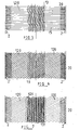
- the figure 5 shows the simplest support membrane architecture, the top and sides of said membrane being seen on plan.
- the flanks (11) are reinforced by a single radial ply (120) of reinforcing elements (15) with a brittle core of the same constitution as those previously described but radial.
- Said radial ply is also a crown ply as it is axially continuous with rod (2) with a bead (2) of membrane M.
- the crown (1) of said membrane is complemented by a hooping ply (13) arranged radially below the membrane support web (14), said shrink web being formed of reinforcing elements so that the breaking force per cm of web is a linear function of the inflation pressure p 1 of the tire cavity, the angular coefficient of the representative straight line being equal to 0.05 and the ordinate at the origin of said straight line being equal to 0.3 ⁇ 10 5 Pa, the tire concerned being a "heavy-weight" tire.
- FIG. 6 On the figure 6 is shown a membrane architecture with two continuous plies (120) of rod (2) rod (2), formed of reinforcing elements (15) brittle soul of the same constitution as those described above, but crossed a web to the next by making with the circumferential direction an angle, measured in the equatorial plane of the membrane, between 50 ° and 85 °, and more precisely equal to 60 °.
- the two plies (120) are sidewall reinforcement plies and crown reinforcing plies, the top being complementarily reinforced by a hooping ply (13) such as that shown on FIG. figure 5 and previously described.
- the architecture shown on the figure 7 , comprises a ply (120) for reinforcing the flank and the crown, because continuous rod (2) rod (2), said ply (120) being formed of the same brittle core elements as before, said elements being parallel to each other in the web and making with the circumferential direction an angle of 60 ° (but may be between 50 ° and 85 °), measured at the top of the membrane.
- the ply (120) is in the radially surmounted top of a crown ply (121) of defined axial width and composed of the same reinforcing elements as those of the ply (120), but crossed with them in the direction circumferential the same angle, but opposite direction.
- the web (121) may be radially surmounted by the support strip (14) provided with frustoconical relief elements (140) separated from each other by the recesses (141). These "plots” formed on the surface of the strip (14) circumferential rows, so that, between two rows of studs (140) axially adjacent, is disposed a banding strip (131) of circumferential cables, the assembly of which forms the sheet hooping (13).
- the sheet (121) can also be surmounted more simply by a hooping sheet such as that shown on the figure 5 and described in the passage corresponding to said figure.
Landscapes
- Engineering & Computer Science (AREA)
- Mechanical Engineering (AREA)
- Tires In General (AREA)
- Separation Using Semi-Permeable Membranes (AREA)
Applications Claiming Priority (3)
| Application Number | Priority Date | Filing Date | Title |
|---|---|---|---|
| FR9814695A FR2786131A1 (fr) | 1998-11-20 | 1998-11-20 | Membrane de soutien de bande de roulement |
| FR9814695 | 1998-11-20 | ||
| PCT/EP1999/008792 WO2000030877A1 (fr) | 1998-11-20 | 1999-11-16 | Membrane de soutien de bande de roulement |
Publications (2)
| Publication Number | Publication Date |
|---|---|
| EP1140528A1 EP1140528A1 (fr) | 2001-10-10 |
| EP1140528B1 true EP1140528B1 (fr) | 2009-01-21 |
Family
ID=9533048
Family Applications (1)
| Application Number | Title | Priority Date | Filing Date |
|---|---|---|---|
| EP99972585A Expired - Lifetime EP1140528B1 (fr) | 1998-11-20 | 1999-11-16 | Membrane de soutien de bande de roulement |
Country Status (10)
| Country | Link |
|---|---|
| US (1) | US6481481B2 (cg-RX-API-DMAC7.html) |
| EP (1) | EP1140528B1 (cg-RX-API-DMAC7.html) |
| JP (1) | JP4691256B2 (cg-RX-API-DMAC7.html) |
| AT (1) | ATE421435T1 (cg-RX-API-DMAC7.html) |
| AU (1) | AU756168B2 (cg-RX-API-DMAC7.html) |
| BR (1) | BR9915432A (cg-RX-API-DMAC7.html) |
| CA (1) | CA2351670C (cg-RX-API-DMAC7.html) |
| DE (1) | DE69940356D1 (cg-RX-API-DMAC7.html) |
| FR (1) | FR2786131A1 (cg-RX-API-DMAC7.html) |
| WO (1) | WO2000030877A1 (cg-RX-API-DMAC7.html) |
Families Citing this family (6)
| Publication number | Priority date | Publication date | Assignee | Title |
|---|---|---|---|---|
| FR2804067B1 (fr) * | 2000-01-20 | 2002-02-22 | Michelin Soc Tech | Membrane de soutien de bande de roulement |
| ES2304133T3 (es) * | 2000-11-30 | 2008-09-16 | Bridgestone Corporation | Camara de aire para neumatico de seguridad. |
| JP4571584B2 (ja) * | 2003-06-06 | 2010-10-27 | 株式会社ブリヂストン | 安全タイヤ用空気のう |
| FR3061674A1 (fr) * | 2017-01-12 | 2018-07-13 | Compagnie Generale Des Etablissements Michelin | Assemblage comprenant un tissu partiellement rompable et une structure porteuse |
| JP6911412B2 (ja) * | 2017-03-15 | 2021-07-28 | 横浜ゴム株式会社 | 中子支持式空気入りタイヤ |
| IT202000005185A1 (it) * | 2020-03-11 | 2021-09-11 | Cnh Ind Italia Spa | Ruota per veicolo comprendente un sistema di sicurezza migliorato |
Family Cites Families (6)
| Publication number | Priority date | Publication date | Assignee | Title |
|---|---|---|---|---|
| US3724521A (en) * | 1971-05-06 | 1973-04-03 | Exxon Research Engineering Co | Anti-flat device |
| DE2520321A1 (de) * | 1975-05-07 | 1976-11-18 | Continental Gummi Werke Ag | Fahrzeugluftreifen mit notlaufeinrichtung |
| US4164250A (en) * | 1976-11-15 | 1979-08-14 | Uniroyal, Inc. | Nail-deflecting, inner-tube assembly for run-flat tires |
| US4153095A (en) * | 1977-09-14 | 1979-05-08 | Uniroyal, Inc. | Pneumatic tire having a pneumatic safety insert with beads |
| FR2756221B1 (fr) | 1996-11-27 | 1998-12-31 | Michelin & Cie | Membrane de soutien de bande de roulement |
| FR2772666B1 (fr) | 1997-12-19 | 2000-01-21 | Michelin & Cie | Membrane de soutien de bande de roulement |
-
1998
- 1998-11-20 FR FR9814695A patent/FR2786131A1/fr active Pending
-
1999
- 1999-11-16 AT AT99972585T patent/ATE421435T1/de not_active IP Right Cessation
- 1999-11-16 BR BR9915432-3A patent/BR9915432A/pt not_active IP Right Cessation
- 1999-11-16 JP JP2000583728A patent/JP4691256B2/ja not_active Expired - Fee Related
- 1999-11-16 DE DE69940356T patent/DE69940356D1/de not_active Expired - Lifetime
- 1999-11-16 AU AU13833/00A patent/AU756168B2/en not_active Ceased
- 1999-11-16 EP EP99972585A patent/EP1140528B1/fr not_active Expired - Lifetime
- 1999-11-16 CA CA002351670A patent/CA2351670C/fr not_active Expired - Fee Related
- 1999-11-16 WO PCT/EP1999/008792 patent/WO2000030877A1/fr not_active Ceased
-
2001
- 2001-05-18 US US09/861,358 patent/US6481481B2/en not_active Expired - Fee Related
Also Published As
| Publication number | Publication date |
|---|---|
| US20010035247A1 (en) | 2001-11-01 |
| AU1383300A (en) | 2000-06-13 |
| EP1140528A1 (fr) | 2001-10-10 |
| AU756168B2 (en) | 2003-01-09 |
| WO2000030877A1 (fr) | 2000-06-02 |
| JP2002530236A (ja) | 2002-09-17 |
| ATE421435T1 (de) | 2009-02-15 |
| CA2351670A1 (fr) | 2000-06-02 |
| DE69940356D1 (de) | 2009-03-12 |
| FR2786131A1 (fr) | 2000-05-26 |
| US6481481B2 (en) | 2002-11-19 |
| CA2351670C (fr) | 2008-08-26 |
| BR9915432A (pt) | 2001-08-07 |
| JP4691256B2 (ja) | 2011-06-01 |
Similar Documents
| Publication | Publication Date | Title |
|---|---|---|
| CA2308037C (fr) | Armature de sommet pour pneumatique "poids-lourds" | |
| EP1035978B1 (fr) | Armature de sommet de pneumatique | |
| EP1040019B1 (fr) | Ensemle roulant avec membrane de soutien pour pneumatiques | |
| EP1257426B1 (fr) | Bourrelet de pneumatique avec nappes textiles | |
| EP1140528B1 (fr) | Membrane de soutien de bande de roulement | |
| CA2397542C (fr) | Bandage de soutien d'un pneumatique pour roulage a plat | |
| EP1353811B1 (fr) | Pneumatique avec anneau additionel | |
| CA2273510C (fr) | Membrane de soutien de bande de roulement | |
| EP0724973B1 (fr) | Bourrelets de pneumatique | |
| EP0999939B1 (fr) | Armature de sommet de pneumatique | |
| CA2332417C (fr) | Armature de sommet de pneumatique | |
| EP1261498B1 (fr) | Jante avec sieges inclines vers l'exterieur et ensembles comprenant une telle jante et un appui de soutien gonfle | |
| EP1185426A1 (fr) | Bourrelet sans tringle pour pneumatique |
Legal Events
| Date | Code | Title | Description |
|---|---|---|---|
| PUAI | Public reference made under article 153(3) epc to a published international application that has entered the european phase |
Free format text: ORIGINAL CODE: 0009012 |
|
| 17P | Request for examination filed |
Effective date: 20010620 |
|
| AK | Designated contracting states |
Kind code of ref document: A1 Designated state(s): AT BE CH CY DE DK ES FI FR GB GR IE IT LI LU MC NL PT SE |
|
| GRAP | Despatch of communication of intention to grant a patent |
Free format text: ORIGINAL CODE: EPIDOSNIGR1 |
|
| GRAS | Grant fee paid |
Free format text: ORIGINAL CODE: EPIDOSNIGR3 |
|
| RAP1 | Party data changed (applicant data changed or rights of an application transferred) |
Owner name: MICHELIN RECHERCHE ET TECHNIQUE S.A. Owner name: SOCIETE DE TECHNOLOGIE MICHELIN |
|
| GRAA | (expected) grant |
Free format text: ORIGINAL CODE: 0009210 |
|
| AK | Designated contracting states |
Kind code of ref document: B1 Designated state(s): AT BE CH CY DE DK ES FI FR GB GR IE IT LI LU MC NL PT SE |
|
| REG | Reference to a national code |
Ref country code: GB Ref legal event code: FG4D Free format text: NOT ENGLISH |
|
| REG | Reference to a national code |
Ref country code: CH Ref legal event code: EP |
|
| REG | Reference to a national code |
Ref country code: IE Ref legal event code: FG4D Free format text: LANGUAGE OF EP DOCUMENT: FRENCH |
|
| REF | Corresponds to: |
Ref document number: 69940356 Country of ref document: DE Date of ref document: 20090312 Kind code of ref document: P |
|
| PG25 | Lapsed in a contracting state [announced via postgrant information from national office to epo] |
Ref country code: NL Free format text: LAPSE BECAUSE OF FAILURE TO SUBMIT A TRANSLATION OF THE DESCRIPTION OR TO PAY THE FEE WITHIN THE PRESCRIBED TIME-LIMIT Effective date: 20090121 |
|
| NLV1 | Nl: lapsed or annulled due to failure to fulfill the requirements of art. 29p and 29m of the patents act | ||
| PG25 | Lapsed in a contracting state [announced via postgrant information from national office to epo] |
Ref country code: FI Free format text: LAPSE BECAUSE OF FAILURE TO SUBMIT A TRANSLATION OF THE DESCRIPTION OR TO PAY THE FEE WITHIN THE PRESCRIBED TIME-LIMIT Effective date: 20090121 Ref country code: ES Free format text: LAPSE BECAUSE OF FAILURE TO SUBMIT A TRANSLATION OF THE DESCRIPTION OR TO PAY THE FEE WITHIN THE PRESCRIBED TIME-LIMIT Effective date: 20090502 |
|
| REG | Reference to a national code |
Ref country code: IE Ref legal event code: FD4D |
|
| PG25 | Lapsed in a contracting state [announced via postgrant information from national office to epo] |
Ref country code: SE Free format text: LAPSE BECAUSE OF FAILURE TO SUBMIT A TRANSLATION OF THE DESCRIPTION OR TO PAY THE FEE WITHIN THE PRESCRIBED TIME-LIMIT Effective date: 20090421 Ref country code: PT Free format text: LAPSE BECAUSE OF FAILURE TO SUBMIT A TRANSLATION OF THE DESCRIPTION OR TO PAY THE FEE WITHIN THE PRESCRIBED TIME-LIMIT Effective date: 20090622 Ref country code: AT Free format text: LAPSE BECAUSE OF FAILURE TO SUBMIT A TRANSLATION OF THE DESCRIPTION OR TO PAY THE FEE WITHIN THE PRESCRIBED TIME-LIMIT Effective date: 20090121 |
|
| PG25 | Lapsed in a contracting state [announced via postgrant information from national office to epo] |
Ref country code: IE Free format text: LAPSE BECAUSE OF FAILURE TO SUBMIT A TRANSLATION OF THE DESCRIPTION OR TO PAY THE FEE WITHIN THE PRESCRIBED TIME-LIMIT Effective date: 20090121 Ref country code: DK Free format text: LAPSE BECAUSE OF FAILURE TO SUBMIT A TRANSLATION OF THE DESCRIPTION OR TO PAY THE FEE WITHIN THE PRESCRIBED TIME-LIMIT Effective date: 20090121 |
|
| PLBE | No opposition filed within time limit |
Free format text: ORIGINAL CODE: 0009261 |
|
| STAA | Information on the status of an ep patent application or granted ep patent |
Free format text: STATUS: NO OPPOSITION FILED WITHIN TIME LIMIT |
|
| 26N | No opposition filed |
Effective date: 20091022 |
|
| BERE | Be: lapsed |
Owner name: MICHELIN RECHERCHE ET TECHNIQUE S.A. Effective date: 20091130 Owner name: SOC. DE TECHNOLOGIE MICHELIN Effective date: 20091130 |
|
| PG25 | Lapsed in a contracting state [announced via postgrant information from national office to epo] |
Ref country code: MC Free format text: LAPSE BECAUSE OF NON-PAYMENT OF DUE FEES Effective date: 20091130 |
|
| REG | Reference to a national code |
Ref country code: CH Ref legal event code: PL |
|
| GBPC | Gb: european patent ceased through non-payment of renewal fee |
Effective date: 20091116 |
|
| PG25 | Lapsed in a contracting state [announced via postgrant information from national office to epo] |
Ref country code: LI Free format text: LAPSE BECAUSE OF NON-PAYMENT OF DUE FEES Effective date: 20091130 Ref country code: GR Free format text: LAPSE BECAUSE OF FAILURE TO SUBMIT A TRANSLATION OF THE DESCRIPTION OR TO PAY THE FEE WITHIN THE PRESCRIBED TIME-LIMIT Effective date: 20090422 Ref country code: CH Free format text: LAPSE BECAUSE OF NON-PAYMENT OF DUE FEES Effective date: 20091130 Ref country code: BE Free format text: LAPSE BECAUSE OF NON-PAYMENT OF DUE FEES Effective date: 20091130 |
|
| PG25 | Lapsed in a contracting state [announced via postgrant information from national office to epo] |
Ref country code: GB Free format text: LAPSE BECAUSE OF NON-PAYMENT OF DUE FEES Effective date: 20091116 |
|
| PGFP | Annual fee paid to national office [announced via postgrant information from national office to epo] |
Ref country code: DE Payment date: 20101119 Year of fee payment: 12 |
|
| PGFP | Annual fee paid to national office [announced via postgrant information from national office to epo] |
Ref country code: IT Payment date: 20101122 Year of fee payment: 12 |
|
| PG25 | Lapsed in a contracting state [announced via postgrant information from national office to epo] |
Ref country code: LU Free format text: LAPSE BECAUSE OF NON-PAYMENT OF DUE FEES Effective date: 20091116 |
|
| PG25 | Lapsed in a contracting state [announced via postgrant information from national office to epo] |
Ref country code: CY Free format text: LAPSE BECAUSE OF FAILURE TO SUBMIT A TRANSLATION OF THE DESCRIPTION OR TO PAY THE FEE WITHIN THE PRESCRIBED TIME-LIMIT Effective date: 20090121 |
|
| PGFP | Annual fee paid to national office [announced via postgrant information from national office to epo] |
Ref country code: FR Payment date: 20111130 Year of fee payment: 13 |
|
| REG | Reference to a national code |
Ref country code: FR Ref legal event code: ST Effective date: 20130731 |
|
| PG25 | Lapsed in a contracting state [announced via postgrant information from national office to epo] |
Ref country code: IT Free format text: LAPSE BECAUSE OF NON-PAYMENT OF DUE FEES Effective date: 20121116 |
|
| REG | Reference to a national code |
Ref country code: DE Ref legal event code: R119 Ref document number: 69940356 Country of ref document: DE Effective date: 20130601 |
|
| PG25 | Lapsed in a contracting state [announced via postgrant information from national office to epo] |
Ref country code: DE Free format text: LAPSE BECAUSE OF NON-PAYMENT OF DUE FEES Effective date: 20130601 |
|
| PG25 | Lapsed in a contracting state [announced via postgrant information from national office to epo] |
Ref country code: FR Free format text: LAPSE BECAUSE OF NON-PAYMENT OF DUE FEES Effective date: 20121130 |