EP1139542A2 - A compressor and an electric motor - Google Patents
A compressor and an electric motor Download PDFInfo
- Publication number
- EP1139542A2 EP1139542A2 EP01303003A EP01303003A EP1139542A2 EP 1139542 A2 EP1139542 A2 EP 1139542A2 EP 01303003 A EP01303003 A EP 01303003A EP 01303003 A EP01303003 A EP 01303003A EP 1139542 A2 EP1139542 A2 EP 1139542A2
- Authority
- EP
- European Patent Office
- Prior art keywords
- electric motor
- stator
- rotor
- housing
- compressor
- Prior art date
- Legal status (The legal status is an assumption and is not a legal conclusion. Google has not performed a legal analysis and makes no representation as to the accuracy of the status listed.)
- Withdrawn
Links
Images



Classifications
-
- H—ELECTRICITY
- H02—GENERATION; CONVERSION OR DISTRIBUTION OF ELECTRIC POWER
- H02K—DYNAMO-ELECTRIC MACHINES
- H02K5/00—Casings; Enclosures; Supports
- H02K5/04—Casings or enclosures characterised by the shape, form or construction thereof
- H02K5/06—Cast metal casings
-
- H—ELECTRICITY
- H02—GENERATION; CONVERSION OR DISTRIBUTION OF ELECTRIC POWER
- H02K—DYNAMO-ELECTRIC MACHINES
- H02K1/00—Details of the magnetic circuit
- H02K1/06—Details of the magnetic circuit characterised by the shape, form or construction
- H02K1/12—Stationary parts of the magnetic circuit
- H02K1/18—Means for mounting or fastening magnetic stationary parts on to, or to, the stator structures
- H02K1/185—Means for mounting or fastening magnetic stationary parts on to, or to, the stator structures to outer stators
-
- H—ELECTRICITY
- H02—GENERATION; CONVERSION OR DISTRIBUTION OF ELECTRIC POWER
- H02K—DYNAMO-ELECTRIC MACHINES
- H02K1/00—Details of the magnetic circuit
- H02K1/06—Details of the magnetic circuit characterised by the shape, form or construction
- H02K1/12—Stationary parts of the magnetic circuit
- H02K1/20—Stationary parts of the magnetic circuit with channels or ducts for flow of cooling medium
-
- H—ELECTRICITY
- H02—GENERATION; CONVERSION OR DISTRIBUTION OF ELECTRIC POWER
- H02K—DYNAMO-ELECTRIC MACHINES
- H02K3/00—Details of windings
- H02K3/02—Windings characterised by the conductor material
-
- H—ELECTRICITY
- H02—GENERATION; CONVERSION OR DISTRIBUTION OF ELECTRIC POWER
- H02K—DYNAMO-ELECTRIC MACHINES
- H02K7/00—Arrangements for handling mechanical energy structurally associated with dynamo-electric machines, e.g. structural association with mechanical driving motors or auxiliary dynamo-electric machines
- H02K7/14—Structural association with mechanical loads, e.g. with hand-held machine tools or fans
Definitions
- a compressor comprises:
- the weight of the entire compressor decreases substantially in proportion to the total volume of the windings. This is because, while the light-metal conductor wire differs from a copper wire in the value of electric resistance and accordingly in the range of effective sectional area properly set for handling lower voltages, it has a specific gravity smaller than that of a copper wire.
- using an aluminum wire makes it possible to realize a soft winding and thus facilitates the winding operation and subsequent re-forming operation, as compared with a copper wire. This also helps increase the slot space rate. Further, using a Litz wire as the light-metal wire is particularly preferable in a case where a larger wire diameter is required for the low-voltage electric motor, because the skin effect is less significant.
- a compressor comprises:
- the cavity, notch, or hole is formed with ease from a group of holes drilled in the laminated plate material, of which the cavity may be formed so as to lie scattered therearound as desired.
- the cavity, notch, and hole are essentially different than a cooling hole formed in the stator or rotor of a conventional compressor designed for a refrigeration cycle.
- the latter is formed for the purpose of cooling the electric motor by passing a refrigerant therethrough. That is, the former can be made as large as possible in size and number insofar as strength, safety, electric motor efficiency, and other factors concerning the compressor are maintained at adequate levels.
- the weight of the entire compressor decreases in proportion to the total volume of the cavity, notch, or hole.
- a compressor comprises:
- the axial notch or hole can be made larger in size and number than a conventional cooling hole. This makes it possible to reduce the weight of the compressor to a minimum. Simultaneously, this helps increase the passage area of the sound deadening path and thus obtain sufficient refrigerant noise suppression effect.
- the sound deadening path may preferably be realized as a path extending forwardly only partway and having its opening in the refrigerant admission direction, as a path which is so shaped that its width decreases gradually from its refrigerant-admission side to its refrigerant-discharge side, or as a through path having an expansion chamber partway along its length.
- a sound deadening path thus designed exerts interference- or expansion-based excellent noise suppression characteristics.
- a compressor comprises:
- This construction requires one fewer bolted positions in contrast to conventional cases where a stator needs to be bolted to a housing at four positions because it cannot be shrinkage-fitted thereto for reasons of material of the housing and the stator. This helps reduce the number of bolts and thick-walled portions necessary for bolting. This in turn helps reduce the weight of the entire compressor, as well as the number of constituent components and assembly man-hours, thereby achieving cost reduction.
- the winding of the stator is formed from a star-shaped three-phase winding, it may preferably be wound in parallel. This makes it possible to create three boundary portions for the winding groups arranged along the circumferentially outermost portion of the stator. Then, by arranging the above-described bolted positions so that they face their corresponding boundary portions, any possible mutual interference of the winding groups can be avoided. Thus, there is no need for the bolted portions to protrude greatly outward to avoid such interference. This makes the stator smaller and thus helps reduce the weight of the electric motor.
- an electric motor comprises a rotor and a stator, the stator having a winding formed from a light-metal conductor wire having a specific gravity smaller than that of a copper wire.
- any of the above-described compressors employs, as a power source, a battery which is moved concomitantly therewith, and has an electric motor and a compression mechanism driven by the electric motor housed in a housing.
- a battery which is moved concomitantly therewith, and has an electric motor and a compression mechanism driven by the electric motor housed in a housing.
- Such a construction is suitable for use as an air-conditioning mechanism in vehicles ranging up to large-sized passenger cars.
- Fig. 1 shows a scroll-type compressor according to one embodiment of the invention.
- the compressor has a housing 1 for accommodating a compression mechanism 2 and an electric motor 3 for driving same through a crank shaft 4.
- the crank shaft 4 includes a main shaft 4a on its one end on the side of the compression mechanism 2.
- On one side in a lengthwise direction in the housing 1 is a main bearing member 5, while a sub bearing member 6 is provided on the other side within the housing 1, for supporting the opposite ends of the crank shaft 4.
- a stationary scroll 7 is bolted to the main bearing member 5. Between the main bearing member 5 and the stationary scroll 7 is inserted a rotating scroll 8, which meshes with the stationary scroll 7 so as to form a scroll-type compression mechanism 2. Between the rotating scroll 8 and the main bearing member 5 is disposed a rotation restricting mechanism 9 such as an Oldham's ring or the like for preventing the rotating scroll 8 from rotating and for guiding it in circular orbital motion.
- a rotation restricting mechanism 9 such as an Oldham's ring or the like for preventing the rotating scroll 8 from rotating and for guiding it in circular orbital motion.
- a compression chamber 11, formed between the stationary scroll 7 and the rotating scroll 8 is moved from the outer periphery side to the central region, with a gradual reduction of the volume thereof.
- An electric motor 3 is located between the main bearing member 5 and the sub bearing member 6, and is composed of a stator 3a fixedly attached to the housing 1 and a rotor 3b formed integrally around the outer periphery of the central portion of the crank shaft 4.
- the rotor 3b has a balance weight 16 formed in the outer peripheral portion of its upper and lower end faces. Providing the balance weight 16 assures high stability in the rotary motion of the rotor 3b and the crank shaft 4, and thereby stable circular orbital motion is imparted to the rotating scroll 8.
- a pump 17 is provided at one end of the crank shaft 4 opposite from the main shaft 4a.
- Oil 19 is sucked from an oil reservoir 18 disposed at the bottom portion of the housing 1 into the pump 17, and is supplied through an oil feeding hole 21 piercing through the crank shaft 4 to bearing portions 22 of the components constituting the compression mechanism 2 and the sliding portions of the compression mechanism 2.
- the oil 19 having passed therethrough is subjected to supply pressure, gravity, or the like, and thereby flows through the bearing portion 22 into the housing 1, and then drips and eventually collects in the oil reservoir 18.
- Refrigerant gas discharged from the compression mechanism 2 passes through and thereby cools the electric-motor 3. Then, the refrigerant gas is discharged through a connection port 23 to the outside of the housing 1 so as to serve for the refrigeration cycle.
- the housing 1 is formed as a pressure-tight container and is thus thick-walled. Therefore, if it is made of an iron-based material, an undesirable increase in the weight is unavoidable.
- this embodiment of the invention employs, for the housing of the compressor, a light-metal material having a specific gravity smaller than that of an iron-based material, for example, aluminum.
- a housing made of aluminum needs to have a thicker wall than an iron-based housing and is nevertheless advantageous from a weight standpoint.
- using an iron-based material may not lead to any serious problem in achieving weight reduction, and therefore a metal material used for the housing 1 is not limited to light metal.
- the housing 1 is made of light metal and thus cannot be shrinkage-fitted to the iron-based stator 3a. Therefore, the stator 3a is, at several positions around its circumferential surface, fixed by bolts 26 to a stepped surface 25 formed in an inner surface of the body 1a of the housing 1.
- the housing 1 is composed of the body 1a and panels 1b and 1c. The panels 1b and 1c are fixed to each end thereof at several positions around their circumferential surfaces by bolts 27.
- the main bearing member 5 is fitted tightly in the inner periphery of the panel 1b disposed on the side of the compression mechanism 2. Between the main bearing member 5 and the panel 1b is inserted the stationary scroll 7 with a tight fit and fixed by a bolt 28.
- the sub bearing member 6 is formed integrally with the body 1a of the housing 1.
- the entire construction of the present invention is not limited to the concrete example described above; it may include, except for those described hereinafter, any conventionally-known or later-disclosed structural combination.
- the stator 3a is, at equally spaced three positions around its outer circumferential surface, bolted to the housing 1.
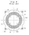
- a conventional stator 103a is fixed to a housing at four positions by bolts 126. That is, this embodiment of the invention requires one fewer bolted portions than the conventional case. This helps reduce the number of bolts 26 and the thick-walled portions 1d and 3a1 of the body 1a of the housing 1 and the stator 3a formed for bolting shown in Figs. 1 and 2A. This in turn helps reduce the weight of the entire compressor, as well as the number of constituent components and assembly man-hours, thereby achieving cost reduction.
- the stator 3a is so designed that, when it is used with the rotor 3b of conventional type that carries four magnetic poles formed by permanent magnets or the like, there is no possibility of occurrence of the moment at which its three bolted positions and the plurality of magnetic poles of the rotor 3b are concurrently opposed to one another.
- the four bolted positions of the stator 103a and the four magnetic poles of the rotor 103b are concurrently opposed to one another.
- the winding 31 of the stator 3a is formed from a star-shaped three-phase winding.
- the winding 31 by forming the winding 31 into a parallel winding, it is possible to create boundary portions 31b at three equi-spaced positions on the boundaries among groups of windings 31a arranged along the circumferentially outermost portion.
- the above-described bolted positions by arranging the above-described bolted positions so that they individually face their corresponding boundary portions 31b, any possible mutual interference of the winding groups 31a can be avoided.
- the bolted portions to protrude greatly outward.
- Figs. 9 and 10 the star-shaped three-phase winding is wound in series so that the four bolted positions individually face their corresponding boundary portions of the four winding groups 131 arranged along the outermost periphery.
- Fig. 2A shows the winding position of the winding group 31a wound in 24 slots
- Fig. 2B shows the winding position of the winding group 31a wound in 12 slots.
- the boundary portions 31b do not necessarily have to be equi-spaced so long as they are properly arranged so as to face their corresponding bolted positions.
- At least one of the stator 3a and the rotor 3b of the electric motor 3 has at least one of a cavity, a notch axially arranged continuously or discontinuously, and a hole formed on its surface in the circumferential direction.
- the stator 3a has, in several positions around its outer periphery, a series of notches 41 arranged continuously.
- the stator 3a has, around its outer periphery, a plurality of notches 41 and holes 42 arranged continuously or penetrating completely.
- these notches 41 and holes 42 are so arranged as to face their corresponding boundary portions of the slots 3e in order to avoid interference with the winding 31 in the stator 3a.
- the arrangement position and the size thereof may preferably be so determined as to achieve well-balanced rotary motion around the crank shaft 4. This eliminates the need for a balance weight 16 or makes its configuration simple.
- the cavity, the notch 41, and the hole 42 are formed with ease from a group of holes drilled in the laminated plate material, of which the cavity may be formed so as to lie scattered therearound as desired.
- the cavity, the notch 41, and the hole 42 are essentially different than the notch and cooling hole formed in the stator or rotor of a conventional compressor designed for a refrigeration cycle.
- the latter are formed for the purpose of achieving oil separation and cooling of the electric motor by passing a refrigerant therethrough. That is, the former can be made as large as possible in size and number insofar as strength, safety, electric motor efficiency, and other factors concerning the compressor are maintained at adequate levels.
- the weight of the entire compressor decreases in proportion to the total volume of the cavity, the notch 41, and the hole 42.
- at least one of the notch 41 and the hole 42 thus designed can be provided in the circumferential direction to form an axial sound deadening path for conveying a refrigerant.
- a hole 42 is provided that is interrupted halfway and receives a refrigerant flowing in the direction indicated by an arrow.
- a hole 42 is so formed as to have an expansion chamber 42a partway along its length and is capable of functioning for a refrigerant irrespective of its flowing direction (as indicated by two arrows) .
- a hole 42 is so shaped that its width decreases gradually from one end to the other end.
- a refrigerant is introduced from the larger opening thereof and is then discharged from the smaller opening.
- the sound deadening path 51 thus designed may be formed between the notch 41 and the housing 1. These holes are drilled in the laminated steel plate during the punching operation with a cutting tool separately provided therefor.
- the axial notch 41 or the hole 42 can be made larger in size and number than a conventional cooling hole. That is, it is possible to increase the passage area of the sound deadening path 51 and thus obtain sufficient refrigerant noise suppression effect.
- the winding 31 of the stator 3a is formed from a light-metal conductor wire having a specific gravity smaller than that of a copper wire.
- the rotor 3b also has a winding, by forming the winding from a light-metal conductor wire, it is possible to achieve further weight reduction.
- the panels 1b and 1c of the housing 1 each have a leg 52 formed integrally therewith.
- the leg 52 is coupled through a damping block 53 to a mounting seat 54.
- this bracket is coupled through the damping block to the mounting seat.
- the light-metal conductor wire differs from a copper wire in the value of electric resistance and accordingly in the range of effective sectional area properly set for handling lower voltages, it has a specific gravity smaller than that of a copper wire. Accordingly, the weight of the compressor and the electric motor decreases substantially in proportion to the total volume of the windings 31.
- the low-voltage electric motor is used at, for example, 50V or below and at 50A or above, and its maximum power output is set at nearly 2500W.
- Such a construction is suitable for use as an air-conditioning mechanism in vehicles ranging up to large-sized passenger cars in which a battery is used as a power source for driving the electric motor 3.
- an aluminum wire having effective sectional area ranging from 5mm 2 to 10mm 2 from the viewpoint of prevention of fusion and energization efficiency.
- Using an aluminum wire provides approximately a 20 to 30% drop in the weight.
- the use of aluminum wires makes it possible to make the winding 31 soft and thus facilitates the winding operation and subsequent re-forming operation, as compared with a copper wire.
- using a Litz wire as the light-metal wire is particularly preferable in a case where a larger wire diameter is required for the low-voltage electric motor, because it is free from reduction in effective sectional area.
- the skin effect obtained in cases where electric current is supplied at a high frequency is defined by the following formula.
- the career frequency is set to a range of about 2.5 KHz to 20 KHz.
- the career frequency is set at 5 KHz, it is preferable to employ a Litz wire having a core diameter of ⁇ 1.88 mm or below.
- the stator 3a of the electric motor 3 is made of an iron-based material
- the housing 1, in particular, its body 1a is made of aluminum
- the housing 1 is, when molded, provided integrally with the stator 3a without performing bolting. This eliminates the need for a bolt or a thick-walled portion necessary for bolting and thus leads to a reduction in the weight of the compressor as a whole. This also helps reduce the number of constituent components and assembly man-hours, thereby achieving cost reduction.
- the present invention provides a compressor and an electric motor that are lighter in weight. These constructions, when used for applications involving movement, allow reduction in the moving load and thus make a notable contribution to the conservation of energy. It is of course possible to attain practical advantages when they are used for applications independent of movement.
- the application of the present invention is not limited to the above-described scroll-type compressor.
- the invention is applicable to various types of compressors having a compression mechanism of rotary-type, reciprocating-type, or any other type, and an electric motor for driving the compression mechanism combined together, or applicable to a construction employing a vertical compression mechanism.
Landscapes
- Engineering & Computer Science (AREA)
- Power Engineering (AREA)
- Compressor (AREA)
- Motor Or Generator Frames (AREA)
- Motor Or Generator Cooling System (AREA)
- Exhaust Silencers (AREA)
- Applications Or Details Of Rotary Compressors (AREA)
- Iron Core Of Rotating Electric Machines (AREA)
- Windings For Motors And Generators (AREA)
- Connection Of Motors, Electrical Generators, Mechanical Devices, And The Like (AREA)
- Permanent Magnet Type Synchronous Machine (AREA)
Abstract
Description
| Conductivity [S/m] | Permeability [H/m] | |
| Aluminum [mm] | 3.96 E+07 | 1.25666 E-06 |
| Copper [mm] | 5.76 E+07 | 1.25663 E-06 |


Claims (27)
- A compressor, comprising:a housing (1);a compression mechanism (2) accommodated in the housing; anda low-voltage electric motor (3) for driving the compression mechanism, the electric motor including a rotor (3b) and a stator (3a), the stator having a winding (31) formed from a light-metal conductor wire having a specific gravity smaller than that of a copper wire.
- A compressor according to claim 1, wherein the electric motor is used at 50V or below and at 50A or above.
- A compressor according to claim 1 or 2, wherein the light-metal conductor wire is an aluminum wire having effective sectional area ranging from 5mm2 to 10mm2.
- A compressor according to claim 1 or 2, wherein the light-metal conductor wire is a Litz wire.
- A compressor, comprising:a housing (1);a compression mechanism (2) accommodated in the housing; andan electric motor (3) including a rotor (3b) and a stator (3a) for driving the compression mechanism, at least one of the stator and the rotor of the electric motor having at least one of cavities, axially extending notches (41), and holes (42) formed on a surface thereof in a circumferential direction to achieve weight reduction.
- A compressor according to claim 5, wherein one of the notches and the holes forms an axial sound deadening path (51) for conveying a refrigerant therethrough.
- A compressor according to claim 6, wherein the sound deadening path is formed such as to have an opening in a refrigerant admission direction and is interrupted halfway.
- A compressor according to claim 6, wherein the sound deadening path is so shaped that its width decreases gradually from a refrigerant-admission side thereof to a refrigerant-discharge side thereof.
- A compressor according to claim 6, wherein the sound deadening path is a through path which has an expansion chamber partway along its length.
- A compressor, comprising:a housing (1) made of aluminum;a compression mechanism (2) accommodated in the housing; andan electric motor (3) for driving the compression mechanism, the electric motor including a rotor (3b) and a stator (3a) made of iron-based material and bolted to a stepped surface (25) of an inner periphery of the housing at equally-spaced three positions around an outer periphery thereof.
- A compressor according to claim 10, wherein the rotor has two or four magnetic poles.
- A compressor according to claim 10 or 11, wherein the stator has a star-shaped three-phase winding and is wound in parallel, and
wherein the bolted positions are so located as to face their corresponding boundary portions (31b) of winding groups (31a) arranged along a circumferentially outermost portion of the stator. - A compressor, comprising:a housing (1) made of aluminum;a compression mechanism (2) accommodated in the housing; andan electric motor (3) for driving the compression mechanism, the electric motor including a rotor (3b) and a stator (3a) made of iron-based material and cast in an inner periphery of the housing.
- A compressor according to any preceding claim, wherein the compressor is driven by a battery movable concomitantly therewith.
- A low-voltage electric motor, comprising a rotor and a stator, the stator having a winding formed from a light-metal conductor wire having a specific gravity smaller than that of a copper wire.
- An electric motor according to claim 15, wherein the electric motor is used at 50V or below and at 50A or above.
- An electric motor according to claim 16, wherein the light-metal conductor wire is an aluminum wire having effective sectional area ranging from 5mm2 to 10mm2.
- An electric motor according to claim 16, wherein the light-metal conductor wire is a Litz wire.
- An electric motor, comprising a rotor and a stator, at least one of the stator and the rotor having at least one of cavities, axially extending notches, and holes formed on a surface thereof in a circumferential direction to achieve weight reduction.
- An electric motor according to claim 19, wherein one of the notches and the holes forms an axial sound deadening path for conveying a refrigerant therethrough.
- An electric motor according to claim 20, wherein the sound deadening path is formed such as to have an opening in a refrigerant admission direction and is interrupted halfway.
- An electric motor according to claim 20, wherein the sound deadening path is so shaped that its width decreases gradually from a refrigerant-admission side thereof to a refrigerant-discharge side thereof.
- An electric motor according to claim 20, wherein the sound deadening path is a through path which has an expansion chamber partway along its length.
- An electric motor, comprising:a casing made of aluminum; anda stator and a rotor each accommodated in the casing, the stator being made of iron-based material and bolted to a stepped surface of an inner periphery of the casing at equally-spaced three positions around an outer periphery thereof.
- An electric motor according to claim 24, wherein the rotor has two or four magnetic poles.
- An electric motor according to claim 25, wherein the stator has a star-shaped three-phase winding and is wound in parallel, and
wherein the bolted positions are so located as to face their corresponding boundary portions of winding groups arranged along a circumferentially outermost portion of the stator. - An electric motor, comprising:a casing made of aluminum; anda stator and a rotor each accommodated in the casing, the stator being made of iron-based material and cast in an inner periphery of the casing.
Applications Claiming Priority (2)
| Application Number | Priority Date | Filing Date | Title |
|---|---|---|---|
| JP2000098888A JP2001280249A (en) | 2000-03-31 | 2000-03-31 | Compressors and electric motors |
| JP2000098888 | 2000-03-31 |
Publications (2)
| Publication Number | Publication Date |
|---|---|
| EP1139542A2 true EP1139542A2 (en) | 2001-10-04 |
| EP1139542A3 EP1139542A3 (en) | 2002-08-21 |
Family
ID=18613315
Family Applications (1)
| Application Number | Title | Priority Date | Filing Date |
|---|---|---|---|
| EP01303003A Withdrawn EP1139542A3 (en) | 2000-03-31 | 2001-03-29 | A compressor and an electric motor |
Country Status (3)
| Country | Link |
|---|---|
| US (1) | US6544009B2 (en) |
| EP (1) | EP1139542A3 (en) |
| JP (1) | JP2001280249A (en) |
Cited By (6)
| Publication number | Priority date | Publication date | Assignee | Title |
|---|---|---|---|---|
| EP1533527A1 (en) * | 2003-11-21 | 2005-05-25 | Kabushiki Kaisha Toyota Jidoshokki | Assembly method of motor housing and motor stator of sealed type compressor |
| FR2903246A1 (en) * | 2006-06-30 | 2008-01-04 | Leroy Somer Moteurs | Electric motor for driving compressor, has stator, whose windings are partially made of aluminum wires covered with alumina layer, and electrical conductors arranged in electrically insulating maintaining part that is engaged in opening |
| EP2061138A3 (en) * | 2007-11-15 | 2012-07-11 | Sundyne Corporation | Stator winding method and apparatus |
| FR2975240A1 (en) * | 2011-05-11 | 2012-11-16 | Renault Sa | ROTATING ELECTRIC MACHINE |
| CN104662775A (en) * | 2012-09-18 | 2015-05-27 | 株式会社明电舍 | Stator fixing structure |
| WO2017032429A1 (en) * | 2015-08-27 | 2017-03-02 | Bitzer Kühlmaschinenbau Gmbh | Compressor |
Families Citing this family (81)
| Publication number | Priority date | Publication date | Assignee | Title |
|---|---|---|---|---|
| JP3671849B2 (en) * | 2001-03-14 | 2005-07-13 | 松下電器産業株式会社 | Compressor with built-in motor and mobile vehicle using it |
| JP4777541B2 (en) * | 2001-06-08 | 2011-09-21 | パナソニック株式会社 | Compressor with built-in electric motor and mobile vehicle equipped with this |
| JP4667651B2 (en) * | 2001-06-08 | 2011-04-13 | パナソニック株式会社 | Compressor with built-in electric motor and mobile vehicle equipped with this |
| US7690451B2 (en) * | 2002-05-31 | 2010-04-06 | Ise Corporation | System and method for powering accessories in a hybrid vehicle |
| US7391129B2 (en) * | 2002-05-31 | 2008-06-24 | Ise Corporation | System and method for powering accessories in a hybrid vehicle |
| US7119454B1 (en) | 2002-05-31 | 2006-10-10 | Ise Corporation | System and method for powering accessories in a hybrid vehicle |
| JP4250389B2 (en) * | 2002-08-29 | 2009-04-08 | 日本電産株式会社 | motor |
| JP2004183499A (en) * | 2002-11-29 | 2004-07-02 | Denso Corp | Electric compressor |
| JP2004183632A (en) * | 2002-12-06 | 2004-07-02 | Matsushita Electric Ind Co Ltd | Method and apparatus for recovering supply liquid from compression mechanism |
| JP2004183631A (en) * | 2002-12-06 | 2004-07-02 | Matsushita Electric Ind Co Ltd | Electric compressor |
| JP2004197567A (en) * | 2002-12-16 | 2004-07-15 | Matsushita Electric Ind Co Ltd | Compressor |
| JP2004201428A (en) * | 2002-12-19 | 2004-07-15 | Matsushita Electric Ind Co Ltd | Electric motor |
| US6655165B1 (en) * | 2002-12-19 | 2003-12-02 | Nissan Technical Center North America, Inc. | Air conditioner with power recovery device having a sound suppression device |
| US7029242B2 (en) * | 2003-11-14 | 2006-04-18 | Tecumseh Products Company | Hermetic compressor with one-quarter wavelength tuner |
| US7198130B2 (en) * | 2004-09-28 | 2007-04-03 | Oshkosh Truck Corporation | V-drive motor arrangement |
| JP2006348928A (en) * | 2004-10-14 | 2006-12-28 | Matsushita Electric Ind Co Ltd | Compressor |
| KR20060039621A (en) * | 2004-11-03 | 2006-05-09 | 엘지전자 주식회사 | Linear compressor |
| US7841845B2 (en) * | 2005-05-16 | 2010-11-30 | Emerson Climate Technologies, Inc. | Open drive scroll machine |
| JP4810961B2 (en) * | 2005-10-13 | 2011-11-09 | ダイキン工業株式会社 | Compressor |
| JP2007174827A (en) * | 2005-12-22 | 2007-07-05 | Nissan Motor Co Ltd | Electric motor stator structure |
| US7840395B2 (en) * | 2006-03-10 | 2010-11-23 | Edsa Micro Corporation | Systems and methods for predictive monitoring including real-time strength and security analysis in an electrical power distribution system |
| US20160246905A1 (en) | 2006-02-14 | 2016-08-25 | Power Analytics Corporation | Method For Predicting Arc Flash Energy And PPE Category Within A Real-Time Monitoring System |
| US8170856B2 (en) | 2006-04-12 | 2012-05-01 | Power Analytics Corporation | Systems and methods for real-time advanced visualization for predicting the health, reliability and performance of an electrical power system |
| US20090113049A1 (en) * | 2006-04-12 | 2009-04-30 | Edsa Micro Corporation | Systems and methods for real-time forecasting and predicting of electrical peaks and managing the energy, health, reliability, and performance of electrical power systems based on an artificial adaptive neural network |
| US9557723B2 (en) | 2006-07-19 | 2017-01-31 | Power Analytics Corporation | Real-time predictive systems for intelligent energy monitoring and management of electrical power networks |
| US8131401B2 (en) * | 2006-07-19 | 2012-03-06 | Power Analytics Corporation | Real-time stability indexing for intelligent energy monitoring and management of electrical power network system |
| US20170046458A1 (en) | 2006-02-14 | 2017-02-16 | Power Analytics Corporation | Systems and methods for real-time dc microgrid power analytics for mission-critical power systems |
| US8036872B2 (en) * | 2006-03-10 | 2011-10-11 | Edsa Micro Corporation | Systems and methods for performing automatic real-time harmonics analyses for use in real-time power analytics of an electrical power distribution system |
| US7844439B2 (en) * | 2006-03-10 | 2010-11-30 | Edsa Micro Corporation | Systems and methods for real-time protective device evaluation in an electrical power distribution system |
| US9092593B2 (en) | 2007-09-25 | 2015-07-28 | Power Analytics Corporation | Systems and methods for intuitive modeling of complex networks in a digital environment |
| KR100663641B1 (en) * | 2006-04-06 | 2007-01-05 | 주식회사 아모텍 | Manufacturing method of integrated stator, BCD motor of radial core type double rotor method using same and manufacturing method thereof |
| US7693608B2 (en) * | 2006-04-12 | 2010-04-06 | Edsa Micro Corporation | Systems and methods for alarm filtering and management within a real-time data acquisition and monitoring environment |
| CA2648953C (en) * | 2006-04-12 | 2016-06-14 | Edsa Micro Corporation | Systems and methods for performing automatic real-time harmonics analyses for use in real-time power analytics of an electrical power distribution system |
| KR20080006733A (en) * | 2006-07-13 | 2008-01-17 | 삼성광주전자 주식회사 | Hermetic compressor and its manufacturing method |
| US8775934B2 (en) * | 2006-07-19 | 2014-07-08 | Power Analytics Corporation | Systems and methods for creation of a schematic user interface for monitoring and predicting the real-time health, reliability and performance of an electrical power system |
| US8229722B2 (en) * | 2007-05-16 | 2012-07-24 | Power Analytics Corporation | Electrical power system modeling, design, analysis, and reporting via a client-server application framework |
| JP5067022B2 (en) * | 2007-06-04 | 2012-11-07 | 株式会社豊田自動織機 | Electric compressor |
| US8155943B2 (en) * | 2007-10-12 | 2012-04-10 | Power Analytics Corporation | Systems and methods for automatically converting CAD drawing files into intelligent objects with database connectivity for the design, analysis, and simulation of electrical power systems |
| KR100885447B1 (en) | 2007-10-29 | 2009-02-24 | 엘지전자 주식회사 | Motor and compressor comprising the same |
| JP2009118712A (en) * | 2007-11-09 | 2009-05-28 | Toyota Motor Corp | Rotating electric machine |
| KR101404749B1 (en) * | 2007-11-28 | 2014-06-12 | 엘지전자 주식회사 | Motor for compressor and recipro compressor having the same |
| US8390167B2 (en) * | 2007-11-22 | 2013-03-05 | Lg Electronics Inc. | Motor for compressor and hermetic compressor having the same |
| KR101404748B1 (en) * | 2007-11-26 | 2014-06-12 | 엘지전자 주식회사 | Motor for compressor and reciprocating compressor using the same |
| US8441165B2 (en) * | 2007-11-22 | 2013-05-14 | Lg Electronics Inc. | Motor for compressor and hermetic compressor having the same |
| WO2009066875A2 (en) * | 2007-11-22 | 2009-05-28 | Lg Electronics Inc. | Motor for compressor and hermetic compressor having the same |
| US7777386B2 (en) * | 2008-02-01 | 2010-08-17 | Emerson Electric Co. | Electric machine |
| KR100931361B1 (en) * | 2008-03-31 | 2009-12-11 | 한라공조주식회사 | Field coil assembly of electromagnetic clutch for compressor |
| EP2113991B1 (en) * | 2008-05-02 | 2015-07-15 | Siemens Aktiengesellschaft | Cast stator of a dynamoelectric machine |
| US7709992B2 (en) * | 2008-07-31 | 2010-05-04 | Emerson Electric Co. | Electric machine |
| WO2010058478A1 (en) * | 2008-11-21 | 2010-05-27 | トヨタ自動車株式会社 | Breather device and drive device |
| US8143759B2 (en) * | 2009-04-30 | 2012-03-27 | Hamilton Sundstrand Corporation | Laminated stator assembly |
| CN102472284A (en) * | 2009-08-06 | 2012-05-23 | 艾默生电气公司 | Screw compressor with radially configured motor windings |
| US8222788B2 (en) * | 2009-09-01 | 2012-07-17 | Emerson Electric Co. | Electric machine |
| US20110082597A1 (en) | 2009-10-01 | 2011-04-07 | Edsa Micro Corporation | Microgrid model based automated real time simulation for market based electric power system optimization |
| CN103236752B (en) | 2010-08-20 | 2014-11-26 | 株式会社藤仓 | Electromotor |
| JP2012100380A (en) * | 2010-10-29 | 2012-05-24 | Nippon Steel Corp | Stator for inner rotor motor |
| DE202011111030U1 (en) | 2010-12-22 | 2018-07-05 | Fisher & Paykel Appliances Limited | improved device, motor or stator |
| CN102437659A (en) * | 2011-12-23 | 2012-05-02 | 芜湖博耐尔汽车电气系统有限公司 | Stator structure of electric compressor |
| WO2013145459A1 (en) * | 2012-03-29 | 2013-10-03 | アイシン・エィ・ダブリュ株式会社 | Coil |
| KR101955263B1 (en) * | 2012-09-12 | 2019-03-11 | 삼성전자주식회사 | Motor and washing machine having the same |
| US10148140B2 (en) * | 2013-01-28 | 2018-12-04 | Denso Corporation | Motor |
| ITCR20130007A1 (en) * | 2013-02-21 | 2014-08-22 | E M B Di Bergamaschini Alfonso | CENTRIFUGAL PUMP FOR ASPIRATION OF AERIFORMS FLUIDS |
| CN105190204B (en) | 2013-03-11 | 2017-05-31 | 特灵国际有限公司 | Control and Operation of Variable Frequency Drives |
| US9407194B2 (en) | 2013-03-15 | 2016-08-02 | Emerson Climate Technologies, Inc. | System and method for protection of a compressor with an aluminum winding motor |
| JP6330345B2 (en) * | 2014-01-29 | 2018-05-30 | 株式会社デンソー | Compressor mounting structure |
| WO2015136930A1 (en) * | 2014-03-13 | 2015-09-17 | 国立大学法人神戸大学 | Battery inspection device and battery inspection method |
| JP2016073120A (en) * | 2014-09-30 | 2016-05-09 | アイシン・エィ・ダブリュ株式会社 | Stator for rotary electric machine |
| US10336299B2 (en) | 2014-11-11 | 2019-07-02 | Mitsuba Corporation | Brushless wiper motor |
| JP6696399B2 (en) * | 2016-10-20 | 2020-05-20 | トヨタ自動車株式会社 | Reinforcement member mounting structure |
| JP2018087536A (en) | 2016-11-29 | 2018-06-07 | 三菱重工サーマルシステムズ株式会社 | Rotary compressor system, rotary compressor and motor |
| DE102016223968A1 (en) * | 2016-12-01 | 2018-06-07 | Volkswagen Aktiengesellschaft | Assembled housing assembly for an electrical machine and manufacturing process |
| US20220404070A1 (en) * | 2017-12-18 | 2022-12-22 | Daikin Industries, Ltd. | Air conditioner |
| JP7207852B2 (en) * | 2018-02-08 | 2023-01-18 | Ntn株式会社 | Vehicle motor drive |
| JP7317525B2 (en) * | 2019-03-08 | 2023-07-31 | 三菱重工サーマルシステムズ株式会社 | electric compressor |
| JP7502587B2 (en) * | 2019-03-12 | 2024-06-19 | ダイキン工業株式会社 | Compressor |
| JP7302464B2 (en) * | 2019-12-19 | 2023-07-04 | トヨタ自動車株式会社 | Rotating electric machine |
| JP7542203B2 (en) * | 2020-02-19 | 2024-08-30 | パナソニックIpマネジメント株式会社 | Compressor |
| JP7347299B2 (en) | 2020-03-31 | 2023-09-20 | 株式会社豊田自動織機 | electric compressor |
| JP2022047760A (en) * | 2020-09-14 | 2022-03-25 | 日本電産株式会社 | Rotary electric machine |
| JP7469405B2 (en) * | 2022-08-25 | 2024-04-16 | 愛知電機株式会社 | Electric motors and compressors |
| JP7826910B2 (en) | 2022-11-16 | 2026-03-10 | トヨタ自動車株式会社 | Electric motor mounting structure |
Family Cites Families (32)
| Publication number | Priority date | Publication date | Assignee | Title |
|---|---|---|---|---|
| US3450338A (en) | 1967-12-20 | 1969-06-17 | Gen Electric | Hermetic refrigerant motor compressor unit |
| US3610784A (en) * | 1970-03-19 | 1971-10-05 | Tecumseh Products Co | Electric motor and compressor construction |
| US3922575A (en) * | 1972-03-30 | 1975-11-25 | Emerson Electric Co | Stator assembly with bore sleeve |
| US3942055A (en) * | 1974-10-16 | 1976-03-02 | General Electric Company | Hermetic motor stator |
| JPS6218940A (en) | 1985-07-15 | 1987-01-27 | Mitsubishi Electric Corp | Closed-type rotary compressor |
| JPS6373840A (en) | 1986-09-12 | 1988-04-04 | Matsushita Seiko Co Ltd | Speed governor |
| US4864177A (en) * | 1987-12-16 | 1989-09-05 | Yang Tai Her | Stator lamination design for two-pole single-phase induction motor |
| US5006045A (en) * | 1987-12-24 | 1991-04-09 | Seiko Epson Corporation | Scroll compressor with reverse rotation speed limiter |
| JPH029983A (en) * | 1988-06-28 | 1990-01-12 | Matsushita Electric Ind Co Ltd | Hermetic electric compressor |
| US5173629A (en) * | 1989-11-13 | 1992-12-22 | A. O. Smith Corporation | Electric motor stator assembly with square edged stator plates |
| JPH03213681A (en) | 1990-01-17 | 1991-09-19 | Mitsubishi Heavy Ind Ltd | Enclosed type compressor |
| JPH0626473A (en) | 1992-07-09 | 1994-02-01 | Daikin Ind Ltd | Scroll compressor |
| US5385453A (en) * | 1993-01-22 | 1995-01-31 | Copeland Corporation | Multiple compressor in a single shell |
| US5514922A (en) | 1993-02-08 | 1996-05-07 | Sanden Corporation | Hermetic motor driven fluid apparatus having improved insulating structure |
| US5354182A (en) * | 1993-05-17 | 1994-10-11 | Vickers, Incorporated | Unitary electric-motor/hydraulic-pump assembly with noise reduction features |
| US5339652A (en) * | 1993-09-17 | 1994-08-23 | Tecumseh Products Company | Sound and vibration absorbing damper |
| US5535967A (en) * | 1993-12-20 | 1996-07-16 | Alliedsignal Inc. | Floating speed electrically driven suction system |
| CH689976A5 (en) | 1994-05-24 | 2000-02-29 | Bobst Sa | Device for controlling the taking of a plate element by clips in a such material processing machine. |
| JPH08214514A (en) | 1995-02-01 | 1996-08-20 | Mitsubishi Electric Corp | Squirrel cage induction motor, stator casting mold and stator casting method |
| JPH0932729A (en) * | 1995-07-19 | 1997-02-04 | Mitsubishi Heavy Ind Ltd | Motor-driven compressor |
| JPH0932765A (en) | 1995-07-21 | 1997-02-04 | Mitsubishi Heavy Ind Ltd | Scroll-type electric compressor |
| JPH09131001A (en) | 1995-10-30 | 1997-05-16 | Hitachi Ltd | Hermetic compressor |
| JPH09163791A (en) * | 1995-12-07 | 1997-06-20 | Sanden Corp | Driving method for motor-driven compressor and drive device |
| US5767607A (en) * | 1996-11-27 | 1998-06-16 | Emerson Electric Co. | Weight optimized rotors |
| JPH10169554A (en) | 1996-12-06 | 1998-06-23 | Toshiba Ave Corp | Hermetic compressor |
| AUPO478297A0 (en) | 1997-01-24 | 1997-02-20 | Commonwealth Scientific And Industrial Research Organisation | Improvements in high speed electric motors |
| TW380329B (en) * | 1997-04-16 | 2000-01-21 | Japan Servo | Permanent-magnet revolving electrodynamic machine with a concentrated winding stator |
| US6232731B1 (en) | 1997-06-26 | 2001-05-15 | Electric Boat Corporation | Multi-channel motor winding configuration and pulse width modulated controller |
| WO1999003188A1 (en) | 1997-07-09 | 1999-01-21 | Sl Montevideo Technology, Inc. | Brushless dc permanent magnet motors for traction drive systems |
| JPH11294361A (en) | 1998-04-09 | 1999-10-26 | Sharp Corp | Hermetic compressor and method for fixing stator of hermetic compressor |
| US6123167A (en) | 1998-06-11 | 2000-09-26 | Trw Inc. | Electric steering motor with one-piece metal shell |
| US6315528B1 (en) * | 1999-05-27 | 2001-11-13 | Scroll Technologies | Terminal connection in small area of scroll compressor and method for carrying out same |
-
2000
- 2000-03-31 JP JP2000098888A patent/JP2001280249A/en not_active Withdrawn
-
2001
- 2001-03-29 EP EP01303003A patent/EP1139542A3/en not_active Withdrawn
- 2001-03-29 US US09/819,627 patent/US6544009B2/en not_active Expired - Fee Related
Cited By (12)
| Publication number | Priority date | Publication date | Assignee | Title |
|---|---|---|---|---|
| EP1533527A1 (en) * | 2003-11-21 | 2005-05-25 | Kabushiki Kaisha Toyota Jidoshokki | Assembly method of motor housing and motor stator of sealed type compressor |
| US7363696B2 (en) | 2003-11-21 | 2008-04-29 | Kabushiki Kaisha Toyota Jidoshokki | Method of assembling a sealed type motor-driven compressor |
| FR2903246A1 (en) * | 2006-06-30 | 2008-01-04 | Leroy Somer Moteurs | Electric motor for driving compressor, has stator, whose windings are partially made of aluminum wires covered with alumina layer, and electrical conductors arranged in electrically insulating maintaining part that is engaged in opening |
| EP2061138A3 (en) * | 2007-11-15 | 2012-07-11 | Sundyne Corporation | Stator winding method and apparatus |
| FR2975240A1 (en) * | 2011-05-11 | 2012-11-16 | Renault Sa | ROTATING ELECTRIC MACHINE |
| CN104662775A (en) * | 2012-09-18 | 2015-05-27 | 株式会社明电舍 | Stator fixing structure |
| EP2899849A4 (en) * | 2012-09-18 | 2016-05-25 | Meidensha Electric Mfg Co Ltd | STATOR FASTENING STRUCTURE |
| CN104662775B (en) * | 2012-09-18 | 2018-07-10 | 株式会社明电舍 | The fixture construction of stator |
| US10770933B2 (en) | 2012-09-18 | 2020-09-08 | Meidensha Corporation | Stator fixing structure |
| WO2017032429A1 (en) * | 2015-08-27 | 2017-03-02 | Bitzer Kühlmaschinenbau Gmbh | Compressor |
| RU2702226C2 (en) * | 2015-08-27 | 2019-10-07 | Битцер Кюльмашиненбау Гмбх | Compressor |
| US11277044B2 (en) | 2015-08-27 | 2022-03-15 | Bitzer Kuehlmaschinenbau Gmbh | Compressor |
Also Published As
| Publication number | Publication date |
|---|---|
| JP2001280249A (en) | 2001-10-10 |
| US20010036414A1 (en) | 2001-11-01 |
| US6544009B2 (en) | 2003-04-08 |
| EP1139542A3 (en) | 2002-08-21 |
Similar Documents
| Publication | Publication Date | Title |
|---|---|---|
| US6544009B2 (en) | Compressor and electric motor | |
| CN101465586B (en) | Self-starting type permanent magnet synchronous motor and a compressor using the same | |
| JP2710827B2 (en) | Scroll fluid machine | |
| CN101997369A (en) | Self-starting permanent magnet synchronous motor and compressor and refrigeration cycle using the same | |
| EP2240995B1 (en) | Motor for compressor and hermetic compressor having the same | |
| JP2004278374A (en) | Scroll compressor | |
| KR20030031837A (en) | Self-starting synchronous motor and compressor using the same | |
| JP2006333627A (en) | Self-starting synchronous motor, method for manufacturing the same, and compressor | |
| JP5359112B2 (en) | Axial gap type rotating electrical machine and compressor using the same | |
| KR20130011646A (en) | Electronic compressor | |
| WO2005078279A1 (en) | Motor-driven pump unit | |
| JP2006230087A (en) | Electric motor, compressor and air conditioner | |
| JP2004052657A (en) | Hermetic compressor | |
| JP2006266210A (en) | Compressor | |
| JPWO2003065549A1 (en) | Axial gap motor | |
| JP2004056887A (en) | Single-phase or two-phase self-starting synchronous motor and compressor using the same | |
| WO1997047884A2 (en) | Apparatus for providing pressurized liquid to a device, high speed flood cooled motor/generator therefor | |
| JP5138236B2 (en) | Rotary compressor | |
| KR102172260B1 (en) | Motor and compressor having thereof | |
| JP5131032B2 (en) | Electric compressor | |
| CA2605457A1 (en) | High-torque switched reluctance motor | |
| WO2008062789A1 (en) | Rotary compressor and refrigeration cycle device | |
| JP2005002799A (en) | Compressor | |
| US20250105688A1 (en) | Radial flux electric motor with airgap cooling | |
| JP2003343439A (en) | Compressor |
Legal Events
| Date | Code | Title | Description |
|---|---|---|---|
| PUAI | Public reference made under article 153(3) epc to a published international application that has entered the european phase |
Free format text: ORIGINAL CODE: 0009012 |
|
| AK | Designated contracting states |
Kind code of ref document: A2 Designated state(s): AT BE CH CY DE DK ES FI FR GB GR IE IT LI LU MC NL PT SE TR |
|
| AX | Request for extension of the european patent |
Free format text: AL;LT;LV;MK;RO;SI |
|
| RIC1 | Information provided on ipc code assigned before grant |
Free format text: 7H 02K 1/18 A, 7H 02K 1/20 B, 7H 02K 3/02 B, 7H 02K 5/06 B |
|
| PUAL | Search report despatched |
Free format text: ORIGINAL CODE: 0009013 |
|
| AK | Designated contracting states |
Kind code of ref document: A3 Designated state(s): AT BE CH CY DE DK ES FI FR GB GR IE IT LI LU MC NL PT SE TR |
|
| AX | Request for extension of the european patent |
Free format text: AL;LT;LV;MK;RO;SI |
|
| 17P | Request for examination filed |
Effective date: 20030130 |
|
| AKX | Designation fees paid |
Designated state(s): DE FR IT |
|
| 17Q | First examination report despatched |
Effective date: 20040322 |
|
| GRAP | Despatch of communication of intention to grant a patent |
Free format text: ORIGINAL CODE: EPIDOSNIGR1 |
|
| STAA | Information on the status of an ep patent application or granted ep patent |
Free format text: STATUS: THE APPLICATION IS DEEMED TO BE WITHDRAWN |
|
| 18D | Application deemed to be withdrawn |
Effective date: 20050830 |