EP1138961A1 - Fastening element for a vaporizer - Google Patents
Fastening element for a vaporizer Download PDFInfo
- Publication number
- EP1138961A1 EP1138961A1 EP01107598A EP01107598A EP1138961A1 EP 1138961 A1 EP1138961 A1 EP 1138961A1 EP 01107598 A EP01107598 A EP 01107598A EP 01107598 A EP01107598 A EP 01107598A EP 1138961 A1 EP1138961 A1 EP 1138961A1
- Authority
- EP
- European Patent Office
- Prior art keywords
- fastening element
- shaft
- element according
- sleeve
- bore
- Prior art date
- Legal status (The legal status is an assumption and is not a legal conclusion. Google has not performed a legal analysis and makes no representation as to the accuracy of the status listed.)
- Granted
Links
- 239000006200 vaporizer Substances 0.000 title 1
- 239000013536 elastomeric material Substances 0.000 claims abstract description 7
- 239000004033 plastic Substances 0.000 claims description 12
- 229920001971 elastomer Polymers 0.000 claims description 6
- 239000002184 metal Substances 0.000 claims description 6
- 238000001816 cooling Methods 0.000 claims description 4
- 229920002725 thermoplastic elastomer Polymers 0.000 claims description 3
- 239000000806 elastomer Substances 0.000 claims description 2
- 239000000463 material Substances 0.000 claims 2
- 238000001125 extrusion Methods 0.000 claims 1
- 238000002347 injection Methods 0.000 description 2
- 239000007924 injection Substances 0.000 description 2
- 230000005540 biological transmission Effects 0.000 description 1
- 230000000295 complement effect Effects 0.000 description 1
- 238000000748 compression moulding Methods 0.000 description 1
- 238000013016 damping Methods 0.000 description 1
- 230000000694 effects Effects 0.000 description 1
- 238000007373 indentation Methods 0.000 description 1
- 238000009413 insulation Methods 0.000 description 1
- 229920001169 thermoplastic Polymers 0.000 description 1
- 239000004416 thermosoftening plastic Substances 0.000 description 1
- 238000004073 vulcanization Methods 0.000 description 1
Images

Classifications
-
- F—MECHANICAL ENGINEERING; LIGHTING; HEATING; WEAPONS; BLASTING
- F25—REFRIGERATION OR COOLING; COMBINED HEATING AND REFRIGERATION SYSTEMS; HEAT PUMP SYSTEMS; MANUFACTURE OR STORAGE OF ICE; LIQUEFACTION SOLIDIFICATION OF GASES
- F25D—REFRIGERATORS; COLD ROOMS; ICE-BOXES; COOLING OR FREEZING APPARATUS NOT OTHERWISE PROVIDED FOR
- F25D23/00—General constructional features
- F25D23/06—Walls
- F25D23/065—Details
- F25D23/067—Supporting elements
-
- F—MECHANICAL ENGINEERING; LIGHTING; HEATING; WEAPONS; BLASTING
- F16—ENGINEERING ELEMENTS AND UNITS; GENERAL MEASURES FOR PRODUCING AND MAINTAINING EFFECTIVE FUNCTIONING OF MACHINES OR INSTALLATIONS; THERMAL INSULATION IN GENERAL
- F16B—DEVICES FOR FASTENING OR SECURING CONSTRUCTIONAL ELEMENTS OR MACHINE PARTS TOGETHER, e.g. NAILS, BOLTS, CIRCLIPS, CLAMPS, CLIPS OR WEDGES; JOINTS OR JOINTING
- F16B19/00—Bolts without screw-thread; Pins, including deformable elements; Rivets
- F16B19/04—Rivets; Spigots or the like fastened by riveting
- F16B19/08—Hollow rivets; Multi-part rivets
- F16B19/10—Hollow rivets; Multi-part rivets fastened by expanding mechanically
- F16B19/1027—Multi-part rivets
- F16B19/1036—Blind rivets
- F16B19/1081—Blind rivets fastened by a drive-pin
-
- F—MECHANICAL ENGINEERING; LIGHTING; HEATING; WEAPONS; BLASTING
- F16—ENGINEERING ELEMENTS AND UNITS; GENERAL MEASURES FOR PRODUCING AND MAINTAINING EFFECTIVE FUNCTIONING OF MACHINES OR INSTALLATIONS; THERMAL INSULATION IN GENERAL
- F16B—DEVICES FOR FASTENING OR SECURING CONSTRUCTIONAL ELEMENTS OR MACHINE PARTS TOGETHER, e.g. NAILS, BOLTS, CIRCLIPS, CLAMPS, CLIPS OR WEDGES; JOINTS OR JOINTING
- F16B21/00—Means for preventing relative axial movement of a pin, spigot, shaft or the like and a member surrounding it; Stud-and-socket releasable fastenings
- F16B21/06—Releasable fastening devices with snap-action
-
- F—MECHANICAL ENGINEERING; LIGHTING; HEATING; WEAPONS; BLASTING
- F16—ENGINEERING ELEMENTS AND UNITS; GENERAL MEASURES FOR PRODUCING AND MAINTAINING EFFECTIVE FUNCTIONING OF MACHINES OR INSTALLATIONS; THERMAL INSULATION IN GENERAL
- F16B—DEVICES FOR FASTENING OR SECURING CONSTRUCTIONAL ELEMENTS OR MACHINE PARTS TOGETHER, e.g. NAILS, BOLTS, CIRCLIPS, CLAMPS, CLIPS OR WEDGES; JOINTS OR JOINTING
- F16B5/00—Joining sheets or plates, e.g. panels, to one another or to strips or bars parallel to them
- F16B5/02—Joining sheets or plates, e.g. panels, to one another or to strips or bars parallel to them by means of fastening members using screw-thread
- F16B5/0258—Joining sheets or plates, e.g. panels, to one another or to strips or bars parallel to them by means of fastening members using screw-thread using resiliently deformable sleeves, grommets or inserts
-
- F—MECHANICAL ENGINEERING; LIGHTING; HEATING; WEAPONS; BLASTING
- F25—REFRIGERATION OR COOLING; COMBINED HEATING AND REFRIGERATION SYSTEMS; HEAT PUMP SYSTEMS; MANUFACTURE OR STORAGE OF ICE; LIQUEFACTION SOLIDIFICATION OF GASES
- F25D—REFRIGERATORS; COLD ROOMS; ICE-BOXES; COOLING OR FREEZING APPARATUS NOT OTHERWISE PROVIDED FOR
- F25D23/00—General constructional features
- F25D23/006—General constructional features for mounting refrigerating machinery components
Definitions
- the invention relates to a fastening element, preferably for fastening a Evaporator plate on the rear wall of the refrigerated goods chamber of a refrigerator, with a insertable into a bore or a recess and held in this Shaft.
- airborne noise emissions for example in Form of crackling noises arise when the evaporator plate, such as in EP 0 641 941 B1, with relatively rigid fastening bolts in Retractions or depressions of the rear wall of the cooling chamber is attached.
- the evaporator shrinks during the cooling phase and it expands during the defrost phase. This creates relative movements to the attachment points.
- the hole edges of the evaporator plate freeze with the relatively rigid mounting bolts.
- the relative movement of the evaporator will through the fastening bolts on their connection points in the recesses or recesses in the rear wall. By suddenly overcoming the Stiction can then cause noise emissions (crackling noises) in a fraction of a second. be generated.
- the object of the invention is to provide a simply designed fastener to create the kind specified that the attachment of objects in in a way that dampens the transmission of vibrations and / or tension between the parts fastened together is avoided be prevented, and the disruptive airborne noise emissions.
- this object is achieved in that the shaft of one Cuff or socket made of elastomeric material is bordered with a Holding device is provided for the part to be fastened.
- the shaft serves as the holder on the load-bearing part while vibrating through the sleeve or bushing dampened from elastomeric material and at least tension caused by it can be reduced.
- the holding device provided on the cuff or socket can be made from a There are grooves that surround the edge of a hole in the part to be fastened.
- the cuff or socket is expediently provided with at its outer end a frustoconical section to which the groove connects.
- This Embodiment allows the bore of the part to be fastened over the Push on the frustoconical section until it snaps into the groove.
- the shaft can consist of a metal screw with a head.
- the shaft can also consist of a plastic bolt provided with a head, which is expediently hollow.
- the shaft made of plastic or metal can be non-positive and / or positive in the Bore or recess can be kept.
- the shaft and the bore or recess with at least one eccentric section are provided in such a way that the shaft by about a quarter turn in the Hole or recess can be determined.
- the shaft is braced in the hole or recess in this place, with the eccentric section of the shaft in the bore or the recess is not only held positively but also positively, because the corresponding wall section of the bore or recess through Flow borders the eccentric section.
- the screw or the plastic bolt can be made from a thermoplastic Injection molded elastomer existing sleeve or bushing.
- the cuff or sleeve made of elastomeric material can also stand alone prefabricated and then attached to the screw or bolt, whereby then the screw or bolt is tied to one Prevent the sleeve or sleeve from moving or emigrating.
- the Cuff or bushing can also be used, for example, by vulcanization and compression molding be made.
- the thickness of the jacket of the sleeve or the sleeve is chosen so that the elastomeric material has the desired damping effect or tension is able to compensate.
- the diameter of the groove is expediently approximately twice the diameter of the screw or bolt in it Level.
- At least three and preferably four screws or bolts in recesses or boreholes of the rear wall of a refrigerated goods chamber of a refrigerator are and on their sleeves or bushings an evaporator or an evaporator plate is snapped in such a way that its or its holding holes grip in the grooves.
- Becomes an evaporator or an evaporator plate or board in this way preferably by four rubber mounting points connected to the back of the refrigerated goods container, vibrations of the connecting element described is only transmitted in a damped form, so that good noise insulation is achieved.
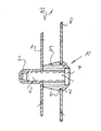
- the plastic shell 1 is the rear wall of the Provide the refrigerated goods chamber of a refrigerator with a hole-shaped indentation 2.
- the shaft of a metal screw 3 is held with a end head 4 is provided.
- the shaft 3 of the metal screw penetrates one Cuff 5 made of elastomeric material, in the illustrated embodiment a thermoplastic rubber.
- the cuff 5 is provided with an annular groove 6.
- the end section 7 of the rubber sleeve 5 is shown in the Formed frustoconical.
- the head 4 of the screw 3 is approximately complementary recess of the rubber sleeve 5 embedded.
- the substantially rectangular evaporator plate 8 in the area their corners are provided with holes that over the frustoconical Sections 7 of the rubber sleeves 5 are pushed in such a way that they snap into the ring grooves 6.
- the section of the sleeves 5 between the rear wall 1 and the evaporator plate 8 can taper like a truncated cone in the manner shown.
- the shaft consists of a total of 20 designated fastener from a hollow injection molded part made of plastic 21. Between a collar 22 of the plastic bolt and the end head 23 is a profiled sleeve on the hollow shaft part 24 of the plastic bolt 25 held from a thermoplastic rubber.
- the cuff 25 is with a Provide annular groove 26 which connects to a rounded portion 27 at the end.
- the cuff 25 is provided with a widened annular foot part 28, with which it lies sealingly against the rear wall 1.
- the shafts of the screws 3 and the plastic bolt 21 can by non-positive Insert, screw in or twist in the holes or recesses 2 must be set.
Landscapes
- Engineering & Computer Science (AREA)
- General Engineering & Computer Science (AREA)
- Mechanical Engineering (AREA)
- Chemical & Material Sciences (AREA)
- Combustion & Propulsion (AREA)
- Physics & Mathematics (AREA)
- Thermal Sciences (AREA)
- Cold Air Circulating Systems And Constructional Details In Refrigerators (AREA)
- Connection Of Plates (AREA)
- Refrigerator Housings (AREA)
- Devices That Are Associated With Refrigeration Equipment (AREA)
- Feeding And Controlling Fuel (AREA)
Abstract
Description
Die Erfindung betrifft ein Befestigungselement, vorzugsweise zum Befestigen einer Verdampferplatte an der Rückwand der Kühlgutkammer eines Kühlgeräts, mit einem in eine Bohrung oder eine Ausnehmung einsetzbaren und in dieser gehalterten Schaft.The invention relates to a fastening element, preferably for fastening a Evaporator plate on the rear wall of the refrigerated goods chamber of a refrigerator, with a insertable into a bore or a recess and held in this Shaft.
Es besteht das Bedürfnis, Teile in der Weise aneinander zu befestigen, daß diese Relativbewegungen gegeneinander durchführen können, ohne Verspannungen hervorzurufen, die zu Luftschallemissionen führen können. Ist das befestigte Teil an dem tragenden Teil in zwei oder mehr Punkten befestigt, ist es häufig erforderlich, daß sich das befestigte Teil relativ zu dem tragenden dehnen und schrumpfen kann, um Verspannungen zu vermeiden, welche die Ursache von störenden Luftschallemissionen sind.There is a need to attach parts to one another in such a way that they Can perform relative movements against each other without tension cause airborne noise emissions. Is the attached part on attached to the load-bearing part in two or more points, it is often necessary that the fastened part expands and shrinks relative to the load-bearing part can to avoid tension, which is the cause of disturbing airborne noise emissions are.
Insbesondere können bei Kühlgeräten Luftschallemissionen, beispielsweise in Form von Knackgeräuschen entstehen, wenn die Verdampferplatte, wie beispielsweise in EP 0 641 941 B1 beschrieben, mit relativ starren Befestigungsbolzen in Einziehungen oder Vertiefungen der Rückwand der Kühlkammer befestigt ist. Bei dem Betrieb des Geräts schrumpft der Verdampfer während der Kühlphase und er dehnt sich während der Abtauphase aus. Dadurch entstehen Relativbewegungen zu den Befestigungsstellen. Weiterhin können die Lochränder der Verdampferplatte mit den relativ starren Befestigungsbolzen vereisen. Durch die Relativbewegung des Verdampfers können dann die Vereisungsstellen unter Abgabe von Schallemissionen (Knackgeräusche) brechen. Die Relativbewegung des Verdampfers wird durch die Befestigungsbolzen auf deren Verbindungsstellen in den Einziehungen oder Vertiefungen der Rückwand übertragen. Durch schlagartiges Überwinden der Haftreibung können dann in Bruchteilen von Sekunden Schallemissionen (Knackgeräusche) erzeugt werden.In particular, airborne noise emissions, for example in Form of crackling noises arise when the evaporator plate, such as in EP 0 641 941 B1, with relatively rigid fastening bolts in Retractions or depressions of the rear wall of the cooling chamber is attached. At the operation of the device, the evaporator shrinks during the cooling phase and it expands during the defrost phase. This creates relative movements to the attachment points. Furthermore, the hole edges of the evaporator plate freeze with the relatively rigid mounting bolts. Through the relative movement of the evaporator can then the icing points with the emission of noise (Crackling) break. The relative movement of the evaporator will through the fastening bolts on their connection points in the recesses or recesses in the rear wall. By suddenly overcoming the Stiction can then cause noise emissions (crackling noises) in a fraction of a second. be generated.
Aufgabe der Erfindung ist es, ein einfach ausgestaltetes Befestigungselement der eingangs angegebenen Art zu schaffen, das eine Befestigung von Gegenständen in einer Weise ermöglicht, daß die Übertragung von Schwingungen gedämpft und/oder Verspannungen zwischen den aneinander befestigten Teilen vermieden werden, und das störende Luftschallemissionen verhindert.The object of the invention is to provide a simply designed fastener to create the kind specified that the attachment of objects in in a way that dampens the transmission of vibrations and / or tension between the parts fastened together is avoided be prevented, and the disruptive airborne noise emissions.
Erfindungsgemäß wird diese Aufgabe dadurch gelöst, daß der Schaft von einer Manschette oder Buchse aus elastomerem Material eingefaßt ist, die mit einer Halteeinrichtung für das zu befestigende Teil versehen ist.According to the invention, this object is achieved in that the shaft of one Cuff or socket made of elastomeric material is bordered with a Holding device is provided for the part to be fastened.
Bei dem erfindungsgemäßen Befestigungselement dient der Schaft der Halterung an dem tragenden Teil, während Schwingungen durch die Manschette oder Buchse aus elastomerem Material gedämpft und Verspannungen durch diese zumindest vermindert werden.In the fastening element according to the invention, the shaft serves as the holder on the load-bearing part while vibrating through the sleeve or bushing dampened from elastomeric material and at least tension caused by it can be reduced.
Die an der Manschette oder Buchse vorgesehene Halteeinrichtung kann aus einer Nut bestehen, die den Rand einer Bohrung des zu befestigenden Teils einfaßt.The holding device provided on the cuff or socket can be made from a There are grooves that surround the edge of a hole in the part to be fastened.
Zweckmäßigerweise ist die Manschette oder Buchse an ihrem äußeren Ende mit einem kegelstumpfförmigen Abschnitt versehen, an den die Nut anschließt. Diese Ausführungsform ermöglicht es, die Bohrung des zu befestigenden Teils über den kegelstumpfförmigen Abschnitt aufzuschieben, bis diese in die Nut einschnappt. The cuff or socket is expediently provided with at its outer end a frustoconical section to which the groove connects. This Embodiment allows the bore of the part to be fastened over the Push on the frustoconical section until it snaps into the groove.
Der Schaft kann aus einer mit einem Kopf versehenen Metallschraube bestehen. Der Schaft kann auch aus einem mit einem Kopf versehenen Kunststoffbolzen bestehen, der zweckmäßigerweise hohl ausgebildet ist.The shaft can consist of a metal screw with a head. The shaft can also consist of a plastic bolt provided with a head, which is expediently hollow.
Der Schaft aus Kunststoff oder Metall kann kraft- und/oder formschlüssig in der Bohrung oder Ausnehmung gehalten sein.The shaft made of plastic or metal can be non-positive and / or positive in the Bore or recess can be kept.
Nach einer weiteren Ausgestaltung der Erfindung ist vorgesehen, daß der Schaft und die Bohrung oder Ausnehmung mit mindestens einem exzentrischen Abschnitt in der Weise versehen sind, daß der Schaft etwa durch eine Vierteldrehung in der Bohrung oder Aussparung festlegbar ist. Durch Verdrehung des exzentrischen Abschnitts in der Bohrung oder der Aussparung findet eine Verspannung des Schafts in diesen statt, wobei der exzentrische Abschnitt des Schafts in der Bohrung oder der Aussparung nicht nur kraftschlüssig, sondern auch formschlüssig gehalten wird, weil der entsprechende Wandungsabschnitt der Bohrung oder Aussparung durch Fließen den exzentrischen Abschnitt einfaßt.According to a further embodiment of the invention it is provided that the shaft and the bore or recess with at least one eccentric section are provided in such a way that the shaft by about a quarter turn in the Hole or recess can be determined. By twisting the eccentric section the shaft is braced in the hole or recess in this place, with the eccentric section of the shaft in the bore or the recess is not only held positively but also positively, because the corresponding wall section of the bore or recess through Flow borders the eccentric section.
Die Schraube oder der Kunststoffbolzen können mit der aus einem thermoplastischen Elastomer bestehenden Manschette oder Buchse umspritzt sein.The screw or the plastic bolt can be made from a thermoplastic Injection molded elastomer existing sleeve or bushing.
Die Manschette oder Buchse aus elastomerem Material kann auch für sich allein vorgefertigt und dann auf die Schraube oder den Bolzen aufgesteckt sein, wobei dann die Schraube oder der Bolzen mit Bunden oder Köpfen versehen ist, um ein Verschieben oder Auswandern der Manschette oder Buchse zu verhindern. Die Manschette oder Buchse kann beispielsweise auch durch Vulkanisieren und Formpressen hergestellt sein.The cuff or sleeve made of elastomeric material can also stand alone prefabricated and then attached to the screw or bolt, whereby then the screw or bolt is tied to one Prevent the sleeve or sleeve from moving or emigrating. The Cuff or bushing can also be used, for example, by vulcanization and compression molding be made.
Die Dicke des Mantels der Manschette oder der Buchse ist so gewählt, daß das elastomere Material die gewünschte Dämpfungswirkung hat bzw. Verspannungen auszugleichen vermag. Zweckmäßigerweise ist der Durchmesser der Nut etwa doppelt so groß wie der Durchmesser der Schraube oder des Bolzens in deren Ebene. The thickness of the jacket of the sleeve or the sleeve is chosen so that the elastomeric material has the desired damping effect or tension is able to compensate. The diameter of the groove is expediently approximately twice the diameter of the screw or bolt in it Level.
Nach einer erfinderischen Ausgestaltung und Verwendung ist vorgesehen, daß mindestens drei und vorzugsweise vier Schrauben oder Bolzen in Einziehungen oder Bohrungen der Rückwand einer Kühlgutkammer eines Kühlgeräts gehaltert sind und auf deren Manschetten oder Buchsen ein Verdampfer bzw. eine Verdampferplatte in der Weise aufgerastet ist, daß dessen bzw. deren Haltebohrungen in den Nuten greifen. Wird ein Verdampfer bzw. eine Verdampferplatte oder -platine in dieser Weise durch vorzugsweise vier gummigelagerte Befestigunsgpunkte mit der Rückseite des Kühlgutbehälters verbunden, können Schwingungen von dem beschriebenen Verbindungselement nur in gedämpfter Form übertragen werden, so daß eine gute Geräuschdämmung erreicht wird. Weiterhin kann sich die Verdampferplatte allseitig ausdehnen und auch schwingen, so daß unerwünschte Knackgeräusche bei Temperaturschwankungen im Kühlgerät und Druckdifferenzen in den Verdampferkanälen vermieden werden.According to an inventive design and use, it is provided that at least three and preferably four screws or bolts in recesses or boreholes of the rear wall of a refrigerated goods chamber of a refrigerator are and on their sleeves or bushings an evaporator or an evaporator plate is snapped in such a way that its or its holding holes grip in the grooves. Becomes an evaporator or an evaporator plate or board in this way, preferably by four rubber mounting points connected to the back of the refrigerated goods container, vibrations of the connecting element described is only transmitted in a damped form, so that good noise insulation is achieved. Furthermore, the Extend the evaporator plate on all sides and also swing it, so that unwanted Crackling noises in the case of temperature fluctuations in the cooling unit and pressure differences be avoided in the evaporator channels.
Ausführungsbeispiele der Erfindung werden nachstehend anhand der Zeichnung näher erläutert. In dieser zeigt
- Fig. 1
- einen Schnitt durch einen Teil einer Verdampferplatte und einen Teil der Rückwand der Kühlgutkammer eines Kühlgeräts im Bereich eines beide verbindenden Befestigungselements und
- Fig. 2
- eine der Fig. 1 entsprechende Darstellung, bei der die Verdampferplatte mit der Rückwand der Kühlgutkammer durch ein anderes Befestigungselement verbunden ist.
- Fig. 1
- a section through part of an evaporator plate and part of the rear wall of the refrigerated goods chamber of a refrigerator in the region of a fastening element connecting both and
- Fig. 2
- 1 corresponding representation in which the evaporator plate is connected to the rear wall of the refrigerated goods chamber by another fastening element.
Bei der Ausführungsform nach Fig. 1 ist die Kunststoffschale 1 der Rückwand der
Kühlgutkammer eines Kühlgeräts mit einer lochförmigen Einziehung 2 versehen. In
dieser Einziehung 2 ist der Schaft einer Metallschraube 3 gehaltert, die mit einem
endseitigen Kopf 4 versehen ist. Der Schaft 3 der Metallschraube durchsetzt eine
Manschette 5 aus elastomerem Material, im dargestellten Ausführungsbeispiel aus
einem thermoplastischem Gummi. Die Manschette 5 ist mit einer Ringnut 6 versehen.
Der endseitige Abschnitt 7 der Gummimanschette 5 ist in der dargestellten
Weise kegelstumpfförmig ausgebildet. Der Kopf 4 der Schraube 3 ist in eine etwa
komplementäre Ausnehmung der Gummimanschette 5 eingebettet. Zur Befestigung
der Verdampferplatte 8 dienen vier insgesamt mit 10 bezeichnete Befestigungselemente,
wobei die im wesentlichen rechteckige Verdampferplatte 8 im Bereich
ihrer Ecken mit Bohrungen versehen ist, die über die kegelstumpfförmigen
Abschnitte 7 der Gummimanschetten 5 in der Weise aufgeschoben werden, daß sie
in die Ringnuten 6 einschnappen.In the embodiment according to FIG. 1, the plastic shell 1 is the rear wall of the
Provide the refrigerated goods chamber of a refrigerator with a hole-
Der Abschnitt der Manschetten 5 zwischen der Rückwand 1 und der Verdampferplatte
8 kann sich in der dargestellten Weise kegelstumpfartig verjüngen.The section of the sleeves 5 between the rear wall 1 and the
Bei dem Ausführungsbeispiel nach Fig. 2 besteht der Schaft des insgesamt mit 20
bezeichneten Befestigungselements aus einem hohlen Spritzgußteil aus Kunststoff
21. Zwischen einem Bund 22 des Kunststoffbolzens und dem endseitigen Kopf 23
ist auf dem hohlen Schaftteil 24 des Kunststoffbolzens eine profilierte Manschette
25 aus einem thermoplastischen Gummi gehaltert. Die Manschette 25 ist mit einer
Ringnut 26 versehen, die an einen endseitigen abgerundeten Abschnitt 27 anschließt.
Die Manschette 25 ist mit einem verbreiterten ringförmigen Fußteil 28 versehen,
mit der diese dichtend an der Rückwand 1 anliegt.In the exemplary embodiment according to FIG. 2, the shaft consists of a total of 20
designated fastener from a hollow injection molded part made of
Die Schäfte der Schrauben 3 und des Kunststoffbolzens 21 können durch kraftschlüßiges
Einstecken, Eindrehen oder Verdrehen in den Bohrungen oder Ausnehmungen
2 festgelegt sein.The shafts of the screws 3 and the
Claims (12)
Applications Claiming Priority (2)
| Application Number | Priority Date | Filing Date | Title |
|---|---|---|---|
| DE20005803U DE20005803U1 (en) | 2000-03-29 | 2000-03-29 | Fastener |
| DE20005803U | 2000-03-29 |
Publications (2)
| Publication Number | Publication Date |
|---|---|
| EP1138961A1 true EP1138961A1 (en) | 2001-10-04 |
| EP1138961B1 EP1138961B1 (en) | 2004-05-19 |
Family
ID=7939510
Family Applications (1)
| Application Number | Title | Priority Date | Filing Date |
|---|---|---|---|
| EP01107598A Expired - Lifetime EP1138961B1 (en) | 2000-03-29 | 2001-03-27 | Fastening element for a vaporizer |
Country Status (4)
| Country | Link |
|---|---|
| EP (1) | EP1138961B1 (en) |
| AT (1) | ATE267349T1 (en) |
| DE (2) | DE20005803U1 (en) |
| ES (1) | ES2219450T3 (en) |
Cited By (4)
| Publication number | Priority date | Publication date | Assignee | Title |
|---|---|---|---|---|
| WO2004061326A1 (en) * | 2002-12-17 | 2004-07-22 | Cabot Safety Intermediate Corporation | Elastomeric pin isolator |
| WO2005100889A1 (en) * | 2004-04-14 | 2005-10-27 | Multibrás S.A. Eletrodomésticos | Fixation element for an evaporator |
| WO2010115706A3 (en) * | 2009-04-09 | 2011-04-28 | BSH Bosch und Siemens Hausgeräte GmbH | Refrigeration device with built-in part |
| DE102012218697A1 (en) | 2012-10-15 | 2014-04-17 | BSH Bosch und Siemens Hausgeräte GmbH | Refrigerating appliance with built-in part |
Families Citing this family (7)
| Publication number | Priority date | Publication date | Assignee | Title |
|---|---|---|---|---|
| DE102009002329A1 (en) * | 2009-04-09 | 2010-10-14 | BSH Bosch und Siemens Hausgeräte GmbH | Refrigerating appliance with built-in part |
| DE102009045658B4 (en) * | 2009-10-14 | 2021-05-06 | BSH Hausgeräte GmbH | Refrigeration device with an inner container and a socket for receiving a fastening means |
| DE102010040073A1 (en) * | 2010-08-31 | 2012-03-01 | BSH Bosch und Siemens Hausgeräte GmbH | The refrigerator |
| DE102011075322A1 (en) * | 2011-05-05 | 2012-11-08 | BSH Bosch und Siemens Hausgeräte GmbH | The refrigerator |
| DE102012006524A1 (en) * | 2012-03-29 | 2013-10-02 | GM Global Technology Operations LLC (n. d. Gesetzen des Staates Delaware) | Screw assembly used for fixing of components in motor car, has screw that is set in pre-fixed state with threaded end of bottom of guide element and is projected from guide element central bore pre-fixed in rubber-elastic material |
| CN106225406B (en) * | 2016-03-31 | 2022-02-25 | 青岛海尔特种电冰柜有限公司 | Liner for refrigerator, refrigerator and processing method of liner |
| DE102022118810A1 (en) | 2022-07-27 | 2024-02-01 | Liebherr-Hausgeräte Marica EOOD | Refrigerator and/or freezer |
Citations (5)
| Publication number | Priority date | Publication date | Assignee | Title |
|---|---|---|---|---|
| US3319510A (en) * | 1961-05-05 | 1967-05-16 | Illinois Tool Works | Fastener stud |
| US3534936A (en) * | 1968-07-31 | 1970-10-20 | United Carr Inc | Rotary operative vibration damping fastener |
| GB1540589A (en) * | 1975-09-12 | 1979-02-14 | Electrolux Ltd | Refrigerator with a holder for fixing a part to the inside of the refrigerator |
| US4770586A (en) * | 1982-11-04 | 1988-09-13 | Emhart Industries, Inc. | Fastener device |
| EP0641941A1 (en) * | 1993-08-26 | 1995-03-08 | Liebherr-Hausgeräte Gmbh | Fastening device |
Family Cites Families (4)
| Publication number | Priority date | Publication date | Assignee | Title |
|---|---|---|---|---|
| US4648766A (en) * | 1985-12-09 | 1987-03-10 | Phillips Plastics Corporation | Plastic fastener for detachably mounting a panel on a support member |
| SE462441B (en) * | 1988-11-11 | 1990-06-25 | Itw Fixfast Ab | ASSEMBLY FOR VIBRATION-INSULATING ASSEMBLY OF A FIRST COMPONENT WITH ANOTHER COMPONENT AND PROCEDURE BEFORE ITS PREPARATION |
| DE4124805C2 (en) * | 1991-07-26 | 1998-07-02 | Aeg Hausgeraete Gmbh | Fridge or freezer |
| DE4215595C2 (en) * | 1992-05-12 | 1995-05-11 | Licentia Gmbh | Cooling device with evaporator |
-
2000
- 2000-03-29 DE DE20005803U patent/DE20005803U1/en not_active Expired - Lifetime
-
2001
- 2001-03-27 DE DE50102307T patent/DE50102307D1/en not_active Expired - Lifetime
- 2001-03-27 ES ES01107598T patent/ES2219450T3/en not_active Expired - Lifetime
- 2001-03-27 EP EP01107598A patent/EP1138961B1/en not_active Expired - Lifetime
- 2001-03-27 AT AT01107598T patent/ATE267349T1/en not_active IP Right Cessation
Patent Citations (5)
| Publication number | Priority date | Publication date | Assignee | Title |
|---|---|---|---|---|
| US3319510A (en) * | 1961-05-05 | 1967-05-16 | Illinois Tool Works | Fastener stud |
| US3534936A (en) * | 1968-07-31 | 1970-10-20 | United Carr Inc | Rotary operative vibration damping fastener |
| GB1540589A (en) * | 1975-09-12 | 1979-02-14 | Electrolux Ltd | Refrigerator with a holder for fixing a part to the inside of the refrigerator |
| US4770586A (en) * | 1982-11-04 | 1988-09-13 | Emhart Industries, Inc. | Fastener device |
| EP0641941A1 (en) * | 1993-08-26 | 1995-03-08 | Liebherr-Hausgeräte Gmbh | Fastening device |
Cited By (6)
| Publication number | Priority date | Publication date | Assignee | Title |
|---|---|---|---|---|
| WO2004061326A1 (en) * | 2002-12-17 | 2004-07-22 | Cabot Safety Intermediate Corporation | Elastomeric pin isolator |
| US8474804B2 (en) * | 2002-12-17 | 2013-07-02 | Cabot Safety Intermediate Llc | Elastomeric pin isolator |
| WO2005100889A1 (en) * | 2004-04-14 | 2005-10-27 | Multibrás S.A. Eletrodomésticos | Fixation element for an evaporator |
| WO2010115706A3 (en) * | 2009-04-09 | 2011-04-28 | BSH Bosch und Siemens Hausgeräte GmbH | Refrigeration device with built-in part |
| DE102012218697A1 (en) | 2012-10-15 | 2014-04-17 | BSH Bosch und Siemens Hausgeräte GmbH | Refrigerating appliance with built-in part |
| WO2014060314A1 (en) | 2012-10-15 | 2014-04-24 | BSH Bosch und Siemens Hausgeräte GmbH | Refrigeration device comprising a fitted part |
Also Published As
| Publication number | Publication date |
|---|---|
| EP1138961B1 (en) | 2004-05-19 |
| DE20005803U1 (en) | 2001-08-02 |
| DE50102307D1 (en) | 2004-06-24 |
| ES2219450T3 (en) | 2004-12-01 |
| ATE267349T1 (en) | 2004-06-15 |
Similar Documents
| Publication | Publication Date | Title |
|---|---|---|
| DE3590411C2 (en) | Tensioner for revolving belt in e.g. vehicle engine | |
| DE69910594T2 (en) | MULTI-HANDLE SUSPENSION SYSTEM WITH EXTERNAL INSULATOR | |
| DE102007032957B4 (en) | Elastic bearing | |
| EP1138961A1 (en) | Fastening element for a vaporizer | |
| DE4326197C2 (en) | Suspension bearing for a motor vehicle shock absorber | |
| DE102007041949B3 (en) | fasteners | |
| DE68903615T2 (en) | COMPRESSOR HOUSING WITH A STRUCTURE THAT PREVENTS THE VIBRATION-INSULATING PARTS FROM SLIDING. | |
| DE3940004A1 (en) | ENGINE MOUNT WITH HYDRAULIC DAMPING | |
| DE19731128C2 (en) | Pendulum support for an assembly in a motor vehicle and elastic assembly bearing | |
| DE4240776C1 (en) | Fixing system for fan motor in housing with motor holder receiving motor - supports motor radially and has motor axially fixed also provided with cage rigidly fixed at housing concentrically surrounding motor holder with gap. | |
| DE3427529A1 (en) | BODY SOUND ISOLATED FASTENING OF AN OIL PAN TO A CRANKCASE | |
| DE2852528C2 (en) | Fastening device for a cladding on an insulated wall | |
| DE10063812B4 (en) | connecting element | |
| DE10114372A1 (en) | point fixing | |
| DE2109812C3 (en) | Holder for elastic fastening of facing panels to walls or floors in rooms | |
| DE29822718U1 (en) | Fastening system for housing covers on housings of motor machines | |
| EP1580448B1 (en) | Vibration damping support of a component | |
| DE19936748B4 (en) | Mounting system for housing cover on housings of power machines | |
| EP1167808A2 (en) | Elastomeric mounting | |
| DE102008017024A1 (en) | Elastic fastening support, particularly for supporting exhaust gas system on vehicle, comprises one-piece elastomer member, which has partially circulating constriction area | |
| EP1096156B1 (en) | Preassembled securing screw | |
| EP1767440A1 (en) | Joint comprising a carrying element, a plastics element and a screw | |
| DE10039679B4 (en) | Arrangement for fastening a component to a mounting plate | |
| DE10153464A1 (en) | Elastomer bearing for damping or decoupling vibrations between adjacent components comprises a spring body consisting of sections connected in series and a friction damper connected in parallel to one section of the spring body | |
| EP1300290A2 (en) | Anti rattle assembly |
Legal Events
| Date | Code | Title | Description |
|---|---|---|---|
| PUAI | Public reference made under article 153(3) epc to a published international application that has entered the european phase |
Free format text: ORIGINAL CODE: 0009012 |
|
| AK | Designated contracting states |
Kind code of ref document: A1 Designated state(s): AT BE CH CY DE DK ES FI FR GB GR IE IT LI LU MC NL PT SE TR |
|
| AX | Request for extension of the european patent |
Free format text: AL;LT;LV;MK;RO;SI |
|
| 17P | Request for examination filed |
Effective date: 20011113 |
|
| AKX | Designation fees paid |
Free format text: AT BE CH CY DE DK ES FI FR GB GR IE IT LI LU MC NL PT SE TR |
|
| GRAP | Despatch of communication of intention to grant a patent |
Free format text: ORIGINAL CODE: EPIDOSNIGR1 |
|
| GRAS | Grant fee paid |
Free format text: ORIGINAL CODE: EPIDOSNIGR3 |
|
| GRAA | (expected) grant |
Free format text: ORIGINAL CODE: 0009210 |
|
| AK | Designated contracting states |
Kind code of ref document: B1 Designated state(s): AT BE CH CY DE DK ES FI FR GB GR IE IT LI LU MC NL PT SE TR |
|
| PG25 | Lapsed in a contracting state [announced via postgrant information from national office to epo] |
Ref country code: FI Free format text: LAPSE BECAUSE OF FAILURE TO SUBMIT A TRANSLATION OF THE DESCRIPTION OR TO PAY THE FEE WITHIN THE PRESCRIBED TIME-LIMIT Effective date: 20040519 Ref country code: IE Free format text: LAPSE BECAUSE OF FAILURE TO SUBMIT A TRANSLATION OF THE DESCRIPTION OR TO PAY THE FEE WITHIN THE PRESCRIBED TIME-LIMIT Effective date: 20040519 Ref country code: NL Free format text: LAPSE BECAUSE OF FAILURE TO SUBMIT A TRANSLATION OF THE DESCRIPTION OR TO PAY THE FEE WITHIN THE PRESCRIBED TIME-LIMIT Effective date: 20040519 Ref country code: TR Free format text: LAPSE BECAUSE OF FAILURE TO SUBMIT A TRANSLATION OF THE DESCRIPTION OR TO PAY THE FEE WITHIN THE PRESCRIBED TIME-LIMIT Effective date: 20040519 |
|
| REG | Reference to a national code |
Ref country code: GB Ref legal event code: FG4D Free format text: NOT ENGLISH |
|
| REG | Reference to a national code |
Ref country code: CH Ref legal event code: NV Representative=s name: BOVARD AG PATENTANWAELTE Ref country code: CH Ref legal event code: EP |
|
| REG | Reference to a national code |
Ref country code: IE Ref legal event code: FG4D Free format text: GERMAN |
|
| REF | Corresponds to: |
Ref document number: 50102307 Country of ref document: DE Date of ref document: 20040624 Kind code of ref document: P |
|
| PG25 | Lapsed in a contracting state [announced via postgrant information from national office to epo] |
Ref country code: GR Free format text: LAPSE BECAUSE OF FAILURE TO SUBMIT A TRANSLATION OF THE DESCRIPTION OR TO PAY THE FEE WITHIN THE PRESCRIBED TIME-LIMIT Effective date: 20040819 Ref country code: DK Free format text: LAPSE BECAUSE OF FAILURE TO SUBMIT A TRANSLATION OF THE DESCRIPTION OR TO PAY THE FEE WITHIN THE PRESCRIBED TIME-LIMIT Effective date: 20040819 |
|
| GBT | Gb: translation of ep patent filed (gb section 77(6)(a)/1977) |
Effective date: 20040825 |
|
| NLV1 | Nl: lapsed or annulled due to failure to fulfill the requirements of art. 29p and 29m of the patents act | ||
| REG | Reference to a national code |
Ref country code: ES Ref legal event code: FG2A Ref document number: 2219450 Country of ref document: ES Kind code of ref document: T3 |
|
| REG | Reference to a national code |
Ref country code: IE Ref legal event code: FD4D |
|
| ET | Fr: translation filed | ||
| PLBE | No opposition filed within time limit |
Free format text: ORIGINAL CODE: 0009261 |
|
| STAA | Information on the status of an ep patent application or granted ep patent |
Free format text: STATUS: NO OPPOSITION FILED WITHIN TIME LIMIT |
|
| PG25 | Lapsed in a contracting state [announced via postgrant information from national office to epo] |
Ref country code: CY Free format text: LAPSE BECAUSE OF FAILURE TO SUBMIT A TRANSLATION OF THE DESCRIPTION OR TO PAY THE FEE WITHIN THE PRESCRIBED TIME-LIMIT Effective date: 20050327 Ref country code: AT Free format text: LAPSE BECAUSE OF NON-PAYMENT OF DUE FEES Effective date: 20050327 Ref country code: LU Free format text: LAPSE BECAUSE OF NON-PAYMENT OF DUE FEES Effective date: 20050327 |
|
| PG25 | Lapsed in a contracting state [announced via postgrant information from national office to epo] |
Ref country code: MC Free format text: LAPSE BECAUSE OF NON-PAYMENT OF DUE FEES Effective date: 20050331 Ref country code: BE Free format text: LAPSE BECAUSE OF NON-PAYMENT OF DUE FEES Effective date: 20050331 |
|
| 26N | No opposition filed |
Effective date: 20050222 |
|
| BERE | Be: lapsed |
Owner name: *LIEBHERR-HAUSGERATE G.M.B.H. Effective date: 20050331 |
|
| PGFP | Annual fee paid to national office [announced via postgrant information from national office to epo] |
Ref country code: CH Payment date: 20060406 Year of fee payment: 6 |
|
| PG25 | Lapsed in a contracting state [announced via postgrant information from national office to epo] |
Ref country code: SE Free format text: LAPSE BECAUSE OF NON-PAYMENT OF DUE FEES Effective date: 20070328 |
|
| REG | Reference to a national code |
Ref country code: CH Ref legal event code: PL |
|
| EUG | Se: european patent has lapsed | ||
| GBPC | Gb: european patent ceased through non-payment of renewal fee |
Effective date: 20070327 |
|
| BERE | Be: lapsed |
Owner name: *LIEBHERR-HAUSGERATE G.M.B.H. Effective date: 20050331 |
|
| PG25 | Lapsed in a contracting state [announced via postgrant information from national office to epo] |
Ref country code: PT Free format text: LAPSE BECAUSE OF NON-PAYMENT OF DUE FEES Effective date: 20041019 |
|
| PGFP | Annual fee paid to national office [announced via postgrant information from national office to epo] |
Ref country code: SE Payment date: 20060315 Year of fee payment: 6 |
|
| PG25 | Lapsed in a contracting state [announced via postgrant information from national office to epo] |
Ref country code: LI Free format text: LAPSE BECAUSE OF NON-PAYMENT OF DUE FEES Effective date: 20070331 Ref country code: CH Free format text: LAPSE BECAUSE OF NON-PAYMENT OF DUE FEES Effective date: 20070331 |
|
| PG25 | Lapsed in a contracting state [announced via postgrant information from national office to epo] |
Ref country code: GB Free format text: LAPSE BECAUSE OF NON-PAYMENT OF DUE FEES Effective date: 20070327 |
|
| PGFP | Annual fee paid to national office [announced via postgrant information from national office to epo] |
Ref country code: GB Payment date: 20060322 Year of fee payment: 6 |
|
| REG | Reference to a national code |
Ref country code: FR Ref legal event code: PLFP Year of fee payment: 16 |
|
| REG | Reference to a national code |
Ref country code: FR Ref legal event code: PLFP Year of fee payment: 17 |
|
| PGFP | Annual fee paid to national office [announced via postgrant information from national office to epo] |
Ref country code: FR Payment date: 20170323 Year of fee payment: 17 |
|
| PGFP | Annual fee paid to national office [announced via postgrant information from national office to epo] |
Ref country code: IT Payment date: 20170331 Year of fee payment: 17 |
|
| PGFP | Annual fee paid to national office [announced via postgrant information from national office to epo] |
Ref country code: DE Payment date: 20170403 Year of fee payment: 17 |
|
| PGFP | Annual fee paid to national office [announced via postgrant information from national office to epo] |
Ref country code: ES Payment date: 20170328 Year of fee payment: 17 |
|
| REG | Reference to a national code |
Ref country code: DE Ref legal event code: R119 Ref document number: 50102307 Country of ref document: DE |
|
| PG25 | Lapsed in a contracting state [announced via postgrant information from national office to epo] |
Ref country code: DE Free format text: LAPSE BECAUSE OF NON-PAYMENT OF DUE FEES Effective date: 20181002 |
|
| PG25 | Lapsed in a contracting state [announced via postgrant information from national office to epo] |
Ref country code: IT Free format text: LAPSE BECAUSE OF NON-PAYMENT OF DUE FEES Effective date: 20180327 |
|
| PG25 | Lapsed in a contracting state [announced via postgrant information from national office to epo] |
Ref country code: FR Free format text: LAPSE BECAUSE OF NON-PAYMENT OF DUE FEES Effective date: 20180331 |
|
| REG | Reference to a national code |
Ref country code: ES Ref legal event code: FD2A Effective date: 20190911 |
|
| PG25 | Lapsed in a contracting state [announced via postgrant information from national office to epo] |
Ref country code: ES Free format text: LAPSE BECAUSE OF NON-PAYMENT OF DUE FEES Effective date: 20180328 |