EP1136849A1 - Single-mode optical fiber and its production method - Google Patents
Single-mode optical fiber and its production method Download PDFInfo
- Publication number
- EP1136849A1 EP1136849A1 EP99951162A EP99951162A EP1136849A1 EP 1136849 A1 EP1136849 A1 EP 1136849A1 EP 99951162 A EP99951162 A EP 99951162A EP 99951162 A EP99951162 A EP 99951162A EP 1136849 A1 EP1136849 A1 EP 1136849A1
- Authority
- EP
- European Patent Office
- Prior art keywords
- region
- core region
- index difference
- relative index
- optical fiber
- Prior art date
- Legal status (The legal status is an assumption and is not a legal conclusion. Google has not performed a legal analysis and makes no representation as to the accuracy of the status listed.)
- Withdrawn
Links
Images

Classifications
-
- G—PHYSICS
- G02—OPTICS
- G02B—OPTICAL ELEMENTS, SYSTEMS OR APPARATUS
- G02B6/00—Light guides; Structural details of arrangements comprising light guides and other optical elements, e.g. couplings
-
- G—PHYSICS
- G02—OPTICS
- G02B—OPTICAL ELEMENTS, SYSTEMS OR APPARATUS
- G02B6/00—Light guides; Structural details of arrangements comprising light guides and other optical elements, e.g. couplings
- G02B6/02—Optical fibres with cladding with or without a coating
- G02B6/036—Optical fibres with cladding with or without a coating core or cladding comprising multiple layers
- G02B6/03616—Optical fibres characterised both by the number of different refractive index layers around the central core segment, i.e. around the innermost high index core layer, and their relative refractive index difference
- G02B6/03622—Optical fibres characterised both by the number of different refractive index layers around the central core segment, i.e. around the innermost high index core layer, and their relative refractive index difference having 2 layers only
- G02B6/03633—Optical fibres characterised both by the number of different refractive index layers around the central core segment, i.e. around the innermost high index core layer, and their relative refractive index difference having 2 layers only arranged - -
-
- G—PHYSICS
- G02—OPTICS
- G02B—OPTICAL ELEMENTS, SYSTEMS OR APPARATUS
- G02B6/00—Light guides; Structural details of arrangements comprising light guides and other optical elements, e.g. couplings
- G02B6/02—Optical fibres with cladding with or without a coating
-
- G—PHYSICS
- G02—OPTICS
- G02B—OPTICAL ELEMENTS, SYSTEMS OR APPARATUS
- G02B6/00—Light guides; Structural details of arrangements comprising light guides and other optical elements, e.g. couplings
- G02B6/02—Optical fibres with cladding with or without a coating
- G02B6/028—Optical fibres with cladding with or without a coating with core or cladding having graded refractive index
- G02B6/0283—Graded index region external to the central core segment, e.g. sloping layer or triangular or trapezoidal layer
-
- G—PHYSICS
- G02—OPTICS
- G02B—OPTICAL ELEMENTS, SYSTEMS OR APPARATUS
- G02B6/00—Light guides; Structural details of arrangements comprising light guides and other optical elements, e.g. couplings
- G02B6/02—Optical fibres with cladding with or without a coating
- G02B6/02214—Optical fibres with cladding with or without a coating tailored to obtain the desired dispersion, e.g. dispersion shifted, dispersion flattened
-
- G—PHYSICS
- G02—OPTICS
- G02B—OPTICAL ELEMENTS, SYSTEMS OR APPARATUS
- G02B6/00—Light guides; Structural details of arrangements comprising light guides and other optical elements, e.g. couplings
- G02B6/02—Optical fibres with cladding with or without a coating
- G02B6/036—Optical fibres with cladding with or without a coating core or cladding comprising multiple layers
- G02B6/03616—Optical fibres characterised both by the number of different refractive index layers around the central core segment, i.e. around the innermost high index core layer, and their relative refractive index difference
- G02B6/03638—Optical fibres characterised both by the number of different refractive index layers around the central core segment, i.e. around the innermost high index core layer, and their relative refractive index difference having 3 layers only
- G02B6/03644—Optical fibres characterised both by the number of different refractive index layers around the central core segment, i.e. around the innermost high index core layer, and their relative refractive index difference having 3 layers only arranged - + -
-
- G—PHYSICS
- G02—OPTICS
- G02B—OPTICAL ELEMENTS, SYSTEMS OR APPARATUS
- G02B6/00—Light guides; Structural details of arrangements comprising light guides and other optical elements, e.g. couplings
- G02B6/02—Optical fibres with cladding with or without a coating
- G02B6/036—Optical fibres with cladding with or without a coating core or cladding comprising multiple layers
- G02B6/03616—Optical fibres characterised both by the number of different refractive index layers around the central core segment, i.e. around the innermost high index core layer, and their relative refractive index difference
- G02B6/03661—Optical fibres characterised both by the number of different refractive index layers around the central core segment, i.e. around the innermost high index core layer, and their relative refractive index difference having 4 layers only
Definitions
- the present invention relates to single-mode optical fibers used in optical transmission systems, and fabrication methods thereof.
- An optical fiber of a single mode type or the like is composed of a core region as a region in which light is transmitted, and a cladding region provided around the periphery thereof, and the optical fiber is constructed in such setting that the refractive index of the core region is slightly larger than that of the cladding region, thereby achieving optical transmission in the core region.
- the light is transmitted while optical power also spreads into the cladding region near the core region.
- the interfacial region being a boundary area between the core region and the cladding region
- its refractive indices do not vary discontinuously but vary in a certain continuous index profile in which the refractive indices decrease from the core region toward the cladding region, in fact.
- Concerning such index change in the boundary for example, Japanese Patent Application Laid-Open No. S49-17246 describes a layer with continuous index change provided in the boundary.
- Japanese Patent Applications Laid-Open No. S57-27934 and No. H03-8737 describe methods of fabricating a glass preform for optical fiber so as to reduce the thickness of the interfacial region (tail or tail spread).
- the present invention has been accomplished in view of the above problems and an object of the invention is to provide single-mode optical fibers having the interfacial region with adequate index change and achieving low loss phototransmission, and fabrication methods thereof.
- a single-mode optical fiber is a single-mode optical fiber comprising a core region having a refractive index of n 1 and a cladding region disposed around the periphery of the core region and having a refractive index of n 2 to satisfy n 2 ⁇ n 1 , wherein a relative index difference in each part is determined with respect to the refractive index n 2 of the cladding region, and a relative index difference of the core region is defined as ⁇ n, wherein in an interfacial region with a continuously changing index profile near a boundary between the core region and the cladding region, for a domain in which a relative index difference varies from 0.8 ⁇ ⁇ n to 0.3 ⁇ ⁇ n, a change rate in relative index difference (0.5 ⁇ ⁇ n)/(d/r) normalized by a core radius r, where d is a thickness of the domain in a direction along a fiber diameter, and 0.5 ⁇ ⁇ n
- a fabrication method of a single-mode optical fiber is a method of fabricating a single-mode optical fiber comprising a core region having a refractive index of n 1 and a cladding region disposed around the periphery of the core region and having a refractive index of n 2 to satisfy n 2 ⁇ n 1 , the method comprising: a forming step of forming the core region by a VAD method or an OVD method; and a selection step of selecting a transparent glass perform of the single-mode optical fiber including the core region, wherein in the selection step, a relative index difference in each part is determined with respect to the refractive index n 2 of the cladding region, and a relative index difference of the core region is defined as ⁇ n, and the transparent glass preform is selected so that in an interfacial region with a continuously changing index profile near a boundary between the core region and the cladding region, for a domain in which a relative index difference varies from 0.8 ⁇ ⁇ n to 0.3
- a criterion for evaluation thereof is determined as the change rate in relative index difference defined for the region in which the relative index difference varies from 0.8 ⁇ ⁇ n to 0.3 ⁇ ⁇ n, and for values thereof the lower limit of the allowable range is set to 0.4% and the upper limit to 4.0%, thereby reducing the influence of the tail spread and the occurrence of strain in the optical fiber and thus realizing the single-mode optical fiber having favorable characteristics and capability of phototransmission with low transmission loss and the fabrication method thereof.
- the single-mode optical fibers with such index change are not limited to those consisting of a single core region and a cladding region.
- another single-mode optical fiber according to the present invention may be a single-mode optical fiber comprising an inner core region having a refractive index of n 1 , an outer core region disposed around the periphery of the inner core region and having a refractive index of n 2 to satisfy n 2 ⁇ n 1 , and a cladding region disposed around the periphery of the outer core region, wherein a relative index difference in each part is determined with respect to the refractive index n 2 of the outer core region, and a relative index difference of the inner core region is defined as ⁇ n, wherein in an interfacial region with a continuously changing index profile near a boundary between the inner core region and the outer core region, for a domain in which a relative index difference varies from 0.8 ⁇ ⁇ n to 0.3 ⁇ ⁇ n, a change rate in relative index difference (0.5
- Another fabrication method of a single-mode optical fiber may be a method of fabricating a single-mode optical fiber comprising an inner core region having a refractive index of n 1 , an outer core region disposed around the periphery of the inner core region and having a refractive index of n 2 to satisfy n 2 ⁇ n 1 , and a cladding region disposed around the periphery of the outer core region, the method comprising: a forming step of forming the inner core region by a VAD method or an OVD method; and a selection step of selecting a transparent glass preform of the single-mode optical fiber including the inner core region, wherein in the selection step, a relative index difference in each part is determined with respect to the refractive index n 2 of the outer core region, and a relative index difference of the inner core region is defined as ⁇ n, and the transparent glass preform is selected so that in an interfacial region with a continuously changing index profile near a boundary between the inner core region and the outer core region,
- the single-mode optical fiber and the fabrication method thereof described above also provide the low loss single-mode optical fiber similarly.
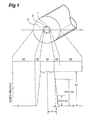
- Fig. 1 is a schematic diagram to show a cross-sectional structure and an index profile of an embodiment of the single-mode optical fiber.
- Fig. 2 is a graph to show change of zero dispersion wavelength against the change rate in relative index difference.
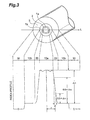
- Fig. 3 is a schematic diagram to show a cross-sectional structure and an index profile of another embodiment of the single-mode optical fiber.
- Fig. 1 is a diagram schematically showing a cross-sectional structure of an embodiment of a single-mode optical fiber according to the present invention and a refractive index profile thereof in the direction along the fiber diameter (or in the direction indicated by a line L in the figure).
- the horizontal axis of the index profile illustrated in Fig. 1 corresponds to positions on the cross section perpendicular to the center axis of core portion 1 along the line L indicated in the cross-sectional structure in the figure though it is drawn in different scale.
- a core region 10 corresponds to a region of a core portion 1 on the line L, an interfacial region 20 to a region of an interfacial portion 2 on the line L, and a cladding region 30 to a region of a cladding portion 3 on the line L, respectively.
- the vertical axis of the index profile represents relative index differences with respect to the refractive index of the cladding region 30.
- the refractive indices of the interfacial region 20 formed in the boundary between these two regions continuously change and decrease from the index n 1 to n 2 from the core region 10 side to the cladding region 30 side.
- an accurate and specific evaluation method e.g., a change range of relative index difference as a reference.
- the inventors conducted investigation, based on actual measurement results with various optical fibers, and set from the investigation the change range of relative index difference to be used for the evaluation, to the domain of change from 0.8 ⁇ ⁇ n to 0.3 ⁇ ⁇ n (the range of 80% to 30% if the relative index difference of the core region 10 is 100%).
- index change in the interfacial region 20 and selection of optical fiber based thereon is carried out for transparent glass base materials (preforms) of optical fibers, using an index profile measuring instrument (preform analyzer).
- preform analyzer index profile measuring instrument
- an index change of an optical fiber after drawing is calculated with correction by the equivalent step index method (ESI method) if necessary.
- an upper limit and a lower limit of an index change range used in the evaluation are determined with respect to the relative index difference ⁇ n of the core region 10 and a change rate determined for that change range is used as an index for the evaluation of refractive index change.
- a change rate determined for that change range is used as an index for the evaluation of refractive index change.
- the change range so as to best match the characteristics of various optical fibers used in practice and permit accurate evaluation of change rate. From the investigation based on the measurement results, the inventors selected and set the aforementioned change range of 80% to 30% as a favorable range for the evaluation and selection.
- the evaluation of change rate is conducted using the core radius r illustrated in Fig. 1, and the thickness d in the direction along the fiber diameter of the domain corresponding to the change range described above.
- the core radius r is defined by a radius at a position where the relative index difference is 1/e of ⁇ n. That position is a position where the relative index difference of the interfacial region 20 is about 0.37 ⁇ ⁇ n, and, therefore, the core radius r is different from the outside radius of the core region 10.
- the change rate is evaluated by a change rate in relative index difference obtained when the core radius r is 1, i.e., when it is normalized by the core radius, and that value is defined as (0.5 ⁇ ⁇ n)/(d/r).
- the change rate in relative index difference was determined from the thickness d between the position of the relative index difference of 0.8 ⁇ ⁇ n and the position of the relative index difference of 0.3 ⁇ ⁇ n and from the change of relative index difference of 0.5 ⁇ ⁇ n between the two positions, but it may be determined using other calculation methods.
- a plurality of index measurement points in the range from 0.8 ⁇ ⁇ n to 0.3 ⁇ ⁇ n are fitted to a straight line by an approximation method, e.g. the least square fitting or the like, and the equivalent thickness d and rate of relative index difference change are calculated from the slope of the straight line. It is, however, desirable to use the same calculation method of change rate for comparison among change rates in relative index difference obtained for respective optical fibers.
- the evaluation can be implemented if the core part is vitrified. It is common practice to use a process of first making the core part and the cladding part and thereafter adding an adequate jacket layer thereto to fabricate an optical fiber preform.
- the measurement of index profile of the preform may be done for the transparent glass preform either before or after the addition of the jacket layer.
- the index profile measurement can also be carried out in similar fashion.
- the characteristics of the optical fiber obtained by drawing this preform were the cutoff wavelength of 1262 nm, the mode field diameter of 9.28 ⁇ m, and the zero dispersion wavelength of 1316 nm, which were good characteristics for 1.3 ⁇ m-band phototransmission.
- the transmission losses at 1310 nm and at 1550 nm were 0.331 dB/km and 0.192 dB/km, respectively, and it was thus verified that there appeared no degradation of transmission losses and the low transmission losses were achieved in the above allowable range of the change rate in relative index difference.
- the characteristics were determined for a single-mode optical fiber having the change rate in relative index difference of not more than 0.4%, i.e., the change rate of 0.37% outside the above allowable range.
- the change rate is small as in this case, the influence of the tail spread becomes stronger on the phototransmission.
- the characteristics obtained were the cutoff wavelength of 1265 nm, the mode field diameter of 9.30 ⁇ m, and the zero dispersion wavelength of 1324 nm. This is a large shift to the long wavelength side and is not preferable for 1.3 ⁇ m-band phototransmission.
- Fig. 2 is a graph to show the variation of the zero dispersion wavelength ⁇ o against the change rate in relative index difference.
- the zero dispersion wavelength ⁇ s indicated by a dashed line represents the zero dispersion wavelength in the case where a perfect step shape is assumed.
- the zero dispersion wavelength ⁇ 0 of the single-mode optical fiber increases with decrease in values of the change rate in relative index difference. Therefore, the aforementioned lower limit 0.4% of the change rate in relative index difference is also effective in order to keep this zero dispersion wavelength in a favorable range.
- the fabrication method of fabricating the single-mode optical fiber in the above structure is preferably one having a forming step of forming the core region by the VAD method or the OVD method, and a selection step of selecting a transparent glass preform of the single-mode optical fiber including the core region.
- the evaluation by the change rate in relative index difference is carried out as described above for the transparent glass preform and the optical fiber is selected by applying the aforementioned preferable range of not less than 0.4% nor more than 4.0% or the more preferable range of not less than 2.0% nor more than 4.0%. This ensures fabrication of the low loss single-mode optical fiber.
- the temperature on the side face of the core part is increased to raise the change rate in relative index difference by either of methods of increasing the flow rate of combustion gas, adjusting positional relation between burners, and so on, whereby the change rate in relative index difference of the optical fiber obtained can be adjusted.
- Fig. 3 is a diagram schematically showing a cross-sectional structure of another embodiment of the single-mode optical fiber according to the present invention and an index profile thereof in the direction along the fiber diameter (or in the direction indicated by the line L in the figure).
- This optical fiber has an inner core portion 1a (inner core region 10a), an outer core portion 1b (outer core region 10b), and a cladding portion 3 (cladding region 30), and an interfacial portion 2 (interfacial region 20) is formed in the boundary between the inner core portion 1a (inner core region 10a) and the outer core portion 1b (outer core region 10b).
- n 1 is the refractive index of the inner core region 10a
- n 2 the refractive index of the outer core region 10b herein.
- the single-mode optical fiber having the inner core region 10a and the outer core region 10b in this index profile structure, it is also feasible to provide the single-mode optical fiber with favorable characteristics, by setting the allowable range similarly to the range of not less than 0.4% nor more than 4.0% or to the range of not less than 2.0% nor more than 4.0% for the change rate in relative index difference (0.5 ⁇ ⁇ n)/(d/r) defined from the relative index difference ⁇ n defined as described above, the inner core radius r defined for the inner core in a manner similar to the core radius in Fig. 1, and the thickness d between the position of the relative index difference of 0.8 ⁇ ⁇ n and the position of the relative index difference of 0.3 ⁇ ⁇ n.
- the above condition based on the change rate in relative index difference for the inner core region can also be applied similarly to single-mode optical fibers having the segment type core structure in which a ring core region of ring shape is formed outside a core region.
- the present invention can be applied to the single-mode optical fibers provided with the interfacial region having the favorable index change so as to implement low loss phototransmission, and to the fabrication methods to fabricate such single-mode optical fibers.
- the invention is advantageous in that when the optical fiber is selected by using the change rate in relative index difference obtained for the domain of relative index difference from 0.8 ⁇ ⁇ n to 0.3 ⁇ ⁇ n, as an index for the evaluation of refractive index change and setting the allowable range of values of the change rate to the range of not less than 0.4% nor more than 4.0%, the single-mode optical fiber with favorable characteristics and with low transmission loss can be realized while reducing the influence of the tail spread and the strain in the optical fiber.
Landscapes
- Physics & Mathematics (AREA)
- General Physics & Mathematics (AREA)
- Optics & Photonics (AREA)
- Manufacture, Treatment Of Glass Fibers (AREA)
Abstract
Description
Claims (6)
- A single-mode optical fiber comprising a core region having a refractive index of n1 and a cladding region disposed around the periphery of said core region and having a refractive index of n2 to satisfy n2 < n1,wherein a relative index difference in each part is determined with respect to the refractive index n2 of said cladding region, and a relative index difference of said core region is defined as Δn,wherein in an interfacial region with a continuously changing index profile near a boundary between said core region and said cladding region, for a domain in which a relative index difference varies from 0.8 × Δn to 0.3 × Δn, a change rate in relative index difference (0.5 × Δn)/(d/r) normalized by a core radius r, where d is a thickness of said domain in a direction along a fiber diameter, and 0.5 × Δn is a relative index difference change, is not less than 0.4% nor more than 4.0%.
- A single-mode optical fiber comprising an inner core region having a refractive index of n1, an outer core region disposed around the periphery of said inner core region and having a refractive index of n2 to satisfy n2 < n1, and a cladding region disposed around the periphery of said outer core region,wherein a relative index difference in each part is determined with respect to the refractive index n2 of said outer core region, and a relative index difference of said inner core region is defined as Δn,wherein in an interfacial region with a continuously changing index profile near a boundary between said inner core region and said outer core region, for a domain in which a relative index difference varies from 0.8 × Δn to 0.3 × Δn, a change rate in relative index difference (0.5 × Δn)/(d/r) normalized by an inner core radius r, where d is a thickness of said domain in a direction along a fiber diameter, and 0.5 × Δn is a relative index difference change, is not less than 0.4% nor more than 4.0%.
- A single-mode optical fiber according to Claim 1 or 2, wherein said change rate in relative index difference (0.5 × Δn)/(d/r) is not less than 2.0% nor more than 4.0%.
- A method of fabricating a single-mode optical fiber comprising a core region having a refractive index of n1 and a cladding region disposed around the periphery of said core region and having a refractive index of n2 to satisfy n2 < n1,
said method comprising:a forming step of forming said core region by a VAD method or an OVD method; anda selection step of selecting a transparent glass perform of the single-mode optical fiber including said core region,wherein in said selection step,a relative index difference in each part is determined with respect to the refractive index n2 of said cladding region, and a relative index difference of said core region is defined as Δn, andsaid transparent glass preform is selected so that in an interfacial region with a continuously changing index profile near a boundary between said core region and said cladding region, for a domain in which a relative index difference varies from 0.8 × Δn to 0.3 × Δn, a change rate in relative index difference (0.5 × Δn)/(d/r) normalized by a core radius r, where d is a thickness of said domain in a direction along a fiber diameter, and 0.5 × Δn is a relative index difference change, is not less than 0.4% nor more than 4.0%. - A method of fabricating a single-mode optical fiber comprising an inner core region having a refractive index of n1, an outer core region disposed around the periphery of said inner core region and having a refractive index of n2 to satisfy n2 < n1, and a cladding region disposed around the periphery of said outer core region,
said method comprising:a forming step of forming said inner core region by a VAD method or an OVD method; anda selection step of selecting a transparent glass preform of the single-mode optical fiber including said inner core region,wherein in said selection step,a relative index difference in each part is determined with respect to the refractive index n2 of said outer core region, and a relative index difference of said inner core region is defined as Δn, andsaid transparent glass preform is selected so that in an interfacial region with a continuously changing index profile near a boundary between said inner core region and said outer core region, for a domain in which a relative index difference varies from 0.8 × Δn to 0.3 × Δn, a change rate in relative index difference (0.5 × Δn)/(d/r) normalized by an inner core radius r, where d is a thickness of said domain in a direction along a fiber diameter, and 0.5 × Δn is a relative index difference change, is not less than 0.4% nor more than 4.0%. - A method of fabricating a single-mode optical fiber according to Claim 4 or 5, wherein said selection step comprises a step of selecting said transparent glass preform so that said change rate in relative index difference is not less than 2.0% nor more than 4.0%.
Applications Claiming Priority (3)
| Application Number | Priority Date | Filing Date | Title |
|---|---|---|---|
| JP31224098 | 1998-11-02 | ||
| JP31224098 | 1998-11-02 | ||
| PCT/JP1999/006040 WO2000026709A1 (en) | 1998-11-02 | 1999-10-29 | Single-mode optical fiber and its production method |
Publications (2)
| Publication Number | Publication Date |
|---|---|
| EP1136849A1 true EP1136849A1 (en) | 2001-09-26 |
| EP1136849A4 EP1136849A4 (en) | 2002-09-04 |
Family
ID=18026864
Family Applications (1)
| Application Number | Title | Priority Date | Filing Date |
|---|---|---|---|
| EP99951162A Withdrawn EP1136849A4 (en) | 1998-11-02 | 1999-10-29 | SINGLE-MODE OPTICAL FIBER AND PROCESS FOR PRODUCING THE SAME |
Country Status (6)
| Country | Link |
|---|---|
| US (1) | US6625360B2 (en) |
| EP (1) | EP1136849A4 (en) |
| KR (1) | KR100661766B1 (en) |
| CN (1) | CN1139823C (en) |
| AU (1) | AU768742B2 (en) |
| WO (1) | WO2000026709A1 (en) |
Cited By (2)
| Publication number | Priority date | Publication date | Assignee | Title |
|---|---|---|---|---|
| US7069748B2 (en) * | 2001-11-09 | 2006-07-04 | Fujikura, Ltd. | Optical fiber, optical fiber preform, and manufacturing method therefor |
| US7760771B2 (en) | 2004-08-26 | 2010-07-20 | Corelase Oy | Optical fiber gain medium with modal discrimination of amplification |
Families Citing this family (12)
| Publication number | Priority date | Publication date | Assignee | Title |
|---|---|---|---|---|
| NL1018338C2 (en) * | 2001-06-20 | 2002-12-30 | Draka Fibre Technology Bv | Optical fiber. |
| US7003203B2 (en) * | 2003-07-18 | 2006-02-21 | Corning Incorporated | Large effective area, low kappa, dispersion compensating optical fiber and telecommunication span including same |
| JP5408834B2 (en) * | 2003-10-03 | 2014-02-05 | ドラカ・コムテツク・ベー・ベー | Chromatic dispersion compensating optical fiber |
| JP2006154707A (en) * | 2004-10-29 | 2006-06-15 | Shin Etsu Chem Co Ltd | Optical fiber |
| CN1847179B (en) * | 2005-04-13 | 2010-09-08 | 富通集团有限公司 | A kind of optical fiber preform production method |
| JP4690956B2 (en) * | 2006-07-07 | 2011-06-01 | 古河電気工業株式会社 | Optical fiber preform manufacturing method |
| PT3084490T (en) * | 2013-12-20 | 2021-02-05 | Draka Comteq Bv | Single mode fibre with a trapezoid core, showing reduced losses |
| US10358376B2 (en) * | 2014-03-06 | 2019-07-23 | Brown University | Method and apparatus for creating coherent bundle of scintillating fibers |
| US10399887B2 (en) | 2014-03-06 | 2019-09-03 | Brown University | Method and apparatus for creating coherent bundle of scintillating fibers |
| PL3729151T3 (en) | 2017-12-21 | 2022-07-25 | Draka Comteq France | Bending-loss insensitive single mode fibre, with a shallow trench, and corresponding optical system |
| JP2021018337A (en) | 2019-07-22 | 2021-02-15 | 住友電気工業株式会社 | Single-mode optical fiber and single-mode optical fiber manufacturing method |
| CN113912280A (en) * | 2020-07-07 | 2022-01-11 | 信越化学工业株式会社 | Optical fiber preform |
Family Cites Families (23)
| Publication number | Priority date | Publication date | Assignee | Title |
|---|---|---|---|---|
| JPS5627843B2 (en) * | 1972-06-05 | 1981-06-27 | ||
| JPS5627843A (en) | 1979-08-15 | 1981-03-18 | Hitachi Ltd | Air volume control for air-conditioner |
| US4339174A (en) * | 1980-02-01 | 1982-07-13 | Corning Glass Works | High bandwidth optical waveguide |
| JPS6048456B2 (en) * | 1980-07-25 | 1985-10-28 | 日本電信電話株式会社 | Method for manufacturing base material for optical fiber |
| US4516826A (en) * | 1983-04-21 | 1985-05-14 | At&T Technologies, Inc. | Single mode lightguide fiber having a trapezoidal refractive index profile |
| JPS6048456A (en) | 1983-08-25 | 1985-03-16 | 松下電器産業株式会社 | Heat pump device |
| JPS6252508A (en) * | 1985-09-02 | 1987-03-07 | Nippon Telegr & Teleph Corp <Ntt> | Optical fiber |
| US4852968A (en) * | 1986-08-08 | 1989-08-01 | American Telephone And Telegraph Company, At&T Bell Laboratories | Optical fiber comprising a refractive index trench |
| JPH0764578B2 (en) * | 1987-12-11 | 1995-07-12 | 住友電気工業株式会社 | Manufacturing method of base material for single mode optical fiber |
| JPH0788231B2 (en) * | 1989-06-06 | 1995-09-27 | 信越化学工業株式会社 | Manufacturing method of optical fiber preform |
| DE4033768C1 (en) * | 1990-10-24 | 1991-07-18 | Schott Glaswerke, 6500 Mainz, De | Flexible optical fibre transmitting polychromatic beams - has refractive profile such that convergence angle at input and divergence angle at output are practically independent of wavelength |
| DE4127868C2 (en) * | 1991-08-22 | 1994-11-10 | Rheydt Kabelwerk Ag | Single-mode fiber with a ramp-shaped refractive index profile |
| JP2977966B2 (en) * | 1991-09-05 | 1999-11-15 | 古河電気工業株式会社 | Method for manufacturing single mode optical fiber preform |
| GB2273389B (en) * | 1992-12-14 | 1996-07-17 | Pirelli Cavi Spa | Rare earth doped optical fibre amplifiers |
| US5278931A (en) * | 1992-12-31 | 1994-01-11 | Corning Incorporated | Low bend loss singlemode optical waveguide fiber |
| KR950000588A (en) * | 1993-06-18 | 1995-01-03 | 쿠라우찌 노리타카 | Manufacturing method of single mode optical fiber base material |
| JP2965236B2 (en) * | 1993-12-28 | 1999-10-18 | 信越化学工業株式会社 | Manufacturing method of preform for optical fiber |
| JPH0788231A (en) | 1994-04-14 | 1995-04-04 | Sankyo Kk | Game machine |
| JP2996111B2 (en) * | 1994-11-11 | 1999-12-27 | 日立電線株式会社 | Optical fiber preform manufacturing method |
| BR9500990A (en) * | 1995-03-28 | 1995-08-01 | Abc Algar | Optical waveguide |
| JPH09263418A (en) * | 1996-03-28 | 1997-10-07 | Shin Etsu Chem Co Ltd | Method and apparatus for manufacturing porous preform for single-mode optical fiber |
| JPH10186156A (en) * | 1996-12-26 | 1998-07-14 | Furukawa Electric Co Ltd:The | Step-type dispersion-shifted optical fiber |
| JPH10274720A (en) * | 1997-01-29 | 1998-10-13 | Sumitomo Electric Ind Ltd | Single mode optical fiber |
-
1999
- 1999-10-29 WO PCT/JP1999/006040 patent/WO2000026709A1/en not_active Ceased
- 1999-10-29 KR KR1020017005284A patent/KR100661766B1/en not_active Expired - Lifetime
- 1999-10-29 AU AU63679/99A patent/AU768742B2/en not_active Ceased
- 1999-10-29 CN CNB998132705A patent/CN1139823C/en not_active Expired - Lifetime
- 1999-10-29 EP EP99951162A patent/EP1136849A4/en not_active Withdrawn
-
2001
- 2001-05-01 US US09/845,301 patent/US6625360B2/en not_active Expired - Lifetime
Cited By (2)
| Publication number | Priority date | Publication date | Assignee | Title |
|---|---|---|---|---|
| US7069748B2 (en) * | 2001-11-09 | 2006-07-04 | Fujikura, Ltd. | Optical fiber, optical fiber preform, and manufacturing method therefor |
| US7760771B2 (en) | 2004-08-26 | 2010-07-20 | Corelase Oy | Optical fiber gain medium with modal discrimination of amplification |
Also Published As
| Publication number | Publication date |
|---|---|
| KR20010089366A (en) | 2001-10-06 |
| US20020021877A1 (en) | 2002-02-21 |
| CN1139823C (en) | 2004-02-25 |
| KR100661766B1 (en) | 2006-12-28 |
| CN1326555A (en) | 2001-12-12 |
| AU768742B2 (en) | 2004-01-08 |
| EP1136849A4 (en) | 2002-09-04 |
| WO2000026709A1 (en) | 2000-05-11 |
| US6625360B2 (en) | 2003-09-23 |
| AU6367999A (en) | 2000-05-22 |
Similar Documents
| Publication | Publication Date | Title |
|---|---|---|
| US5740297A (en) | Dispersion-compensating fiber and method of fabricating the same | |
| JP3068013B2 (en) | Dispersion compensating fiber | |
| EP0260795B1 (en) | Optical fiber | |
| EP2299302B1 (en) | Multimode optical fibre having improved bending losses | |
| US6295843B1 (en) | Method of making a single-mode optical fiber with multiple concentric core portions by using an outside vapor deposition process | |
| US11579355B2 (en) | Low cross-talk multicore optical fiber for single mode operation | |
| US11531156B2 (en) | Multicore optical fiber with depressed index common cladding | |
| EP1136849A1 (en) | Single-mode optical fiber and its production method | |
| US6205279B1 (en) | Single mode optical fiber having multi-step core structure and method of fabricating the same | |
| CA1248386A (en) | Quadruple-clad optical fiberguide | |
| US5956448A (en) | Optical fiber waveguide | |
| EP3657223B1 (en) | Optical fiber and method for producing same | |
| US6603914B2 (en) | Dispersion compensating fiber with reduced splice loss and methods for making same | |
| US12535637B2 (en) | Uncoupled multicore optical fiber with alkali doped, off-set trench cores | |
| JPH1195049A (en) | Multicore optical fiber | |
| KR100255409B1 (en) | Method for the preparation of an optical fiber preform | |
| US6678451B2 (en) | Multimode optical fiber having a structure to reduce scattering loss | |
| JP2002522811A (en) | Dispersion-shifted single-mode optical fiber with central trough | |
| JPH08201639A (en) | Low dispersion optical fiber | |
| JPWO2000026709A1 (en) | Single-mode optical fiber and its manufacturing method |
Legal Events
| Date | Code | Title | Description |
|---|---|---|---|
| PUAI | Public reference made under article 153(3) epc to a published international application that has entered the european phase |
Free format text: ORIGINAL CODE: 0009012 |
|
| 17P | Request for examination filed |
Effective date: 20010531 |
|
| AK | Designated contracting states |
Kind code of ref document: A1 Designated state(s): AT BE CH CY DE DK ES FI FR GB GR IE IT LI LU MC NL PT SE |
|
| A4 | Supplementary search report drawn up and despatched |
Effective date: 20020718 |
|
| AK | Designated contracting states |
Kind code of ref document: A4 Designated state(s): DE FR GB IT |
|
| 17Q | First examination report despatched |
Effective date: 20020830 |
|
| RBV | Designated contracting states (corrected) |
Designated state(s): DE FR GB IT |
|
| STAA | Information on the status of an ep patent application or granted ep patent |
Free format text: STATUS: THE APPLICATION IS DEEMED TO BE WITHDRAWN |
|
| 18D | Application deemed to be withdrawn |
Effective date: 20050120 |