EP1136834A3 - Integrated circuit with a control circuit for controlling a driver circuit - Google Patents
Integrated circuit with a control circuit for controlling a driver circuit Download PDFInfo
- Publication number
- EP1136834A3 EP1136834A3 EP01104729A EP01104729A EP1136834A3 EP 1136834 A3 EP1136834 A3 EP 1136834A3 EP 01104729 A EP01104729 A EP 01104729A EP 01104729 A EP01104729 A EP 01104729A EP 1136834 A3 EP1136834 A3 EP 1136834A3
- Authority
- EP
- European Patent Office
- Prior art keywords
- circuit
- signal
- dqs
- output
- digital signal
- Prior art date
- Legal status (The legal status is an assumption and is not a legal conclusion. Google has not performed a legal analysis and makes no representation as to the accuracy of the status listed.)
- Withdrawn
Links
- 230000007704 transition Effects 0.000 abstract 3
Classifications
-
- G—PHYSICS
- G01—MEASURING; TESTING
- G01R—MEASURING ELECTRIC VARIABLES; MEASURING MAGNETIC VARIABLES
- G01R31/00—Arrangements for testing electric properties; Arrangements for locating electric faults; Arrangements for electrical testing characterised by what is being tested not provided for elsewhere
- G01R31/28—Testing of electronic circuits, e.g. by signal tracer
- G01R31/317—Testing of digital circuits
- G01R31/3181—Functional testing
- G01R31/3185—Reconfiguring for testing, e.g. LSSD, partitioning
-
- G—PHYSICS
- G01—MEASURING; TESTING
- G01R—MEASURING ELECTRIC VARIABLES; MEASURING MAGNETIC VARIABLES
- G01R31/00—Arrangements for testing electric properties; Arrangements for locating electric faults; Arrangements for electrical testing characterised by what is being tested not provided for elsewhere
- G01R31/28—Testing of electronic circuits, e.g. by signal tracer
- G01R31/317—Testing of digital circuits
- G01R31/31712—Input or output aspects
- G01R31/31715—Testing of input or output circuits; test of circuitry between the I/C pins and the functional core, e.g. testing of input or output driver, receiver, buffer
Landscapes
- Engineering & Computer Science (AREA)
- General Engineering & Computer Science (AREA)
- Physics & Mathematics (AREA)
- General Physics & Mathematics (AREA)
- Dram (AREA)
- Tests Of Electronic Circuits (AREA)
- For Increasing The Reliability Of Semiconductor Memories (AREA)
- Logic Circuits (AREA)
Abstract
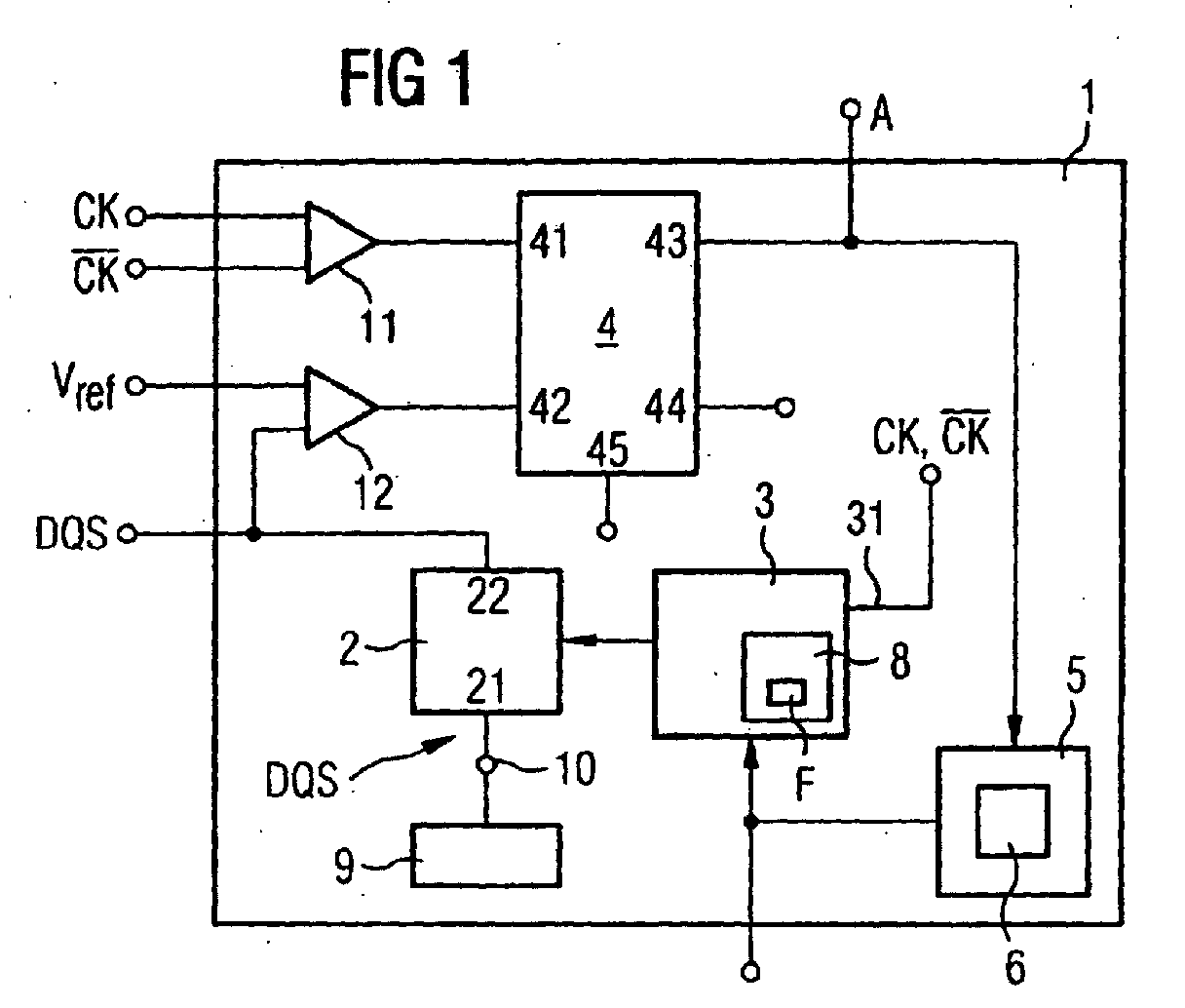
Eine integrierte Schaltung mit einem Anschluß (10) für ein
digitales Signal (DQS) weist eine steuerbare Treiberschaltung
(2) auf, an der das digitale Signal (DQS) anliegt, und die
zur Ausgabe des digitalen Signals (DQS) dient. Mittels einer
einstellbaren Ansteuerungsschaltung (3), die einen Eingang
(31) für ein Taktsignal (CK) aufweist, wird die Treiberschaltung
(2) in Abhängigkeit des Taktsignals (CK) angesteuert.
Die integrierte Schaltung enthält außerdem eine Vergleichseinrichtung
(4) zum zeitlichen Vergleich von Signalübergängen
des Taktsignals (CK) mit Signalübergängen des digitalen Signals
(DQS). Am Ausgang (43) der Vergleichseinrichtung (4)
ist ein Ausgangssignal (A) abgreifbar. So ist in einem Testbetrieb
ein zeitlicher Vergleich der Signalübergänge des
Taktsignals (CK) und des digitalen Signals (DQS) am Ausgang
der steuerbaren Treiberschaltung (2) mit einer vergleichsweise
hohen Genauigkeit durchführbar.
Applications Claiming Priority (2)
| Application Number | Priority Date | Filing Date | Title |
|---|---|---|---|
| DE10014386 | 2000-03-23 | ||
| DE10014386A DE10014386A1 (en) | 2000-03-23 | 2000-03-23 | Integrated circuit with control circuit for controlling a driver circuit |
Publications (2)
| Publication Number | Publication Date |
|---|---|
| EP1136834A2 EP1136834A2 (en) | 2001-09-26 |
| EP1136834A3 true EP1136834A3 (en) | 2005-01-19 |
Family
ID=7636018
Family Applications (1)
| Application Number | Title | Priority Date | Filing Date |
|---|---|---|---|
| EP01104729A Withdrawn EP1136834A3 (en) | 2000-03-23 | 2001-02-26 | Integrated circuit with a control circuit for controlling a driver circuit |
Country Status (4)
| Country | Link |
|---|---|
| US (1) | US6351161B2 (en) |
| EP (1) | EP1136834A3 (en) |
| DE (1) | DE10014386A1 (en) |
| TW (1) | TW525343B (en) |
Families Citing this family (4)
| Publication number | Priority date | Publication date | Assignee | Title |
|---|---|---|---|---|
| US7015300B2 (en) | 1995-06-07 | 2006-03-21 | Acushnet Company | Multilayered golf ball and composition |
| DE602006010915D1 (en) * | 2006-07-17 | 2010-01-14 | Infineon Technologies Ag | ONCHIP CHECK FOR AN EMBEDDED COMPARATOR |
| US20080080266A1 (en) * | 2006-09-27 | 2008-04-03 | Khellah Muhammad M | Memory driver circuits with embedded level shifters |
| US8624653B2 (en) | 2011-06-15 | 2014-01-07 | Freescale Semiconductor, Inc. | Circuit and method for determining comparator offsets of electronic devices |
Citations (4)
| Publication number | Priority date | Publication date | Assignee | Title |
|---|---|---|---|---|
| WO1997025664A1 (en) * | 1996-01-03 | 1997-07-17 | Credence Systems Corporation | Signal deskewing system for synchronous logic circuit |
| US5771264A (en) * | 1996-08-29 | 1998-06-23 | Altera Corporation | Digital delay lock loop for clock signal frequency multiplication |
| JPH11265573A (en) * | 1998-01-13 | 1999-09-28 | Mitsubishi Electric Corp | Semiconductor storage device |
| JP2000076853A (en) * | 1998-06-17 | 2000-03-14 | Mitsubishi Electric Corp | Synchronous semiconductor memory device |
Family Cites Families (9)
| Publication number | Priority date | Publication date | Assignee | Title |
|---|---|---|---|---|
| DE102027C (en) | ||||
| DD102027A1 (en) * | 1972-12-18 | 1973-11-20 | ||
| US4799023A (en) * | 1981-11-05 | 1989-01-17 | Hewlett-Packard Company | Circuits and apparatus which enable elimination of setup time and hold time testing errors |
| US5471159A (en) * | 1992-09-18 | 1995-11-28 | Tektronix, Inc. | Setup or hold violation triggering |
| US5959481A (en) * | 1997-02-18 | 1999-09-28 | Rambus Inc. | Bus driver circuit including a slew rate indicator circuit having a one shot circuit |
| GB9800925D0 (en) * | 1998-01-17 | 1998-03-11 | Lucas Ind Plc | Power switching circuit for use in a power distribution system |
| JPH11306757A (en) * | 1998-04-27 | 1999-11-05 | Mitsubishi Electric Corp | Synchronous semiconductor memory device |
| US6100733A (en) * | 1998-06-09 | 2000-08-08 | Siemens Aktiengesellschaft | Clock latency compensation circuit for DDR timing |
| US6232801B1 (en) * | 1999-08-04 | 2001-05-15 | Vlsi Technology, Inc. | Comparators and comparison methods |
-
2000
- 2000-03-23 DE DE10014386A patent/DE10014386A1/en not_active Ceased
-
2001
- 2001-02-26 EP EP01104729A patent/EP1136834A3/en not_active Withdrawn
- 2001-03-22 TW TW090106784A patent/TW525343B/en not_active IP Right Cessation
- 2001-03-23 US US09/816,935 patent/US6351161B2/en not_active Expired - Lifetime
Patent Citations (5)
| Publication number | Priority date | Publication date | Assignee | Title |
|---|---|---|---|---|
| WO1997025664A1 (en) * | 1996-01-03 | 1997-07-17 | Credence Systems Corporation | Signal deskewing system for synchronous logic circuit |
| US5771264A (en) * | 1996-08-29 | 1998-06-23 | Altera Corporation | Digital delay lock loop for clock signal frequency multiplication |
| JPH11265573A (en) * | 1998-01-13 | 1999-09-28 | Mitsubishi Electric Corp | Semiconductor storage device |
| JP2000076853A (en) * | 1998-06-17 | 2000-03-14 | Mitsubishi Electric Corp | Synchronous semiconductor memory device |
| US6324118B1 (en) * | 1998-06-17 | 2001-11-27 | Mitsubishi Denki Kabushiki Kaisha | Synchronous semiconductor memory device having improved operational frequency margin at data input/output |
Non-Patent Citations (1)
| Title |
|---|
| PATENT ABSTRACTS OF JAPAN vol. 1999, no. 14 22 December 1999 (1999-12-22) * |
Also Published As
| Publication number | Publication date |
|---|---|
| DE10014386A1 (en) | 2001-09-27 |
| EP1136834A2 (en) | 2001-09-26 |
| US20010026173A1 (en) | 2001-10-04 |
| TW525343B (en) | 2003-03-21 |
| US6351161B2 (en) | 2002-02-26 |
Similar Documents
| Publication | Publication Date | Title |
|---|---|---|
| US4710704A (en) | IC test equipment | |
| EP1193677A3 (en) | Driving method for electro-optical device, electro-optical device, and electronic apparatus | |
| EP2511940A3 (en) | Method for operating a plasma supply device and plasma supply device | |
| KR20100019014A (en) | Method for data driving a display panel, data deriving circuit for performing the method and desplay device having the same | |
| EP1136834A3 (en) | Integrated circuit with a control circuit for controlling a driver circuit | |
| JPS5926999B2 (en) | Multi-point measuring device | |
| CN213372084U (en) | A Dental X-ray Detector Using Partial Signals to Realize Dual Mode Driving | |
| EP1482154A3 (en) | Circuit and method for controlling at least one electrical component of a motor vehicle | |
| CN206757019U (en) | Magnetic declination dipmeter automatic range switching circuit | |
| US3971204A (en) | Circuit for driving a DC motor for a clock | |
| DE2143090C3 (en) | Method for determining whether one or more setpoint values of electrical measured variables have been exceeded or fallen below, and a device for carrying out this method | |
| JPS60263995A (en) | LCD drive circuit | |
| CN118942415B (en) | A drive control circuit, a display device, and a drive control method. | |
| DE10344852A1 (en) | A wired interface arrangement and a method of operating a wired interface arrangement between a host and a device | |
| CN201444392U (en) | LCD Adjustment Device | |
| JPH1056657A5 (en) | ||
| JPH0317351Y2 (en) | ||
| DE2621116A1 (en) | Electronic control for windscreen wiper and washer - uses digital input for intermittent wipes and has wipe resistance monitor | |
| JPH062343Y2 (en) | Waveform shaping circuit for frequency measurement | |
| SU1670365A2 (en) | Method of measuring linear displacements and device thereof | |
| EP1087511A3 (en) | DC-DC converter | |
| JPS62141226U (en) | ||
| SU664287A1 (en) | Signal extremum detecting device | |
| KR910005334Y1 (en) | Vertical size adjustment circuit in PGA mode of color monitor | |
| JPS6381698A (en) | Sample/hold circuit |
Legal Events
| Date | Code | Title | Description |
|---|---|---|---|
| PUAI | Public reference made under article 153(3) epc to a published international application that has entered the european phase |
Free format text: ORIGINAL CODE: 0009012 |
|
| AK | Designated contracting states |
Kind code of ref document: A2 Designated state(s): AT BE CH CY DE DK ES FI FR GB GR IE IT LI LU MC NL PT SE TR |
|
| AX | Request for extension of the european patent |
Free format text: AL;LT;LV;MK;RO;SI |
|
| RIC1 | Information provided on ipc code assigned before grant |
Ipc: 7G 11C 7/22 B Ipc: 7G 11C 7/10 B Ipc: 7G 11C 29/00 B Ipc: 7G 01R 31/3185 A |
|
| PUAL | Search report despatched |
Free format text: ORIGINAL CODE: 0009013 |
|
| AK | Designated contracting states |
Kind code of ref document: A3 Designated state(s): AT BE CH CY DE DK ES FI FR GB GR IE IT LI LU MC NL PT SE TR |
|
| AX | Request for extension of the european patent |
Extension state: AL LT LV MK RO SI |
|
| 17P | Request for examination filed |
Effective date: 20050617 |
|
| AKX | Designation fees paid |
Designated state(s): DE GB IE |
|
| 17Q | First examination report despatched |
Effective date: 20070504 |
|
| STAA | Information on the status of an ep patent application or granted ep patent |
Free format text: STATUS: THE APPLICATION IS DEEMED TO BE WITHDRAWN |
|
| 18D | Application deemed to be withdrawn |
Effective date: 20090901 |