EP1136830A1 - Capteur de fréquence pour signaux numériques et procédé de surveillance de la fréquence d'un signal numérique - Google Patents
Capteur de fréquence pour signaux numériques et procédé de surveillance de la fréquence d'un signal numérique Download PDFInfo
- Publication number
- EP1136830A1 EP1136830A1 EP00106268A EP00106268A EP1136830A1 EP 1136830 A1 EP1136830 A1 EP 1136830A1 EP 00106268 A EP00106268 A EP 00106268A EP 00106268 A EP00106268 A EP 00106268A EP 1136830 A1 EP1136830 A1 EP 1136830A1
- Authority
- EP
- European Patent Office
- Prior art keywords
- frequency
- int
- counter
- clk
- clock signal
- Prior art date
- Legal status (The legal status is an assumption and is not a legal conclusion. Google has not performed a legal analysis and makes no representation as to the accuracy of the status listed.)
- Withdrawn
Links
Images

Classifications
-
- G—PHYSICS
- G01—MEASURING; TESTING
- G01R—MEASURING ELECTRIC VARIABLES; MEASURING MAGNETIC VARIABLES
- G01R23/00—Arrangements for measuring frequencies; Arrangements for analysing frequency spectra
- G01R23/02—Arrangements for measuring frequency, e.g. pulse repetition rate; Arrangements for measuring period of current or voltage
- G01R23/10—Arrangements for measuring frequency, e.g. pulse repetition rate; Arrangements for measuring period of current or voltage by converting frequency into a train of pulses, which are then counted, i.e. converting the signal into a square wave
-
- G—PHYSICS
- G01—MEASURING; TESTING
- G01R—MEASURING ELECTRIC VARIABLES; MEASURING MAGNETIC VARIABLES
- G01R23/00—Arrangements for measuring frequencies; Arrangements for analysing frequency spectra
- G01R23/02—Arrangements for measuring frequency, e.g. pulse repetition rate; Arrangements for measuring period of current or voltage
- G01R23/15—Indicating that frequency of pulses is either above or below a predetermined value or within or outside a predetermined range of values, by making use of non-linear or digital elements (indicating that pulse width is above or below a certain limit)
Definitions
- the invention relates to a frequency sensor for digital signals, which evaluates whether the frequency of an input signal larger or smaller than an allowed frequency range is.
- the invention also relates to a method for frequency monitoring of a digital signal.
- Periodic digital signals for example a clock signal for an electronic circuit, often have to be monitored to determine whether they are in a predetermined frequency range.
- the permitted frequency lies between a lower limit value F min and an upper frequency value F max .
- Frequency sensors are usually constructed as analog circuits.
- the limit values F min and F max therefore depend heavily on the manufacturing tolerances of the circuits.
- the object of the present invention is therefore a frequency sensor for digital signals, the simple one Possibility of programming provides.
- a procedure for frequency monitoring can be specified.
- a frequency sensor for digital Signals with an edge detector the input of which a connection for a filter input signal with two possible Level connected, a counter that has inputs for one Clock signal and a reset signal has one of three states having state memory, which with the counter and the Output of the edge detector is connected, being through the States of the state memory output signals of the filter sensor are determined, the state memory when reached a first definable value, which in conjunction with the Period of the clock signal describes a maximum pulse duration, a falling below an allowed frequency range occupies the marked state, with increasing / falling Edge of the input signal and a counter reading, which is below a second definable value, the one in connection with the period of the clock signal minimum pulse duration describes an exceeding of the permissible frequency range marking state and in other cases in neutral condition, and a reset signal on a rising / falling edge applied to the meter.
- the solution to the second part of the task is a procedure for frequency monitoring of a digital signal in one Counter variable on a rising edge of an input signal is set to a start value and then the counting variable step by step through a predetermined clock signal is increased / decreased when a first is reached definable value of the counter variable a first output variable too low a frequency of the input signal marking value is set, with an increasing Edge of the input signal the first or a second output variable too high a frequency of the input signal marking value is set if the counter variable is less than a second definable value, the second definable value smaller than the first definable Is worth.
- the definition of the limit values of an allowed frequency range happens by setting the first and second definable value. Another setting option, the Both limit values changed, the change in the frequency of the Clock signals. Apart from the definable values and the The frequency sensor according to the invention is completely clock frequency regardless of the component values of the individual elements.
- the invention Procedure is both for very low frequencies as well as applicable for very large frequencies.
- the frequency sensor can be done in a variety of ways without changing the structure Use cases are used.
- T min and T max of the input signal IN the time between two rising or falling edges can be used.
- the period T int_clk of an internal clock signal int_clk is used to determine the period.
- the period T min corresponds approximately to nL * T int_clk .
- T max ⁇ n H * T int_clk applies accordingly .
- the frequency of the internal clock signal int_clk is essential higher than that of the IN input signal being examined becomes.
- T int_clk 10 ns results for the period of the clock signal.
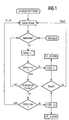
- a counting variable is reset on a rising edge of the input signal IN.
- the counting variable is increased by 1 on a rising edge of the clock signal int_clk.
- the counter variable is then checked to determine whether it has reached the value n L. If this is not the case and a rising edge has not been detected, counting continues on an edge of the clock signal int_clk. If the counter variable reaches the value n L , this means that the period of the input signal is longer than T min .
- the frequency is thus less than F min and a first output signal LF_Alarm is output.
- the counter variable is checked to see whether its value is less than or equal to n H. If this is not the case, the frequency of the input signal is in the permissible range and the counter is reset because a rising edge has been detected. However, if the counter variable is less than n H , the period of the input signal IN is too short and a second output signal HF_Alarm is output. The process can start again from the beginning with a reset signal.
- Figure 2 shows the associated state diagram.
- State “0” marks the normal state if the frequency is within the permissible range.
- Condition B is met if the count variable is less than n H , if a rising edge has been detected. State 1 H indicates that the frequency of the input signal is too high.
- a reset counter returns to the normal state "0".
- Condition C is fulfilled if the counter variable is less than n L and the counter variable is greater than n H when a rising edge occurs. If no rising edge was detected, it is sufficient if the counter variable is less than n L.
- FIG. 3 A block diagram of a circuit arrangement according to the invention, a frequency sensor, is shown in FIG. 3.
- An internal clock signal int clk affects both Counter BC, which is designed as an n-bit counter, and on one State memory FSM.
- the input signal IN affects one Edge detector ED, which detects a rising Edge gives a signal to the state memory FSM.
- a reset signal sets the edge detector ED and the state memory FSM back. This in turn acts via a corresponding one Signal int_rst to counter BC to reset the counter.
- the current status of the counter becomes the status memory Handed over to FSM.
- the states of the state memory FSM are displayed in the form of two output signals, namely by the LF_Alarm and the HF_Alarm signal.
- the logic the arrangement can be designed so that the frequency sensor only starts measuring again when a reset signal given to the corresponding input of the frequency sensor becomes, or begins after a certain period of time the arrangement again monitor the frequency by automatically a reset signal is generated.
- a third option is to reset the alarm indicator as soon as in a continuous measurement it was found that the Frequency is again in the permissible range.
- the edition the signals LF_Alarm and HF_Alarm would have a purely indicating Effect.
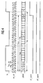
- FIG. 4 shows the signal profiles of the signals of the arrangement from FIG. 3.
- the frequency of the input signal IN is too low, that is, the period T IN is too large.
- the counter is reset to zero with the rising edge of the input signal IN. With the clock signal int_clk, the counter variable is counted until it reaches the value n L. Since no further rising edge has yet been detected and the counter has not been reset, the state memory changes to state 1 L and the output signal LF_Alarm assumes the HIGH level.
Landscapes
- Physics & Mathematics (AREA)
- General Physics & Mathematics (AREA)
- Nonlinear Science (AREA)
- Measuring Frequencies, Analyzing Spectra (AREA)
- Manipulation Of Pulses (AREA)
Priority Applications (2)
| Application Number | Priority Date | Filing Date | Title |
|---|---|---|---|
| EP00106268A EP1136830A1 (fr) | 2000-03-22 | 2000-03-22 | Capteur de fréquence pour signaux numériques et procédé de surveillance de la fréquence d'un signal numérique |
| PCT/DE2001/001087 WO2001071368A1 (fr) | 2000-03-22 | 2001-03-21 | Capteur de frequence pour signaux numeriques et procede de surveillance de la frequence d'un signal numerique |
Applications Claiming Priority (1)
| Application Number | Priority Date | Filing Date | Title |
|---|---|---|---|
| EP00106268A EP1136830A1 (fr) | 2000-03-22 | 2000-03-22 | Capteur de fréquence pour signaux numériques et procédé de surveillance de la fréquence d'un signal numérique |
Publications (1)
| Publication Number | Publication Date |
|---|---|
| EP1136830A1 true EP1136830A1 (fr) | 2001-09-26 |
Family
ID=8168206
Family Applications (1)
| Application Number | Title | Priority Date | Filing Date |
|---|---|---|---|
| EP00106268A Withdrawn EP1136830A1 (fr) | 2000-03-22 | 2000-03-22 | Capteur de fréquence pour signaux numériques et procédé de surveillance de la fréquence d'un signal numérique |
Country Status (2)
| Country | Link |
|---|---|
| EP (1) | EP1136830A1 (fr) |
| WO (1) | WO2001071368A1 (fr) |
Cited By (1)
| Publication number | Priority date | Publication date | Assignee | Title |
|---|---|---|---|---|
| US7504865B2 (en) | 2004-03-09 | 2009-03-17 | Panasonic Corporation | Frequency sensor and semiconductor device |
Citations (5)
| Publication number | Priority date | Publication date | Assignee | Title |
|---|---|---|---|---|
| US4137496A (en) * | 1977-09-16 | 1979-01-30 | Lind Leroy R | Line frequency deviation monitor |
| US4486752A (en) * | 1982-03-29 | 1984-12-04 | Rockwell International Corporation | Pulse width discriminator applicable to ATC transponders |
| DE3713802A1 (de) * | 1986-04-25 | 1987-11-05 | Mitsubishi Electric Corp | Detektorschaltung zur feststellung einer frequenzabweichung vom normalen wert |
| EP0403396A1 (fr) * | 1989-06-16 | 1990-12-19 | Jaeger | Dispositif de surveillance du fonctionnement d'un microcontrôleur ou microprocesseur |
| EP0788227A2 (fr) * | 1996-02-05 | 1997-08-06 | Mitsubishi Electric Semiconductor Software Co., Ltd. | Commutateur de temps |
-
2000
- 2000-03-22 EP EP00106268A patent/EP1136830A1/fr not_active Withdrawn
-
2001
- 2001-03-21 WO PCT/DE2001/001087 patent/WO2001071368A1/fr not_active Ceased
Patent Citations (5)
| Publication number | Priority date | Publication date | Assignee | Title |
|---|---|---|---|---|
| US4137496A (en) * | 1977-09-16 | 1979-01-30 | Lind Leroy R | Line frequency deviation monitor |
| US4486752A (en) * | 1982-03-29 | 1984-12-04 | Rockwell International Corporation | Pulse width discriminator applicable to ATC transponders |
| DE3713802A1 (de) * | 1986-04-25 | 1987-11-05 | Mitsubishi Electric Corp | Detektorschaltung zur feststellung einer frequenzabweichung vom normalen wert |
| EP0403396A1 (fr) * | 1989-06-16 | 1990-12-19 | Jaeger | Dispositif de surveillance du fonctionnement d'un microcontrôleur ou microprocesseur |
| EP0788227A2 (fr) * | 1996-02-05 | 1997-08-06 | Mitsubishi Electric Semiconductor Software Co., Ltd. | Commutateur de temps |
Non-Patent Citations (1)
| Title |
|---|
| J.SKINNER: "Digital frequency window", ELECTRONIC ENGINEERING, vol. 60, no. 739, July 1988 (1988-07-01), GB, pages 27, XP002147205 * |
Cited By (1)
| Publication number | Priority date | Publication date | Assignee | Title |
|---|---|---|---|---|
| US7504865B2 (en) | 2004-03-09 | 2009-03-17 | Panasonic Corporation | Frequency sensor and semiconductor device |
Also Published As
| Publication number | Publication date |
|---|---|
| WO2001071368A1 (fr) | 2001-09-27 |
Similar Documents
| Publication | Publication Date | Title |
|---|---|---|
| DE60026962T2 (de) | Einstellbarer Detektor für harmonische Verzerrungen und Verfahren mit Hilfe dieses Detektors | |
| DE2948330C2 (de) | Verfahren und Vorrichtung zur Frequenzmessung | |
| DE2727201A1 (de) | Beruehrungssteuertastenschaltung | |
| DE102008039195A1 (de) | Verfahren zum Erfassen der Frequenz eines Eingangstaktsignals einer integrierten Schaltung und integrierte Schaltung | |
| DE112009003680T5 (de) | Verfahren zum Ermitteln der Frequenz oder Periode eines Signals | |
| EP0017251B1 (fr) | Dispositif de commutation pour déterminer la durée moyenne de la période d'un signal périodique | |
| DE102008059791A1 (de) | Automatisch-mittelnde RC-Zeitkonstanten-Kalibrierung | |
| DE102006055844A1 (de) | Kapazitiver Sensor für eine physikalische Grösse, sowie Verfahren zu dessen Diagnose | |
| DE68913243T2 (de) | Phasendetektor zum schrittweisen Ermitteln einer Phasenbeziehung. | |
| EP0231786B1 (fr) | Procédé pour éliminer des perturbations dans un signal de mesure | |
| EP1494038B1 (fr) | Procédé et dispositif pour la détermination de la relation entre la constante de temps RC d'un circuit intégré et une valeur de consigne | |
| DE102005024648A1 (de) | Elektrische Schaltung zum Messen von Zeiten und Verfahren zum Messen von Zeiten | |
| DE4211701A1 (de) | Verfahren und Vorrichtung zur Phasenmessung | |
| DE102006041827B4 (de) | Verfahren zur Bestimmung eines Zeitintervalls | |
| EP1136830A1 (fr) | Capteur de fréquence pour signaux numériques et procédé de surveillance de la fréquence d'un signal numérique | |
| DE69028326T2 (de) | Signal-Pegel-Erkennungsschaltkreise | |
| DE69616267T2 (de) | Zeitschalter | |
| DE10319899B4 (de) | Verfahren und Frequenzvergleichseinrichtung zum Erzeugen eines Kontrollsignals, das eine Frequenzabweichung anzeigt | |
| DE2142711C3 (de) | Signalprüfschaltung für Signale, für welche bestimmte Toleranzbereiche vorgegeben sind | |
| DE60033112T2 (de) | Vorrichtung zur Messung der Zeitdauer eines Synchronisierungssignals und Anzeigevorrichtung | |
| DE3340455A1 (de) | Schaltungsanordnung zur auszaehlung von pulslaengen | |
| DE2722981B2 (de) | Digitales Filter für binäre Signale | |
| DE2712847C3 (de) | Sprachgeschützter frequenzselektiver Zeichenempfänger | |
| EP0706054B1 (fr) | Comparateur de phase | |
| AT397591B (de) | Messgerät zur erfassung und anzeige verschiedener messwerte, insbesondere zur messwerterfassung in netzwerken von wählsystemen |
Legal Events
| Date | Code | Title | Description |
|---|---|---|---|
| PUAI | Public reference made under article 153(3) epc to a published international application that has entered the european phase |
Free format text: ORIGINAL CODE: 0009012 |
|
| AK | Designated contracting states |
Kind code of ref document: A1 Designated state(s): AT BE CH CY DE DK ES FI FR GB GR IE IT LI LU MC NL PT SE |
|
| AX | Request for extension of the european patent |
Free format text: AL;LT;LV;MK;RO;SI |
|
| AKX | Designation fees paid | ||
| REG | Reference to a national code |
Ref country code: DE Ref legal event code: 8566 |
|
| STAA | Information on the status of an ep patent application or granted ep patent |
Free format text: STATUS: THE APPLICATION IS DEEMED TO BE WITHDRAWN |
|
| 18D | Application deemed to be withdrawn |
Effective date: 20020327 |