EP1136830A1 - Frequency sensing device for digital signals and method for monitoring the frequency of a digital signal - Google Patents
Frequency sensing device for digital signals and method for monitoring the frequency of a digital signal Download PDFInfo
- Publication number
- EP1136830A1 EP1136830A1 EP00106268A EP00106268A EP1136830A1 EP 1136830 A1 EP1136830 A1 EP 1136830A1 EP 00106268 A EP00106268 A EP 00106268A EP 00106268 A EP00106268 A EP 00106268A EP 1136830 A1 EP1136830 A1 EP 1136830A1
- Authority
- EP
- European Patent Office
- Prior art keywords
- frequency
- int
- counter
- clk
- clock signal
- Prior art date
- Legal status (The legal status is an assumption and is not a legal conclusion. Google has not performed a legal analysis and makes no representation as to the accuracy of the status listed.)
- Withdrawn
Links
Images

Classifications
-
- G—PHYSICS
- G01—MEASURING; TESTING
- G01R—MEASURING ELECTRIC VARIABLES; MEASURING MAGNETIC VARIABLES
- G01R23/00—Arrangements for measuring frequencies; Arrangements for analysing frequency spectra
- G01R23/02—Arrangements for measuring frequency, e.g. pulse repetition rate; Arrangements for measuring period of current or voltage
- G01R23/10—Arrangements for measuring frequency, e.g. pulse repetition rate; Arrangements for measuring period of current or voltage by converting frequency into a train of pulses, which are then counted, i.e. converting the signal into a square wave
-
- G—PHYSICS
- G01—MEASURING; TESTING
- G01R—MEASURING ELECTRIC VARIABLES; MEASURING MAGNETIC VARIABLES
- G01R23/00—Arrangements for measuring frequencies; Arrangements for analysing frequency spectra
- G01R23/02—Arrangements for measuring frequency, e.g. pulse repetition rate; Arrangements for measuring period of current or voltage
- G01R23/15—Indicating that frequency of pulses is either above or below a predetermined value or within or outside a predetermined range of values, by making use of non-linear or digital elements (indicating that pulse width is above or below a certain limit)
Definitions
- the invention relates to a frequency sensor for digital signals, which evaluates whether the frequency of an input signal larger or smaller than an allowed frequency range is.
- the invention also relates to a method for frequency monitoring of a digital signal.
- Periodic digital signals for example a clock signal for an electronic circuit, often have to be monitored to determine whether they are in a predetermined frequency range.
- the permitted frequency lies between a lower limit value F min and an upper frequency value F max .
- Frequency sensors are usually constructed as analog circuits.
- the limit values F min and F max therefore depend heavily on the manufacturing tolerances of the circuits.
- the object of the present invention is therefore a frequency sensor for digital signals, the simple one Possibility of programming provides.
- a procedure for frequency monitoring can be specified.
- a frequency sensor for digital Signals with an edge detector the input of which a connection for a filter input signal with two possible Level connected, a counter that has inputs for one Clock signal and a reset signal has one of three states having state memory, which with the counter and the Output of the edge detector is connected, being through the States of the state memory output signals of the filter sensor are determined, the state memory when reached a first definable value, which in conjunction with the Period of the clock signal describes a maximum pulse duration, a falling below an allowed frequency range occupies the marked state, with increasing / falling Edge of the input signal and a counter reading, which is below a second definable value, the one in connection with the period of the clock signal minimum pulse duration describes an exceeding of the permissible frequency range marking state and in other cases in neutral condition, and a reset signal on a rising / falling edge applied to the meter.
- the solution to the second part of the task is a procedure for frequency monitoring of a digital signal in one Counter variable on a rising edge of an input signal is set to a start value and then the counting variable step by step through a predetermined clock signal is increased / decreased when a first is reached definable value of the counter variable a first output variable too low a frequency of the input signal marking value is set, with an increasing Edge of the input signal the first or a second output variable too high a frequency of the input signal marking value is set if the counter variable is less than a second definable value, the second definable value smaller than the first definable Is worth.
- the definition of the limit values of an allowed frequency range happens by setting the first and second definable value. Another setting option, the Both limit values changed, the change in the frequency of the Clock signals. Apart from the definable values and the The frequency sensor according to the invention is completely clock frequency regardless of the component values of the individual elements.
- the invention Procedure is both for very low frequencies as well as applicable for very large frequencies.
- the frequency sensor can be done in a variety of ways without changing the structure Use cases are used.
- T min and T max of the input signal IN the time between two rising or falling edges can be used.
- the period T int_clk of an internal clock signal int_clk is used to determine the period.
- the period T min corresponds approximately to nL * T int_clk .
- T max ⁇ n H * T int_clk applies accordingly .
- the frequency of the internal clock signal int_clk is essential higher than that of the IN input signal being examined becomes.
- T int_clk 10 ns results for the period of the clock signal.
- a counting variable is reset on a rising edge of the input signal IN.
- the counting variable is increased by 1 on a rising edge of the clock signal int_clk.
- the counter variable is then checked to determine whether it has reached the value n L. If this is not the case and a rising edge has not been detected, counting continues on an edge of the clock signal int_clk. If the counter variable reaches the value n L , this means that the period of the input signal is longer than T min .
- the frequency is thus less than F min and a first output signal LF_Alarm is output.
- the counter variable is checked to see whether its value is less than or equal to n H. If this is not the case, the frequency of the input signal is in the permissible range and the counter is reset because a rising edge has been detected. However, if the counter variable is less than n H , the period of the input signal IN is too short and a second output signal HF_Alarm is output. The process can start again from the beginning with a reset signal.
- Figure 2 shows the associated state diagram.
- State “0” marks the normal state if the frequency is within the permissible range.
- Condition B is met if the count variable is less than n H , if a rising edge has been detected. State 1 H indicates that the frequency of the input signal is too high.
- a reset counter returns to the normal state "0".
- Condition C is fulfilled if the counter variable is less than n L and the counter variable is greater than n H when a rising edge occurs. If no rising edge was detected, it is sufficient if the counter variable is less than n L.
- FIG. 3 A block diagram of a circuit arrangement according to the invention, a frequency sensor, is shown in FIG. 3.
- An internal clock signal int clk affects both Counter BC, which is designed as an n-bit counter, and on one State memory FSM.
- the input signal IN affects one Edge detector ED, which detects a rising Edge gives a signal to the state memory FSM.
- a reset signal sets the edge detector ED and the state memory FSM back. This in turn acts via a corresponding one Signal int_rst to counter BC to reset the counter.
- the current status of the counter becomes the status memory Handed over to FSM.
- the states of the state memory FSM are displayed in the form of two output signals, namely by the LF_Alarm and the HF_Alarm signal.
- the logic the arrangement can be designed so that the frequency sensor only starts measuring again when a reset signal given to the corresponding input of the frequency sensor becomes, or begins after a certain period of time the arrangement again monitor the frequency by automatically a reset signal is generated.
- a third option is to reset the alarm indicator as soon as in a continuous measurement it was found that the Frequency is again in the permissible range.
- the edition the signals LF_Alarm and HF_Alarm would have a purely indicating Effect.
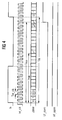
- FIG. 4 shows the signal profiles of the signals of the arrangement from FIG. 3.
- the frequency of the input signal IN is too low, that is, the period T IN is too large.
- the counter is reset to zero with the rising edge of the input signal IN. With the clock signal int_clk, the counter variable is counted until it reaches the value n L. Since no further rising edge has yet been detected and the counter has not been reset, the state memory changes to state 1 L and the output signal LF_Alarm assumes the HIGH level.
Landscapes
- Physics & Mathematics (AREA)
- General Physics & Mathematics (AREA)
- Nonlinear Science (AREA)
- Measuring Frequencies, Analyzing Spectra (AREA)
- Manipulation Of Pulses (AREA)
Abstract
Description
Frequenzsensor für digitale Signale und Verfahren zur Frequenzüberwachung eines digitalen SignalesFrequency sensor for digital signals and method for frequency monitoring of a digital signal
Die Erfindung betrifft einen Frequenzsensor für digitale Signale, der ausgewertet, ob die Frequenz eines Eingangssignales größer oder kleiner als ein erlaubter Frequenzbereich ist. Außerdem betrifft die Erfindung ein Verfahren zur Frequenzüberwachung eines digitalen Signales.The invention relates to a frequency sensor for digital signals, which evaluates whether the frequency of an input signal larger or smaller than an allowed frequency range is. The invention also relates to a method for frequency monitoring of a digital signal.
Häufig müssen periodische digitale Signale, beispielsweise ein Taktsignal für eine elektronische Schaltung, dahingehend überwacht werden, ob sie in einem vorgegebenen Frequenzbereich liegen. Die erlaubte Frequenz liegt dabei zwischen einem unteren Grenzwert Fmin und einem oberen Frequenzwert Fmax. Üblicherweise sind Frequenzsensoren als analoge Schaltungen aufgebaut. Die Grenzwerte Fmin und Fmax hängen daher stark von den Herstellungstoleranzen der Schaltkreise ab. Außerdem ist es oft gewünscht, die Grenzwerte je nach Anwendungsfall einstellen zu können, ohne dabei Änderungen an der Schaltungsanordnung bzw. dem Chipdesign vorzunehmen. Bei analog aufgebauten Frequenzsensoren ist dies jedoch nicht möglich.Periodic digital signals, for example a clock signal for an electronic circuit, often have to be monitored to determine whether they are in a predetermined frequency range. The permitted frequency lies between a lower limit value F min and an upper frequency value F max . Frequency sensors are usually constructed as analog circuits. The limit values F min and F max therefore depend heavily on the manufacturing tolerances of the circuits. In addition, it is often desirable to be able to set the limit values depending on the application, without making changes to the circuit arrangement or the chip design. However, this is not possible with analog frequency sensors.
Aufgabe der vorliegenden Erfindung ist es daher, einen Frequenzsensor für digitale Signale aufzuzeigen, der eine einfache Möglichkeit der Programmierung vorsieht. Außerdem soll ein Verfahren zur Frequenzüberwachung angegeben werden.The object of the present invention is therefore a frequency sensor for digital signals, the simple one Possibility of programming provides. In addition, should a procedure for frequency monitoring can be specified.
Diese Aufgabe wird gelöst durch einen Frequenzsensor für digitale Signale mit einem Flankendetektor, dessen Eingang mit einem Anschluß für ein Filter-Eingangssignal mit zwei möglichen Pegeln verbunden ist, einem Zähler, der Eingänge für ein Taktsignal und ein Resetsignal aufweist, einem drei Zustände aufweisenden Zustandsspeicher, der mit dem Zähler und dem Ausgang des Flankendetektors verbunden ist, wobei durch die Zustände des Zustandsspeichers Ausgangssignale des Filtersensors bestimmt sind, wobei der Zustandspeicher bei Erreichen eines ersten festlegbaren Wertes, der in Verbindung mit der Periodendauer des Taktsignals eine maximalen Pulsdauer beschreibt, einen eine Unterschreitung eines erlaubten Frequenzbereich markierenden Zustand einnimmt, bei steigender/fallender Flanke des Eingangssignales und einem Zählerstand, der unterhalb eines zweiten festlegbaren Wertes liegt, der in Verbindung mit der Periodendauer des Taktsignals eine minimale Pulsdauer beschreibt, einen eine Überschreitung des erlaubten Frequenzbereich markierenden Zustand einnimmt und in anderen Fällen im neutralen Zustand verleibt, und wobei bei einer steigenden/fallenden Flanke ein Rücksetzsignal an dem Zähler anliegt.This task is solved by a frequency sensor for digital Signals with an edge detector, the input of which a connection for a filter input signal with two possible Level connected, a counter that has inputs for one Clock signal and a reset signal has one of three states having state memory, which with the counter and the Output of the edge detector is connected, being through the States of the state memory output signals of the filter sensor are determined, the state memory when reached a first definable value, which in conjunction with the Period of the clock signal describes a maximum pulse duration, a falling below an allowed frequency range occupies the marked state, with increasing / falling Edge of the input signal and a counter reading, which is below a second definable value, the one in connection with the period of the clock signal minimum pulse duration describes an exceeding of the permissible frequency range marking state and in other cases in neutral condition, and a reset signal on a rising / falling edge applied to the meter.
Die Lösung für den zweiten Teil der Aufgabe ist ein Verfahren zur Frequenzüberwachung eines digitale Signales bei dem eine Zählvariable bei einer ansteigenden Flanke eines Eingangssignales auf einen Startwert gesetzt wird und anschließend die Zählvariable durch ein vorgegebenes Taktsignal schrittweise erhöht/erniedrigt wird, bei Erreichen eines ersten festlegbaren Wertes der Zählvariablen eine erste Ausgangsvariable auf einen eine zu niedrige Frequenz des Eingangssignales markierenden Wert gesetzt wird, bei einer ansteigenden Flanke des Eingangssignales die erste oder eine zweite Ausgangsvariable auf einen eine zu hohe Frequenz des Eingangssignales markierenden Wert gesetzt wird, wenn die Zählvariable kleiner als ein zweiter festlegbarer Wert ist, wobei der zweite festlegbare Wert kleiner als der erste festlegbare Wert ist.The solution to the second part of the task is a procedure for frequency monitoring of a digital signal in one Counter variable on a rising edge of an input signal is set to a start value and then the counting variable step by step through a predetermined clock signal is increased / decreased when a first is reached definable value of the counter variable a first output variable too low a frequency of the input signal marking value is set, with an increasing Edge of the input signal the first or a second output variable too high a frequency of the input signal marking value is set if the counter variable is less than a second definable value, the second definable value smaller than the first definable Is worth.
Die Festlegung der Grenzwerte eines erlaubten Frequenzbereiches geschieht über das Festlegen des ersten und zweiten festlegbaren Wertes. Eine weitere Einstellmöglichkeit, die beide Grenzwerte verändert, ist die Änderung der Frequenz des Taktsignales. Abgesehen von den festlegbaren Werten und der Taktfrequenz ist der erfindungsgemäße Frequenzsensor völlig unabhängig von den Bauteilwerten der Einzelelemente. Das erfindungsgemäße Verfahren ist sowohl für sehr kleine Frequenzen als auch für sehr große Frequenzen anwendbar. Der Frequenzsensor kann ohne Änderungen der Struktur in verschiedensten Anwendungsfällen eingesetzt werden.The definition of the limit values of an allowed frequency range happens by setting the first and second definable value. Another setting option, the Both limit values changed, the change in the frequency of the Clock signals. Apart from the definable values and the The frequency sensor according to the invention is completely clock frequency regardless of the component values of the individual elements. The invention Procedure is both for very low frequencies as well as applicable for very large frequencies. The frequency sensor can be done in a variety of ways without changing the structure Use cases are used.
Weitere Einzelheiten und Ausgestaltungen der Erfindung sind in den Unteransprüchen angegeben.Further details and refinements of the invention are specified in the subclaims.
Die Erfindung wird nachfolgend an einem Ausführungsbeispiel
anhand der Zeichnungen näher erläutert. Es zeigt:
Zwei Grenzwerte Fmin und Fmax beschränken den Frequenzbereich, in dem ein zulässiges Eingangssignal IN liegt. Übertragen auf den zeitlichen Verlauf des Eingangssignales IN bedeutet dies, daß eine Periodendauer Tmin = 1/Fmin nicht überschritten und eine Periodendauer Tmax = 1/Fmax nicht unterschritten werden darf. Ist dies der Fall, so ist die Frequenz entweder zu niedrig oder zu hoch. Zur Messung der Periodendauer Tmin und Tmax des Eingangssignales IN kann die Zeit zwischen zwei jeweils ansteigenden oder abfallenden Flanken herangezogen werden. Zur Bestimmung der Periodendauer wird die Periodendauer Tint_clk eines internen Taktsignales int_clk herangezogen. Die Periodendauer Tmin entspricht etwa nL * Tint_clk. Entsprechend gilt Tmax ≈ nH * Tint_clk. Two limit values F min and F max limit the frequency range in which an admissible input signal IN lies. Applied to the temporal course of the input signal IN, this means that a period T min = 1 / F min must not be exceeded and a period T max = 1 / F max must not be undercut. If this is the case, the frequency is either too low or too high. To measure the period T min and T max of the input signal IN, the time between two rising or falling edges can be used. The period T int_clk of an internal clock signal int_clk is used to determine the period. The period T min corresponds approximately to nL * T int_clk . T max ≈ n H * T int_clk applies accordingly .
Die Frequenz des internen Taktsignales int_clk ist dabei wesentlich höher als die des Eingangssignales IN, das untersucht wird.The frequency of the internal clock signal int_clk is essential higher than that of the IN input signal being examined becomes.
Wenn man annimmt, daß die Frequenz des internen Taktsignales 100 MHz beträgt, ergibt sich für die Periodendauer des Taktsignals Tint_clk = 10 ns. Fmin soll beispielsweise 1 MHz und Fmax 10 MHz betragen. Dadurch ergibt sich Tmax = 1/Fmax = 100 ns und Tmin = 1/Fmin = 1000 ns. In diesem Fall beträgt also nH = 10 und nL = 100.If one assumes that the frequency of the internal clock signal is 100 MHz, T int_clk = 10 ns results for the period of the clock signal. For example, Fmin should be 1 MHz and F max 10 MHz. This results in T max = 1 / F max = 100 ns and T min = 1 / F min = 1000 ns. In this case, n H = 10 and n L = 100.
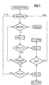
Zum Verständnis der Erfindung bietet es sich an, zunächst das erfindungsgemäße Verfahren gemäß der Figur 1 zu erläutern. Bei einer ansteigenden Flanke des Eingangssignales IN wird eine Zählvariable zurückgesetzt. Bei einer ansteigenden Flanke des Taktsignales int_clk wird die Zählvariable um 1 erhöht. Daraufhin wird die Zählvariable überprüft, ob sie den Wert nL erreicht hat. Ist dies nicht der Fall und eine ansteigende Flanke wurde nicht detektiert, so wird mit dem Weiterzählen auf eine Flanke des Taktsignales int_clk hin fortgesetzt. Wenn die Zählvariable den Wert nL erreicht, so bedeutet dies, daß die Periodendauer des Eingangssignales größer als Tmin ist. Die Frequenz ist damit kleiner als Fmin und ein erstes Ausgangssignal LF_Alarm wird ausgegeben. Wenn die Zählvariable noch nicht den Wert nL erreicht hat, jedoch ein Flankenanstieg des Eingangssignales IN detektiert wurde, so wird die Zählvariable daraufhin überprüft, ob ihr Wert kleiner oder gleich nH ist. Ist dies nicht der Fall, so liegt die Frequenz des Eingangssignales im zulässigen Bereich und der Zähler wird, da eine ansteigende Flanke detektiert wurde, zurückgesetzt. Ist die Zählervariable jedoch kleiner als nH, so ist die Periodendauer des Eingangssignales IN zu klein und ein zweiten Ausgangssignal HF_Alarm wird ausgegeben. Durch ein Reset-Signal kann das Verfahren wieder von vorne beginnen. To understand the invention, it is advisable to first explain the method according to the invention according to FIG. 1. A counting variable is reset on a rising edge of the input signal IN. The counting variable is increased by 1 on a rising edge of the clock signal int_clk. The counter variable is then checked to determine whether it has reached the value n L. If this is not the case and a rising edge has not been detected, counting continues on an edge of the clock signal int_clk. If the counter variable reaches the value n L , this means that the period of the input signal is longer than T min . The frequency is thus less than F min and a first output signal LF_Alarm is output. If the counter variable has not yet reached the value n L , but an edge rise in the input signal IN has been detected, the counter variable is checked to see whether its value is less than or equal to n H. If this is not the case, the frequency of the input signal is in the permissible range and the counter is reset because a rising edge has been detected. However, if the counter variable is less than n H , the period of the input signal IN is too short and a second output signal HF_Alarm is output. The process can start again from the beginning with a reset signal.
Figur 2 zeigt das zugehörige Zustandsdiagramm. Der Zustand
"0" markiert den Normalzustand, wenn die Frequenz im zulässigen
Bereich liegt. Die Bedingung A lautet "Zähler = nL". Ist
diese Bedingung erfüllt, so erfolgt ein Übergang in den Zustand
1L, das heißt die Frequenz des Eingangssignales wurde
als zu niedrig bewertet. Durch ein Reset-Signal wird der Zähler
zurückgesetzt und es erfolgt ein Übergang in den Normalzustand
"0". Die Bedingung B ist erfüllt, wenn die Zählvariable
kleiner als nH ist, wenn eine ansteigende Flanke detektiert
wurde. Der Zustand 1H zeigt an, daß die Frequenz des
Eingangssignales zu groß ist. Durch einen zurückgesetzten
Zähler gelangt man wiederum in den Normalzustand "0". Die Bedingung
C ist erfüllt, wenn die Zählvariable kleiner als nL
ist und die Zählvariable bei Auftreten einer ansteigenden
Flanke größer als nH ist. Wenn keine ansteigende Flanke detektiert
wurde, so genügt es, wenn die Zählvariable kleiner
als nL ist.Figure 2 shows the associated state diagram. State "0" marks the normal state if the frequency is within the permissible range. Condition A is "counter = n L ". If this condition is met, a transition to
Ein Blockschaltbild einer erfindungsgemäßen Schaltungsanordnung, also eines Frequenzsensors, ist in der Figur 3 dargestellt. Ein interne Taktsignal int clk wirkt sowohl auf einen Zähler BC, der als n-bit-Zähler ausgeführt ist, und auf einen Zustandsspeicher FSM. Das Eingangssignal IN wirkt auf einen Flankendetektor ED, der bei Detektion einer ansteigenden Flanke ein Signal an den Zustandsspeicher FSM gibt. Ein Reset-Signal setzt den Flankendetektor ED sowie den Zustandsspeicher FSM zurück. Dieser wiederum wirkt über ein entsprechendes Signal int_rst auf den Zähler BC, um den Zähler zurückzusetzen. Der aktuelle Stand des Zählers wird dem Zustandsspeicher FSM übergeben.A block diagram of a circuit arrangement according to the invention, a frequency sensor, is shown in FIG. 3. An internal clock signal int clk affects both Counter BC, which is designed as an n-bit counter, and on one State memory FSM. The input signal IN affects one Edge detector ED, which detects a rising Edge gives a signal to the state memory FSM. A reset signal sets the edge detector ED and the state memory FSM back. This in turn acts via a corresponding one Signal int_rst to counter BC to reset the counter. The current status of the counter becomes the status memory Handed over to FSM.
Statt des n-bit-Zählers kann natürlich auch ein anderer Zählerbaustein verwendet werden. Die Zustände des Zustandsspeichers FSM werden in Form von zwei Ausgangssignalen angezeigt, nämlich durch das LF_Alarm- und das HF_Alarm-Signal. Die Logik der Anordnung kann so ausgelegt werden, daß der Frequenzsensor nur dann erneut beginnt zu messen, wenn ein Reset-Signal auf den entsprechenden Eingang des Frequenzsensors gegeben wird, oder aber nach einer gewissen Zeitspanne beginnt die Anordnung erneut die Frequenz zu überwachen, indem automatisch ein Reset-Signal generiert wird. Eine dritte Möglichkeit besteht darin, die Alarmanzeige zurückzusetzen, sobald in einer fortlaufenden Messung festgestellt wurde, daß die Frequenz nun wieder im zulässigen Bereich liegt. Die Ausgabe der Signale LF_Alarm und HF_Alarm hätten somit eine rein anzeigende Wirkung.Instead of the n-bit counter, another counter module can of course also be used be used. The states of the state memory FSM are displayed in the form of two output signals, namely by the LF_Alarm and the HF_Alarm signal. The logic the arrangement can be designed so that the frequency sensor only starts measuring again when a reset signal given to the corresponding input of the frequency sensor becomes, or begins after a certain period of time the arrangement again monitor the frequency by automatically a reset signal is generated. A third option is to reset the alarm indicator as soon as in a continuous measurement it was found that the Frequency is again in the permissible range. The edition the signals LF_Alarm and HF_Alarm would have a purely indicating Effect.
In der Figur 4 sind die Signalverläufe der Signale der Anordnung
von Figur 3 angegeben. Im dargestellten Beispiel ist die
Frequenz des Eingangssignales IN zu gering, das heißt die Periodendauer
TIN ist zu groß. Mit der ansteigenden Flanke des
Eingangssignales IN wird der Zähler auf Null zurückgesetzt.
Mit dem Taktsignal int_clk wird die Zählvariable nun so lange
weitergezählt, bis sie den Wert nL erreicht. Da bis zu diesem
Zeitpunkt noch keine weitere ansteigende Flanke detektiert
wurde und somit der Zähler nicht zurück gesetzt wurde, geht
der Zustandsspeicher in den Zustand 1L über und das Ausgangssignal
LF_Alarm nimmt den HIGH-Pegel ein.FIG. 4 shows the signal profiles of the signals of the arrangement from FIG. 3. In the example shown, the frequency of the input signal IN is too low, that is, the period T IN is too large. The counter is reset to zero with the rising edge of the input signal IN. With the clock signal int_clk, the counter variable is counted until it reaches the value n L. Since no further rising edge has yet been detected and the counter has not been reset, the state memory changes to
Claims (6)
dadurch gekennzeichnet, daß die Frequenz des Taktsignales (int_clk) größer ist als die obere Frequenz (Fmax) des erlaubten Frequenzbereiches. Frequency sensor according to claim 1,
characterized in that the frequency of the clock signal (int_clk) is greater than the upper frequency (F max ) of the permitted frequency range.
dadurch gekennzeichnet, daß Frequenz des Taktsignales (int_clk) mindestens zehnmal größer ist als die obere Frequenz (Fmax) des erlaubten Frequenzbereiches.Frequency sensor according to claim 2,
characterized in that the frequency of the clock signal (int_clk) is at least ten times greater than the upper frequency (F max ) of the permitted frequency range.
dadurch gekennzeichnet, daß die Frequenz des Taktsignales (int_clk) größer ist als die obere Frequenz (Fmax) des erlaubten Frequenzbereiches.Frequency sensor according to claim 4,
characterized in that the frequency of the clock signal (int_clk) is greater than the upper frequency (F max ) of the permitted frequency range.
dadurch gekennzeichnet, daß Frequenz des Taktsignales (int_clk) mindestens zehnmal größer ist als die obere Frequenz (Fmax) des erlaubten Frequenzbereiches.Frequency sensor according to claim 5,
characterized in that the frequency of the clock signal (int_clk) is at least ten times greater than the upper frequency (F max ) of the permitted frequency range.
Priority Applications (2)
| Application Number | Priority Date | Filing Date | Title |
|---|---|---|---|
| EP00106268A EP1136830A1 (en) | 2000-03-22 | 2000-03-22 | Frequency sensing device for digital signals and method for monitoring the frequency of a digital signal |
| PCT/DE2001/001087 WO2001071368A1 (en) | 2000-03-22 | 2001-03-21 | Frequency sensor for digital signals and method for monitoring the frequency of a digital signal |
Applications Claiming Priority (1)
| Application Number | Priority Date | Filing Date | Title |
|---|---|---|---|
| EP00106268A EP1136830A1 (en) | 2000-03-22 | 2000-03-22 | Frequency sensing device for digital signals and method for monitoring the frequency of a digital signal |
Publications (1)
| Publication Number | Publication Date |
|---|---|
| EP1136830A1 true EP1136830A1 (en) | 2001-09-26 |
Family
ID=8168206
Family Applications (1)
| Application Number | Title | Priority Date | Filing Date |
|---|---|---|---|
| EP00106268A Withdrawn EP1136830A1 (en) | 2000-03-22 | 2000-03-22 | Frequency sensing device for digital signals and method for monitoring the frequency of a digital signal |
Country Status (2)
| Country | Link |
|---|---|
| EP (1) | EP1136830A1 (en) |
| WO (1) | WO2001071368A1 (en) |
Cited By (1)
| Publication number | Priority date | Publication date | Assignee | Title |
|---|---|---|---|---|
| US7504865B2 (en) | 2004-03-09 | 2009-03-17 | Panasonic Corporation | Frequency sensor and semiconductor device |
Citations (5)
| Publication number | Priority date | Publication date | Assignee | Title |
|---|---|---|---|---|
| US4137496A (en) * | 1977-09-16 | 1979-01-30 | Lind Leroy R | Line frequency deviation monitor |
| US4486752A (en) * | 1982-03-29 | 1984-12-04 | Rockwell International Corporation | Pulse width discriminator applicable to ATC transponders |
| DE3713802A1 (en) * | 1986-04-25 | 1987-11-05 | Mitsubishi Electric Corp | DETECTOR CIRCUIT FOR DETECTING A FREQUENCY DEVIATION FROM NORMAL VALUE |
| EP0403396A1 (en) * | 1989-06-16 | 1990-12-19 | Jaeger | Device for monitoring the operation of a microcontroller or microprocessor |
| EP0788227A2 (en) * | 1996-02-05 | 1997-08-06 | Mitsubishi Electric Semiconductor Software Co., Ltd. | Timer apparatus |
-
2000
- 2000-03-22 EP EP00106268A patent/EP1136830A1/en not_active Withdrawn
-
2001
- 2001-03-21 WO PCT/DE2001/001087 patent/WO2001071368A1/en not_active Ceased
Patent Citations (5)
| Publication number | Priority date | Publication date | Assignee | Title |
|---|---|---|---|---|
| US4137496A (en) * | 1977-09-16 | 1979-01-30 | Lind Leroy R | Line frequency deviation monitor |
| US4486752A (en) * | 1982-03-29 | 1984-12-04 | Rockwell International Corporation | Pulse width discriminator applicable to ATC transponders |
| DE3713802A1 (en) * | 1986-04-25 | 1987-11-05 | Mitsubishi Electric Corp | DETECTOR CIRCUIT FOR DETECTING A FREQUENCY DEVIATION FROM NORMAL VALUE |
| EP0403396A1 (en) * | 1989-06-16 | 1990-12-19 | Jaeger | Device for monitoring the operation of a microcontroller or microprocessor |
| EP0788227A2 (en) * | 1996-02-05 | 1997-08-06 | Mitsubishi Electric Semiconductor Software Co., Ltd. | Timer apparatus |
Non-Patent Citations (1)
| Title |
|---|
| J.SKINNER: "Digital frequency window", ELECTRONIC ENGINEERING, vol. 60, no. 739, July 1988 (1988-07-01), GB, pages 27, XP002147205 * |
Cited By (1)
| Publication number | Priority date | Publication date | Assignee | Title |
|---|---|---|---|---|
| US7504865B2 (en) | 2004-03-09 | 2009-03-17 | Panasonic Corporation | Frequency sensor and semiconductor device |
Also Published As
| Publication number | Publication date |
|---|---|
| WO2001071368A1 (en) | 2001-09-27 |
Similar Documents
| Publication | Publication Date | Title |
|---|---|---|
| DE60026962T2 (en) | Adjustable harmonic distortion detector and method using this detector | |
| DE2948330C2 (en) | Method and device for frequency measurement | |
| DE2727201A1 (en) | TOUCH CONTROL BUTTONS | |
| DE102008039195A1 (en) | Method for detecting the frequency of an input clock signal of an integrated circuit and integrated circuit | |
| DE112009003680T5 (en) | Method for determining the frequency or period of a signal | |
| EP0017251B1 (en) | Circuitry for determining the mean period length of a periodical signal | |
| DE102008059791A1 (en) | Automatic-averaging RC time constant calibration | |
| DE102006055844A1 (en) | Capacitive sensor for a physical size, as well as methods for its diagnosis | |
| DE68913243T2 (en) | Phase detector for gradually determining a phase relationship. | |
| EP0231786B1 (en) | Process for eliminating disturbances in measuring signals | |
| EP1494038B1 (en) | Method and device for the determination of the ratio of a RC time constant in an integrated circuit to a set value | |
| DE102005024648A1 (en) | Electrical circuit for measuring times and method for measuring times | |
| DE4211701A1 (en) | Method and device for phase measurement | |
| DE102006041827B4 (en) | Method for determining a time interval | |
| EP1136830A1 (en) | Frequency sensing device for digital signals and method for monitoring the frequency of a digital signal | |
| DE69028326T2 (en) | Signal level detection circuits | |
| DE69616267T2 (en) | time switch | |
| DE10319899B4 (en) | A method and frequency comparing means for generating a control signal indicative of a frequency deviation | |
| DE2142711C3 (en) | Signal test circuit for signals for which certain tolerance ranges are specified | |
| DE60033112T2 (en) | Apparatus for measuring the duration of a synchronization signal and display device | |
| DE3340455A1 (en) | Circuit arrangement for counting pulse lengths | |
| DE2722981B2 (en) | Digital filter for binary signals | |
| DE2712847C3 (en) | Speech-protected, frequency-selective character receiver | |
| EP0706054B1 (en) | Phase comparator | |
| AT397591B (en) | MEASURING DEVICE FOR DETECTING AND DISPLAYING VARIOUS MEASURED VALUES, ESPECIALLY FOR MEASURING VALUES IN NETWORKS OF DIALING SYSTEMS |
Legal Events
| Date | Code | Title | Description |
|---|---|---|---|
| PUAI | Public reference made under article 153(3) epc to a published international application that has entered the european phase |
Free format text: ORIGINAL CODE: 0009012 |
|
| AK | Designated contracting states |
Kind code of ref document: A1 Designated state(s): AT BE CH CY DE DK ES FI FR GB GR IE IT LI LU MC NL PT SE |
|
| AX | Request for extension of the european patent |
Free format text: AL;LT;LV;MK;RO;SI |
|
| AKX | Designation fees paid | ||
| REG | Reference to a national code |
Ref country code: DE Ref legal event code: 8566 |
|
| STAA | Information on the status of an ep patent application or granted ep patent |
Free format text: STATUS: THE APPLICATION IS DEEMED TO BE WITHDRAWN |
|
| 18D | Application deemed to be withdrawn |
Effective date: 20020327 |