EP1136816A2 - Analyseur spectral à rayons X avec mécanisme d'observation de la surface de l'échantillon - Google Patents
Analyseur spectral à rayons X avec mécanisme d'observation de la surface de l'échantillon Download PDFInfo
- Publication number
- EP1136816A2 EP1136816A2 EP01105302A EP01105302A EP1136816A2 EP 1136816 A2 EP1136816 A2 EP 1136816A2 EP 01105302 A EP01105302 A EP 01105302A EP 01105302 A EP01105302 A EP 01105302A EP 1136816 A2 EP1136816 A2 EP 1136816A2
- Authority
- EP
- European Patent Office
- Prior art keywords
- sample
- ray
- analyzer
- residue
- illuminating
- Prior art date
- Legal status (The legal status is an assumption and is not a legal conclusion. Google has not performed a legal analysis and makes no representation as to the accuracy of the status listed.)
- Withdrawn
Links
Images

Classifications
-
- G—PHYSICS
- G01—MEASURING; TESTING
- G01N—INVESTIGATING OR ANALYSING MATERIALS BY DETERMINING THEIR CHEMICAL OR PHYSICAL PROPERTIES
- G01N23/00—Investigating or analysing materials by the use of wave or particle radiation, e.g. X-rays or neutrons, not covered by groups G01N3/00 – G01N17/00, G01N21/00 or G01N22/00
- G01N23/02—Investigating or analysing materials by the use of wave or particle radiation, e.g. X-rays or neutrons, not covered by groups G01N3/00 – G01N17/00, G01N21/00 or G01N22/00 by transmitting the radiation through the material
- G01N23/04—Investigating or analysing materials by the use of wave or particle radiation, e.g. X-rays or neutrons, not covered by groups G01N3/00 – G01N17/00, G01N21/00 or G01N22/00 by transmitting the radiation through the material and forming images of the material
-
- G—PHYSICS
- G01—MEASURING; TESTING
- G01N—INVESTIGATING OR ANALYSING MATERIALS BY DETERMINING THEIR CHEMICAL OR PHYSICAL PROPERTIES
- G01N23/00—Investigating or analysing materials by the use of wave or particle radiation, e.g. X-rays or neutrons, not covered by groups G01N3/00 – G01N17/00, G01N21/00 or G01N22/00
- G01N23/22—Investigating or analysing materials by the use of wave or particle radiation, e.g. X-rays or neutrons, not covered by groups G01N3/00 – G01N17/00, G01N21/00 or G01N22/00 by measuring secondary emission from the material
- G01N23/223—Investigating or analysing materials by the use of wave or particle radiation, e.g. X-rays or neutrons, not covered by groups G01N3/00 – G01N17/00, G01N21/00 or G01N22/00 by measuring secondary emission from the material by irradiating the sample with X-rays or gamma-rays and by measuring X-ray fluorescence
Definitions
- the present invention relates to an X-ray spectroscopic analyzer having a sample surface observation mechanism, for observing a sample surface of, such as, a semiconductor wafer, etc.
- a silicon wafer which is treated on a semiconductor manufacture line, is sometimes contaminated upon the surfaces thereof, on a way of processing thereof.
- the sample must be set into the X-ray spectroscopic analyzer, again after specifying the contaminated portion by the separated analyzer, therefore the operation comes to be troublesome, and there is a possibility that the sample is further contaminated on the way of transportation for re-setting thereof into the X-ray spectroscopic analyzer.
- the fluorescence X-ray does not generate from the position of the residue with a sufficient intensity thereof, even when the X-ray is irradiated thereupon, therefore it is difficult to specify the position of the residue.
- amaterial, including a specific chemical element(s) therein is added in advance into the solution, such as, hydrofluoric acid, or into the solution to be dripped, thereby to identify or specify the position of the residue by means of the intensity of the X-ray which is generated from that material.
- the sample is contaminated further more with that additional material, therefore it is not a method being applicable in general.
- an object according to the present invention is, for dissolving such the drawbacks in the conventional arts mentioned above, to provide an X-ray spectroscopic analyzer having a mechanism for observing a sample surface, with which a shape can be clearly observed of the contaminated portion, the residue or the like, upon the sample surface under dark field, but in a condition of maintaining the sample being set in the X-ray spectroscopic analyzer.
- an X-ray spectroscopic analyzer for analyzing a sample by irradiating X-ray thereupon within a chamber, having a mechanism for observing a sample surface therethrough, comprising: a viewer apparatus for letting the sample to be viewed therethrough; and an illumination means for illuminating a surface of the sample, by irradiating an illuminating light upon the surface of said sample obliquely, while suppressing an incidence of a reflection light from the illumination light upon said viewer apparatus.
- the X-ray spectroscopic analyzer having a mechanism for observing a sample surface, as described in the above, further comprising, a moving means for moving the sample at least between an X-ray irradiation position where the X-ray is irradiated upon and a viewing position where a view is made upon, and a position indicator means for indicating the viewing position on the sample thereupon.
- the sample can be positioned automatically by means of the moving means, so that the X-ray can be irradiated upon that viewing position, such as the contaminated portion or the residue on the sample surface, which is displayed on the position indicator means.
- the X-ray spectroscopic analyzer having a mechanism for observing a sample surface, as described in the above, wherein said viewer apparatus comprises an image pickup element for taking a picture of the surface of said sample, so as to output a video signal of an electrical one.
- the condition of the sample surface, being observed by the viewer apparatus can be displayed on a display screen of a computer, etc., therefore the sample surface can be observed easily.
- the X-ray spectroscopic analyzer having a mechanism for observing a sample surface, as described in the above, further comprising, an illumination adjusting means, being positioned on an optical path of the illumination light from said illumination means, for adjusting at least one of an illuminating direction and an illuminating angle of the illumination light with respect to the sample.
- the illuminating direction and/or the illuminating angle of the illumination light to be irradiated upon the sample can be changed freely by the illumination adjusting means, therefore it is possible to observe the condition of the contamination and/or the shape of the residue, much more clearly.
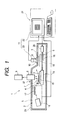
- Fig. 1 is a general structure view of an X-ray spectroscopic analyzer, according to an embodiment of the present invention.
- This X-ray spectroscopic analyzer 1 shown herein is a so-called a total reflection X-ray spectroscopic analyzer, which irradiates X-ray upon a surface of a sample 3 having an optical plane, such as, a semiconductor wafer, within a chamber 2, so as to perform a spectroscopic analysis upon chemical elements of the sample 3.
- This X-ray spectroscopic analyzer 1 comprises an X-ray source 5 for generating a primary X-ray 4 therefrom, a moving means 6 for moving the sample 3 in the horizontal direction, a detector for detecting fluorescence X-ray 7 generating from the sample surface due to the irradiation of the primary X-ray 4 thereupon, an analyzer 9 for identifying the chemical element(s) upon the sample surface on the basis of an output of the detector 8, a viewer apparatus 11 for letting the sample 3 to be viewed through a window provided on a wall 2a of the above-mentioned chamber 2, and a (matrix-like) squared or sectioned member 12.
- the above-mentioned X-ray source 5 comprises an X-ray generator 16 and a spectroscope 17 made of a spectrum crystal or an artificial thin-film grating of multi-layers, and it emits a monochromatic X-ray through the spectroscope 17 onto the sample surface at an incident angle ⁇ , being equal or less than 0.1° in general, thereby totally reflecting it thereon.
- the above-mentioned moving means 6 has a X-Y stage 19, on which is mounted a sample holder 18 for supporting the sample 3 thereon, being freely movable horizontally in orthogonal two-axial directions, and a driving apparatus 20 for moving that X-Y stage 19 horizontally to desired positions, including a X-ray irradiation position where the X-ray is irradiated upon when analyzing, as is indicated by a solid line, and a viewing position opposing to the window 10, as is indicated by a two-dot chain line.
- the X-Y stage 19 is moved further into a side of a distance sensor 37 which will be mentioned later (i.e., the left-hand side) when the height of the sample 3 is measured by that distance sensor 37.
- the X-ray source 5 and the moving means 6 mentioned above are controlled by a computer 21 being constructed with a display, etc.
- the above-mentioned viewer apparatus 11 is constructed with an image pickup device or element 23 (hereinafter, being called by a CCD camera), which takes a picture on the surface of the sample 3, to output a video signal as an electrical one, and a display device 22 of the above-mentioned computer 21 for displaying the picture of the sample surface upon the basis of the video signal from that CCD camera 23.
- a CCD camera image pickup device or element 23
- the above-mentioned CCD camera 23 is connected through a lens system 24, comprising a macro-lens, a zoom lens, etc., to a mirror cylinder 25, a lower end of which faces onto the window 10 on the chamber wall 2a mentioned above.
- mirror cylinder 25 there are provided a lead glass 26 and an iris 27, and a ring-like lead glass 28 is disposed in an opening defined between the lower end of the mirror cylinder 25 and the window 10 mentioned above, thereby preventing the X-ray from leaking outside the chamber 2.
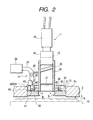
- an illumination means 31 for illuminating the surface of the sample 3, being disposed below the window 10, thereby guiding an illumination light from a peripheral portion of that window 10 obliquely down to a central portion thereof.
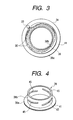
- This illumination means 31 has a bundle of optical fibers 33 for guiding the illumination light from a light source 32, such as, a halogen lump, etc., and that bundle of optical fibers 33 is disposed within a light guiding member 34 provided surrounding the mirror cylinder 25, as shown by a plan view in Fig. 3, so that each fiber tip portion 35 is directed radially to the central portion of the window 10, forming a light emitting portion at a terminal end of the optical fiber.
- the fiber tip portion 35 at the terminal end of each one of the optical fibers, is radically distributed and supported within the light guiding member 34, so that it is positioned to incline at a predetermined down angle (for example, 18°) to the horizontal plan, in a direction of a radius directing to the central portion of the window 10.
- a predetermined down angle for example, 18°
- a ring 38 is disposed concentrically with the light guiding member 34.
- This ring 38 is positioned on a light path of the illumination light irradiated from the fiber tip portions 35, so that the illumination light is selectively adjusted to be interrupted by or penetrate through it, and is movable rotationally around the ring center through a rotational driving apparatus 39 shown in the Fig. 2.
- an illumination adjuster apparatus 40 is constructed, according to the present invention.
- the ring 38 mentioned above comprises a bottom plate 38a made from a ring-like flat plate and a cylinder-like peripheral wall 38b, as shown in the perspective view of Fig. 4, wherein at different positions around the peripheral wall 38b are opened a plural number of slits 45, being inclined in a direction of the periphery thereof.
- the rotational driving apparatus 39 shown in the Fig. 2 is constructed with a gear 41, which is formed at a lower end of the above-mentioned ring 38 concentrically with therewith, a pinion 42 meshed with that gear 41, and driving machine 43 for driving that pinion 42 rotationally, for example, a servo motor.
- the illumination light which is guided from the light source 32 through the bundle of optical fibers 33 onto the sample surface, can be changed freely in an irradiating direction on a plane parallel to the sample surface, as well as an irradiating angle on a plane orthogonal thereto, therefore, it can be irradiated upon the sample surface from the peripheral portion of the window 10 into a direction of the central portion thereof at a desired down angle, as shown by an arrow B.
- the matrix-like squared member 12, functioning as the position indicator means for indicating the view position on the sample 3, is made by drawing squares on the surface of a transparent thin plate.
- This squared member 12 is positioned on a way of the lens system 24.
- squares 36 are added on a picture displayed upon the display screen 22a of the above-mentioned display device 22, as a standard or marks for confirming the position on it.
- Correspondence can be made between the squares 36 and a coordinate position on the surface of the sample 3 by a plane rectangular coordinates (i.e., an X-Y coordinates) which the X-Y stage 19 has.
- a position at the origin on the squares 36 is inputted into the computer 21 as the coordinate position for indicating the present position of the X-Y stage 19 of the moving means 19, therefore the coordinates on the surface of the sample 3 comes to be (the coordinates at the origin on the squares 36) + (the coordinates on the squares 36).
- the coordinate values of the residue A are read out by eyesight on the display screen 22a of the display device 22, on which the squares 36 are displayed, and thereafter the read-out coordinate values are inputted manually into the computer 21, thereby the position of the residue A is inputted into the computer 21 as the coordinate values, i.e., (the read-out coordinate values) + (the coordinate values of the origin).
- an indication is also possible of the view position on the sample 3 but reading out the coordinate values, for example, by clicking the residue A on the display screen 22a, when controlling the moving means 6 by the computer 21 and also calculating out the relationship between the sample 3 and the X-Y stage 19 by that at the same time.
- a clicking means such as a mouse, may construct the position indicator means according to the present invention.
- a laser device 27 being provided in the vicinity of the detector 8, constructs a distance sensor for detecting a height of the surface of the sample 3, which is positioned below the detector 8.
- the computer 21 controls the moving means 6, to move the sample 3 held on the sample holder 18, horizontally, up to such the position, that the center thereof comes to be coincident with that of the window 10 formed on the chamber 2.
- the surface of the sample 3 is observed by means of the viewer apparatus 11. Namely, the surface picture of the sample 3 is picked up by the CCD camera 23, and then the picture of the sample surface is displayed on the display device 22. upon the basis of the video signal as the output thereof, therefore the condition of the residue A (see the Fig. 3) can be observed on the sample surface through that picture. In this manner, since the sample surface can be observed through the picture displayed on the screen of the display device 22, the operation of observation comes to be easy. Further, the focus of the CCD camera 23 is adjusted upon the basis of information of the height of the sample surface, which is detected by the laser 37 for use in detecting a height.
- the illumination light B is irradiated upon the sample surface from the peripheral portion of the window 10, obliquely, directing to the central portion thereof, however, since it never enter into the CCD camera 23 directly, the condition of residue A can be observed clearly under a condition of dark field.
- the squares 36 of the squared member 12 are added onto the screen mentioned above, functioning as the position indicator means or the standard or marks for positioning by the eyesight, therefore the positional coordinates (X,Y) of the residue A can be confirmed easily, by using the squares functioning as that standard or marks. Namely, the coordinates of the residue A are read out on the X-Y coordinates, which are indicated on the display screen 22a of the display device 22. The origin of that X-Y coordinates may be, for example, the central point of the sample.
- the computer 21 controls the moving means 6, so as to horizontally move the sample 3 up to such the position, that the primary X-ray from the X-ray source 5 irradiates upon that residue A, thereby conducting the X-ray spectroscopic analysis thereon.
- the fluorescence X-ray 7 generating from the residue A on the sample surface is detected by the detector 8, and the chemical element(s) of the impurities contained in that residue A is identified by the analyzer 9, upon the basis of the output from the detector 8.
- the explanation was made only on the case where the X-ray spectroscopic analysis is made upon the residue A on the sample surface, however, also in a case where the X-ray spectroscopic analysis is made upon the contaminated portion on the sample surface directly, it may be made after making the observation on the contaminated portion and the confirmation on the position thereof, in the same steps, thereby enabling the effective X-ray spectroscopic analysis thereof.
- the lens system 24 in the viewer apparatus 11 is indicated to be constructed with the macro lens and the zoom lens, for example, in the embodiment mentioned above, however, other than that, it can be constructed with a zoom unit, a twin lens, etc., combining with various illuminations of, such as, a coaxial top light, an oblique top light, a polarization light, an oblique light, etc., for obtaining the observation being suitable for various kinds of foreign matters adhered on the sample surface.
- the present invention should not be restricted only to that, and in the place thereof, the view may be made on the sample 3 at the position where the primary X-ray 4 is irradiated, while illuminating the surface of the sample 3.
- the inclined slots 45 on the peripheral wall 38a of the ring 38 are changed in the position thereof, and with this, the illumination light, being irradiated from the each fiber tip portion 35, can be interrupted by or penetrate through it, selectively. Accordingly, it is possible to irradiate the illumination light upon the sample surface from such appropriate direction and angle, that the residue A can be seen easily.
- an X-ray spectroscopic analyzer having an observation mechanism, for observing a sample surface therethrough comprises: a viewer apparatus for letting the sample to be viewed therethrough; and an illumination means for illuminating a surface of the sample, by irradiating an illumination light upon the surface of said sample obliquely, while suppressing an incidence of a reflection light from the illumination light upon said viewer apparatus, therefore, a shape of the contaminated portion, the residue or the like, upon the sample surface, can be clearly observed on the viewer apparatus under dark field, with keeping the sample set within the X-ray spectroscopic analyzer.
Landscapes
- Physics & Mathematics (AREA)
- Health & Medical Sciences (AREA)
- Life Sciences & Earth Sciences (AREA)
- Chemical & Material Sciences (AREA)
- Analytical Chemistry (AREA)
- Biochemistry (AREA)
- General Health & Medical Sciences (AREA)
- General Physics & Mathematics (AREA)
- Immunology (AREA)
- Pathology (AREA)
- Analysing Materials By The Use Of Radiation (AREA)
- Testing Or Measuring Of Semiconductors Or The Like (AREA)
Applications Claiming Priority (2)
| Application Number | Priority Date | Filing Date | Title |
|---|---|---|---|
| JP2000062093A JP2001249090A (ja) | 2000-03-07 | 2000-03-07 | 試料表面の観察機構を持つx線分析装置 |
| JP2000062093 | 2000-03-07 |
Publications (2)
| Publication Number | Publication Date |
|---|---|
| EP1136816A2 true EP1136816A2 (fr) | 2001-09-26 |
| EP1136816A3 EP1136816A3 (fr) | 2003-01-29 |
Family
ID=18582148
Family Applications (1)
| Application Number | Title | Priority Date | Filing Date |
|---|---|---|---|
| EP01105302A Withdrawn EP1136816A3 (fr) | 2000-03-07 | 2001-03-06 | Analyseur spectral à rayons X avec mécanisme d'observation de la surface de l'échantillon |
Country Status (5)
| Country | Link |
|---|---|
| US (1) | US20010021240A1 (fr) |
| EP (1) | EP1136816A3 (fr) |
| JP (1) | JP2001249090A (fr) |
| KR (1) | KR20010088425A (fr) |
| TW (1) | TW461966B (fr) |
Families Citing this family (14)
| Publication number | Priority date | Publication date | Assignee | Title |
|---|---|---|---|---|
| KR100609603B1 (ko) * | 2002-05-17 | 2006-08-04 | 주식회사 미르기술 | 엑스레이 및 비주얼검사가 통합된 인쇄회로기판 검사장치 |
| DE10230990A1 (de) * | 2002-07-10 | 2004-02-05 | Elisabeth Katz | Vorrichtung zur Durchführung einer Online-Elementanalyse |
| KR100543469B1 (ko) | 2003-12-23 | 2006-01-20 | 삼성전자주식회사 | 웨이퍼 홀더 및 웨이퍼 홀더가 구비된 웨이퍼 운반 장치 |
| DE102006008840B4 (de) * | 2006-02-25 | 2009-05-14 | Fraunhofer-Gesellschaft zur Förderung der angewandten Forschung e.V. | Beleuchtungsvorrichtung für zylindrische Objekte, damit durchgeführtes Oberflächenuntersuchungsverfahren und Computerprogrammprodukt |
| KR100899011B1 (ko) * | 2007-05-04 | 2009-05-21 | (주) 브이에스아이 | 카메라모듈과 반사형 근접센서를 이용한 휴대용 엑스선형광 금속분석장치 및 금속분석방법 |
| JP4630313B2 (ja) * | 2007-07-24 | 2011-02-09 | 株式会社リガク | X線分析装置 |
| JP5235447B2 (ja) * | 2008-02-22 | 2013-07-10 | 株式会社日立ハイテクサイエンス | X線分析装置及びx線分析方法 |
| JP5307504B2 (ja) * | 2008-08-22 | 2013-10-02 | 株式会社日立ハイテクサイエンス | X線分析装置及びx線分析方法 |
| US7972062B2 (en) * | 2009-07-16 | 2011-07-05 | Edax, Inc. | Optical positioner design in X-ray analyzer for coaxial micro-viewing and analysis |
| JP2016017823A (ja) * | 2014-07-08 | 2016-02-01 | 株式会社日立ハイテクサイエンス | X線分析用試料板及び蛍光x線分析装置 |
| KR102128656B1 (ko) | 2018-08-24 | 2020-06-30 | 정준용 | 스테인레스 전용 금속성분 분석방법 및 스테인레스 전용 금속성분 분석장치 |
| CN111487270A (zh) * | 2020-04-20 | 2020-08-04 | 厦门汇美集智科技有限公司 | 一种射线诱导发光装置 |
| DE102021127537A1 (de) | 2021-10-22 | 2023-04-27 | Helmut Fischer GmbH Institut für Elektronik und Messtechnik | Verfahren und Messgerät zur Messung von Messobjekten mittels Röntgenfluoreszenz |
| JP7833276B2 (ja) * | 2021-11-18 | 2026-03-19 | 株式会社堀場製作所 | X線分析装置、x線分析方法、及び、x線分析用プログラム |
Family Cites Families (7)
| Publication number | Priority date | Publication date | Assignee | Title |
|---|---|---|---|---|
| US4377340A (en) * | 1980-10-24 | 1983-03-22 | Hamamatsu Systems, Inc. | Method and apparatus for detecting particles on a material |
| JPH06281600A (ja) * | 1993-03-29 | 1994-10-07 | Sanyo Electric Co Ltd | 全反射蛍光x線分析装置 |
| US5825482A (en) * | 1995-09-29 | 1998-10-20 | Kla-Tencor Corporation | Surface inspection system with misregistration error correction and adaptive illumination |
| US5801824A (en) * | 1996-11-25 | 1998-09-01 | Photon Dynamics, Inc. | Large area defect monitor tool for manufacture of clean surfaces |
| JPH1172449A (ja) * | 1997-08-28 | 1999-03-16 | Rigaku Ind Co | 蛍光x線分析方法および装置 |
| JP3101257B2 (ja) * | 1998-01-30 | 2000-10-23 | 理学電機工業株式会社 | 試料表面の検査方法およびこれを使用するx線分析装置 |
| JP4041606B2 (ja) * | 1998-12-04 | 2008-01-30 | 株式会社堀場製作所 | X線分析装置 |
-
2000
- 2000-03-07 JP JP2000062093A patent/JP2001249090A/ja active Pending
-
2001
- 2001-03-06 EP EP01105302A patent/EP1136816A3/fr not_active Withdrawn
- 2001-03-06 TW TW090105192A patent/TW461966B/zh not_active IP Right Cessation
- 2001-03-07 KR KR1020010011649A patent/KR20010088425A/ko not_active Ceased
- 2001-03-07 US US09/799,532 patent/US20010021240A1/en not_active Abandoned
Also Published As
| Publication number | Publication date |
|---|---|
| EP1136816A3 (fr) | 2003-01-29 |
| JP2001249090A (ja) | 2001-09-14 |
| KR20010088425A (ko) | 2001-09-26 |
| US20010021240A1 (en) | 2001-09-13 |
| TW461966B (en) | 2001-11-01 |
Similar Documents
| Publication | Publication Date | Title |
|---|---|---|
| EP1136816A2 (fr) | Analyseur spectral à rayons X avec mécanisme d'observation de la surface de l'échantillon | |
| US4772126A (en) | Particle detection method and apparatus | |
| US4895446A (en) | Particle detection method and apparatus | |
| US6545755B1 (en) | Micro-Raman spectroscopy system for identifying foreign material on a semiconductor wafer | |
| KR960002722A (ko) | 외부 미립자의 위치 조정 방법과 분석 방법 그리고 이에 사용되는 분석기 | |
| TWI480542B (zh) | A defect detection method and apparatus therefor, and a defect observation method and apparatus therefor | |
| CN102278941B (zh) | 测试装置 | |
| US9074992B2 (en) | X-ray diffraction apparatus and X-ray diffraction measurement method | |
| CN116359249A (zh) | 基于tdi的线扫描暗场散射晶圆表面缺陷检测装置及方法 | |
| US7023954B2 (en) | Optical alignment of X-ray microanalyzers | |
| JP2010096554A (ja) | 欠陥検出方法の高感度化 | |
| JP5416600B2 (ja) | 欠陥検査装置およびその方法 | |
| US4800282A (en) | Apparatus and method for detecting residual organic compounds | |
| JP3101257B2 (ja) | 試料表面の検査方法およびこれを使用するx線分析装置 | |
| JPH06302676A (ja) | ウエハ異物検査装置 | |
| US20090316981A1 (en) | Method and device for inspecting a disk-shaped object | |
| JP4630313B2 (ja) | X線分析装置 | |
| JP3736361B2 (ja) | 異物特定方法、異物特定装置、および発塵源特定方法 | |
| JP2782473B2 (ja) | 材料表面検査装置 | |
| JP2545209B2 (ja) | 結晶欠陥検査方法及びその検査装置 | |
| CN117849065A (zh) | 针对外延硅片近表面缺陷的无损定性检测装置及方法 | |
| JP2004347525A (ja) | 半導体チップ外観検査方法およびその装置 | |
| JP2602523B2 (ja) | カソードルミネッセンス測定装置 | |
| JPH0629853B2 (ja) | 光散乱画像情報解析装置 | |
| JPS63243855A (ja) | 荷電粒子分析装置 |
Legal Events
| Date | Code | Title | Description |
|---|---|---|---|
| PUAI | Public reference made under article 153(3) epc to a published international application that has entered the european phase |
Free format text: ORIGINAL CODE: 0009012 |
|
| AK | Designated contracting states |
Kind code of ref document: A2 Designated state(s): AT BE CH CY DE DK ES FI FR GB GR IE IT LI LU MC NL PT SE TR |
|
| AX | Request for extension of the european patent |
Free format text: AL;LT;LV;MK;RO;SI |
|
| PUAL | Search report despatched |
Free format text: ORIGINAL CODE: 0009013 |
|
| RIC1 | Information provided on ipc code assigned before grant |
Free format text: 7G 01N 23/20 A, 7G 01N 23/223 B, 7G 01N 23/207 B, 7G 01N 23/22 B |
|
| AK | Designated contracting states |
Designated state(s): AT BE CH CY DE DK ES FI FR GB GR IE IT LI LU MC NL PT SE TR |
|
| AX | Request for extension of the european patent |
Extension state: AL LT LV MK RO SI |
|
| AKX | Designation fees paid |
Designated state(s): DE FR IT |
|
| STAA | Information on the status of an ep patent application or granted ep patent |
Free format text: STATUS: THE APPLICATION IS DEEMED TO BE WITHDRAWN |
|
| 18D | Application deemed to be withdrawn |
Effective date: 20031001 |