EP1136423B1 - Device for limiting the maximum speed of a balancing hoist - Google Patents
Device for limiting the maximum speed of a balancing hoist Download PDFInfo
- Publication number
- EP1136423B1 EP1136423B1 EP01250086A EP01250086A EP1136423B1 EP 1136423 B1 EP1136423 B1 EP 1136423B1 EP 01250086 A EP01250086 A EP 01250086A EP 01250086 A EP01250086 A EP 01250086A EP 1136423 B1 EP1136423 B1 EP 1136423B1
- Authority
- EP
- European Patent Office
- Prior art keywords
- hoist
- housing
- threaded spindle
- cone
- stop element
- Prior art date
- Legal status (The legal status is an assumption and is not a legal conclusion. Google has not performed a legal analysis and makes no representation as to the accuracy of the status listed.)
- Expired - Lifetime
Links
Images

Classifications
-
- B—PERFORMING OPERATIONS; TRANSPORTING
- B66—HOISTING; LIFTING; HAULING
- B66D—CAPSTANS; WINCHES; TACKLES, e.g. PULLEY BLOCKS; HOISTS
- B66D3/00—Portable or mobile lifting or hauling appliances
- B66D3/18—Power-operated hoists
-
- B—PERFORMING OPERATIONS; TRANSPORTING
- B66—HOISTING; LIFTING; HAULING
- B66D—CAPSTANS; WINCHES; TACKLES, e.g. PULLEY BLOCKS; HOISTS
- B66D5/00—Braking or detent devices characterised by application to lifting or hoisting gear, e.g. for controlling the lowering of loads
- B66D5/02—Crane, lift hoist, or winch brakes operating on drums, barrels, or ropes
- B66D5/04—Crane, lift hoist, or winch brakes operating on drums, barrels, or ropes actuated by centrifugal force
-
- B—PERFORMING OPERATIONS; TRANSPORTING
- B66—HOISTING; LIFTING; HAULING
- B66D—CAPSTANS; WINCHES; TACKLES, e.g. PULLEY BLOCKS; HOISTS
- B66D2700/00—Capstans, winches or hoists
- B66D2700/02—Hoists or accessories for hoists
- B66D2700/023—Hoists
-
- B—PERFORMING OPERATIONS; TRANSPORTING
- B66—HOISTING; LIFTING; HAULING
- B66D—CAPSTANS; WINCHES; TACKLES, e.g. PULLEY BLOCKS; HOISTS
- B66D2700/00—Capstans, winches or hoists
- B66D2700/03—Mechanisms with latches or braking devices in general for capstans, hoists or similar devices as well as braking devices actuated electrically or by fluid under pressure
Definitions
- the invention relates to a Balancing hoist according to the preamble of claim 1.
- Balancing hoists are known, in particular from the patent publications US 5,553,832, US 5,522,581, US 5,556,077 and US 5,439,200.
- these Hoists the axial movement of a hollow piston in a rotary motion of a Rope or chain storage drum or a chain nut converted.
- These Transformation is done by means of a ball screw.
- either the spindle rotatably in a housing and the mother with the Drum longitudinally displaceable on the spindle at 5.553.832, 5.522.581, 5.556.077 Fig. 11 u. 5,439,200 Fig.
- the object of the invention is a balancing - hoist with a speed limiting device specify in the after a simple Functional test and a simple replacement of defective components is possible, without that the hoist previously released from the suspension and then consuming must be dismantled.
- the solution provides that one end of the threaded spindle in one from the outside accessible housing chamber protrudes, which is preferably closed like a lid, and that at the end of the spindle a device for limiting the upper speed of the Spindle is arranged.
- This limiting device is frictionally engaged with the spindle connected.
- the one or more stop elements are fixed inside the housing arranged.
- the idea of the invention is therefore to have the device in one separate housing chamber, which after removing a lid, the Housing chamber dust-tight closes, easily accessible from the outside. In these Housing chamber protrudes into the threaded spindle, which with the pivot axes of the Brake pawls is connected.
- the or each stop element is inside in this solution formed on the housing, for example, as a thickening of the housing wall on the Inside.
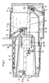
- Fig. 1 shows a Balancier hoist with a housing 10, which - with reference to FIG. 1 - right half is designed as a hollow cylinder 11.
- the hollow cylinder 11 is through a Cover 12 sealed with a seal 13 dustproof.
- a cylindrical piston 14 In the longitudinal direction of Hollow cylinder 11 is a cylindrical piston 14 with a sealing ring 15 slidably arranged.
- the piston 14 is located with a thrust bearing 16 at a face of a Cable drum 17, which via a feather key 18 with the right end of a Threaded spindle 19 is torsionally and rigidly connected.
- the cable drum 17 has on their outer circumference grooves 20 for receiving a wire rope 21.
- Die Threaded spindle 19 is rotatably mounted in a ball nut 19a which rotatably is arranged in the housing 10.
- the piston 14, the cable drum 17 and the threaded spindle 19 are shown in Fig. 1 in the upper half of the picture in her left and in the lower half in her right End position shown.
- the wire rope 21 on the Cable drum 17 In the left end position, the wire rope 21 on the Cable drum 17 fully wound (highest load position) and in the right End position completely unwound (lowest load position).
- the cable drum 17 expiring wire rope 21 exits through an opening 21a of the housing 10 and carries at its free end a payload, not shown.
- the threaded spindle 19 protrudes with their reference to FIG. 1 left end in one Housing chamber 22 which is closed dustproof with a lid 22a.
- Figs. 2 and 3 show the device for limiting the upper speed at removed cover 22a in a schematic representation (Fig. 3 as Cross section through the device of FIG. 2 along the line of sight III - III).
- a plate-shaped outer cone 23 attached to the outer ring two each about a pin-like pivot axis 25 pivotable pawls 24th are provided.
- the pawls 24 are biased by a spring 26 inwards pulled, so at standstill of the threaded spindle 19 in its standby position held.
- the transmissible torque may vary over the size of the Preload can be adjusted with the screw 29.
- the feather key 27a protrudes its left end in a recess of the disc 28, whereby the latter opposite the threaded spindle 19 is held against rotation.
- cam-like thickenings are arranged as a stop element 32, the to the threaded spindle 19 point.
- the functioning of the device is as follows: With increasing speed of the cable drum 17, the pawls 24 are moved about the pivot axes 25 against the retaining force of the springs 26 radially outward. At a limiting rotational speed of the threaded spindle 19 (and thus of the cable drum 17), surfaces 33 arranged on the pawls (contact surfaces) abut against the thickenings 32 and stop the rotational movement of the outer cone 23.
- the pins 30 limit in cooperation with a corresponding arrangement of Openings 31 the swivel angle of the pawls 24. They guarantee that only the Surfaces 33 come into contact with the stop elements 32. It is also achieved that the springs 26 are not overstretched.
Landscapes
- Engineering & Computer Science (AREA)
- Mechanical Engineering (AREA)
- Braking Arrangements (AREA)
- Centrifugal Separators (AREA)
- Load-Engaging Elements For Cranes (AREA)
Description
Die Erfindung betrifft ein
Balancier-Hebezeug gemäß dem Oberbegriff des Anspruchs 1.The invention relates to a
Balancing hoist according to the preamble of
Balancier-Hebezeuge sind bekannt, insbesondere aus den Patentveröffentlichungen US 5,553,832, US 5,522,581, US 5,556,077 und US 5,439,200. Bei diesen Hebezeugen wird die Axialbewegung eines Hohlkolbens in eine Drehbewegung einer Seil- oder Kettenspeichertrommel oder einer Kettennuß umgewandelt. Diese Umwandlung geschieht mittels eines Kugelgewindetriebes. Je nach gewähltem Prinzip ist hierbei entweder die Spindel drehfest in einem Gehäuse und die Mutter mit der Trommel längsverschieblich auf der Spindel (bei 5.553.832, 5.522.581, 5.556.077 Fig. 11 u. 5.439.200 Fig. 11) oder die Mutter ist axial fixiert und drehbar und die Spindel axial verschieblich und drehbehindert (bei 5.556.077 Fig. 1 u. 5.439.200 Fig. 1). Weiter weisen die bekannten Hebezeuge mehrere Klinken auf, die um eine zur Gewindespindel parallele Schwenkachse aus einer - radial gesehen - innen liegenden Ruhestellung in eine außen liegende Bremsstellung schwenkbar sind. Die Schwenkbewegung der Klinke erfolgt gegen eine rückstellende Federkraft. Die Klinke weist beim Drehen der Seiltrommel mit ihrem freien Ende jeweils in Drehrichtung. Aufgrund der vorspannenden Rückhaltekraft der Feder schwenkt die Klinke erst ab einer vorbestimmten Drehzahl fliehkraftbedingt mit ihrem freien Ende in die Bremsstellung. In der Bremsstellung verkeilen sich die Klinken schlagartig im feststehenden Gehäuse, wodurch die Drehung der Trommel oder der Kettennuß mit denen die Klinken formschlüssig verbunden sind, ebenfalls schlagartig gestoppt wird.Balancing hoists are known, in particular from the patent publications US 5,553,832, US 5,522,581, US 5,556,077 and US 5,439,200. In these Hoists, the axial movement of a hollow piston in a rotary motion of a Rope or chain storage drum or a chain nut converted. These Transformation is done by means of a ball screw. Depending on the selected principle Here, either the spindle rotatably in a housing and the mother with the Drum longitudinally displaceable on the spindle (at 5.553.832, 5.522.581, 5.556.077 Fig. 11 u. 5,439,200 Fig. 11) or the nut is axially fixed and rotatable and the spindle axially displaceable and rotationally restricted (at 5,556,077 Fig. 1 and 5,439,200 Fig. 1). Further have the known hoists several pawls, which is a for Threaded spindle parallel pivot axis from a - radially seen - inside Rest position are pivotable in an outboard braking position. The Pivoting movement of the pawl takes place against a restoring spring force. The handle points when turning the cable drum with its free end in each case in the direction of rotation. Due to the biasing retention force of the spring, the pawl pivots only a predetermined speed centrifugal force with its free end in the Braking position. In the braking position, the pawls suddenly abruptly wedged in fixed housing, whereby the rotation of the drum or the sprocket with where the pawls are positively connected, also stopped abruptly.
Die aus der US 5,553,832 bekannten Einrichtungen zur Begrenzung der oberen Drehzahl haben den Nachteil, dass sich die Klinken schlagartig im Gehäuse verkeilen und dadurch eine Stossbelastung auch in der Anschlusskonstruktion erzeugen, die in ihrer Stärke nicht beeinflussbar ist. Es kann zu Verformungen oder zum Bruch von zugehörigen Bauteilen kommen, so dass die Anschlusskonstruktionen und/oder das Hebezeug unbrauchbar ist. Folglich muss nach einem Schadensfall mit aktivgewordener Begrenzungseinrichtung eine Funktionsprüfung durchgeführt und einzelne Bauteile ggf. ersetzt werden. Die Funktionsprüfung als auch der Austausch einzelner Bauteile der Begrenzungseinrichtung sind bei den bekannten Hebezeugen nur nach einer aufwendigen Demontage möglich, bei der das Gerät zusätzlich von der Aufhängung getrennt werden muss.The known from US 5,553,832 means for limiting the upper speed have the Disadvantage that the pawls abruptly wedged in the housing and thus a Shock load also in the adjacent construction produce, not in their strength can be influenced. It may be due to deformation or breakage of it Components come, so that the connecting structures and / or the hoist is useless. Consequently, after a claim has become active with Limiting device performed a functional test and individual components possibly replaced. The functional test as well as the replacement of individual components the limiting device are in the known hoists only after one elaborate disassembly possible, in which the device in addition to the suspension must be disconnected.
Die Aufgabe der Erfindung ist es, ein Balancier - Hebezeug mit einer Drehzahlbegrenzungs einrichtung anzugeben, bei der nach eine einfache Funktionsprüfung und ein einfacher Austausch defekter Bauteile möglich ist, ohne dass das Hebezeug zuvor von der Aufhängung gelöst und anschließend aufwendig demontiert werden muss.The object of the invention is a balancing - hoist with a speed limiting device specify in the after a simple Functional test and a simple replacement of defective components is possible, without that the hoist previously released from the suspension and then consuming must be dismantled.
Die Lösung dieser Aufgabe ist durch die im Anspruch 1 angegebenen Merkmale
gegeben, durch die kennzeichnenden Merkmale der Unteransprüche ist die
Einrichtung in vorteilhafter Weise weiter ausgestaltet.The solution to this problem is achieved by the features specified in
Die Lösung sieht vor, dass ein Ende der Gewindespindel in eine von außen zugängliche Gehäusekammer ragt, die vorzugsweise deckelartig verschlossen ist, und dass am Ende der Spindel eine Einrichtung zum Begrenzen der oberen Drehzahl der Spindel angeordnet ist. Diese Begrenzungseinrichtung ist mit der Spindel reibschlüssig verbunden. Das oder die Stoppelemente sind innen am Gehäuse feststehend angeordnet. Der Erfindungsgedanke besteht folglich darin, die Einrichtung in einer separaten Gehäusekammer anzuordnen, die nach Entfernen eines Deckels, der die Gehäusekammer staubdicht verschließt, von außen leicht zugänglich ist. In diese Gehäusekammer ragt die Gewindespindel hinein, welche mit den Schwenkachsen der Bremsklinken verbunden ist. Das oder jedes Stoppelement ist bei dieser Lösung innen am Gehäuse ausgebildet, beispielsweise als Verdickung der Gehäusewand auf der Innenseite. The solution provides that one end of the threaded spindle in one from the outside accessible housing chamber protrudes, which is preferably closed like a lid, and that at the end of the spindle a device for limiting the upper speed of the Spindle is arranged. This limiting device is frictionally engaged with the spindle connected. The one or more stop elements are fixed inside the housing arranged. The idea of the invention is therefore to have the device in one separate housing chamber, which after removing a lid, the Housing chamber dust-tight closes, easily accessible from the outside. In these Housing chamber protrudes into the threaded spindle, which with the pivot axes of the Brake pawls is connected. The or each stop element is inside in this solution formed on the housing, for example, as a thickening of the housing wall on the Inside.
Ein Ausführungsbeispiel der Erfindung ist in der Zeichnung dargestellt und wird nachfolgend näher beschrieben. Es zeigen:
- Fig. 1
- einen Längsschnitt durch ein Balancier-Hebezeug,
- Fig. 2
- eine Ansicht der Einrichtung zur Begrenzung der Drehzahl,
- Fig. 3
- einen Querschnitt durch die Einrichtung gemäß Fig. 3 entlang der Sichtlinie III - III und
- Fig. 4
- einen Querschnitt gemäß Fig. 3 entlang der Sichtlinie IV - IV.
- Fig. 1
- a longitudinal section through a Balancier hoist,
- Fig. 2
- a view of the device for limiting the speed,
- Fig. 3
- a cross-section through the device of FIG. 3 along the line of sight III - III and
- Fig. 4
- a cross section according to FIG. 3 along the line of sight IV - IV.
Fig. 1 zeigt ein Balancier-Hebezeug mit einem Gehäuse 10, dessen - bezogen auf Fig.
1 - rechte Hälfte als Hohlzylinder 11 ausgebildet ist. Der Hohlzylinder 11 ist durch einen
Deckel 12 mit einer Dichtung 13 staubdicht verschlossen. In Längsrichtung des
Hohlzylinders 11 ist ein zylinderförmiger Kolben 14 mit einem Dichtring 15 verschiebbar
angeordnet. Der Kolben 14 liegt mit einem Axiallager 16 an einer Stimfläche einer
Seiltrommel 17 an, die über eine Passfeder 18 mit dem rechten Ende einer
Gewindespindel 19 dreh- und biegesteif verbunden ist. Die Seiltrommel 17 besitzt auf
ihrem äußeren Umfang Rillen 20 zur Aufnahme eines Drahtseils 21. Die
Gewindespindel 19 ist in einer Kugelumlaufmutter 19a drehbar gelagert, die drehfest
im Gehäuse 10 angeordnet ist.Fig. 1 shows a Balancier hoist with a
Der Kolben 14, die Seiltrommel 17 und die Gewindespindel 19 sind in Fig. 1 in der
oberen Bildhälfte in ihrer linken und in der unteren Bildhälfte in ihrer rechten
Endstellung dargestellt. In der linken Endstellung ist das Drahtseil 21 auf der
Seiltrommel 17 vollständig aufgewickelt (höchste Laststellung) und in der rechten
Endstellung vollständig abgewickelt (tiefste Laststellung). Das von der Seiltrommel 17
ablaufende Drahtseil 21 tritt durch eine Öffnung 21a aus dem Gehäuse 10 aus und
trägt an seinem freien Ende eine nicht gezeigte Nutzlast.The
Die Gewindespindel 19 ragt mit ihren bezogen auf Fig. 1 linken Ende in eine
Gehäusekammer 22, die mit einem Deckel 22a staubdicht verschließbar ist. The threaded
Fig. 2 und 3 zeigen die Einrichtung zur Begrenzung der oberen Drehzahl bei
abgenommenem Deckel 22a in einer schematischen Darstellung (Fig. 3 als
Querschnitt durch die Einrichtung gemäß Fig. 2 entlang der Sichtlinie III - III). An der
Spindel 19 ist ein plattenförmiger Außenkonus 23 befestigt, an dessen Außenring zwei
jeweils um eine zapfenartige Schwenkachse 25 verschwenkbare Klinken 24
vorgesehen sind. Die Klinken 24 werden von einer Feder 26 vorgespannt nach innen
gezogen, also bei Stillstand der Gewindespindel 19 in ihrer Bereitschaftsstellung
gehalten.Figs. 2 and 3 show the device for limiting the upper speed at
removed cover 22a in a schematic representation (Fig. 3 as
Cross section through the device of FIG. 2 along the line of sight III - III). At the
Spindle 19 is a plate-shaped
An der Gewindespindel 19 ist ein Innenkonus 27 mittels Passfeder 27a und Klebstoff
drehfest befestigt. Auf diesen Innenkonus 27 ist der Außenkonus 23 geschoben, der
über eine Scheibe 28 und eine Schraube 29 in axialer Richtung verspannt wird.
Hierdurch entsteht eine kraftschlüssige Drehverbindung zwischen dem Innenkonus 27
und dem Außenkonus 23. Das übertragbare Drehmoment kann über die Größe der
Vorspannkraft mit der Schraube 29 eingestellt werden. Die Passfeder 27a ragt mit
ihrem linken Ende in eine Ausnehmung der Scheibe 28, wodurch letztere gegenüber
der Gewindespindel 19 drehfest gehalten ist.On the threaded
An den Klinken 24 sind Stifte 30 gefestigt, die in Öffnungen 31 des Außenkonus 23
hineinragen (s. Fig. 4).At the
Am Gehäuse sind nockenartige Verdickungen als Stoppelement 32 angeordnet, die
zur Gewindespindel 19 weisen.On the housing cam-like thickenings are arranged as a
Die Funktionsweise der Einrichtung ist wie folgt:
Bei zunehmender Drehzahl der Seiltrommel 17 werden die Klinken 24 um die
Schwenkachsen 25 gegen die Rückhaltekraft der Federn 26 radial nach außen
bewegt. Bei einer Grenzdrehzahl der Gewindespindel 19 (und damit der Seiltrommel
17) legen sich an den Klinken 24 angeordnete Flächen 33 (Anlageflächen) an die
Verdickungen 32 an und stoppen die Drehbewegung des Außenkonus 23. The functioning of the device is as follows:
With increasing speed of the
Die Stifte 30 begrenzen im Zusammenwirken mit einer entsprechenden Anordnung der
Öffnungen 31 den Schwenkwinkel der Klinken 24. Sie garantieren, dass nur die
Flächen 33 mit den Stoppelementen 32 in Kontakt kommen. Außerdem wird erreicht,
dass die Federn 26 nicht überdehnt werden.The
Über den Reibschluss zwischen Innenkonus 27 und Außenkonus 23 wird die Drehung
der Drehspindel 19 und damit der Trommel 17 mitangehalten. Durch den Reibschluss
zwischen dem Außenkonus 23 und dem Innenkonus 27 wird erreicht, dass die
Drehbewegung nicht plötzlich, sondern erst mit einer Zeitverzögerung erfolgt, wodurch
die dynamischen Kräfte im Fangfall reduzierbar sind. Die Größe der Verzögerung ist
über die Vorspannkraft der Schraube 29 und damit des Rutschmomentes einstellbar.
Durch den Formschluss zwischen der Passfeder 27a und der Scheibe 28 wird ein
Verändern der Vorspannkraft der Schraube 29 im Fangfall vermieden. Die
Auslösedrehzahl ist über die Vorspannung der Federn 26 einstellbar. About the frictional engagement between
- 1010
- Gehäusecasing
- 1111
- Hohlzylinderhollow cylinder
- 1212
- Deckelcover
- 1313
- Dichtungpoetry
- 1414
- Kolbenpiston
- 1515
- Dichtringseal
- 1616
- Axiallagerthrust
- 1717
- Seiltrommelcable drum
- 1818
- PassfederAdjusting spring
- 1919
- Gewindespindelscrew
- 19a19a
- KugelumlaufmutterBall nut
- 2020
- Rillegroove
- 2121
- DrahtseilWire rope
- 21a21a
- Öffnungopening
- 2222
- Gehäusekammerhousing chamber
- 22a22a
- Deckelcover
- 2323
- Außenkonusouter cone
- 2424
- Klinkepawl
- 2525
- Schwenkachseswivel axis
- 2626
- Federfeather
- 2727
- Innenkonusinner cone
- 27a27a
- PassfederAdjusting spring
- 2828
- Scheibedisc
- 2929
- Schraubescrew
- 3030
- Stiftpen
- 3131
- Öffnungopening
- 3232
- Verdickungthickening
- 3333
- Anschlagflächestop surface
Claims (7)
- Balancing hoist having a rotational speed limiting device, in particular for emergency braking of the hoist, which hoist comprises a threaded spindle (19), which is rotatably mounted in a housing (10), can be rotated by means of a piston (14) which can be displaced pneumatically in the longitudinal direction in the housing (10), and supports a cable drum (17), and which hoist comprises a spindle nut fixedly connected to the housing (10), wherein the cable drum (17) which can be displaced longitudinally on the threaded spindle (19) is connected thereto in a non-rotational manner,
having at least one pawl (24) which can pivot against an elastic retaining force about a pivot axis (25) in parallel with the threaded spindle (19) from a radially inner inoperative position to an outer braking position, and which pawl, when the cable drum (17) is rotating, is directed in the respective rotational direction and, above a rotational speed predetermined by the magnitude of the retaining force, can be pivoted with its free end into the braking position when acted upon by centrifugal force,
having at least one fixed stop element (32) disposed radially at the location of the outer braking position, which stop element in cooperation with the pawl (24) located in the outer braking position brakes the rotational movement of the cable drum (17) until it stops,
characterised in that
one end of the threaded spindle (19) protrudes into an externally accessible housing chamber (22) and is connected at that location to the pivot axis (25), and that the or each stop element (32) is fixedly disposed internally on the housing (10). - Balancing hoist as claimed in claim 1,
characterised in that
each stop element (32) is formed as a thickening on the housing wall protruding into the housing (10). - Balancing hoist as claimed in any one of claims 1 or 2,
characterised in that
an inner cone (27) is attached in a non-rotational manner to the threaded spindle (19), onto which cone a corresponding outer cone (23) is pushed, and that the pivot axes (25) are disposed on the outer cone (23). - Balancing hoist as claimed in claim 3,
characterised in that
the inner cone (27) is pretensioned against the outer cone (23) in the axial direction. - Balancing hoist as claimed in claim 4,
characterised in that
the pivot angle of the pawls (24) is limited. - Balancing hoist as claimed in any one of claims 1 - 5,
characterised in that
each pawl 24 has a recess with a contact surface (33) for defined contact on a stop element (32). - Balancing hoist as claimed in any one of claims 1 - 6,
characterised in that
the longitudinal axes of the pawls (24) each form an angle of less than 150 degrees with the plane in which in each case the associated pivot axis (25) and the threaded spindle axis lie.
Applications Claiming Priority (2)
| Application Number | Priority Date | Filing Date | Title |
|---|---|---|---|
| DE10014910 | 2000-03-17 | ||
| DE10014910 | 2000-03-17 |
Publications (2)
| Publication Number | Publication Date |
|---|---|
| EP1136423A1 EP1136423A1 (en) | 2001-09-26 |
| EP1136423B1 true EP1136423B1 (en) | 2005-07-20 |
Family
ID=7636372
Family Applications (1)
| Application Number | Title | Priority Date | Filing Date |
|---|---|---|---|
| EP01250086A Expired - Lifetime EP1136423B1 (en) | 2000-03-17 | 2001-03-14 | Device for limiting the maximum speed of a balancing hoist |
Country Status (5)
| Country | Link |
|---|---|
| US (1) | US6578822B2 (en) |
| EP (1) | EP1136423B1 (en) |
| JP (1) | JP2001316083A (en) |
| KR (1) | KR20010090463A (en) |
| DE (1) | DE50106749D1 (en) |
Families Citing this family (9)
| Publication number | Priority date | Publication date | Assignee | Title |
|---|---|---|---|---|
| KR100402110B1 (en) * | 2001-09-12 | 2003-10-17 | 주식회사 고려호이스트 | safety device for air balancing hoist |
| DE10344240B4 (en) * | 2003-09-23 | 2007-10-18 | Manfred Josef Wallner | Compressed air balancer with brake |
| DE10344245B4 (en) | 2003-09-23 | 2006-07-06 | Manfred Josef Wallner | Druckluftbalancer |
| US8118143B2 (en) * | 2007-11-29 | 2012-02-21 | Axel Brandt | Centrifugal emergency brake |
| US8613683B2 (en) | 2009-04-15 | 2013-12-24 | Srinivas R. Bidare | Pneumato-mechanical regenerative power source |
| DE102011103320A1 (en) * | 2011-05-27 | 2012-11-29 | Konecranes Plc | Balancer |
| TWI483888B (en) * | 2012-11-01 | 2015-05-11 | Hiwin Tech Corp | Lifting device with a safety descending mechanism |
| CN103482519B (en) * | 2013-09-09 | 2016-09-21 | 华南理工大学 | A kind of Pneumatic hoist clutch brake |
| CN114195029A (en) * | 2021-11-09 | 2022-03-18 | 中建中新建设工程有限公司 | Auxiliary mounting device for building electromechanical equipment |
Family Cites Families (9)
| Publication number | Priority date | Publication date | Assignee | Title |
|---|---|---|---|---|
| US2896912A (en) * | 1955-11-15 | 1959-07-28 | Faugier Gabriel | Safety apparatus |
| US3286989A (en) * | 1965-10-19 | 1966-11-22 | Ingersoll Rand Co | Balancing hoist |
| US3526388A (en) * | 1968-06-06 | 1970-09-01 | Ingersoll Rand Co | Balancing hoist |
| US5553832A (en) | 1993-03-12 | 1996-09-10 | Knight Industries, Inc. | Safety device for an air balancing hoist |
| US5439200A (en) | 1993-12-10 | 1995-08-08 | Columbus Mckinnon Corporation | Air lifting and balancing unit |
| US5522581A (en) | 1994-01-13 | 1996-06-04 | Zimmerman International Corp. | Balancing hoist and material handling system |
| US5848781A (en) * | 1994-01-13 | 1998-12-15 | Ingersoll-Rand Company | Balancing hoist braking system |
| US5593138A (en) * | 1995-03-31 | 1997-01-14 | Knight Industries, Inc. | Air balancing hoist combination |
| DE19838674C2 (en) * | 1998-08-20 | 2000-12-14 | Mannesmann Ag | Winds |
-
2001
- 2001-03-13 US US09/804,841 patent/US6578822B2/en not_active Expired - Lifetime
- 2001-03-14 DE DE50106749T patent/DE50106749D1/en not_active Expired - Lifetime
- 2001-03-14 EP EP01250086A patent/EP1136423B1/en not_active Expired - Lifetime
- 2001-03-16 KR KR1020010013598A patent/KR20010090463A/en not_active Application Discontinuation
- 2001-03-19 JP JP2001078099A patent/JP2001316083A/en active Pending
Also Published As
| Publication number | Publication date |
|---|---|
| JP2001316083A (en) | 2001-11-13 |
| EP1136423A1 (en) | 2001-09-26 |
| KR20010090463A (en) | 2001-10-18 |
| US6578822B2 (en) | 2003-06-17 |
| DE50106749D1 (en) | 2005-08-25 |
| US20010022358A1 (en) | 2001-09-20 |
Similar Documents
| Publication | Publication Date | Title |
|---|---|---|
| EP1136423B1 (en) | Device for limiting the maximum speed of a balancing hoist | |
| DE2246454A1 (en) | STOP TO LIMIT THE AXIAL RELATIVE MOVEMENT BETWEEN TWO MECHANICAL PARTS | |
| DE2826537A1 (en) | PLANETARY WIRE FEEDING DEVICE | |
| DE19818688C1 (en) | Braking pulley for abseiling | |
| DE19917498A1 (en) | Roller bearing swivel connection | |
| DE8422260U1 (en) | Disc brake wrapped around the inside, in particular for motor vehicles | |
| DE3615985A1 (en) | Device for arresting an axle or the like | |
| DE2822549C2 (en) | Jig | |
| EP1518468A2 (en) | Conveying drum with clamping device | |
| DE19754491A1 (en) | Vehicle multiple disk brake with piston unit | |
| DE3048339A1 (en) | ANGLE JOINT COUPLING | |
| DE3140792C2 (en) | Safety device against unintentional unrolling of opening closures rolled up on winding shafts | |
| EP1861308B1 (en) | Bicycle pedal | |
| DE19838674C2 (en) | Winds | |
| DE2821415A1 (en) | AXIAL COMPRESSORS | |
| EP1407846A1 (en) | Tool clamping device | |
| DE29723270U1 (en) | Quick-clamping device for fastening tools, in particular circular saw blades | |
| DE1171690B (en) | Lever mechanism for holding a machine part stressed by a torque | |
| DE10344240B4 (en) | Compressed air balancer with brake | |
| DE2924816A1 (en) | FRICTION CLUTCH | |
| DE3622867C1 (en) | Anti-drop device for loads which can be drawn up using a winding shaft | |
| DE2652768C2 (en) | Rotor of an electrical machine, in which the rotor hub is attached to the shaft by means of a friction connection designed for the nominal torque | |
| DE1541192C (en) | Dental Turbmen handpiece | |
| AT244386B (en) | Tow rope suspension for rope conveyor systems | |
| DE19718164A1 (en) | Quick clamping arrangement for circular saw blades |
Legal Events
| Date | Code | Title | Description |
|---|---|---|---|
| PUAI | Public reference made under article 153(3) epc to a published international application that has entered the european phase |
Free format text: ORIGINAL CODE: 0009012 |
|
| AK | Designated contracting states |
Kind code of ref document: A1 Designated state(s): AT BE CH CY DE DK ES FI FR GB GR IE IT LI LU MC NL PT SE TR Kind code of ref document: A1 Designated state(s): DE FR GB IT NL SE |
|
| AX | Request for extension of the european patent |
Free format text: AL;LT;LV;MK;RO;SI |
|
| RIN1 | Information on inventor provided before grant (corrected) |
Inventor name: HEUN, JUERGEN Inventor name: WINTER, KLAUS-JUERGEN, DIPL.-ING. (FH) Inventor name: LOEBEL, MARKUS, DIPL.-ING. Inventor name: SPIES, HARALD |
|
| 17P | Request for examination filed |
Effective date: 20020308 |
|
| AKX | Designation fees paid |
Free format text: AT BE CH CY DE DK LI |
|
| RAP1 | Party data changed (applicant data changed or rights of an application transferred) |
Owner name: DEMAG CRANES & COMPONENTS GMBH |
|
| RBV | Designated contracting states (corrected) |
Designated state(s): DE FR GB IT NL SE |
|
| 17Q | First examination report despatched |
Effective date: 20040616 |
|
| GRAP | Despatch of communication of intention to grant a patent |
Free format text: ORIGINAL CODE: EPIDOSNIGR1 |
|
| GRAS | Grant fee paid |
Free format text: ORIGINAL CODE: EPIDOSNIGR3 |
|
| GRAA | (expected) grant |
Free format text: ORIGINAL CODE: 0009210 |
|
| AK | Designated contracting states |
Kind code of ref document: B1 Designated state(s): DE FR GB IT NL SE |
|
| PG25 | Lapsed in a contracting state [announced via postgrant information from national office to epo] |
Ref country code: GB Free format text: LAPSE BECAUSE OF FAILURE TO SUBMIT A TRANSLATION OF THE DESCRIPTION OR TO PAY THE FEE WITHIN THE PRESCRIBED TIME-LIMIT Effective date: 20050720 Ref country code: NL Free format text: LAPSE BECAUSE OF FAILURE TO SUBMIT A TRANSLATION OF THE DESCRIPTION OR TO PAY THE FEE WITHIN THE PRESCRIBED TIME-LIMIT Effective date: 20050720 |
|
| REG | Reference to a national code |
Ref country code: GB Ref legal event code: FG4D Free format text: NOT ENGLISH |
|
| REF | Corresponds to: |
Ref document number: 50106749 Country of ref document: DE Date of ref document: 20050825 Kind code of ref document: P |
|
| PG25 | Lapsed in a contracting state [announced via postgrant information from national office to epo] |
Ref country code: SE Free format text: LAPSE BECAUSE OF FAILURE TO SUBMIT A TRANSLATION OF THE DESCRIPTION OR TO PAY THE FEE WITHIN THE PRESCRIBED TIME-LIMIT Effective date: 20051020 |
|
| NLV1 | Nl: lapsed or annulled due to failure to fulfill the requirements of art. 29p and 29m of the patents act | ||
| GBV | Gb: ep patent (uk) treated as always having been void in accordance with gb section 77(7)/1977 [no translation filed] |
Effective date: 20050720 |
|
| ET | Fr: translation filed | ||
| PLBE | No opposition filed within time limit |
Free format text: ORIGINAL CODE: 0009261 |
|
| STAA | Information on the status of an ep patent application or granted ep patent |
Free format text: STATUS: NO OPPOSITION FILED WITHIN TIME LIMIT |
|
| 26N | No opposition filed |
Effective date: 20060421 |
|
| PG25 | Lapsed in a contracting state [announced via postgrant information from national office to epo] |
Ref country code: IT Free format text: LAPSE BECAUSE OF NON-PAYMENT OF DUE FEES Effective date: 20080314 |
|
| REG | Reference to a national code |
Ref country code: FR Ref legal event code: PLFP Year of fee payment: 15 |
|
| PGFP | Annual fee paid to national office [announced via postgrant information from national office to epo] |
Ref country code: DE Payment date: 20150320 Year of fee payment: 15 |
|
| PGFP | Annual fee paid to national office [announced via postgrant information from national office to epo] |
Ref country code: FR Payment date: 20150319 Year of fee payment: 15 |
|
| PGFP | Annual fee paid to national office [announced via postgrant information from national office to epo] |
Ref country code: IT Payment date: 20150331 Year of fee payment: 15 |
|
| REG | Reference to a national code |
Ref country code: DE Ref legal event code: R119 Ref document number: 50106749 Country of ref document: DE |
|
| REG | Reference to a national code |
Ref country code: FR Ref legal event code: ST Effective date: 20161130 |
|
| PG25 | Lapsed in a contracting state [announced via postgrant information from national office to epo] |
Ref country code: DE Free format text: LAPSE BECAUSE OF NON-PAYMENT OF DUE FEES Effective date: 20161001 Ref country code: FR Free format text: LAPSE BECAUSE OF NON-PAYMENT OF DUE FEES Effective date: 20160331 |
|
| PG25 | Lapsed in a contracting state [announced via postgrant information from national office to epo] |
Ref country code: IT Free format text: LAPSE BECAUSE OF NON-PAYMENT OF DUE FEES Effective date: 20160314 |