EP1136328A2 - Lenkrad- Airbagmodul mit einem Gasgenerator als Schwingungsdämpfermasse - Google Patents
Lenkrad- Airbagmodul mit einem Gasgenerator als Schwingungsdämpfermasse Download PDFInfo
- Publication number
- EP1136328A2 EP1136328A2 EP00126335A EP00126335A EP1136328A2 EP 1136328 A2 EP1136328 A2 EP 1136328A2 EP 00126335 A EP00126335 A EP 00126335A EP 00126335 A EP00126335 A EP 00126335A EP 1136328 A2 EP1136328 A2 EP 1136328A2
- Authority
- EP
- European Patent Office
- Prior art keywords
- gas generator
- membrane
- wall
- generator according
- ring
- Prior art date
- Legal status (The legal status is an assumption and is not a legal conclusion. Google has not performed a legal analysis and makes no representation as to the accuracy of the status listed.)
- Withdrawn
Links
- 238000013016 damping Methods 0.000 title claims description 5
- 239000012528 membrane Substances 0.000 claims abstract description 56
- 239000011248 coating agent Substances 0.000 claims description 8
- 238000000576 coating method Methods 0.000 claims description 8
- 239000011324 bead Substances 0.000 claims description 7
- 239000000463 material Substances 0.000 claims description 7
- 230000003014 reinforcing effect Effects 0.000 claims description 6
- 238000004073 vulcanization Methods 0.000 claims description 6
- 125000006850 spacer group Chemical group 0.000 claims description 5
- 230000035939 shock Effects 0.000 abstract 1
- 239000007789 gas Substances 0.000 description 52
- 210000004379 membrane Anatomy 0.000 description 43
- 238000004519 manufacturing process Methods 0.000 description 5
- 239000006096 absorbing agent Substances 0.000 description 1
- 238000004026 adhesive bonding Methods 0.000 description 1
- 238000010276 construction Methods 0.000 description 1
- 230000003292 diminished effect Effects 0.000 description 1
- 239000013013 elastic material Substances 0.000 description 1
- 239000000446 fuel Substances 0.000 description 1
- 238000009434 installation Methods 0.000 description 1
- 230000000717 retained effect Effects 0.000 description 1
- 238000007789 sealing Methods 0.000 description 1
Images


Classifications
-
- B—PERFORMING OPERATIONS; TRANSPORTING
- B60—VEHICLES IN GENERAL
- B60R—VEHICLES, VEHICLE FITTINGS, OR VEHICLE PARTS, NOT OTHERWISE PROVIDED FOR
- B60R21/00—Arrangements or fittings on vehicles for protecting or preventing injuries to occupants or pedestrians in case of accidents or other traffic risks
- B60R21/02—Occupant safety arrangements or fittings, e.g. crash pads
- B60R21/16—Inflatable occupant restraints or confinements designed to inflate upon impact or impending impact, e.g. air bags
- B60R21/20—Arrangements for storing inflatable members in their non-use or deflated condition; Arrangement or mounting of air bag modules or components
- B60R21/203—Arrangements for storing inflatable members in their non-use or deflated condition; Arrangement or mounting of air bag modules or components in steering wheels or steering columns
- B60R21/2035—Arrangements for storing inflatable members in their non-use or deflated condition; Arrangement or mounting of air bag modules or components in steering wheels or steering columns using modules containing inflator, bag and cover attachable to the steering wheel as a complete sub-unit
- B60R21/2037—Arrangements for storing inflatable members in their non-use or deflated condition; Arrangement or mounting of air bag modules or components in steering wheels or steering columns using modules containing inflator, bag and cover attachable to the steering wheel as a complete sub-unit the module or a major component thereof being yieldably mounted, e.g. for actuating the horn switch or for protecting the driver in a non-deployment situation
Definitions
- the invention relates to a gas generator for an airbag a motor vehicle steering wheel which is movable as a vibration damper mass over a gas-impermeable, annular membrane made of polymeric material and a mounting plate attached to one of its edges with the Airbag housing is connected.
- the Gas generator can be used as an inertial mass.
- the gas generator is one Airbaga spacer sheet surrounds this prevents the airbag and the Gas generator come into contact with each other.
- the entire training of the Gas generator and its installation within the airbag module is complex. It cannot be ruled out that while the Gas generator gases can escape unintentionally.
- the invention has for its object a constructive training for the attachment of the membrane to the gas generator to find the most possible is easy to manufacture and ensures a high level of safety in use.
- the task is solved with a gas generator Type mentioned according to the invention in that the membrane with its remaining other edge directly with the outer wall of the Gas generator is connected. The previously used one is no longer available Mounting flange between membrane and gas generator.
- the membrane is frustoconical educated. Such a shape results in improved vibration behavior and also manufacturing advantages when connecting the membrane with the Gas generator.
- the membrane has one for connection to the Gas generator wall used partial area cylindrical on its inside is trained.
- the inside of the membrane then follows the wall shape of the Gas generator.
- the membrane can be a have increased wall thickness and be designed in the form of a ring.
- the ring itself can be provided with projections on its outside can dampen any attacks. This is especially of Advantage if the gas generator at least from an airbag spacer plate is partially covered. Annoying noises are caused by these stops thereby diminished.
- the membrane with the gas generator wall can be applied in different ways Way to be connected. For example by gluing. The cheapest However, connection is through vulcanization.
- the gas generator wall on the Connection point for the membrane with one protruding outwards Be beaded To support the production, the gas generator wall on the Connection point for the membrane with one protruding outwards Be beaded.
- a particularly good connection between the membrane and the Gas generator wall is reached when the gas generator wall underneath the connection point for the membrane polymeric material.
- the membrane, the ring and the coating can consist of the same material and in one vulcanization step with the Gas generator and the mounting plate to be connected. Out Manufacturing reasons, it may be appropriate that the generator wall a larger one in the connection area for the ring and the coating Diameter than the area above.
- the coating can also be used simultaneously on his a bead is attached at the lower end, through which any stops occurring in the axial direction can be damped.
- the Strength and also the vibration behavior of the membrane can thereby that are distributed across its scope, several along the Reinforcing ribs running across the membrane.
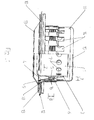
- Fig. 1 shows a gas generator 1, which in a recess in the airbag is housed in a known manner. From the gas generator 1 is only the filter tube 2 shown without fuel and closure. The Filter tube 2 forms the outer wall 3 of the gas generator 1 Membrane 4 is the outer wall 3 of the gas generator 1 with the no closer drawn airbag housing connected. Attaching the membrane 4 on the outer wall 3 of the gas generator 1 takes place via the upper edge 5 the membrane 4, which in the present example is in the form of a ring 6, is trained. This ring 6 is made by reinforcing the wall thickness 7 of the partial area 8 of the membrane 4, with which the membrane 4 is directly attached the wall 3 is attached. The lower edge 9 of the membrane 4 is with a Fastening plate 10 connected.
- the membrane 4 can, for example, in the same Strength are maintained and their top edge 5 in a cylindrical shape available. However, training as a reinforced ring 6 is cheaper thereby a better fastening of the membrane 4 on the outer wall 3 can be carried out by vulcanization.
- the ring 6 be provided with the protruding ridges 16 which are excessive large deflections of the gas generator 1 serve as a stop damper can, if they come to rest on the wall of the sheet 11.
- the in Diffuser 2 contained holes 17 are the outlet openings for the at one Triggering of the gas generator resulting gases.
- the filter tube 2 which forms the gas generator wall 3, again shown partly in view and in section.
- the gas generator wall 3 is on the Junction 8 for the membrane 4 with one to the outside projecting annular bead 20 provided.
- This ring bead 20 facilitates the Attaching the ring 6 of the membrane 4 to the gas generator wall 3.
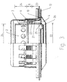
- FIG. 3 Another embodiment of the filter tube 2 and the connection with the Membrane 4 is shown in FIG. 3.
- the membrane 4, the ring 6 and the cover 21 are one unit and consist of the same Material. You will be in one vulcanization step with the Gas generator wall 3 and the mounting plate 10 connected.
- the cover 21 at its lower end 25 provided with the edge bead 26, which acts as a stop damping for axial Movements on the bottom plate 13 is used.
- FIG. 4 shows an embodiment in section, in which a filter tube 2 is shown, to which a membrane 30 is attached, which is distributed over its circumference and provided with reinforcing webs 31 running along the membrane 30.
- the membrane 30 is provided with the best fastening plate 10 at its lower end.
- the membrane 30 can also be provided with stop-damping projections.
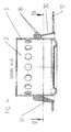
- FIG. 5 shows a section along line BB of FIG. 4.
- the approximately square shape of the fastening plate 10 with the openings 35 for the fastening screws or rivets, the membrane 30 with the reinforcing webs 31 and the gas generator wall 3 can be seen.
- FIG. 6 shows an embodiment of the membrane 4 in which the membrane 4 with the smaller diameter of the truncated cone is oriented downward.
- the ring 6 is here at the lower end of the membrane 4 and the mounting plate 10 at the upper end.
- the mounting ring 6 is attached directly to the gas generator wall 3.
- the filter tube 2 and also all other parts are identical to the embodiment according to FIG. 1.
Landscapes
- Engineering & Computer Science (AREA)
- Mechanical Engineering (AREA)
- Air Bags (AREA)
Abstract
Description
- Fig. 1
- den Gasgenerator teilweise im Längsschnitt untergebracht in einem Diffusor.
- Fig. 2
- einen Gasgenerator mit einer Ringwulst in der Gasgeneratorwand,
- Fig. 3
- einen Gasgenerator teilweise im Längsschnitt mit einem Überzug unterhalb der Verbindungsstelle.
- Fig. 4
- einen Gasgenerator teilweise im Längsschnitt mit einer Membran mit Verstärkungsrippen.
- Fig. 5
- eine Draufsicht auf den Gasgenerator nach Fig. 4 und
- Fig. 6
- eine weitere Ausführungsform eines Gasgenerators mit Haltemembran teilweise im Längsschnitt.
Der Vollständigkeit halber zeigt die Fig. 6 eine Ausführungsform der Membran 4, bei der die Membran 4 mit dem kleineren Durchmesser des Kegelstumpfs nach unten ausgerichtet ist. Der Ring 6 befindet sich hier am unteren Ende der Membran 4 und das Befestigungsblech 10 am oberen Ende. Der Befestigungsring 6 ist direkt an der Gasgeneratorwand 3 befestigt. Das Filterrohr 2 und auch alle anderen Teile sind identisch mit der Ausführungsform nach der Fig. 1.
Claims (13)
- Gasgenerator für einen Airbag an einem Kraftfahrzeug-Lenkrad, der beweglich als Schwingungsdämpfermasse über eine gasundurchlässige, ringförmige Membran aus polymerem Material und ein an einem ihrer Ränder angebrachtes Befestigungsblech mit dem Airbaggehäuse verbunden ist, dadurch gekennzeichnet, dass die Membran (4,30) mit ihrem verbliebenen anderen Rand (5) direkt an die Außenwand (3) des Gasgenerators (1) anschließt.
- Gasgenerator nach Anspruch 1, dadurch gekennzeichnet, dass die Membran (4) kegelstumpfförmig ausgebildet ist.
- Gasgenerator nach Anspruch 1 oder 2, dadurch gekennzeichnet, dass die Membran (4) über einen für die Verbindung mit der Gasgeneratoraußenwand (3) verwendeten Teilbereich (8) auf ihrer Innenseite zylindrisch ausgebildet ist.
- Gasgenerator nach einem der Ansprüche 1 bis 3 dadurch gekennzeichnet, dass der Teilbereich (8) der Membran (4) eine verstärkte Wanddicke (7) und die Form eines Ringes (6) hat.
- Gasgenerator nach einem der Ansprüche 1 bis 4, dadurch gekennzeichnet, dass der Gasgenerator (1) von einem Airbagabstandsblech (11) zumindest teilweise überdeckt ist.
- Gasgenerator nach einem der Ansprüche 1 bis 5, dadurch gekennzeichnet, dass die Außenseite des Ringes (6) mit Anschläge dämpfenden Vorsprüngen (16) versehen ist.
- Gasgenerator nach einem der Ansprüche 1 bis 6, dadurch gekennzeichnet, dass die Verbindung zwischen der Membran (4) und der Gasgeneratorwand (3) durch Vulkanisation hergestellt ist.
- Gasgenerator nach einem der Ansprüche 1 bis 7, dadurch gekennzeichnet, dass die Gasgeneratorwand (3) an der Verbindungsstelle (8) für die Membran (4) mit einer nach außen hervorstehenden Ringwulst (20) versehen ist.
- Gasgenerator nach einem der Ansprüche 1 bis 8, dadurch gekennzeichnet, dass die Gasgeneratorwand (3) unterhalb der Verbindungsstelle (8) für die Membran (4) einen Überzug (21) aus polymerem Material hat.
- Gasgenerator nach .einem der Ansprüche 1 bis 9, dadurch gekennzeichnet, dass Membran (4), Ring (6) und Überzug (21) aus dem gleichen Material bestehen und in einem Vulkanisationsschritt mit der Gasgeneratorwand (3) und dem Befestigungsblech (10) verbunden sind.
- Gasgenerator nach einem der Ansprüche 1 bis 10, dadurch gekennzeichnet, dass die Gasgeneratorwand (3) im Anschlussbereich (8) für den Ring (6) und im Bereich (23) des Überzugs (21) einen größeren Durchmesser (22) hat als der darüberliegende Bereich (24) der Gasgeneratorwand (3).
- Gasgenerator nach einem der Ansprüche 1 bis 11, dadurch gekennzeichnet, dass der Überzug (21) an seinem unteren Ende (25) eine Anschläge dämpfende Randwulst (26) hat.
- Gasgenerator nach einem der Ansprüche 1 bis 12, dadurch gekennzeichnet, dass die Membran (30) auf ihrem Umfang verteilt mehrere längs der Membran (30) verlaufende Verstärkungsstege (31) hat.
Applications Claiming Priority (2)
| Application Number | Priority Date | Filing Date | Title |
|---|---|---|---|
| DE10013472 | 2000-03-18 | ||
| DE2000113472 DE10013472C2 (de) | 2000-03-18 | 2000-03-18 | Gasgenerator für einen Airbag an einem Kraftfahrzeug-Lenkrad |
Publications (2)
| Publication Number | Publication Date |
|---|---|
| EP1136328A2 true EP1136328A2 (de) | 2001-09-26 |
| EP1136328A3 EP1136328A3 (de) | 2003-03-26 |
Family
ID=7635417
Family Applications (1)
| Application Number | Title | Priority Date | Filing Date |
|---|---|---|---|
| EP00126335A Withdrawn EP1136328A3 (de) | 2000-03-18 | 2000-12-02 | Lenkrad- Airbagmodul mit einem Gasgenerator als Schwingungsdämpfermasse |
Country Status (2)
| Country | Link |
|---|---|
| EP (1) | EP1136328A3 (de) |
| DE (1) | DE10013472C2 (de) |
Cited By (6)
| Publication number | Priority date | Publication date | Assignee | Title |
|---|---|---|---|---|
| US7144034B2 (en) | 2004-02-18 | 2006-12-05 | Autoliv Asp, Inc. | Vibration damper gasket |
| US7374199B2 (en) | 2005-04-04 | 2008-05-20 | Arc Automotive, Inc. | Air bag inflator vibration damper |
| US7494150B2 (en) | 2006-04-05 | 2009-02-24 | Arc Automotive, Inc. | Air bag inflator vibration damper |
| CN101643056B (zh) * | 2008-08-06 | 2011-12-28 | 三菱自动车工业株式会社 | 安全气囊装置 |
| EP2995512A1 (de) * | 2014-09-11 | 2016-03-16 | Dalphi Metal España, S.A. | Airbagmodul, Halter und Anordnung eines Airbagmoduls und Lenkrad |
| US20230085416A1 (en) * | 2020-01-22 | 2023-03-16 | Vibracoustic Se | Vibration damper for a vehicle steering wheel |
Families Citing this family (2)
| Publication number | Priority date | Publication date | Assignee | Title |
|---|---|---|---|---|
| DE102007049234B4 (de) * | 2007-10-10 | 2014-12-04 | TAKATA Aktiengesellschaft | Airbagmodul für ein Kraftfahrzeug |
| DE202008013900U1 (de) * | 2008-08-04 | 2009-12-31 | Trw Airbag Systems Gmbh | Gassackmodul |
Citations (1)
| Publication number | Priority date | Publication date | Assignee | Title |
|---|---|---|---|---|
| DE3925761A1 (de) | 1988-08-08 | 1990-02-15 | Honda Motor Co Ltd | Vibrationsunterdrueckungsvorrichtung fuer ein lenkrad mit einem luftsack |
Family Cites Families (9)
| Publication number | Priority date | Publication date | Assignee | Title |
|---|---|---|---|---|
| JPH04143143A (ja) * | 1990-10-02 | 1992-05-18 | Nissan Motor Co Ltd | 車両用エアバッグ装置 |
| DE4205726C3 (de) * | 1991-02-25 | 1999-04-29 | Trw Inc | Fahrzeuggassackmodul mit Koppelvorrichtung |
| DE4447610C2 (de) * | 1994-09-06 | 1997-06-12 | Clouth Gummiwerke Ag | Schwingungstilger |
| JPH0986418A (ja) * | 1995-09-22 | 1997-03-31 | Nippon Plast Co Ltd | ステアリングホイールの振動抑制装置 |
| DE29816923U1 (de) * | 1998-09-16 | 1998-11-26 | Petri Ag, 63743 Aschaffenburg | Lenkrad mit Airbagmodul |
| DE29816925U1 (de) * | 1998-09-16 | 1998-11-26 | Petri Ag, 63743 Aschaffenburg | Lenkrad mit Airbagmodul |
| DE19858691B4 (de) * | 1998-12-18 | 2010-01-07 | Delphi Automotive Systems Deutschland Gmbh | Luftsackmodul für Kraftfahrzeuge |
| DE29902033U1 (de) * | 1999-02-05 | 1999-04-08 | TRW Automotive Safety Systems GmbH, 63743 Aschaffenburg | Airbagmodul als Schwingungsdämpfer |
| DE19908915B4 (de) * | 1999-03-02 | 2007-04-05 | Carl Freudenberg Kg | Schwingungstilger für ein Lenkrad mit einem Airbag |
-
2000
- 2000-03-18 DE DE2000113472 patent/DE10013472C2/de not_active Expired - Fee Related
- 2000-12-02 EP EP00126335A patent/EP1136328A3/de not_active Withdrawn
Patent Citations (1)
| Publication number | Priority date | Publication date | Assignee | Title |
|---|---|---|---|---|
| DE3925761A1 (de) | 1988-08-08 | 1990-02-15 | Honda Motor Co Ltd | Vibrationsunterdrueckungsvorrichtung fuer ein lenkrad mit einem luftsack |
Cited By (6)
| Publication number | Priority date | Publication date | Assignee | Title |
|---|---|---|---|---|
| US7144034B2 (en) | 2004-02-18 | 2006-12-05 | Autoliv Asp, Inc. | Vibration damper gasket |
| US7374199B2 (en) | 2005-04-04 | 2008-05-20 | Arc Automotive, Inc. | Air bag inflator vibration damper |
| US7494150B2 (en) | 2006-04-05 | 2009-02-24 | Arc Automotive, Inc. | Air bag inflator vibration damper |
| CN101643056B (zh) * | 2008-08-06 | 2011-12-28 | 三菱自动车工业株式会社 | 安全气囊装置 |
| EP2995512A1 (de) * | 2014-09-11 | 2016-03-16 | Dalphi Metal España, S.A. | Airbagmodul, Halter und Anordnung eines Airbagmoduls und Lenkrad |
| US20230085416A1 (en) * | 2020-01-22 | 2023-03-16 | Vibracoustic Se | Vibration damper for a vehicle steering wheel |
Also Published As
| Publication number | Publication date |
|---|---|
| EP1136328A3 (de) | 2003-03-26 |
| DE10013472C2 (de) | 2002-12-19 |
| DE10013472A1 (de) | 2002-08-08 |
Similar Documents
| Publication | Publication Date | Title |
|---|---|---|
| EP1113948B2 (de) | Lenkrad mit airbagmodul | |
| DE3011906C2 (de) | Stoßfänger für Fahrzeuge | |
| EP1101663A2 (de) | Als Schwingungsdämpfermasse wirkender Gasgenerator | |
| EP1020332A2 (de) | Luftsackmodul für Kraftfahrzeuge | |
| EP1026050A2 (de) | Airbagmodul als Schwingungsdämpfer | |
| DE3925761A1 (de) | Vibrationsunterdrueckungsvorrichtung fuer ein lenkrad mit einem luftsack | |
| DE102009006077B4 (de) | Gassackeinheit | |
| EP1113950A1 (de) | Lenkrad mit airbagmodul | |
| EP0612944A1 (de) | Einteiliges Halteelement | |
| DE19908915B4 (de) | Schwingungstilger für ein Lenkrad mit einem Airbag | |
| DE10156424B4 (de) | Luftsackmodul für Kraftfahrzeuge | |
| DE10013472C2 (de) | Gasgenerator für einen Airbag an einem Kraftfahrzeug-Lenkrad | |
| EP2251218A1 (de) | Gelenkiges Stützlager | |
| DE112019004227T5 (de) | Halterungselement | |
| DE2553822C2 (de) | ||
| DE10110912B4 (de) | Airbagmodul für ein Lenkrad eines Kraftfahrzeugs | |
| DE10002480B4 (de) | Airbagmodul für ein Kraftfahrzeuglenkrad | |
| DE102012004866A1 (de) | Airbagmodul für ein Kraftfarzeuglenkrad | |
| EP1101662A2 (de) | Lenkrad schwingungstilgender wirkender Airbaggasgenerator | |
| DE102010046118B4 (de) | Kupplungsteil für eine Drei- oder Mehrstellenanbindung und Drei- oder Mehrstellenanbindung | |
| EP1238869A1 (de) | Gasgenerator für einen Airbag am Lenkrad eines Kraftfahrzeuges | |
| DE10222875A1 (de) | Hydraulisch gedämpfte Montagevorrichtung | |
| DE102017119335A1 (de) | Gassackmodul für ein fahrzeuglenkrad | |
| DE7823305U1 (de) | Aufhängung für Automobile | |
| EP1273488B1 (de) | Gasgenerator für einen Lenkradairbag |
Legal Events
| Date | Code | Title | Description |
|---|---|---|---|
| PUAI | Public reference made under article 153(3) epc to a published international application that has entered the european phase |
Free format text: ORIGINAL CODE: 0009012 |
|
| AK | Designated contracting states |
Kind code of ref document: A2 Designated state(s): AT BE CH CY DE DK ES FI FR GB GR IE IT LI LU MC NL PT SE TR |
|
| AX | Request for extension of the european patent |
Free format text: AL;LT;LV;MK;RO;SI |
|
| RAP1 | Party data changed (applicant data changed or rights of an application transferred) |
Owner name: CARL FREUDENBERG KG |
|
| PUAL | Search report despatched |
Free format text: ORIGINAL CODE: 0009013 |
|
| AK | Designated contracting states |
Kind code of ref document: A3 Designated state(s): AT BE CH CY DE DK ES FI FR GB GR IE IT LI LU MC NL PT SE TR Designated state(s): AT BE CH CY DE DK ES FI FR GB GR IE IT LI LU MC NL PT SE TR |
|
| AX | Request for extension of the european patent |
Extension state: AL LT LV MK RO SI |
|
| RIC1 | Information provided on ipc code assigned before grant |
Ipc: 7B 62D 7/22 B Ipc: 7B 60R 21/20 A |
|
| 17P | Request for examination filed |
Effective date: 20030220 |
|
| AKX | Designation fees paid |
Designated state(s): DE FR PT |
|
| GRAP | Despatch of communication of intention to grant a patent |
Free format text: ORIGINAL CODE: EPIDOSNIGR1 |
|
| STAA | Information on the status of an ep patent application or granted ep patent |
Free format text: STATUS: THE APPLICATION IS DEEMED TO BE WITHDRAWN |
|
| 18D | Application deemed to be withdrawn |
Effective date: 20040603 |