EP2251218A1 - Gelenkiges Stützlager - Google Patents
Gelenkiges Stützlager Download PDFInfo
- Publication number
- EP2251218A1 EP2251218A1 EP10002410A EP10002410A EP2251218A1 EP 2251218 A1 EP2251218 A1 EP 2251218A1 EP 10002410 A EP10002410 A EP 10002410A EP 10002410 A EP10002410 A EP 10002410A EP 2251218 A1 EP2251218 A1 EP 2251218A1
- Authority
- EP
- European Patent Office
- Prior art keywords
- support bearing
- bearing according
- support plate
- articulated support
- articulated
- Prior art date
- Legal status (The legal status is an assumption and is not a legal conclusion. Google has not performed a legal analysis and makes no representation as to the accuracy of the status listed.)
- Withdrawn
Links
- 229920001971 elastomer Polymers 0.000 claims abstract description 16
- 239000000806 elastomer Substances 0.000 claims abstract description 16
- 239000002184 metal Substances 0.000 claims abstract description 3
- 238000005096 rolling process Methods 0.000 claims description 5
- 230000035939 shock Effects 0.000 description 5
- 239000006096 absorbing agent Substances 0.000 description 4
- 238000004519 manufacturing process Methods 0.000 description 3
- 239000000725 suspension Substances 0.000 description 2
- 229910000831 Steel Inorganic materials 0.000 description 1
- 230000015572 biosynthetic process Effects 0.000 description 1
- 238000010276 construction Methods 0.000 description 1
- 238000002788 crimping Methods 0.000 description 1
- 238000009434 installation Methods 0.000 description 1
- 238000000034 method Methods 0.000 description 1
- 238000007789 sealing Methods 0.000 description 1
- 239000010959 steel Substances 0.000 description 1
Images

Classifications
-
- B—PERFORMING OPERATIONS; TRANSPORTING
- B60—VEHICLES IN GENERAL
- B60G—VEHICLE SUSPENSION ARRANGEMENTS
- B60G13/00—Resilient suspensions characterised by arrangement, location or type of vibration dampers
- B60G13/001—Arrangements for attachment of dampers
- B60G13/003—Arrangements for attachment of dampers characterised by the mounting on the vehicle body or chassis of the damper unit
-
- B—PERFORMING OPERATIONS; TRANSPORTING
- B60—VEHICLES IN GENERAL
- B60G—VEHICLE SUSPENSION ARRANGEMENTS
- B60G15/00—Resilient suspensions characterised by arrangement, location or type of combined spring and vibration damper, e.g. telescopic type
- B60G15/02—Resilient suspensions characterised by arrangement, location or type of combined spring and vibration damper, e.g. telescopic type having mechanical spring
- B60G15/06—Resilient suspensions characterised by arrangement, location or type of combined spring and vibration damper, e.g. telescopic type having mechanical spring and fluid damper
- B60G15/067—Resilient suspensions characterised by arrangement, location or type of combined spring and vibration damper, e.g. telescopic type having mechanical spring and fluid damper characterised by the mounting on the vehicle body or chassis of the spring and damper unit
- B60G15/068—Resilient suspensions characterised by arrangement, location or type of combined spring and vibration damper, e.g. telescopic type having mechanical spring and fluid damper characterised by the mounting on the vehicle body or chassis of the spring and damper unit specially adapted for MacPherson strut-type suspension
-
- B—PERFORMING OPERATIONS; TRANSPORTING
- B60—VEHICLES IN GENERAL
- B60G—VEHICLE SUSPENSION ARRANGEMENTS
- B60G15/00—Resilient suspensions characterised by arrangement, location or type of combined spring and vibration damper, e.g. telescopic type
- B60G15/08—Resilient suspensions characterised by arrangement, location or type of combined spring and vibration damper, e.g. telescopic type having fluid spring
- B60G15/12—Resilient suspensions characterised by arrangement, location or type of combined spring and vibration damper, e.g. telescopic type having fluid spring and fluid damper
-
- F—MECHANICAL ENGINEERING; LIGHTING; HEATING; WEAPONS; BLASTING
- F16—ENGINEERING ELEMENTS AND UNITS; GENERAL MEASURES FOR PRODUCING AND MAINTAINING EFFECTIVE FUNCTIONING OF MACHINES OR INSTALLATIONS; THERMAL INSULATION IN GENERAL
- F16F—SPRINGS; SHOCK-ABSORBERS; MEANS FOR DAMPING VIBRATION
- F16F1/00—Springs
- F16F1/36—Springs made of rubber or other material having high internal friction, e.g. thermoplastic elastomers
- F16F1/373—Springs made of rubber or other material having high internal friction, e.g. thermoplastic elastomers characterised by having a particular shape
- F16F1/3732—Springs made of rubber or other material having high internal friction, e.g. thermoplastic elastomers characterised by having a particular shape having an annular or the like shape, e.g. grommet-type resilient mountings
-
- F—MECHANICAL ENGINEERING; LIGHTING; HEATING; WEAPONS; BLASTING
- F16—ENGINEERING ELEMENTS AND UNITS; GENERAL MEASURES FOR PRODUCING AND MAINTAINING EFFECTIVE FUNCTIONING OF MACHINES OR INSTALLATIONS; THERMAL INSULATION IN GENERAL
- F16F—SPRINGS; SHOCK-ABSORBERS; MEANS FOR DAMPING VIBRATION
- F16F9/00—Springs, vibration-dampers, shock-absorbers, or similarly-constructed movement-dampers using a fluid or the equivalent as damping medium
- F16F9/32—Details
- F16F9/54—Arrangements for attachment
-
- B—PERFORMING OPERATIONS; TRANSPORTING
- B60—VEHICLES IN GENERAL
- B60G—VEHICLE SUSPENSION ARRANGEMENTS
- B60G2202/00—Indexing codes relating to the type of spring, damper or actuator
- B60G2202/30—Spring/Damper and/or actuator Units
- B60G2202/31—Spring/Damper and/or actuator Units with the spring arranged around the damper, e.g. MacPherson strut
-
- B—PERFORMING OPERATIONS; TRANSPORTING
- B60—VEHICLES IN GENERAL
- B60G—VEHICLE SUSPENSION ARRANGEMENTS
- B60G2204/00—Indexing codes related to suspensions per se or to auxiliary parts
- B60G2204/10—Mounting of suspension elements
- B60G2204/12—Mounting of springs or dampers
- B60G2204/126—Mounting of pneumatic springs
- B60G2204/1262—Mounting of pneumatic springs on a damper
-
- B—PERFORMING OPERATIONS; TRANSPORTING
- B60—VEHICLES IN GENERAL
- B60G—VEHICLE SUSPENSION ARRANGEMENTS
- B60G2204/00—Indexing codes related to suspensions per se or to auxiliary parts
- B60G2204/10—Mounting of suspension elements
- B60G2204/12—Mounting of springs or dampers
- B60G2204/128—Damper mount on vehicle body or chassis
-
- B—PERFORMING OPERATIONS; TRANSPORTING
- B60—VEHICLES IN GENERAL
- B60G—VEHICLE SUSPENSION ARRANGEMENTS
- B60G2204/00—Indexing codes related to suspensions per se or to auxiliary parts
- B60G2204/40—Auxiliary suspension parts; Adjustment of suspensions
- B60G2204/45—Stops limiting travel
- B60G2204/4502—Stops limiting travel using resilient buffer
-
- B—PERFORMING OPERATIONS; TRANSPORTING
- B60—VEHICLES IN GENERAL
- B60G—VEHICLE SUSPENSION ARRANGEMENTS
- B60G2204/00—Indexing codes related to suspensions per se or to auxiliary parts
- B60G2204/40—Auxiliary suspension parts; Adjustment of suspensions
- B60G2204/46—Means for locking the suspension
- B60G2204/4602—Locking of a McPerson type strut upper mount on the vehicle body
-
- F—MECHANICAL ENGINEERING; LIGHTING; HEATING; WEAPONS; BLASTING
- F16—ENGINEERING ELEMENTS AND UNITS; GENERAL MEASURES FOR PRODUCING AND MAINTAINING EFFECTIVE FUNCTIONING OF MACHINES OR INSTALLATIONS; THERMAL INSULATION IN GENERAL
- F16F—SPRINGS; SHOCK-ABSORBERS; MEANS FOR DAMPING VIBRATION
- F16F2230/00—Purpose; Design features
- F16F2230/02—Surface features, e.g. notches or protuberances
Definitions
- the present invention relates to an articulated support bearing, in particular for suspension struts for motor vehicles with an elastically enclosed support plate for the connection of the piston rod of the vibration damper to a support part of the motor vehicle,
- the support bearings used here must allow pivotal movements of the piston rod and also absorb the forces acting axially on the piston rod.
- the support plate is connected to an elastomer element which is designed in the axial, radial and gimbal direction with a predetermined spring stiffness.
- an articulated support bearing in which the piston rod is fastened to a support plate, wherein the support plate is enclosed on both sides by an elastomer element.
- the support plate is vulcanized into the elastomer body, while the other possibility provides, the to connect with shock struts usual pressure stop with the support plate, which in turn rests on the elastomer element.
- the elastomeric element in turn consists of two superposed halves, which come to rest on the top sides of a support disk.
- the support disk itself serves to connect the shock absorber to a motor vehicle part.
- the production of such a support bearing has both manufacturing and assembly moderate the disadvantage that it is associated with high costs.
- the invention has for its object to provide a support bearing, which is simple in its structural design and its manufacture including assembly with a few steps is feasible.
- the support bearing according to the invention holds the support plate which is connected via the threaded pin on the piston rod with the same.
- the attachment of the support plate on the connection part of the shock absorber is made via elastomer elements, which border the support plate and which in turn are fastened to the connection part of the shock absorber.
- the support plate itself is made of metal and has a central, the threaded pin of the piston rod comprehensive opening so that it can be placed on the threaded pin. It is advantageous if between the support plate and the threaded neck on the piston rod, an adapter ring is used over which the stability of the support plate is improved by having a larger outer radius than the piston rod itself equipped, an enlarged Support surface forms for the support plate. In addition, it is advantageous if the adapter ring has an axially projecting inner collar, on which the support plate can be fixedly placed and caulked.
- the support plate is provided with a sheath made of plastic. It is advantageous if the casing on the support plate leaves a free space for the adapter ring and a fastening nut. Moreover, it is advantageous if the support plate is provided on its circumference with openings, which result in an improved mounting of the plastic sheath on the support plate.
- the preferred embodiment of the invention provides that two symmetrical elastomer elements are used in the form of half-shells.
- the elastomeric elements are provided in their interior with an annular groove, which is adapted to the shape of the support plate, so that the support plate is bordered by the elastomeric elements edge.
- the axial end faces on the mounting joint of the half-shells come to each other during installation to the concern and thus provide a tight seal at the joints.
- the elastomer elements may be provided on their top and / or bottom with protruding humps, which support the spring process.
- the support member is provided for the connection of the support bearing on the motor vehicle with a housing for the support bearing.
- This housing has a bottom opening through which the piston rod of the vibration damper is passed.
- the housing is sealed with a lid. Between the bottom of the housing and its lid, the elastomeric elements are clamped in the housing.
- the design of the shock absorber itself can be per se conventional design, for example, a gas spring is used for the spring action, which is provided with a bellows and a corresponding piston for the unrolling of the Federbalgs.
- the housing of its underside is equipped with a stop buffer.
- FIG. 1 is shown in longitudinal section, the housing 1 with the support bearing 2 therein for the connection of the piston rod 3. All parts belong to a strut used in motor vehicles.
- the piston rod 3 is part of the vibration damper, which cooperates in the present case with a gas spring, and with a rolling bellows on a Rolling piston rolls off. These parts of the strut are not shown in detail, since they can be conventional construction.
- the articulated support bearing 2 has the support plate 4, which is bordered by two elastomer elements 5.
- the elastomer elements 5 are formed as symmetrical half shells.
- the longitudinal section shown in the figure by the support bearing 2 is guided at the axial joints 6 of the half-shells, so that in the figure, the joints 6 of the rear half-shell 7 are visible.
- the support plate 4 is made of a steel sheet to accommodate the high of the piston rod 3 outgoing forces.
- the threaded pin 8 of the piston rod 3 is guided by the present in the support plate 4 opening 9 and the support plate 4 screwed on the nut 10.
- an adapter ring 12 is inserted between the threaded extension 11 on the piston rod 3 and the support plate 4, which results in a larger support surface 13 for the support plate 4 relative to the threaded extension 11.
- the adapter ring 12 has the inner collar 15 which is inserted and caulked fit into the opening 9 of the support plate 4.
- the present in the form of an annular disk support plate 4 is provided with the existing plastic sheath 16.
- This casing 16 comprises the support plate 4 from the outer edges forth and has in the inner region of the free space 17 for the adapter ring 12 and the fastening nut 10. The latter two parts can thereby act directly on the support plate 4.
- the support plate 4 is provided with the openings 18 which are penetrated by the plastic.
- the openings 18 are attached to the support plate 4 at predetermined intervals.
- the elastomeric elements 5 may be provided on their top and bottom with the protruding humps 20.
- the bumps 20 are spaced apart by radially aligned grooves 21.
- the bumps 20 are co-determining the suspension behavior of the support bearing 2.
- the elastomeric elements 5 have the inner annular grooves 23 which form-fit the plastic jacket 16 with the support plate 4.
- the Housing 1 is provided with the receiving chamber 24, in which the support bearing 2 is inserted properly.
- the receiving chamber 24 has the bottom opening 25 for the passage of the piston rod 3. This opening 25 allows the gimbal movement of the piston rod 3 to.
- the receiving chamber 24 is sealed to the lid 26.
- the lid 26 is held by the crimping edge 27 of the housing 1 in its position.
- At the bottom 28 of the receiving chamber 24 of the stop buffer 29 is mounted for the rolling piston of the gas spring.
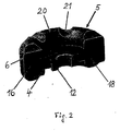
- FIG. 2 is a perspective view of an elastomeric element 5 with befindaji support plate 4 and adapter ring 12 is shown.
- the elastomer element 5 is shown in the form of a half-shell and the parts enclosed therein of support plate 4 and adapter ring 12 are cut in the region of the mounting joint.
- the surfaces 6 of the mounting joint come after mounting the support bearing 2 in the receiving chamber 24 with the corresponding surfaces of the opposite half-shell sealing to the plant.
- the bumps 20 of the elastomer element 5 are clearly visible.
Landscapes
- Engineering & Computer Science (AREA)
- Mechanical Engineering (AREA)
- General Engineering & Computer Science (AREA)
- Vehicle Body Suspensions (AREA)
- Fluid-Damping Devices (AREA)
Abstract
Gelenkiges Stützlager insbesondere bei Federbeinen für Kraftfahrzeuge, mit einer elastisch eingefassten Tragplatte für die Anbindung der Kolbenstange des Schwingungsdämpfers an einem Stützteil am Kraftfahrzeug, wobei die Tragplatte (4) von mindestens zwei einzelnen Elastomerelementen (5) randseitig eingefasst ist.
Description
- Die vorliegende Erfindung betrifft ein gelenkiges Stützlager, insbesondere bei Federbeinen für Kraftfahrzeuge mit einer elastisch eingefassten Tragplatte für die Anbindung der Kolbenstange des Schwingungsdämpfers an einem Stützteil des Kraftfahrzeugs,
- Die hier zum Einsatz kommenden Stützlager müssen Schwenkbewegungen der Kolbenstange zulassen und außerdem die axial auf die Kolbenstange einwirkenden Kräfte abfangen. Zu diesem Zweck wird die Tragplatte mit einem Elastomerelement verbunden, welches in axialer, radialer und kardanischer Richtung mit einer vorher festgelegten Federsteifigkeit ausgelegt wird.
- Aus der
DE 197 55 549 A1 ist die Ausbildung eines gelenkigen Stützlagers bekannt, bei dem die Kolbenstange an einer Tragplatte befestigt wird, wobei die Tragplatte beidseitig von einem Elastomerelement eingefasst ist. Dabei werden zwei Möglichkeiten angegeben. Zum einen wird die Tragplatte in den Elastomerkörper einvulkanisiert, während die andere Möglichkeit vorsieht, den bei Federbeinen üblichen Druckanschlag mit der Tragplatte zu verbinden, die ihrerseits am Elastomerelement anliegt. Das Elastomerelement seinerseits besteht aus zwei übereinander liegenden Hälften, die auf den Deckseiten einer Abstützscheibe zur Anlage kommen. Die Abstützscheibe selbst dient zur Verbindung des Federbeins mit einem Kraftfahrzeugteil. Die Herstellung eines solchen Stützlagers hat sowohl fertigungs- als auch montagemäßig den Nachteil, dass es mit hohem Aufwand verbunden ist. - Der Erfindung liegt die Aufgabe zugrunde, ein Stützlager zu schaffen, welches einfach in seinem konstruktiven Aufbau ist und dessen Herstellung einschließlich Montage mit wenigen Verfahrensschritten durchführbar ist.
- Die Lösung der gestellten Aufgabe wird mit den Merkmalen des Anspruchs 1 durchgeführt.
- Das erfindungsgemäße Stützlager hält die Tragplatte wobei diese über den Gewindezapfen an der Kolbenstange mit derselben verbunden wird. Die Anbringung der Tragplatte am Anbindungsteil des Federbeins wird über Elastomerelemente vorgenommen, welche randseitig die Tragplatte einfassen und die ihrerseits am Anbindungsteil des Federbeins befestigt sind.
- Die Tragplatte selbst ist aus Metall und hat eine zentrale, den Gewindezapfen der Kolbenstange umfassende Öffnung, so dass sie auf den Gewindezapfen aufgesetzt werden kann. Von Vorteil ist, wenn zwischen die Tragplatte und dem Gewindeansatz an der Kolbenstange ein Adapterring eingesetzt wird, über den die Standfestigkeit der Tragplatte verbessert wird, indem er mit einem größeren Außenradius als die Kolbenstange selbst ausgestattet, eine vergrößerte Auflagefläche für die Tragplatte bildet. Außerdem ist es günstig, wenn der Adapterring einen axial vorstehenden Innenkragen hat, auf den die Tragplatte ortsfest aufgesetzt und verstemmt werden kann.
- Bevorzugt wird die Tragplatte mit einer Ummantelung aus Kunststoff versehen. Dabei ist es günstig, wenn die Ummantelung an der Tragplatte einen Freiraum für den Adapterring und eine Befestigungsmutter frei lässt. Darüber hinaus ist es von Vorteil, wenn die Tragplatte auf ihrem Umfang mit Öffnungen versehen wird, die einer verbesserten Halterung der Kunststoffummantelung an der Tragplatte ergeben.
- Die bevorzugte Ausführungsform der Erfindung sieht vor, dass zwei symmetrisch ausgebildete Elastomerelemente in Form von Halbschalen verwendet werden. Die Elastomerelemente sind in ihrem Inneren mit einer ringförmigen Nut versehen, die an die Form der Tragplatte angepasst ist, so dass die Tragplatte von den Elastomerelementen randseitig eingefasst wird. Die axialen Stirnflächen am Montagestoß der Halbschalen kommen bei der Montage aneinander zum Anliegen und ergeben dadurch einen dichten Abschluss an den Stoßstellen. Um eine gute Abfederung des Stützlagers in axialer Richtung zu erreichen, können die Elastomerelemente auf ihrer Ober- und/oder Unterseite mit hervorstehenden Höckern versehen sein, welche den Federvorgang unterstützen.
- Zur besonders einfachen Ausbildung des Stützlagers trägt auch bei, dass das Stützteil für die Anbindung des Stützlagers am Kraftfahrzeug mit einem Gehäuse für das Stützlager versehen wird. Dieses Gehäuse hat eine Bodenöffnung, durch welche die Kolbenstange des Schwingungsdämpfers hindurchgeführt wird. Auf der gegenüber liegenden Seite ist das Gehäuse mit einem Deckel dicht verschlossen. Zwischen dem Boden des Gehäuses und seinem Deckel werden die Elastomerelemente im Gehäuse festgeklemmt. Die Ausbildung des Federbeins selbst kann an sich üblicher Bauweise sein, indem für den Federvorgang z.B. eine Gasfeder eingesetzt wird, welche mit einem Federbalg und einem entsprechenden Kolben für das Abrollen des Federbalgs versehen ist. Zur Begrenzung des Federwegs des Abrollkolbens ist das Gehäuse seiner Unterseite mit einem Anschlagpuffer ausgestattet.
- Anhand eines in der Zeichnung dargestellten Ausführungsbeispiels wird die Erfindung nachstehend näher erläutert.
Es zeigt - Fig. 1
- einen Längsschnitt durch das in ein Stützteil eines Kraftfahrzeugs eingebaut Stützlager und
- Fig. 2
- eine perspektivische Ansicht eines als Halbschale ausgebildeten Elastomerelements mit eingefügter Tragplatte und Adapterring im Schnitt gesehen.
- In der
Figur 1 ist im Längsschnitt das Gehäuse 1 mit dem darin befindlichen Stützlager 2 für die Anbindung der Kolbenstange 3 dargestellt. Alle Teile gehören zu einem bei Kraftfahrzeugen eingesetzten Federbein. Die Kolbenstange 3 ist Teil des Schwingungsdämpfers, der im vorliegenden Fall mit einer Gasfeder zusammen wirkt, die und mit einem Rollbalg an einem Rollkolben abrollt. Diese Teile des Federbeins sind nicht näher dargestellt, da sie üblicher Bauweise sein können. Das gelenkig ausgebildete Stützlager 2 hat die Tragplatte 4, die von zwei Elastomerelementen 5 eingefasst ist Die Elastomerelemente 5 sind als symmetrische Halbschalen ausgebildet. Der in der Figur gezeigte Längsschnitt durch das Stützlager 2 ist an den axialen Stoßstellen 6 der Halbschalen geführt, so dass in der Figur die Stoßstellen 6 der rückwärtigen Halbschale 7 sichtbar sind. Die Tragplatte 4 ist aus einem Stahlblech hergestellt, um die hohen von der Kolbenstange 3 ausgehenden Kräfte aufnehmen zu können. Der Gewindezapfen 8 der Kolbenstange 3 wird durch die in der Tragplatte 4 vorhandene Öffnung 9 geführt und die Tragplatte 4 über die Mutter 10 verschraubt. Dabei ist zwischen dem Gewindeansatz 11 an der Kolbenstange 3 und der Tragplatte 4 ein Adapterring 12 eingefügt, welcher für die Tragplatte 4 eine gegenüber dem Gewindeansatz 11 vergrößerte Auflagefläche 13 ergibt. Außerdem hat der Adapterring 12 den Innenkragen 15, der passend in die Öffnung 9 der Tragplatte 4 eingefügt und verstemmt ist. Die in der Form einer Ringscheibenform vorliegende Tragplatte 4 ist mit der aus Kunststoff bestehenden Ummantelung 16 versehen. Diese Ummantelung 16 umfasst die Tragplatte 4 von den Außenrändern her und hat im Innenbereich den Freiraum 17 für den Adapterring 12 und die Befestigungsmutter 10. Die beiden letztgenannten Teile können dadurch direkt an der Tragplatte 4 angreifen. Für die Befestigung der Kunststoffummantelung 16 an der Tragplatte 4 ist es günstig, wenn die Tragplatte 4 mit den Öffnungen 18 versehen ist, die von dem Kunststoff durchdrungen werden. Die Öffnungen 18 sind in vorgegebenen Abständen an der Tragplatte 4 angebracht. Die Elastomerelemente 5 können auf ihrer Ober- und Unterseite mit den vorstehenden Höckern 20 versehen sein. Die Höcker 20 sind durch radial ausgerichtete Nuten 21 voneinander beabstandet. Die Höcker 20 sind mitbestimmend für das Federungsverhalten des Stützlagers 2. Die Elastomerelemente 5 haben die inneren Ringnuten 23, welche die Kunststoffummantelung 16 mit der Tragplatte 4 formschlüssig einfassen. Das Gehäuse 1 ist mit der Aufnahmekammer 24 versehen, in die das Stützlager 2 passend eingelegt ist. Die Aufnahmekammer 24 hat die Bodenöffnung 25 für die Durchführung der Kolbenstange 3. Diese Öffnung 25 lässt die kardanische Bewegung der Kolbenstange 3 zu. Außerdem ist die Aufnahmekammer 24 mit dem Deckel 26 dicht verschlossen. Der Deckel 26 wird durch den Bördelrand 27 des Gehäuses 1 in seiner Lage gehalten. Am Unterboden 28 der Aufnahmekammer 24 ist der Anschlagpuffer 29 für den Rollkolben der Gasfeder angebracht. - In der
Figur 2 ist in perspektivischer Ansicht ein Elastomerelement 5 mit darin befindlicher Tragplatte 4 und Adapterring 12 gezeigt. Dabei ist das Elastomerelement 5 in der Form einer Halbschale gezeigt und die darin eingefassten Teile aus Tragplatte 4 und Adapterring 12 sind im Bereich des Montagestoßes geschnitten. Die Flächen 6 des Montagestoßes kommen nach der Montage des Stützlagers 2 in der Aufnahmekammer 24 mit den entsprechenden Flächen der gegenüber liegenden Halbschale dichtend zur Anlage. In dieser Darstellung sind die Höcker 20 des Elastomerelements 5 gut sichtbar. - Im Beispiel ist eine Ausführungsform mit zwei Elastomerelementen 5 behandelt. Ohne den Gedanken der Erfindung zu verlassen ist es auch möglich, drei oder mehr Elastomerelemente vorzusehen, die die Tragplatte 4 sicher in der Aufnahmekammer 24 halten.
Claims (16)
- Gelenkiges Stützlager insbesondere bei Federbeinen für Kraftfahrzeuge, mit einer elastisch eingefassten Tragplatte für die Anbindung der Kolbenstange des Schwingungsdämpfers an einem Stützteil am Kraftfahrzeug, dadurch gekennzeichnet, dass die Tragplatte (4) von mindestens zwei einzelnen Elastomerelementen (5) randseitig eingefasst ist.
- Gelenkiges Stützlager nach Anspruch 1 dadurch gekennzeichnet, dass die Tragplatte (4) aus Metall ist.
- Gelenkiges Stützlager nach einem der Ansprüche 1 oder 2, dadurch gekennzeichnet, dass die Tragplatte (4) eine zentrale, den Gewindezapfen (8) der Kolbenstange (3) umfassende Öffnung (9) hat.
- Gelenkiges Stützlager nach einem der Ansprüche 1 bis 3, dadurch gekennzeichnet, dass die Tragplatte (4) über einen Adapterring (12) am Gewindeansatz (11) der Kolbenstange (3) anliegt.
- Gelenkiges Stützlager nach einem der Ansprüche 1 bis 4, dadurch gekennzeichnet, dass der Adapterring (12) einen axial vorstehenden Innenkragen (15) hat, auf den die Tragplatte (4) ortsfest aufgesetzt ist.
- Gelenkiges Stützlager nach einem der Ansprüche 1 bis 5, dadurch gekennzeichnet, dass die Tragplatte (4) mit einer Ummantelung (16) aus Kunststoff versehen ist.
- Gelenkiges Stützlager nach einem der Ansprüche 1 bis 6, dadurch gekennzeichnet, dass die Ummantelung (16) an der Tragplatte (4) einen Freiraum (17) für den Adapterring (12) und die Befestigungsmutter (10) freilässt.
- Gelenkiges Stützlager nach einem der Ansprüche 1 bis 7, dadurch gekennzeichnet, dass die Tragplatte (4) auf ihrem Umfang Öffnungen (18) hat.
- Gelenkiges Stützlager nach einem der Ansprüche 1 bis 8, dadurch gekennzeichnet, dass zwei symmetrisch ausgebildete Elastomerelemente (5) in Form von Halbschalen (7) vorhanden sind.
- Gelenkiges Stützlager nach einem der Ansprüche 1 bis 9, dadurch gekennzeichnet, dass die Elastomerelemente (5) auf ihrer Ober- und/oder Unterseite vorstehende Höcker (20) haben.
- Gelenkiges Stützlager nach einem der Ansprüche 1 bis 10, dadurch gekennzeichnet, dass das Stützteil (1) eine Aufnahmekammer (24) für das Stützlager (2) hat.
- Gelenkiges Stützlager nach einem der Ansprüche 1 bis 11, dadurch gekennzeichnet, dass die Aufnahmekammer (24) eine Bodenöffnung (25) zur Durchführung der Kolbenstange (3) hat.
- Gelenkiges Stützlager nach einem der Ansprüche 1 bis 12, dadurch gekennzeichnet, dass die Aufnahmekammer (24) mit einem Deckel (26) dicht verschlossen ist.
- Gelenkiges Stützlager nach einem der Ansprüche 1 bis 13, dadurch gekennzeichnet, dass das Federbein eine Gasfeder hat.
- Gelenkiges Stützlager nach einem der Ansprüche 1 bis 14, dadurch gekennzeichnet, dass die Gasfeder einen Rollbalg aufwreist.
- Gelenkiges Stützlager nach einem der Ansprüche 1 bis 15, dadurch gekennzeichnet, dass am Unterboden (28) der Aufnahmekammer (24) ein Anschlagpuffer (29) angebracht ist.
Applications Claiming Priority (1)
| Application Number | Priority Date | Filing Date | Title |
|---|---|---|---|
| DE102009020985A DE102009020985A1 (de) | 2009-05-12 | 2009-05-12 | Gelenkiges Stützlager |
Publications (1)
| Publication Number | Publication Date |
|---|---|
| EP2251218A1 true EP2251218A1 (de) | 2010-11-17 |
Family
ID=42341495
Family Applications (1)
| Application Number | Title | Priority Date | Filing Date |
|---|---|---|---|
| EP10002410A Withdrawn EP2251218A1 (de) | 2009-05-12 | 2010-03-09 | Gelenkiges Stützlager |
Country Status (2)
| Country | Link |
|---|---|
| EP (1) | EP2251218A1 (de) |
| DE (1) | DE102009020985A1 (de) |
Cited By (6)
| Publication number | Priority date | Publication date | Assignee | Title |
|---|---|---|---|---|
| EP2570276A1 (de) * | 2011-09-19 | 2013-03-20 | Carl Freudenberg KG | Federbein und Gehäuse eines Federbeins |
| EP2799737A4 (de) * | 2011-12-26 | 2015-10-21 | Honda Motor Co Ltd | Aufhängungsstützvorrichtung |
| DE102016211531A1 (de) * | 2016-06-27 | 2017-12-28 | Thyssenkrupp Ag | Druckanschlagpuffer für einen Schwingungsdämpfer |
| CN110159690A (zh) * | 2018-02-13 | 2019-08-23 | 德特维姆斯意大利责任有限公司 | 用于减震器的顶部安装件和安装组 |
| CN110332266A (zh) * | 2019-07-17 | 2019-10-15 | 重庆恒伟林汽车零部件有限公司 | 一种新型减震上连接座 |
| WO2021175449A1 (en) * | 2020-03-06 | 2021-09-10 | Toyota Motor Europe | Strut insulator housing |
Families Citing this family (2)
| Publication number | Priority date | Publication date | Assignee | Title |
|---|---|---|---|---|
| DE102013212902A1 (de) * | 2013-07-02 | 2015-01-08 | Bayerische Motoren Werke Aktiengesellschaft | Stützlager einer Radaufhängung eines Fahrzeugs |
| DE102013021960A1 (de) * | 2013-12-20 | 2015-07-09 | Audi Ag | Dämpferlagerkern, Dämpferlager, Dämpferbein, Radaufhängung und Fahrzeug |
Citations (8)
| Publication number | Priority date | Publication date | Assignee | Title |
|---|---|---|---|---|
| US4478396A (en) * | 1981-10-09 | 1984-10-23 | Nissan Motor Company, Limited | Elastic support structure of wheel suspension mechanism |
| DE4326197A1 (de) * | 1992-08-05 | 1994-02-10 | Tokai Rubber Ind Ltd | Aufhängungslagerung |
| DE19803174A1 (de) * | 1997-03-21 | 1998-09-24 | Mannesmann Sachs Ag | Kolben-Zylinderaggregat mit einem Führungslager |
| DE19755549A1 (de) | 1997-04-25 | 1998-10-29 | Mannesmann Sachs Ag | Federbein für Fahrzeuge |
| DE19928599C1 (de) * | 1999-06-22 | 2001-02-15 | Btr Avs Technical Ct Gmbh | Elastisches Lager zum Abstützen eines Bauteils |
| WO2002006699A1 (fr) * | 2000-07-17 | 2002-01-24 | Peugeot Citroen Automobiles S.A. | Dispositif de limitation de course pour amortisseur de vehicule automobile, et procede de fabrication d'un tel dispositif |
| EP1424506A1 (de) * | 2002-11-29 | 2004-06-02 | Phoenix AG | Luftfederanordnung |
| DE102006031348A1 (de) * | 2006-07-06 | 2008-01-10 | Woco Avs Gmbh | Elastisches Einsatzlager |
Family Cites Families (1)
| Publication number | Priority date | Publication date | Assignee | Title |
|---|---|---|---|---|
| DE102006013049B3 (de) * | 2006-03-20 | 2007-10-18 | Zf Friedrichshafen Ag | Lageranordnung für die Kolbenstange eines Kolben-Zylinder-Aggregats |
-
2009
- 2009-05-12 DE DE102009020985A patent/DE102009020985A1/de not_active Withdrawn
-
2010
- 2010-03-09 EP EP10002410A patent/EP2251218A1/de not_active Withdrawn
Patent Citations (8)
| Publication number | Priority date | Publication date | Assignee | Title |
|---|---|---|---|---|
| US4478396A (en) * | 1981-10-09 | 1984-10-23 | Nissan Motor Company, Limited | Elastic support structure of wheel suspension mechanism |
| DE4326197A1 (de) * | 1992-08-05 | 1994-02-10 | Tokai Rubber Ind Ltd | Aufhängungslagerung |
| DE19803174A1 (de) * | 1997-03-21 | 1998-09-24 | Mannesmann Sachs Ag | Kolben-Zylinderaggregat mit einem Führungslager |
| DE19755549A1 (de) | 1997-04-25 | 1998-10-29 | Mannesmann Sachs Ag | Federbein für Fahrzeuge |
| DE19928599C1 (de) * | 1999-06-22 | 2001-02-15 | Btr Avs Technical Ct Gmbh | Elastisches Lager zum Abstützen eines Bauteils |
| WO2002006699A1 (fr) * | 2000-07-17 | 2002-01-24 | Peugeot Citroen Automobiles S.A. | Dispositif de limitation de course pour amortisseur de vehicule automobile, et procede de fabrication d'un tel dispositif |
| EP1424506A1 (de) * | 2002-11-29 | 2004-06-02 | Phoenix AG | Luftfederanordnung |
| DE102006031348A1 (de) * | 2006-07-06 | 2008-01-10 | Woco Avs Gmbh | Elastisches Einsatzlager |
Cited By (8)
| Publication number | Priority date | Publication date | Assignee | Title |
|---|---|---|---|---|
| EP2570276A1 (de) * | 2011-09-19 | 2013-03-20 | Carl Freudenberg KG | Federbein und Gehäuse eines Federbeins |
| EP2799737A4 (de) * | 2011-12-26 | 2015-10-21 | Honda Motor Co Ltd | Aufhängungsstützvorrichtung |
| US9308795B2 (en) | 2011-12-26 | 2016-04-12 | Honda Motor Co., Ltd. | Suspension support structure |
| DE102016211531A1 (de) * | 2016-06-27 | 2017-12-28 | Thyssenkrupp Ag | Druckanschlagpuffer für einen Schwingungsdämpfer |
| US11434967B2 (en) | 2016-06-27 | 2022-09-06 | Thyssenkrupp Bilstein Gmbh | Pressure buffer stop for a vibration damper |
| CN110159690A (zh) * | 2018-02-13 | 2019-08-23 | 德特维姆斯意大利责任有限公司 | 用于减震器的顶部安装件和安装组 |
| CN110332266A (zh) * | 2019-07-17 | 2019-10-15 | 重庆恒伟林汽车零部件有限公司 | 一种新型减震上连接座 |
| WO2021175449A1 (en) * | 2020-03-06 | 2021-09-10 | Toyota Motor Europe | Strut insulator housing |
Also Published As
| Publication number | Publication date |
|---|---|
| DE102009020985A1 (de) | 2011-02-17 |
Similar Documents
| Publication | Publication Date | Title |
|---|---|---|
| DE68902107T2 (de) | Obere gelenkverbindung zwischen einer feder-daempfer-einheit und dem rahmen eines kraftfahrzeugs. | |
| EP2251218A1 (de) | Gelenkiges Stützlager | |
| DE112014001576B4 (de) | Staubabdeckungsanordnung | |
| DE102007024628B4 (de) | Radaufhängungseinrichtung und Federbein | |
| DE19756756C1 (de) | Kugelgelenk | |
| DE2658835B2 (de) | Federbeinlagerung mit Wälzlager | |
| DE19719301B4 (de) | Aufbauseitige Lagerung eines Stoßdämpfers | |
| DE102007023886A1 (de) | Einsatzlagerteil, elastisches Einsatzlager und Federbeinlageranordnung | |
| DE102019215539A1 (de) | Aufhängungsaxiallagervorrichtung und Aufhängungsfederbein, das mit einer solchen Vorrichtung ausgestattet ist | |
| DE102011121464A1 (de) | Oberes federbeinlager mit exzentrischer lenkachse | |
| DE3023963A1 (de) | Stuetzlager fuer ein kugelgelenk | |
| DE60103099T2 (de) | Abgedichtetes Axialwälzlager für Fahrzeugaufhängung | |
| DE102012211457A1 (de) | Federbeinlager | |
| DE102018217666A1 (de) | Aufhängungsaxiallagervorrichtung | |
| DE102018205359A1 (de) | Radaufhängungsaxiallagereinheit | |
| DE2451084A1 (de) | Kugelgelenk | |
| WO2004092612A1 (de) | Hydraulisch dämpfendes gummibuchsenlager für vertikale montage | |
| EP1031756A2 (de) | Befestigung eines Luftfeder-Rollbalges an einem Stützteil | |
| DE102015221015A1 (de) | Dichtung für Federbeinlager | |
| DE19832956C2 (de) | Gummigelagertes Kugelgelenk mit spannungsoptimierter Lagergeometrie | |
| DE102015209335A1 (de) | Federbeinstützlageranordnung sowie Federbein einer Radaufhängung eines Kraftfahrzeuges | |
| DE10006178C5 (de) | Elastomerlager | |
| EP2708387B1 (de) | Lager | |
| DE102017209890A1 (de) | Kugelgelenk für einen Zweipunktlenker sowie Zweipunktlenker mit einem solchen Kugelgelenk | |
| EP4119368B1 (de) | Gelenklager für die abstützung eines fahrzeug-lenkerarms |
Legal Events
| Date | Code | Title | Description |
|---|---|---|---|
| PUAI | Public reference made under article 153(3) epc to a published international application that has entered the european phase |
Free format text: ORIGINAL CODE: 0009012 |
|
| AK | Designated contracting states |
Kind code of ref document: A1 Designated state(s): AT BE BG CH CY CZ DE DK EE ES FI FR GB GR HR HU IE IS IT LI LT LU LV MC MK MT NL NO PL PT RO SE SI SK SM TR |
|
| AX | Request for extension of the european patent |
Extension state: AL BA ME RS |
|
| 17P | Request for examination filed |
Effective date: 20101116 |
|
| 17Q | First examination report despatched |
Effective date: 20110818 |
|
| STAA | Information on the status of an ep patent application or granted ep patent |
Free format text: STATUS: THE APPLICATION IS DEEMED TO BE WITHDRAWN |
|
| 18D | Application deemed to be withdrawn |
Effective date: 20111229 |