EP1135013A1 - Türstation - Google Patents
Türstation Download PDFInfo
- Publication number
- EP1135013A1 EP1135013A1 EP00105540A EP00105540A EP1135013A1 EP 1135013 A1 EP1135013 A1 EP 1135013A1 EP 00105540 A EP00105540 A EP 00105540A EP 00105540 A EP00105540 A EP 00105540A EP 1135013 A1 EP1135013 A1 EP 1135013A1
- Authority
- EP
- European Patent Office
- Prior art keywords
- door station
- station according
- module
- door
- modules
- Prior art date
- Legal status (The legal status is an assumption and is not a legal conclusion. Google has not performed a legal analysis and makes no representation as to the accuracy of the status listed.)
- Withdrawn
Links
- 238000009434 installation Methods 0.000 title description 2
- 230000002093 peripheral effect Effects 0.000 claims abstract description 9
- 239000004020 conductor Substances 0.000 claims description 18
- 229920003023 plastic Polymers 0.000 claims description 8
- 238000001514 detection method Methods 0.000 claims description 6
- 230000000295 complement effect Effects 0.000 claims description 5
- 239000012528 membrane Substances 0.000 claims description 5
- 238000009432 framing Methods 0.000 claims description 2
- 230000000284 resting effect Effects 0.000 claims 1
- 238000004891 communication Methods 0.000 description 8
- 239000011159 matrix material Substances 0.000 description 5
- 238000007789 sealing Methods 0.000 description 5
- 238000013461 design Methods 0.000 description 3
- 239000012780 transparent material Substances 0.000 description 3
- 230000004913 activation Effects 0.000 description 2
- 238000004519 manufacturing process Methods 0.000 description 2
- 238000000034 method Methods 0.000 description 2
- 238000012544 monitoring process Methods 0.000 description 2
- 238000003825 pressing Methods 0.000 description 2
- 230000008569 process Effects 0.000 description 2
- 210000002105 tongue Anatomy 0.000 description 2
- 229910000639 Spring steel Inorganic materials 0.000 description 1
- 230000004308 accommodation Effects 0.000 description 1
- 238000005452 bending Methods 0.000 description 1
- 230000008901 benefit Effects 0.000 description 1
- 230000015572 biosynthetic process Effects 0.000 description 1
- 230000000903 blocking effect Effects 0.000 description 1
- 239000002131 composite material Substances 0.000 description 1
- 230000006835 compression Effects 0.000 description 1
- 238000007906 compression Methods 0.000 description 1
- 238000010276 construction Methods 0.000 description 1
- 238000010586 diagram Methods 0.000 description 1
- 230000008030 elimination Effects 0.000 description 1
- 238000003379 elimination reaction Methods 0.000 description 1
- 238000005516 engineering process Methods 0.000 description 1
- 230000007613 environmental effect Effects 0.000 description 1
- 238000011156 evaluation Methods 0.000 description 1
- 238000005286 illumination Methods 0.000 description 1
- 238000003780 insertion Methods 0.000 description 1
- 230000037431 insertion Effects 0.000 description 1
- 238000012423 maintenance Methods 0.000 description 1
- 239000000463 material Substances 0.000 description 1
- 230000007246 mechanism Effects 0.000 description 1
- 238000004886 process control Methods 0.000 description 1
- 230000009467 reduction Effects 0.000 description 1
- 230000008439 repair process Effects 0.000 description 1
- 230000035945 sensitivity Effects 0.000 description 1
- 238000005476 soldering Methods 0.000 description 1
- 238000012360 testing method Methods 0.000 description 1
Images


Classifications
-
- H—ELECTRICITY
- H05—ELECTRIC TECHNIQUES NOT OTHERWISE PROVIDED FOR
- H05K—PRINTED CIRCUITS; CASINGS OR CONSTRUCTIONAL DETAILS OF ELECTRIC APPARATUS; MANUFACTURE OF ASSEMBLAGES OF ELECTRICAL COMPONENTS
- H05K5/00—Casings, cabinets or drawers for electric apparatus
- H05K5/30—Side-by-side or stacked arrangements
-
- H—ELECTRICITY
- H04—ELECTRIC COMMUNICATION TECHNIQUE
- H04M—TELEPHONIC COMMUNICATION
- H04M1/00—Substation equipment, e.g. for use by subscribers
- H04M1/02—Constructional features of telephone sets
- H04M1/0291—Door telephones
Definitions
- the invention relates to a door station one of door stations and home stations in a door system to be built with intercom functions and possibly other monitoring functions.
- one home station can have several Door stations can be switched optionally, especially in Detached houses, or it can be from a door station several home stations can be called up, especially in apartment buildings.
- each at least one functional element such as bell button, loudspeaker, microphone, video camera, motion detector or may include other.
- the functional modules include at least one module base, the support function has a circuit board on which electronics or the like is arranged, a front panel, the protection and Has decorative function, and possibly a carrier insert, the Functional elements can include, if this is not immediate are arranged in the module base.
- the present invention has for its object a To provide door station of the type mentioned with a simplified structure.
- the solution to this is that the function modules with the mechanical fasteners with their peripheral edges adjacent to a self-supporting unit from function modules arranged in rows and / or columns are connectable, the functional modules fastening means for direct attachment of the unit to a building stationary wall element - masonry with surface, frame a front door system - have.
- a the unit from the plurality of functional modules enclosing non-supporting frame directly with the Unit is connectable and fixed on the building side Wall element rests without connection.
- the fasteners the functional modules can in particular be bendable in height Tabs with screw holes that allow you to Unevenness of the wall element, especially if it is a Wall with exposed surface when assembling the unit To ease bending when tightening the fastening screws.
- the function modules arranged in rows and / or columns composite unit possible, being in the same Way of mounting on the wall or a recessed Attachment can be represented.
- connection means for the formation of the self-supporting pre-assembled unit from a plurality of Function modules are on the peripheral edges of the function modules arranged complementary interlocking tabs and slots or tongues and grooves, the connections made with pins or screws passing through the tabs can be secured in each with the slot or the groove provided function module can be used.
- Another suitable types of connection means are on the peripheral edges of the function modules arranged complementary interlocking Tabs and slots or tongues and grooves, the connections between the functional modules through in form projections latches can be secured on the tabs, on the functional module provided with the slot or groove are provided.
- circuit boards of the individual function modules slots at least on two opposite edges have, whose plug contacts with parallel and printed conductors are connected in pairs, wherein with the electrical connection means between the individual Function modules a bus structure in rows and / or in columns can be produced within the unit.
- circuit board of the individual function modules have slots on each of their edges, the plug contacts with crosswise to each other with their crossing points diagonally offset printed conductors connected in quadruples are with the electrical connection means between the individual function modules a bus structure in rows and / or can be produced in columns within the unit.
- the plug contacts as printed contacts on the Printed circuit boards are formed and the electrical connection means exclusively by means of symmetrical terminal-like PCB connectors be formed.
- the corresponding PCB connectors are one-piece elastic Plastic parts with corresponding molded conductor rails.
- the features mentioned here can also be at a door station realize, in which the unit of functional modules initially is installed in a housing or in a frame, which then in turn is attached directly to a wall element, the unit consisting of functional modules no direct connection with the wall element.
- At least one functional module comprises a brightness sensor and a control circuit, the linkage of a bell activation depending on the brightness on the unit with automatic actuation of a timed House lighting can switch on or off.
- the above function can also be performed with the function module for the house lighting can be linked in the same way, accordingly by pressing a light button only could operate at dusk or in the dark and would be stripped of its function during the day.
- Illuminated name tags are used so that a functional module a brightness sensor and a control circuit includes, depending on the brightness, the illumination of name tags can switch on or off at the unit.
- the switch-on and switch-off values can have hysteresis and defined taking into account blocking times and ex works be preset, but the values by the user can be changed later. One way to do this in it, when actuated by a button when reached a desired twilight value as a switching value define.
- a Function module an error detection circuit and a light indicator to represent correct switching and / or Represent an error status.
- this can be done by lighting or flashing LEDs on the individual function modules are displayed, at least one Function module a reset button for the error detection circuit should have, with which the LEDs switched off again can be. Now occurs on a single module Errors on, this should be done by the error detection circuit and the corresponding ad is displayed individually, so that a check of all function modules when they occur an error becomes superfluous. Maintenance and repair will be hereby considerably simplified.
- a carrier insert that fits into the module base of a Function module can be used and directly the circuit board or can carry the front panel, made of transparent plastic exists and light guide function between on the circuit board attached light sensor means and a light entry opening has in the front panel or light guide function between on the Printed circuit board attached lamps and a light outlet has in the front panel.
- a carrier insert can also be made of a transparent plastic exist and have prismatic reflection means, which is a light supply of lighting for one in the front panel inset name tag by a on the circuit board affixed lamps.
- a carrier insert which has a plurality of walled receiving compartments, optionally with different functional parts for use in different Function modules can be equipped, so that with one uniform carrier insert, e.g. a brightness sensor module or a loudspeaker module / microphone or a doorbell module / name tag can be formed.
- the carrier insert again include a lid that the inserted Functional parts holds or the functional parts used in the Receiving compartments can be glued or cast.
- the carrier insert comprises a receiving compartment for a loudspeaker
- the speaker with a Perforated plate is covered and that the front plate as a perforated plate is formed, then the hole pattern of the two perforated plates are offset so that the speaker against wanton external damage is largely secured.
- a carrier insert can pass through an elastic membrane externally sealed button elements can be arranged on which Pushbuttons rest, which are kept movable by the front panel are.
- the elastic membrane can be used in the carrier be clipped in or glued in, so that an effective one Protection against moisture and dirt entering from outside is.
- the bus structure be it linear, be it grid-shaped, transmits the electrical signals either from one slot to the other Edge of a printed circuit board slot or from one Slot on all three on the other edges of a circuit board if the electrical connections are present slots between the adjacent circuit boards, so that the The signals are passed on to the other function modules.
- connector bridges from two electrically connected connectors for connecting adjacent column buses or row buses on adjacent external function modules be provided.
- the one functional module which is connected to the electrical lines connected to the building are processed the control signals of the other function modules and leads self-configuration of the entire system for the first time Door station through, the first-mentioned function module all occupied module positions of the matrix forming the unit and recognizes the types of existing function modules.
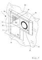
- Figure 1 shows a door station 1 according to the invention, which consists of three Function modules 2a, 2b, 2c is composed L-shaped and so that it includes a horizontal row and a vertical column.
- the door station is attached to a wall element 11 which e.g. Masonry with surface can be or framing one Front door system.
- the front panel 10a of the first functional module shows a perforated field 54, behind which, for example, a loudspeaker and can be a microphone, a second smaller hole field 55, e.g. for light emission from lamps and one Opening 56 e.g. for light entry for a light sensor.
- a bell button 53 is also shown.
- the front panel 10b the second function module shows the optics 56 of a video camera; finally, the front panel 10c of the third function module a closed cover plate, so that this module e.g. the connection and control module can be.
- each module base 8a, 8b, 8c visible.
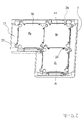
- Mounting screws 24 are adjacent to each other in the module base Screwed in edges of the function modules.
- Each of the function modules has at the corners fastening tabs 25 for immediate attachment of the unit from the functional modules on a wall.
- retaining clips 26 are used, on which the frame 7 is engaged.
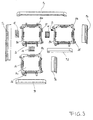
- the door station of Figure 1 is an exploded view omitting the front panels and later shown for explanatory carrier inserts.
- the frame is in his Items 7a to 7f shown disassembled.
- the three Module bases 8a, 8b, 8c with respectively inserted circuit board 9a, 9b, 9c can be seen separately from one another. More matching Details on the modules are still only once designated.
- There are springs or on the outer edges of the module bases Cams 22 and slots or cam receptacles 23 are provided in pairs, who can complement each other and with the previously designated mounting screws 24 for connecting adjacent Serve module units.
- the fastening tabs 25 are visible.
- the retaining clips 26 made of spring plate can be seen in the outer edges the module bases are inserted.
- circuit board 9a On the circuit board 9a is a terminal 12 for sliding on a first Slot 16 shown; between the printed circuit boards 9a, 9b and 9a, 9c there is a connection terminal 15 in the form of a circuit board connector on the slots 16 the edges of the circuit board is pushed open, making openings penetrates in the respective module base.
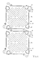
- FIG. 4 shows two module bases 8a, 8b from the underside, a cam / spring 22 and a cam receptacle / slot 23 are provided.
- a screw hole 58 in each case executed by the interlocking of cams and A locking screw can be screwed in which then penetrates the threaded bore 59 of the corresponding cam 22.
- Tabs 25 and pockets 60 formed, which are pushed together of two function modules complementing each other.
- the tabs 25 are designed so that them while making the unit on the wall are bendable to compensate for unevenness without the There is a risk of billing. For this purpose they have one broad base and constant width.
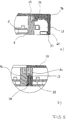
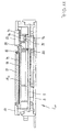
- FIG. 5a shows a partial cross section through a module base 8 an inserted circuit board 9 and an attached front plate 10 shown.
- a holding clamp 26 is located in the module base 8 used, on which a frame part 7b is placed. From Spring steel existing clamp can be when sliding the Compress the frame part inwards so that the U-shape is bent End 27 of the retaining clip receives an inner edge 61 of the frame part.
- a cable duct 13 is formed in the frame part 7b. The Loosening the frame part requires pressing the U-shaped bent end 27 inwards with a special tool.
- FIG. 5b shows two module bases 8a, 8b inserted one into the other, where the interlocking combination of cams 22 and cam receptacle 23 can be seen, the backup takes place by means of the screwed-in fastening screw 24. Since cam 22 and cam receptacle 23 engage in one another essentially without play, a self-supporting unit results from several function modules after screwing in the fastening screws 24.
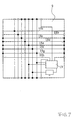
- Figure 6 shows a circuit board 9 as a detail.
- the circuit board is square and has slots on the four edges 16, each comprising four plug contacts 17.
- the individual plug contacts 17 are parallel and intersecting interconnect 18 connected to each other, their crossing points 62 are diagonally offset from each other.
- the above Crossing points represent electrical contacts while others Crossings that can be seen are electrical against each other are isolated.
- Go from the vertically shown conductor tracks 18b further conductor tracks 63 for connecting one on the circuit boards attached electronics unit 19.
- At each of the four slots 16 can be connected to the contacts of the electronics 19th via a corresponding connecting terminal or connecting terminal produce.
- Both all conductor tracks 18 and the plug contacts 17 are designed as printed elements, so that additional connector strips or socket strips on the edges of the Printed circuit board according to the invention are not required.
- the electronics 19 are individual signals of the respective function module to process and convert into control signals for their forwarding within the door station 1 ideally only two conductor tracks 18 are necessary.
- the electronics 19 and the special one Arrangement of the conductor tracks 18 thus allow that all information is exchanged in an internal bus system can be.
- the electronics 19 thus enables Use of BUS technology, so that a reduction in Number of individual terminals is possible.
- the number of connections depends the complexity of the system and the variety of modules; in the In the simplest case, only two connections are necessary, it can however for additional functions (power supply, etc.) also z. B. eight connections or more may be necessary.
- conductor tracks 18 realized, namely conductor tracks 18a and 18b for them Forwarding of a voice two-wire bus through the whole Door station up to the function module that receives the signals of the Recognized voice two-wire bus, conductor tracks 18c and 18d for the Forwarding of a video two-wire bus through the entire door station down to the functional modules, which are designed as video modules are conductor tracks 18e and 18f for the power supply of the individual function modules, a conductor track 18g for data exchange (DATA) of an internal bus system (communication between the individual function modules) and a conductor track 18h for the configuration (TEST) and the detection of Functional problems.
- DATA data exchange
- TEST configuration
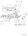
- FIG. 8 shows an individual functional module in an exploded view shown, with the individual module base 8, circuit board 9, front panel 10 recognizable with the details already described is. The same details are given the same reference numbers busy. Openings 65 can be seen in the scope of the module base, for the production of the electrical plug connections serve.
- the openings 65 are each of an elastic Framed seal 21, which is particularly glued, one Closure element in the opening 65 when not in use is clipped in.
- On the front peripheral surface is a sealing one Shaped part 14 shown for receiving a connecting terminal, which can be accommodated in the cable duct of the frame.
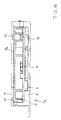
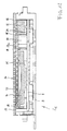
- FIG. 9 shows a functional module 2 9 in section, on which the following details are designated, module base 8, printed circuit board 9, front plate 10 and a carrier insert 28 9 which bears a plurality of name tags 66.
- Sealing elements 67, 68, 69 represent the seal against the ingress of dirt and moisture.
- the openings 65a, 65b are shown, in which case a closing element 20 'made entirely of rubber or elastic plastic is used, while in the second, a multi-part circumferential seal 21 is inserted, through which a connecting terminal 15 is inserted in the form of a circuit board connector.
- This is essentially a one-piece molded part, with internal contact strips not being shown.
- FIG. 10 shows a functional module 2 10 , on which a module base 8, a printed circuit board 9 and a front plate 10 can be recognized as details. Furthermore, a carrier insert 28 10 is provided, which consists of transparent material and penetrates the front plate at two points. On the right side, a light sensor 70 is arranged on the printed circuit board 9, which is supplied with light via the opening 65 in the front plate, the carrier insert 28 10 sealing the interior of the module. The light sensor 70 is electrically connected to an evaluation electronics 71. A lamp, in particular a light-emitting diode 72, is arranged on the printed circuit board 9 on the left-hand side and can emit through an opening 55 in the front plate 10, the material of the carrier insert 28 10 acting as a light guide.
- a lamp in particular a light-emitting diode 72
- FIG. 11 shows functional module 2 11 , on which a module base 8, a printed circuit board 9 and a front plate 10 can be identified as details.
- a carrier insert 28 11 which in turn consists of transparent material, is held behind the front plate 10, which has two openings.
- a bell button 53 is held movably, which is sealed against the carrier insert 28 11 by an inserted or glued-in sealing membrane 73.
- Behind the sealing membrane is a plunger 74 and an elastic element 75, which acts on the actual key switch 76, which is attached to the circuit board.
- the elastic element 75 makes it unnecessary to use a compression spring to reset the bell button.
- a name plate cover 77 is inserted, which is made of transparent material and has a structured rear side 78.
- the actual name plate 79 is located behind this rear side.
- the name plate can be illuminated via a light diode 80 mounted on the printed circuit board 9, a wall part 81 of the carrier insert acting as a light guide, and a reflection surface 82 formed in the carrier insert by a prismatic recess.
- the prism structure serves to deflect the light coming from the light emitting diode 80.
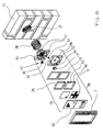
- FIG. 12 shows a functional module 2 12 , on which a module base 8, a printed circuit board 9 and a front plate 10 can be recognized as details.
- Behind the front panel 10 is a carrier insert 28 12 , which has a plurality of walls 83, 84, 85, 86, which form at least three receiving compartments 87, 88, 89.
- a loudspeaker 90 is accommodated in the receiving compartment 87 and is closed in the carrier insert with a cover 91 designed as a perforated plate.
- a microphone 92 is accommodated in the receiving compartment 89.
- the front plate has at least one perforated field 54, the holes in the cover 91 and in the front plate 10 being offset from one another in such a way that mechanical protection of the loudspeaker 90 against willful damage from the outside is ensured.
- FIG. 13 shows a two-core connection cable to be assumed on the building side 93 and a connection cable 94 on the door station side, the dirty with crimp connectors 95 known type and are connected to moisture-proof, the size of the crimp connector is that the accommodation in the cable duct of the Framework is possible.
- FIG. 14-16 show a second embodiment of a Door station 1 'according to the invention, on the one hand in the installed state (Fig. 14), on the other hand in an exploded view (Fig. 15).
- This door station 1 has only two function modules 2a and 2b on.
- This embodiment differs from the first Embodiment essentially on the one hand by the Attaching the circuit board 9 and the cover 10 in the base module 8, on the other hand also by attaching the base modules 8a and 8b with each other.
- the cover 10 and the circuit board 9 are in an additional Carrier insert 28 used, and the resulting unit 29 from cover 10, printed circuit board 9 and carrier insert 28 is snapped into the base module 8.
- the electrical connection the door station 1 with, not shown, coming from the wall 11 electrical lines also take place in that the Function module 2a via a connection terminal 12 to the electrical Lines is connected.
- the electrical Lines first through a - not shown waterproof Cable entry placed in the first base module 8a and with the Terminal 12 connected. From the terminal 12 is done the electrical connection via contact surfaces 30 to corresponding ones Contact pins 31 of the receiving frame 28.
- the electrical The second function module 2b is connected via a connecting terminal 15 to the first function module 2a.
- the mechanical connection between two function modules 2a and 2b takes place via latching elements 32 and a connecting element 33.
- the connecting element 33 is in both base modules 8a, 8b existing guides 34 inserted.
- the locking elements 32 and that Connecting element 33 are designed so that the base modules 8a and 8b can be easily separated from each other if necessary.
- the door station 1 'according to the invention is assembled as follows:
- the first step is the mechanical connection of the two basic modules 8a and 8b.
- these are first by the locking elements 32 plugged together, and then the connector 33 inserted into the guides 34.
- the terminal 12 is on one side of the Base module 8a plugged on.
- a seal 35 is placed on the base module 8a or 8b, and then the units 29a or 29b snapped into the corresponding base modules 8a or 8b.
- the latch mechanism 36 between the unit 29a or 29b and the base module 8a or 8b is designed so that on the one hand a secure connection of the unit 29a or 29b with the Basic module 8a or 8b is guaranteed, on the other hand, the latching but again simply, for example by pushing it in a screwdriver tip. From a circuit board 9, a cover 10 and a receiving frame 28 existing units 29a, 29b are prior to insertion in the base modules 8a, 8b have been assembled, or are in the assembled condition supplied by the manufacturer.
- the frame 7 is then mounted, for what this preferably obliquely on the upper edge of the base module 8a put on, hooked in and then pushed towards wall 11 becomes.
- the frame 7 In the bottom of the frame 7 there is one - here not shown - threaded hole so that the frame 7 final screwed to the base module 8b with a screw can be.
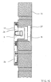
- Fig. 16 shows the door station 1 'in the installed state with a design-related function module 2a with a greater overall height, namely for a video camera 6.
- the one required for the video camera 6 Installation space can now be made available in a simple manner be made with a commercially available drill bit a hole 37 is drilled in the wall 11 and then a normal flush-mounted box 38 inserted in this hole 37 and is plastered if necessary.
- a normal flush-mounted box 38 offers sufficient space for the functional module receiving the video camera 6 2a.
- the second function module 2b has the usual one Ban height as shown in Figure 15.
- the door station 1 thus offers the possibility of to realize a surface-mounted door station that only one "visible" height of maximum 10 to 20 mm.
- the door station 1 is constructed in a modular manner, with the individual functional modules and base modules both mechanically and electrically can be easily connected. Be often Existing flush-mounted door stations replaced by new door stations whereby the old door station often has a larger design than the new door station has. In such a case, it can already existing larger hole in the wall due to the design the cover panel adapted to the door station according to the invention be covered. On this cover panel attached to the wall the door station according to the invention is then screwed on.
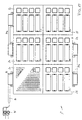
- FIG. 17 shows a door station 1 ′′ according to the invention out of a total six functional modules 2a-2f, it being assumed that Slots only on the top and bottom edges the associated circuit boards are provided, which are vertical parallel conductors are interconnected. For this reason is the functional module 2a via a connector 96 to the Connection cable 94 connected while the modules 2d and 2e over a connector 97a with two connectors and the functional modules 2b, 2c also via a further connector 97b two plugs are connected externally.
- the connector 96 and the connectors 97a, 97b are installed in the cable duct of the frame added.
- the functional module 2a includes light switch, microphone, loudspeaker, light sensor and Function display diode, which comprise further function modules Only bell buttons, name tags and error display diodes.
- the house communication system has two in-house telephones 40, 40 ', two monitors 41, 41 ', a video switching module 42 and a control device 43.
- the control device 43 is used to power the house communication system.
- Door stations 1 and 1 ' are via a video two-wire bus 44 with the monitors 41 and 41 'and one Voice two-wire bus 45 connected to in-house telephones 40 and 40 '.
- connection module 39 or 39 ' The connection module 39 or 39 ' is the functional module, which via the terminal 12 with the electrical Lines is connected.
- the connection module 39 or 39 ' Among other things, it has the task of generating the control signals from inside the door station BUS system in the electronics 19 to prepare that they are in the voice two-wire bus 45 or video two-wire bus 44 can be passed on.
- connection module leads 39 or 39 'a self-configuration of all to the door station 1 or 1 'belonging function modules and stores the position of each function module in a matrix. To do this, it sends Configuration signals to its immediate neighbors by these must be confirmed. As a result, the connection module knows 39 or 39 'its direct neighbors. Then there is the Directed the configuration process to its already found and identified neighbors starting the configuration process control the connection module 39 or 39 'in the same way as before appeals to her neighbors. The connection module 39 or 39 'hears the exchanged information on a conductor track, the DATA line, and thus carries all modules into the configuration matrix on.
- the key module 46 has in the matrix (Row, column) the position (2,1), the motion detector 47 the Position (3.1) etc.
- the connection module 39 now knows all occupied Positions of the matrix as well as the identities (types) of the existing function modules. This configuration is therefore important because every bell button has 3 of all available button modules 46 a specific and unique address can be assigned must in the house telephone 40 belonging to the bell button 3, 40 'is set. Can also be checked through the configuration whether there are functional problems within the door station 1 or 1 ' available. It is also a particular advantage that the person installing a door station without specific expertise can compose as desired without worrying about the internal Need to take care of wiring.
- the video switching module 42 controls this on the one hand with the door stations 1 and 1 'and on the other hand with the Monitors 41 and 41 'connected via the video two-wire bus 44 is the house communication system so that only the door station 1 or 1 ', from which the doorbell rang, via the video two-wire bus 44 connected to the selected monitor 41 or 41 ' is. This ensures that signals are different Do not overlay video modules 48.
- the video switching module 42 receives the information from which door station 1 or 1 ' was rang, via a certain control signal via the Voice two-wire bus 45 from the connection module 39 or 39 '. Has been e.g. rang on the button module 46 of the door station 1, only reports the connection module 39 sends a control signal A to the video switching module 42. Has e.g. rang on the button module 46 'of the door station 1', reports the connection module 39 'a control signal B to the Video switching module 42. The video switching module 42 now switches in the direction of the active door station 1 or 1 '.
- the rang In-house telephone 40 or 40 's witches on and also simultaneously the associated monitor 41 or 41 ', so that the Video image on the correct monitor 41 or 41 'is visible.
- the house communication system described is advantageous the video switching module 42 also via a "picture retrieval button" controllable on the monitor -41 or 41 ', so that the individual video modules 48 or 48 'of the individual door stations 1 or 1' and / or additional external video cameras 49, 49 'activated one after the other can be.
- the "image retrieval button” on monitor 41 or 41 ' becomes a control signal via the voice two-wire bus 45 Video switching module 42 and to the connected door stations 1 and 1 'sent.
- the control signal causes on the one hand in the connection module 39 or 39 'that the associated video camera of the corresponding video module 46 or 46 'is switched on, on the other hand, that with each new key press on the "image retrieval key" the video switching module 42 to the next video module 48 or 48 'or to the next external video camera 49 or 49' toggles. So by calling up the individual video modules 48 or 48 'or the individual external video cameras 49, 49' environmental monitoring can also be carried out.
- Video switching module 42 ideally a special electronic Circuit that enables the coaxial cable 50 of the external Video cameras 49, 49 'with the video two-wire bus 44 of the house communication system to connect (video two-wire converter). Thereby can use commercially available video cameras without additional equipment be connected.
- This video two-wire converter is already door stations 1 and 1 ' integrated.
Landscapes
- Engineering & Computer Science (AREA)
- Signal Processing (AREA)
- Microelectronics & Electronic Packaging (AREA)
- Power-Operated Mechanisms For Wings (AREA)
Abstract
Description
- Figur 1
- ein erstes Ausführungsbeispiel einer erfindungsgemäßen Türstation auf einem Wandelement montiert in Schrägansicht;
- Figur 2
- eine Türstation nach Figur 1 in Rücksansicht;
- Figur 3
- eine Türstation nach den Figuren 1 und 2 in Explosionsdarstellung mit teilmontiertem Funktionsmodul;
- Figur 4
- zwei Funktionsmodule in Unteransicht auf ihre Modulbasis;
- Figur 5
- zwei Einzelheiten einer erfindungsgemäßen Türstation
im Schnitt
- a) Verbindung Funktionsmodul/Rahmen
- b) Verbindung zweier Funktionsmodule
- Figur 6
- eine Leiterplatte eines Funktionsmoduls einer erfindungsgemäßen Türstation in Schrägansicht;
- Figur 7
- eine Leiterplatte nach Figur 6 in ihrem Schaltbild;
- Figur 8
- ein einzelnes Funktionsmodul in Explosionsdarstellung ohne Trägereinsatz;
- Figur 9
- ein Funktionsmodul mit mehreren Namenschildern im Schnitt;
- Figur 10
- ein Funktionsmodul mit einem Lichtsensorelement und mit einer Fehleranzeige im Schnitt;
- Figur 11
- ein Funktionsmodul mit einem Klingeltaster und einem beleuchteten Namensschild im Schnitt;
- Figur 12
- ein Funktionsmodul mit einem Lautsprecher und einem Mikrofon im Schnitt;
- Figur 13
- einen Klemmenanschluß für eine Türstation der genannten Art;
- Figur 14
- eine erfindungsgemäße Türstation einer zweiten Art auf einem Wandelement in Schrägansicht;
- Figur 15
- die Türstation nach Figur 14 in Explosionsdarstellung;
- Figur 16
- die Türstation nach den Figuren 14 und 15 im Querschnitt durch das Wandelement;
- Figur 17
- eine erfindungsgemäße Türstation in einer dritten Ausführung ohne Rahmen;
- Figur 18
- eine Funktionsdarstellung einer Hausanlage mit zwei Türstationen, zwei Videokameras und zwei Hausstationen.
Claims (25)
- Türstation einer aus Türstationen und Wohnungsstationen in einem Gebäude zu bildenden Türanlage mit mehreren Funktionsmodulen, die jeweils zumindest ein Funktionselement - wie Klingeltaster, Lautsprecher, Mikrofon, Videokamera, Bewegungsmelder - sowie mechanische Verbindungselemente und elektrische Verbindungselemente umfassen und die jeweils eine Modulbasis, eine Leiterplatte, eine Frontplatte und ggfs. einen Trägereinsatz umfassen, wobei die Funktionsmodule in Aufsicht rechteckig, insbesondere quadratisch sind und Umfangskanten gleicher Höhe aufweisen und mit den mechanischen Verbindungselementen mit ihren Umfangskanten aneinander grenzend zu einer selbsttragenden Einheit aus in Zeilen und/oder Spalten angeordneten Funktionsmodulen verbindbar sind, und wobei die Funktionsmodule Befestigungsmittel zur unmittelbaren Befestigung der Einheit an einem gebäudeseitigen ortsfesten Wandelement - Mauerwerk mit Aufputz, Umrahmung einer Haustüranlage - aufweist.
- Türstation nach Anspruch 1,
wobei ein die Einheit einfassender nichttragender Rahmen unmittelbar mit der Einheit verbindbar ist, der auf dem gebäudeseitigen ortsfesten Wandelement verbindungslos aufliegt. - Türstation nach einem der Ansprüche 1 oder 2,
wobei die mechanischen Verbindungsmittel an den Umfangskanten der Funktionsmodule angeordnete komplementär ineinandergreifende Laschen und Schlitze sind, wobei die Verbindungen mit die Laschen durchsetzenden Stiften oder Schrauben gesichert sind. - Türstation nach einem der Ansprüche 1 bis 2,
wobei die mechanischen Verbindungsmittel an den Umfangskanten der Funktionsmodule angeodnete komplemetär ineinandergreifende Laschen und Schlitze sind, wobei die Verbindungen durch in Formvorsprünge an den Laschen greifende Rastklinken gesichert sind. - Türstation nach einem der Ansprüche 1 bis 4,
wobei die Einheit mit den Befestigungsmitteln auf der Oberfläche des Wandelements aufliegend montierbar ist. - Türstation nach einem der Ansprüche 1 bis 4,
wobei die Einheit mit den Befestigungsmitteln in eine Öffnung des Wandelements eingesetzt - insbesondere bündig versetzt - montierbar ist. - Türstation nach einem der Ansprüche 1 bis 6,
wobei die Befestigungsmittel höhenverbiegbare Laschen mit Schraubenlöchern sind. - Türstation nach einem der Ansprüche 1 bis 7,
wobei die Leiterplatten zumindest an zwei gegenüberliegenden Kanten Steckplätze haben, deren Steckkontakte mit parallelverlaufenden gedruckten Leitern paarweise miteinander verbunden sind, wobei mit den elektrischen Verbindungsmitteln eine Busstruktur in Zeilen oder in Spalten herstellbar ist. - Türstation nach einem der Ansprüche 1 bis 7,
wobei die Leiterplatten an jeder ihrer Kanten Steckplätze haben, deren Steckkontakte mit kreuzweise verlaufenden zueinander mit ihren Kreuzungspunkten diagonal versetzten gedruckten Leitern quadrupelweise verbunden sind, wobei mit den elektrischen Verbindungsmitteln eine Busstruktur in Zeilen und/oder in Spalten herstellbar ist. - Türstation nach einem der Ansprüche 1 bis 9,
wobei die Steckkontakte als gedruckte Kontakte auf den Leiterplatten ausgebildet sind und die elektrischen Verbindungsmittel weiterhin symmetrische klemmenartige Leiterplattenverbinder umfassen. - Türstation nach einem der Ansprüche 1 bis 10,
wobei die Leiterplatten jeweils unmittelbar in eine Modulbasis eingesetzt sind. - Türstation nach einem der Ansprüche 1 bis 10,
wobei die Leiterplatten jeweils in einem Trägereinsatz eingesetzt sind, der seinerseits unmittelbar mit der Modulbasis verbunden ist. - Türstation nach einem der Ansprüche 1 bis 12,
wobei ein Trägereinsatz aus transparentem Kunststoff besteht und Lichtleiterfunktion zwischen auf der Leiterplatte befestigten Leuchtmitteln und Lichtaustrittsöffnungen in der Frontplatte hat. - Türstation nach einem der Ansprüche 1 bis 13,
wobei ein Trägereinsatz aus transparentem Kunststoff besteht und Lichtleiterfunktion zwischen auf der Leiterplatte befestigten Lichtsensormitteln und einer Lichteintrittsöffnung in der Frontplatte hat. - Türstation nach einem der Ansprüche 1 bis 14,
wobei- ein Funktionsmodul einen Helligkeitssensor und eine Steuerschaltung umfaßt, die helligkeitsabhängig eine Verknüpfung der Klingelbetätigung an der Einheit mit einer Betätigung einer zeitgeschalteten Hausbeleuchtung zuschalten oder abschalten. - Türstation nach einem der Ansprüche 1 bis 15,
wobei ein Funktionsmodul einen Helligkeitssensor und eine Steuerschaltung umfaßt, die helligkeitsabhängig eine Beleuchtung von Namensfeldern an der Einheit zuschalten oder abschalten. - Türstation nach einem der Ansprüche 1 bis 16,
wobei ein Trägereinsatz aus Kunststoff besteht und einen Lautsprecher mit einer Lochplatte zur Abdeckung aufnimmt und wobei die Frontplatte als Lochplatte ausgebildet ist, wobei die Lochraster der beiden Lochplatten zueinander versetzt sind. - Türstation nach einem der Ansprüche 1 bis 17,
wobei ein Trägereinsatz aus transparentem Kunststoff besteht und prismenförmige Reflexionsmittel aufweist, die eine Lichtversorgung einer Beleuchtung für ein in der Frontplatte eingelassenes Namensschild durch ein auf der Leiterplatte befestigtes Leuchtmittel bewirken. - Türstation nach einem der Ansprüche 1 bis 18,
wobei ein Funktionsmodul eine Fehlererkennungsschaltung und eine Leuchtanzeige zur Darstellung ordnungsgemäßer Schaltung und/oder zur Darstellung eines Fehlerstatus aufweist. - Türstation nach Anspruch 19,
wobei zumindest ein Funktionsmodul einen Rücksetzknopf für die Fehlererkennungsschaltung aufweist. - Türstation nach einem der Ansprüche 1 bis 20,
wobei in einem Trägereinsatz durch eine elastische Membran nach außen abgedichtete Tasterelemente angeordnet sind, auf denen Tasterknöpfe aufliegen, die von der Frontplatte beweglich gehalten sind. - Türstation nach einem der Ansprüche 1 bis 21,
wobei für Einheiten mit nur zeilenförmiger Busstruktur oder nur spaltenförmiger Busstruktur Steckverbinderbrücken aus zwei miteinander elektrisch verbundenen Steckverbindern zur Verbindung benachbarter Spaltenbusse oder Zeilenbusse vorgesehen sind. - Türstation nach einem der Ansprüche 1 bis 22,
wobei ein Trägereinsatz eine Mehrzahl von durch Wände gebildeten Aufnahmeabteilen umfaßt, die wahlweise mit verschiedenen Funktionsteilen zur Verwendung in verschiedenen Funktionsmodulen bestückbar sind. - Türstation nach Anspruch 23,
wobei der Trägereinsatz einen Deckel umfaßt, der die Funktionsteile hält. - Türstation nach Anspruch 23,
wobei die Funktionsteile in den Aufnahmeabteilen verklebt oder vergossen sind.
Priority Applications (1)
| Application Number | Priority Date | Filing Date | Title |
|---|---|---|---|
| EP00105540A EP1135013A1 (de) | 2000-03-16 | 2000-03-16 | Türstation |
Applications Claiming Priority (1)
| Application Number | Priority Date | Filing Date | Title |
|---|---|---|---|
| EP00105540A EP1135013A1 (de) | 2000-03-16 | 2000-03-16 | Türstation |
Publications (1)
| Publication Number | Publication Date |
|---|---|
| EP1135013A1 true EP1135013A1 (de) | 2001-09-19 |
Family
ID=8168115
Family Applications (1)
| Application Number | Title | Priority Date | Filing Date |
|---|---|---|---|
| EP00105540A Withdrawn EP1135013A1 (de) | 2000-03-16 | 2000-03-16 | Türstation |
Country Status (1)
| Country | Link |
|---|---|
| EP (1) | EP1135013A1 (de) |
Cited By (8)
| Publication number | Priority date | Publication date | Assignee | Title |
|---|---|---|---|---|
| EP1320244A1 (de) * | 2001-12-11 | 2003-06-18 | GIRA GIERSIEPEN GmbH. & CO. KG | Modulare Hauskommunikationsanlage |
| WO2005029819A1 (de) * | 2003-09-02 | 2005-03-31 | Ritto Gmbh & Co. Kg | Türstation mit namensschilder und klingeltasten |
| AT500037B1 (de) * | 2002-11-18 | 2008-11-15 | Giersiepen Gira Gmbh | Hauskommunikationssystem mit zweidraht-teilnehmeranschluss |
| DE102007022340A1 (de) * | 2007-05-12 | 2009-01-15 | Abb Ag | Sensoreinheit |
| CH701692A1 (de) * | 2009-08-26 | 2011-02-28 | Rene Koch Ag | Innensprechstelle zu Türsprechanlage. |
| US20110227732A1 (en) * | 2010-03-19 | 2011-09-22 | Mr. Christmas Incorporated | Accessory actuator |
| DE102007045870B4 (de) * | 2007-09-25 | 2012-01-05 | Albrecht Jung Gmbh & Co. Kg | Elektrisches/elektronisches Installationsgerät |
| EP3737089A1 (de) | 2019-05-06 | 2020-11-11 | Niko NV | Modulare aussentüreinheit |
Citations (4)
| Publication number | Priority date | Publication date | Assignee | Title |
|---|---|---|---|---|
| DE2711324A1 (de) * | 1977-03-16 | 1978-09-21 | Loh Kg Ritto Werk | Gehaeusebausatz fuer elektrische geraete, insbesondere von sprech- und/ oder klingelanlagen |
| EP0505913A1 (de) * | 1991-03-19 | 1992-09-30 | BITRON VIDEO S.r.l. | System von Audio und/oder Video-Gegensprechanlagen für Gebäude |
| EP0949791A2 (de) * | 1998-04-11 | 1999-10-13 | Ritto - Werk Loh GmbH & Co. KG | Türstation einer Türsprechanlage |
| EP0980200A2 (de) * | 1998-08-12 | 2000-02-16 | Ritto - Werk Loh GmbH & Co. KG | Moduleinheit für eine Türanlage, insbesondere Türsprechanlage |
-
2000
- 2000-03-16 EP EP00105540A patent/EP1135013A1/de not_active Withdrawn
Patent Citations (4)
| Publication number | Priority date | Publication date | Assignee | Title |
|---|---|---|---|---|
| DE2711324A1 (de) * | 1977-03-16 | 1978-09-21 | Loh Kg Ritto Werk | Gehaeusebausatz fuer elektrische geraete, insbesondere von sprech- und/ oder klingelanlagen |
| EP0505913A1 (de) * | 1991-03-19 | 1992-09-30 | BITRON VIDEO S.r.l. | System von Audio und/oder Video-Gegensprechanlagen für Gebäude |
| EP0949791A2 (de) * | 1998-04-11 | 1999-10-13 | Ritto - Werk Loh GmbH & Co. KG | Türstation einer Türsprechanlage |
| EP0980200A2 (de) * | 1998-08-12 | 2000-02-16 | Ritto - Werk Loh GmbH & Co. KG | Moduleinheit für eine Türanlage, insbesondere Türsprechanlage |
Cited By (11)
| Publication number | Priority date | Publication date | Assignee | Title |
|---|---|---|---|---|
| EP1320244A1 (de) * | 2001-12-11 | 2003-06-18 | GIRA GIERSIEPEN GmbH. & CO. KG | Modulare Hauskommunikationsanlage |
| AT500037B1 (de) * | 2002-11-18 | 2008-11-15 | Giersiepen Gira Gmbh | Hauskommunikationssystem mit zweidraht-teilnehmeranschluss |
| NL1024800C2 (nl) * | 2002-11-18 | 2009-10-06 | Giersiepen Gira Gmbh | Huiscommunicatiesysteem met tweedraads-abonneeaansluiting. |
| WO2005029819A1 (de) * | 2003-09-02 | 2005-03-31 | Ritto Gmbh & Co. Kg | Türstation mit namensschilder und klingeltasten |
| DE102007022340A1 (de) * | 2007-05-12 | 2009-01-15 | Abb Ag | Sensoreinheit |
| EP1993180A3 (de) * | 2007-05-12 | 2016-03-09 | Abb Ag | Sensoreinheit zur Montage in einer Installationsdose |
| DE102007045870B4 (de) * | 2007-09-25 | 2012-01-05 | Albrecht Jung Gmbh & Co. Kg | Elektrisches/elektronisches Installationsgerät |
| CH701692A1 (de) * | 2009-08-26 | 2011-02-28 | Rene Koch Ag | Innensprechstelle zu Türsprechanlage. |
| US20110227732A1 (en) * | 2010-03-19 | 2011-09-22 | Mr. Christmas Incorporated | Accessory actuator |
| EP3737089A1 (de) | 2019-05-06 | 2020-11-11 | Niko NV | Modulare aussentüreinheit |
| BE1027256B1 (nl) * | 2019-05-06 | 2020-12-07 | Niko Nv | Modulaire buitenpost |
Similar Documents
| Publication | Publication Date | Title |
|---|---|---|
| EP0452658B1 (de) | Anschlusseinrichtung für die Hausleittechnik | |
| EP0677986B1 (de) | Baugruppe eines Automatisierungsgeräts | |
| DE8223064U1 (de) | Vorrichtung für elektrische Geräte zur äußeren Eingabe und/oder Anzeige von Informationen | |
| DE19943570B4 (de) | Türstation | |
| DE69116678T2 (de) | Beleuchtungsregelung für ein energieverwaltungssystem | |
| EP3186862B1 (de) | Automatisierungsmodul für die gebäudeautomation | |
| DE202017103605U1 (de) | Beleuchtungseinrichtung | |
| DE69222796T3 (de) | System für den Zusammenbau einer externen Rufeinheit für eine Audio und/oder Video-Gebäudegegensprechanlage | |
| EP1135013A1 (de) | Türstation | |
| EP0701364B1 (de) | Videokamera | |
| DE29809106U1 (de) | Installationseinrichtung | |
| DE202019105275U1 (de) | Funktionsmodul | |
| DE19622877C2 (de) | Systemleuchte | |
| DE102007058170B4 (de) | Elektrisches/elektronisches Installationsgerät | |
| DE10001053C1 (de) | Klingeltastermodul | |
| DE102007045869B3 (de) | Elektrisches/elektronisches Installationsgerät | |
| EP3430875B1 (de) | Elektronische reihenklemme für einen datenbus | |
| DE69716865T2 (de) | Zusammensetzungssystem für Aussenstationen in Gegensprechanlage- und Videogegensprachanlagevorrichtungen | |
| DE20104726U1 (de) | Multifunktionsleuchte | |
| DE102007045866B3 (de) | Montageanordnung und deren Verwendung in einem Installationsgerät | |
| DE19830271A1 (de) | Beleuchtungseinrichtung in Modulbauweise | |
| EP0992045A1 (de) | Verfahren zum ausführen einer elektroinstallation und bausatz für elektroinstallation | |
| EP1251627A2 (de) | Elektromotorischer Antrieb | |
| DE19745385A1 (de) | Verfahren zum Ausführen einer Elektroinstallation und Bausatz für Elektroinstallation | |
| EP1033905B1 (de) | Modulares Präsenzmeldersystem |
Legal Events
| Date | Code | Title | Description |
|---|---|---|---|
| PUAI | Public reference made under article 153(3) epc to a published international application that has entered the european phase |
Free format text: ORIGINAL CODE: 0009012 |
|
| 17P | Request for examination filed |
Effective date: 20000929 |
|
| AK | Designated contracting states |
Kind code of ref document: A1 Designated state(s): AT BE CH CY DE LI Kind code of ref document: A1 Designated state(s): AT BE CH CY DE DK ES FI FR GB GR IE IT LI LU MC NL PT SE |
|
| AX | Request for extension of the european patent |
Free format text: AL;LT;LV;MK;RO;SI |
|
| RAP1 | Party data changed (applicant data changed or rights of an application transferred) |
Owner name: HORST SIEDLE GMBH & CO. KG. |
|
| AKX | Designation fees paid |
Free format text: AT BE CH CY DE LI |
|
| RBV | Designated contracting states (corrected) |
Designated state(s): DE ES FR IT NL |
|
| 17Q | First examination report despatched |
Effective date: 20040512 |
|
| STAA | Information on the status of an ep patent application or granted ep patent |
Free format text: STATUS: THE APPLICATION HAS BEEN WITHDRAWN |
|
| 18W | Application withdrawn |
Effective date: 20040729 |