EP1134820A1 - Method of joining the electrode lugs with a terminal of an electrochemical generator and generator - Google Patents
Method of joining the electrode lugs with a terminal of an electrochemical generator and generator Download PDFInfo
- Publication number
- EP1134820A1 EP1134820A1 EP01400537A EP01400537A EP1134820A1 EP 1134820 A1 EP1134820 A1 EP 1134820A1 EP 01400537 A EP01400537 A EP 01400537A EP 01400537 A EP01400537 A EP 01400537A EP 1134820 A1 EP1134820 A1 EP 1134820A1
- Authority
- EP
- European Patent Office
- Prior art keywords
- terminal
- holding element
- ring
- welding
- strips
- Prior art date
- Legal status (The legal status is an assumption and is not a legal conclusion. Google has not performed a legal analysis and makes no representation as to the accuracy of the status listed.)
- Granted
Links
Images


Classifications
-
- B—PERFORMING OPERATIONS; TRANSPORTING
- B23—MACHINE TOOLS; METAL-WORKING NOT OTHERWISE PROVIDED FOR
- B23K—SOLDERING OR UNSOLDERING; WELDING; CLADDING OR PLATING BY SOLDERING OR WELDING; CUTTING BY APPLYING HEAT LOCALLY, e.g. FLAME CUTTING; WORKING BY LASER BEAM
- B23K26/00—Working by laser beam, e.g. welding, cutting or boring
- B23K26/009—Working by laser beam, e.g. welding, cutting or boring using a non-absorbing, e.g. transparent, reflective or refractive, layer on the workpiece
-
- B—PERFORMING OPERATIONS; TRANSPORTING
- B23—MACHINE TOOLS; METAL-WORKING NOT OTHERWISE PROVIDED FOR
- B23K—SOLDERING OR UNSOLDERING; WELDING; CLADDING OR PLATING BY SOLDERING OR WELDING; CUTTING BY APPLYING HEAT LOCALLY, e.g. FLAME CUTTING; WORKING BY LASER BEAM
- B23K26/00—Working by laser beam, e.g. welding, cutting or boring
- B23K26/08—Devices involving relative movement between laser beam and workpiece
- B23K26/10—Devices involving relative movement between laser beam and workpiece using a fixed support, i.e. involving moving the laser beam
-
- H—ELECTRICITY
- H01—ELECTRIC ELEMENTS
- H01M—PROCESSES OR MEANS, e.g. BATTERIES, FOR THE DIRECT CONVERSION OF CHEMICAL ENERGY INTO ELECTRICAL ENERGY
- H01M50/00—Constructional details or processes of manufacture of the non-active parts of electrochemical cells other than fuel cells, e.g. hybrid cells
- H01M50/50—Current conducting connections for cells or batteries
- H01M50/528—Fixed electrical connections, i.e. not intended for disconnection
-
- H—ELECTRICITY
- H01—ELECTRIC ELEMENTS
- H01M—PROCESSES OR MEANS, e.g. BATTERIES, FOR THE DIRECT CONVERSION OF CHEMICAL ENERGY INTO ELECTRICAL ENERGY
- H01M50/00—Constructional details or processes of manufacture of the non-active parts of electrochemical cells other than fuel cells, e.g. hybrid cells
- H01M50/50—Current conducting connections for cells or batteries
- H01M50/531—Electrode connections inside a battery casing
- H01M50/533—Electrode connections inside a battery casing characterised by the shape of the leads or tabs
-
- H—ELECTRICITY
- H01—ELECTRIC ELEMENTS
- H01M—PROCESSES OR MEANS, e.g. BATTERIES, FOR THE DIRECT CONVERSION OF CHEMICAL ENERGY INTO ELECTRICAL ENERGY
- H01M50/00—Constructional details or processes of manufacture of the non-active parts of electrochemical cells other than fuel cells, e.g. hybrid cells
- H01M50/50—Current conducting connections for cells or batteries
- H01M50/531—Electrode connections inside a battery casing
- H01M50/534—Electrode connections inside a battery casing characterised by the material of the leads or tabs
-
- H—ELECTRICITY
- H01—ELECTRIC ELEMENTS
- H01M—PROCESSES OR MEANS, e.g. BATTERIES, FOR THE DIRECT CONVERSION OF CHEMICAL ENERGY INTO ELECTRICAL ENERGY
- H01M50/00—Constructional details or processes of manufacture of the non-active parts of electrochemical cells other than fuel cells, e.g. hybrid cells
- H01M50/50—Current conducting connections for cells or batteries
- H01M50/531—Electrode connections inside a battery casing
- H01M50/538—Connection of several leads or tabs of wound or folded electrode stacks
-
- Y—GENERAL TAGGING OF NEW TECHNOLOGICAL DEVELOPMENTS; GENERAL TAGGING OF CROSS-SECTIONAL TECHNOLOGIES SPANNING OVER SEVERAL SECTIONS OF THE IPC; TECHNICAL SUBJECTS COVERED BY FORMER USPC CROSS-REFERENCE ART COLLECTIONS [XRACs] AND DIGESTS
- Y02—TECHNOLOGIES OR APPLICATIONS FOR MITIGATION OR ADAPTATION AGAINST CLIMATE CHANGE
- Y02E—REDUCTION OF GREENHOUSE GAS [GHG] EMISSIONS, RELATED TO ENERGY GENERATION, TRANSMISSION OR DISTRIBUTION
- Y02E60/00—Enabling technologies; Technologies with a potential or indirect contribution to GHG emissions mitigation
- Y02E60/10—Energy storage using batteries
-
- Y—GENERAL TAGGING OF NEW TECHNOLOGICAL DEVELOPMENTS; GENERAL TAGGING OF CROSS-SECTIONAL TECHNOLOGIES SPANNING OVER SEVERAL SECTIONS OF THE IPC; TECHNICAL SUBJECTS COVERED BY FORMER USPC CROSS-REFERENCE ART COLLECTIONS [XRACs] AND DIGESTS
- Y02—TECHNOLOGIES OR APPLICATIONS FOR MITIGATION OR ADAPTATION AGAINST CLIMATE CHANGE
- Y02P—CLIMATE CHANGE MITIGATION TECHNOLOGIES IN THE PRODUCTION OR PROCESSING OF GOODS
- Y02P70/00—Climate change mitigation technologies in the production process for final industrial or consumer products
- Y02P70/50—Manufacturing or production processes characterised by the final manufactured product
-
- Y—GENERAL TAGGING OF NEW TECHNOLOGICAL DEVELOPMENTS; GENERAL TAGGING OF CROSS-SECTIONAL TECHNOLOGIES SPANNING OVER SEVERAL SECTIONS OF THE IPC; TECHNICAL SUBJECTS COVERED BY FORMER USPC CROSS-REFERENCE ART COLLECTIONS [XRACs] AND DIGESTS
- Y10—TECHNICAL SUBJECTS COVERED BY FORMER USPC
- Y10T—TECHNICAL SUBJECTS COVERED BY FORMER US CLASSIFICATION
- Y10T29/00—Metal working
- Y10T29/49—Method of mechanical manufacture
- Y10T29/49002—Electrical device making
- Y10T29/49108—Electric battery cell making
Definitions
- the present invention relates to a method of connecting the lamellae coming from an electrode to a terminal of an electrochemical generator, in particular, a rechargeable lithium electrochemical generator with electrodes spiral cylindrical.
- the invention also relates to an electrochemical generator likely to be obtained by this process.
- An electrochemical generator with spiral electrodes includes electrodes in the form of ribbons wound around a central mandrel or bobbin to form a cylinder.
- Each electrode includes a current collector metallic which supports on at least one of its faces the active material of the electrode. It is electrically connected to a current output terminal which ensures electrical continuity between the electrode and the application to which the generator is associated.
- the terminal crosses the generator container: the part located outside of the container receives the external connections, the part located inside is connected to the electrodes.
- This terminal can be integral or attached to the container. It exists Several ways to electrically connect an electrode to a current output. One of these ways is the use of one or more conductive or thin strips metal strips: one end of each of the strips is welded to the edge of the manifold and the other end is soldered to the internal part of the terminal located at inside the container.
- FR-A-2752089 describes a method for connecting the slats coming from of an electrode of such an electrochemical generator to a terminal attached to its container.
- the inner part of the terminal container includes a shoulder cylindrical.
- the method consists in gathering the lamellae around the periphery of the shoulder by a cylindrical part animated by a concentric movement towards the periphery. Then, the slats are fixed on the periphery using in particular a ring or by using electrical or ultrasonic welding.
- This process has the disadvantage of inducing a long manufacturing time.
- the electric welding or ultrasonic welding is not of good quality satisfactory when it comes to welding, for example, aluminum slats on aluminum bollards.
- Electric welding is difficult to implement in especially when several lamellae overlap as this results in a cumulation of contact resistances between the various lamellae and the terminal which is such that the electric welding becomes impossible or at least provides quality welding poor no longer reliably making the mechanical connection and slats at the terminal.
- the disadvantage of ultrasonic welding is do not allow to successively weld the slats to the terminal because vibrations generated during the welding of a given strip deteriorate or destroy the welding of the previous strip.
- the object of the present invention is to eliminate the drawbacks of the art prior.
- the lamellae each preferably have a thickness of between 50 ⁇ m and 80 ⁇ m.
- the holding element preferably has a thickness of between 0.5mm and 1mm.
- the terminal, the slats and the holding element are made of aluminum.
- the terminal and the slats are produced each in a material chosen from copper, nickel-plated copper and nickel, and the holding element is made of nickel or nickel-plated copper.
- the method preferably comprises the folding of the lamellae on the flat part from a peripheral edge of the flat part, before pinching and welding. It is therefore advantageous if the terminal has a cylindrical part on one face of which the flat part is arranged and that the holding element is a washer.
- the invention proposes an electrochemical generator, in which lamellae from an electrode are arranged between a terminal and a holding element, and comprising at least one weld passing through the element holding and the slats and entering the terminal.
- the slats each have preferably a thickness between 50 ⁇ m and 80 ⁇ m.
- the holding element has preferably a thickness between 0.5mm and 1mm.
- the terminal, the slats and the holding element are made of aluminum.
- the terminal and the slats are produced each in a material chosen from copper, nickel-plated copper and nickel and that the holding element is made of nickel or nickel-plated copper.
- the slats are preferably folded down on the flat part to from a peripheral edge of the flat part. It is therefore advantageous if the terminal has a cylindrical part on one face of which the flat part is arranged and that the holding element is a washer.
- the invention proposes to connect the lamellae coming from an electrode to an electrochemical generator terminal by pinching these strips between an element and the terminal for pressing and holding the slats against the terminal during the welding of the lamellae on the terminal using a welding with laser by transparency through the holding element.
- Laser welding by transparency consists in attacking a point on the surface with the laser beam outside of the holding element to gradually melt the thickness of material of the holding element at this point.
- the beam continues its attack on the or the underlying lamellae to melt the material thickness of these slats and then finally the underlying material of the terminal at least at one level superficial.
- the beam laser is moved gradually, preferably continuously, along a welding line on the outer surface of the holding element for welding the set of lamellae on the terminal along this weld line, the speed of displacement being chosen to obtain the effective welding of the holding element, lamellae and terminal along the weld line.
- This generator typically comprises an electrochemical beam including a positive electrode and a negative electrode as well as two separators.
- the two electrodes are wound or spiraled together with the separators interposed between them to form a cylinder.
- Each electrode is connected to an output corresponding current by means of metal strips.
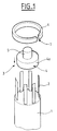
- FIG. 1 represents a spiral electrode 1 connected to a plurality of metal strips 2 before their connection to a current output terminal 3.
- the strips 2 are used to electrically connect the electrode 1 to the terminal 3.
- the slats 2 are generally all the same thickness. The number of slats 2 represented is not significant and depends in fact on the power of the electrochemical generator.
- Terminal 3 includes a connection pad 5 which will usually disposed on the outside of the generator housing, not shown, and a connection part 4 which will usually be located inside the housing of the generator.
- Connection pad 5 receives the connection from the external application to which the generator is associated by means, for example, of a thread not represented.
- the connection part 4 has the shape of a cylinder of revolution on one face of which the connection pad 5 is arranged.
- the connection pad 5 does not not protrude radially outside the circumference 4a of the connecting part 4.
- the connection of the slats 2 to the terminal 3 is carried out using a holding in the form of a split cylindrical ring 6,
- connection part 4 is arranged between the lamellae 2 so that the lamellae 2 extend around the circumference 4a of the connection part 4, as illustrated in FIG. 2.
- the connection pad 5 is obviously located on the opposite side to the electrode 1. Terminal 3 could for example be held by a tool tightening the connection pad 5.
- the ring 6 is placed around the circumference 4a of the connection part 4 and of the strips 2.
- the strips 2 are therefore arranged between the circumference 4a of the connection part 4 and the ring 6.
- the ring 6 when it is not stressed, has a diameter interior greater than the diameter of the connection part 4 and sufficient for ability to surround conference 4a with connection part 4 with lamellae 2 arranged around it.
- the ring 6 is then tightened on the circumference 4a of the connection part 4 using for example a clamp concentric, not shown. Consequently, the slats 2 are pinched between the circumference 4a of the connecting part 4 and the ring 6 as illustrated in Figure 3.
- a person skilled in the art will choose the material and the dimensions of the ring 6 of so as to have sufficient elasticity to allow this tightening. Likewise, it choose the width of the slot 7 of the ring 6 to allow the reduction of sufficient diameter of the ring 6 when tightening it. Tightening is done only over part 8 of the width of the outer circumference of the ring 6 which is shown hatched in FIG. 3.
- the setting place of the ring 6 will then be done by increasing its diameter with a spreader tool adapted to allow the ring 6 to pass around the circumference 4a of the connection part 4 and lamellae 2. Then, the stress on the ring 6 ceases so that it encloses the circumference of the connecting part 4 so that pinch the slats together.
- the skilled person will choose the material and the dimensions at rest of the ring 6 to provide sufficient elasticity for allow the increase in diameter and to obtain a pinching force of the strips between the connecting part 4 and the ring 6 sufficient.
- the shape of the ring 6 can be arranged to facilitate its grip by the spreader tool for example at like a classic elastic tree ring.
- the plates 2 are welded to the circumference 4a of the connection part 4.
- the welding is carried out by laser by transparency at across the ring 6 along a weld line 9 going around the outer circumference of the ring 6 and which is shown in dotted lines on the figure 3.
- the tightening of the ring 6 on the connection part 4 is used to press and hold the strips 2 against the connection part 4 to allow reliable welding of the lamellae 2 on the connection part 4.
- the laser welding is done by transparency, that is to say that the laser beam attacks at a point on the welding line 9 on the outer circumference of ring 6 and gradually melts first the material thickness of the ring 6, then the material of the lamellae 2 and finally at minus the material on the surface of the connection part 4, for welding together these different elements.
- the laser beam progressively travels the line of welding 9 to perform the welding all along it.
- a person skilled in the art will choose the materials of the slats 2, of the terminal 3 and of the ring 6, as well as an adequate material thickness of the lamellae 2 and of the ring 6 in the area of the welding line 9 to allow laser welding by transparency. He will also choose the laser power to use which can be of the continuous or pulsed type, as well as its speed of movement.
- the width of the ring 6 will preferably be at least equal to the thickness of the part connection 4 so that the ring 6 can enclose the entire width of its circumference 4a.
- Welding could be limited to only portions of the welding line 9 which correspond to the slats 2 and therefore by not welding if necessary the ring 6 on the connection part 4 where there is no lamella 2 interposed. But in reality it is simpler to carry out the welding all along the weld line 9 around the outer circumference of the ring 6, which has in addition, the advantage of securing ring 6 more securely and reliably the connection part 4.
- the lamellae 2 may possibly overlap on the circumference of the connection part 4 when the tightening of the ring 6 ensures the plating of all the slats against the connection part 4 to allow laser welding by transparency. In this case, when welding laser transparency, the laser beam will attack as and when slats 2 superimposed until reaching terminal 3.
- a metallic material which is sufficiently malleable for the ring 6 to ability to effectively lay all the slats 2 on terminal 3 in the case where the number of overlapping slats 2 varies according to the position on the circumference 4a of the connecting part 4, that is to say that the thickness resulting from the lamellae 2 around the connection part 4 is not constant.
- the slats 2 preferably stop flush with the edge of the circumference of the connection part 4 on the side of the connection pad 5 as illustrated in figures 2 and 3, cutting them if necessary at any time before, during or after the implementation of connection operations previously described.
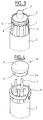
- Figures 4 and 5 illustrate a second embodiment of the invention which is a variant of the first embodiment.
- Terminal 10 includes a connection part 4 which will usually located inside the generator housing.
- the part of connection 4 is identical to that of terminal 3 in the first mode of realization and has the same function of connecting the slats 2 coming from the electrode 1.
- the terminal 10 comprises a connection cover 11 which will usually disposed on the outside of the generator housing, not shown, and which allows the electrical connection of the generator with the external application such as the connection pad 5 in the first embodiment.
- the cover 11 has a circular section and is integral with the connection part 4 with which it is coaxial.
- the cover 11 has a diameter greater than that of the part of connection 4 and therefore protrudes radially from the circumference of the part of connection 4.
- the lamellae 2 are gathered between the ring 6 and the circumference 4a of the part of connection 4 with the ring 6 enclosing the circumference 4a of the part of connection 4 to allow laser welding by transparency along a weld line around the outer circumference of the ring 6.
- modify the operating mode described for the first mode of realization as follows. First, place the ring 6 around the slats 2 as illustrated in Figure 4.
- the slats 2 preferably stop flush with the edge of the circumference 4a of the connection part 4 on the side of the cover 10 as illustrated in Figure 5, cutting them if necessary preferably before setting implementation of the connection operations previously described. Slats 2 can also stop flush along the edge of the outer circumference of the ring 6 on the side of the cover 10 by cutting them after fitting and tightening of the ring 6 around the connection part 4. As a variant, the strips 2 can also be cut flush along the edge of the circumference of the cover 10 on the side of ring 6 by cutting them after fitting and tightening the ring 6 around the connection part 4.
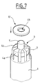
- Figures 6, 7 and 8 show a third embodiment of the invention which is a variant of the first embodiment.
- the part of the slats 2 which projects by the connection part 4 on the face 4b of the connection part 4 on the side of the connection pad 5, as illustrated in FIG. 7.
- the strips 2 extend from preferably on the face 4b without going up along the connection pad 5, at need by cutting them at any time before, during or after setting connection operations being described.
- the drawdown of slats 2 on the face 4b can be done for example by means of a tool comprising three to six branches moving concentrically from the outside of terminal 3 towards the axis thereof.
- the washer 12 is placed on the face 4b of the connection part 4 so that the slats 2 are arranged between the face 4b and the washer 12, as illustrated in FIGS. 7 and 8.
- the washer 12 has an opening 13 corresponding to the cross section of the connection pad 5.
- the connection pad has a circular cross section and coaxial with the connection part 4. So as to correspond to terminal 3, the washer 12 is advantageously circular outer diameter corresponding to that of the connection part 4 and the opening 13 is also circular and coaxial with the outer circumference of the connection pad 5.
- the washer 12 is then pressed against the face 4b of the part of connection 4 using for example a hollow cylindrical tool 14 supported on the washer 12 around the connection pad 5.
- the support zone of the tool 14 on the face 4b is shown hatched and referenced 15.
- the face opposite the face 4b of the connection part 4 may for example press against the mandrel of electrode 1 or be supported by suitable tools such as a threaded rod screwed into a connection thread, not shown, arranged in the connection pad 5. Consequently, the strips 2 are pinched between the face 4b of the connection part 4 and the washer 12.
- the plates 2 are welded to the face 4b of the connection part 4 similarly to the first embodiment, but on the face of the washer 12.
- the welding is carried out by laser by transparency through the washer 12 along a welding line 16, around the stud connection 5, which is shown in dotted lines in FIG. 8.
- the welding line 16 is located on the face of the washer 12 outside the zone 15 on which the tool 14 rests. Laser welding is done by transparency, i.e.
- the laser beam travels gradually the welding line 16 for carrying out the welding all along the latter.
- Welding could be limited to only portions of the welding line welding 16 which corresponds to the lamellae 2 and therefore not welding the case if necessary the washer 12 on the connection part 4 at the places where there is no lamella 2 interposed. But in reality it is easier to carry out the welding while along the weld line 16 around the connection pad 5, which further for advantage of securely and securely securing the washer 12 with the part of connection 4.
- a person skilled in the art will choose the materials of the slats 2, of the terminal 3 and of the washer 12, as well as an adequate material thickness of the lamellae 2 and of the washer 12 in the area of the welding line 16 to allow welding to laser by transparency. He will also choose the laser power to use, which can be of the continuous or pulsed type.
- the diameter of the washer 12 will be preferably at least equal to the diameter of the connection part 4 so that the washer 12 can enclose the entire face 4b of the connection part 4.
- the lamellae 2 can also be overlap on the face 4b of the connection part 4 as soon as the effort of tightening applied to the washer 12 ensures the plating of all of the strips 2 against the face 4b of the connection part 4 to allow the laser welding by transparency.
- the slats 2 will be welded between they at the level of the overlapping parts.
- metal material sufficiently malleable for the washer 12 if the number of overlapping lamellae 2 varies according to the position on the face 4b of the connection part 4, i.e. the resulting thickness of the lamellae 2 around the connecting part 4 is not constant.
- the slats 2, the terminal 3 or 10 and the ring 6 or the washer 12 are of preferably made from metallic materials compatible from a point of view electrochemical.
- the material of the ring 6 or of the washer 12 is chosen. compatible with laser welding by transparency through it, counts given its thickness, i.e. a material which reflects little or no beam laser welding. So, if it is the terminal and the lamellae of an electrode positive, all three will advantageously be made of aluminum. If this is the terminal and strips of a negative electrode, the strips and the terminal will be preferably in nickel, copper or nickel-plated copper while ring 6 or washer 12 will preferably be made of nickel or nickel-plated copper which ensure better transparency to laser welding - i.e. lower beam reflection laser - than copper.
- the lamellae 2 preferably have a thickness of between 50 ⁇ m (50 micrometers) and 80 ⁇ m (80 micrometers), which makes it possible to obtain particularly good laser welding by transparency.
- the thickness of the ring 6 or the washer 12 in the region of the welding line 9 or 16 is preferably between 0.5mm and 1mm.
- the slats 2 generally have a width of between 2mm and 10mm.
- the diameter of the part of connection 4 is for example between 25mm and 50mm and its thickness is advantageously at least equal to 4mm.
- the diameter of the connection part 4 is for example between 30mm and 50mm and the diameter of the connection pad 5 is for example between 8mm and 15mm.
- the average pressing pressure of the ring 6 or of the washer 12 against the connection part 4 - the strips 2 being pinched together - during the laser welding by transparency is preferably between 30N / cm 2 and 60N / cm 2 .
- This indication is given assuming theoretically a uniform distribution of the forces of the ring 6 or of the washer 12 on the connection part 4.
- the clamping force applied to the washer 12 with the tool 14 could advantageously be between 150N and 200N for a washer 12 having an outside diameter of 30mm corresponding to that of the connection part 4 and the opening 13 of which has a diameter of 15mm.
- Welding can for example be carried out with a continuous YAG laser with a power of about 2000W for a thickness of ring 6 or washer 12 of 0.5mm and a superposition of five lamellas 2 on each other at the level of the connection part 4, by adopting a beam displacement speed laser of the order of 10m / min.
- Laser welding by transparency provides a connection solid and reliable mechanical slats 2 at terminal 3 - further reinforced by the welding of the ring 6 or the washer 12 on the slat / terminal assembly - thus than a high quality electrical connection.
- the third embodiment still has the advantage of simplifying the positioning and plating of the strips 2 on the connection part 4 of the terminal 3 using a tool simpler and allowing faster, and therefore more economical, of these operations.
- the plating part of the lamellae 2 against the part of connection 4 comes down to a simple, very inexpensive washer.
- the present invention is not limited to the examples and to the embodiments described and represented, but it is susceptible of numerous variants accessible to those skilled in the art.
- the invention can be applied to an electrochemical generator of a type other than rechargeable.
- the holding element no longer performs the lamella holding function against the terminal after welding with the lamellae on the terminal; this is where resulting solder which keeps the strips on the terminal. Nevertheless we continued to designate it by these same terms - that is to say by holding element - after the welding, both in the description and in the claims.
Abstract
Description
La présente invention concerne un procédé de raccordement des lamelles provenant d'une électrode à une borne d'un générateur électrochimique, en particulier, d'un générateur électrochimique rechargeable au lithium à électrodes cylindriques spiralées. L'invention concerne aussi un générateur électrochimique susceptible d'être obtenu par ce procédé.The present invention relates to a method of connecting the lamellae coming from an electrode to a terminal of an electrochemical generator, in particular, a rechargeable lithium electrochemical generator with electrodes spiral cylindrical. The invention also relates to an electrochemical generator likely to be obtained by this process.
Un générateur électrochimique à électrodes spiralées comprend des électrodes sous forme de rubans enroulés autour d'un mandrin central ou bobinot pour former un cylindre. Chaque électrode comprend un collecteur de courant métallique qui supporte sur au moins une de ses faces la matière active de l'électrode. Elle est connectée électriquement à une borne de sortie de courant qui assure la continuité électrique entre l'électrode et l'application à laquelle le générateur est associé.An electrochemical generator with spiral electrodes includes electrodes in the form of ribbons wound around a central mandrel or bobbin to form a cylinder. Each electrode includes a current collector metallic which supports on at least one of its faces the active material of the electrode. It is electrically connected to a current output terminal which ensures electrical continuity between the electrode and the application to which the generator is associated.
La borne traverse le conteneur du générateur : la partie située à l'extérieur du conteneur reçoit les connexions extérieures, la partie située à l'intérieur est reliée aux électrodes. Cette borne peut être solidaire ou rapportée au conteneur. Il existe plusieurs façons de raccorder électriquement une électrode à une sortie de courant. L'une de ces façons est l'utilisation d'une ou plusieurs lamelles conductrices ou minces bandes métalliques : une extrémité de chacune des lamelles est soudée sur le bord du collecteur et l'autre extrémité est soudée à la partie interne de la borne située à l'intérieur du conteneur.The terminal crosses the generator container: the part located outside of the container receives the external connections, the part located inside is connected to the electrodes. This terminal can be integral or attached to the container. It exists Several ways to electrically connect an electrode to a current output. One of these ways is the use of one or more conductive or thin strips metal strips: one end of each of the strips is welded to the edge of the manifold and the other end is soldered to the internal part of the terminal located at inside the container.
FR-A-2752089 décrit un procédé pour raccorder les lamelles provenant d'une électrode d'un tel générateur électrochimique à une borne rapportée sur son conteneur. La partie intérieure au conteneur de la borne comprend un épaulement cylindrique. Le procédé consiste à rassembler les lamelles autour de la périphérie de l'épaulement par une pièce cylindrique animée d'un mouvement concentrique vers la périphérie. Puis, les lamelles sont fixées sur la périphérie en utilisant notamment une bague ou en recourant à une soudure électrique ou par ultrasons. FR-A-2752089 describes a method for connecting the slats coming from of an electrode of such an electrochemical generator to a terminal attached to its container. The inner part of the terminal container includes a shoulder cylindrical. The method consists in gathering the lamellae around the periphery of the shoulder by a cylindrical part animated by a concentric movement towards the periphery. Then, the slats are fixed on the periphery using in particular a ring or by using electrical or ultrasonic welding.
Ce procédé a pour inconvénient d'induire un temps de fabrication long. En outre, la soudure électrique ou la soudure aux ultrasons n'est pas de qualité satisfaisante lorsqu'il s'agit de souder par exemple des lamelles en aluminium sur des bornes en aluminium. Le soudage électrique est délicat à mettre en oeuvre en particulier lorsque plusieurs lamelles se chevauchent car il en résulte un cumul des résistances de contact entre les différentes lamelles et la borne qui est tel que le soudage électrique devient impossible ou du moins procure une soudure de qualité médiocre ne réalisant plus de manière fiable le raccordement mécanique et électrique des lamelles à la borne. Le soudage par ultrasons a pour inconvénient de ne pas permettre de souder successivement les lamelles à la borne car les vibrations engendrées lors du soudage d'une lamelle donnée détériorent ou détruisent la soudure de la lamelle précédente.This process has the disadvantage of inducing a long manufacturing time. In besides, the electric welding or ultrasonic welding is not of good quality satisfactory when it comes to welding, for example, aluminum slats on aluminum bollards. Electric welding is difficult to implement in especially when several lamellae overlap as this results in a cumulation of contact resistances between the various lamellae and the terminal which is such that the electric welding becomes impossible or at least provides quality welding poor no longer reliably making the mechanical connection and slats at the terminal. The disadvantage of ultrasonic welding is do not allow to successively weld the slats to the terminal because vibrations generated during the welding of a given strip deteriorate or destroy the welding of the previous strip.
La présente invention a pour but d'éliminer les inconvénients de l'art antérieur.The object of the present invention is to eliminate the drawbacks of the art prior.
A cette fin, la présente invention propose un procédé de raccordement de lamelles d'une électrode à une borne d'un générateur électrochimique, comprenant :
- le pincement des lamelles entre un élément de maintien et la borne, et
- le soudage des lamelles sur la borne par soudage au laser par transparence au travers de l'élément de maintien.
- pinching of the slats between a holding element and the terminal, and
- the welding of the strips on the terminal by laser welding by transparency through the holding element.
Les lamelles ont chacune de préférence une épaisseur comprise entre 50µm et 80µm. L'élément de maintien a de préférence une épaisseur comprise entre 0,5mm et 1mm.The lamellae each preferably have a thickness of between 50 μm and 80µm. The holding element preferably has a thickness of between 0.5mm and 1mm.
Selon un mode de réalisation, la borne, les lamelles et l'élément de maintien sont réalisées en aluminium. En variante, la borne et les lamelles sont réalisées chacune dans un matériau choisi parmi le cuivre, le cuivre nickelé et le nickel, et l'élément de maintien est réalisé en nickel ou en cuivre nickelé.According to one embodiment, the terminal, the slats and the holding element are made of aluminum. Alternatively, the terminal and the slats are produced each in a material chosen from copper, nickel-plated copper and nickel, and the holding element is made of nickel or nickel-plated copper.
Selon un autre mode de réalisation, la borne présente une partie cylindrique et l'élément de maintien est une bague cylindrique de même section, dans lequel :
- les lamelles sont pincées entre la bague et la partie cylindrique de la borne, et
- les lamelles sont soudées sur la partie cylindrique de la borne.
- the strips are pinched between the ring and the cylindrical part of the terminal, and
- the strips are welded to the cylindrical part of the terminal.
Selon encore un autre mode de réalisation, la borne présente une partie plane et l'élément de maintien est plan, dans lequel :
- les lamelles sont pincées entre l'élément de maintien et la partie plane de la borne, et
- les lamelles sont soudées sur la partie plane de la borne.
- the strips are pinched between the holding element and the flat part of the terminal, and
- the strips are welded to the flat part of the terminal.
Dans ce cas, le procédé comprend de préférence le rabattement des lamelles sur la partie plane à partir d'un bord périphérique de la partie plane, préalablement au pincement et au soudage. Il est alors avantageux que la borne présente une partie cylindrique sur une face de laquelle est agencée la partie plane et que l'élément de maintien soit une rondelle.In this case, the method preferably comprises the folding of the lamellae on the flat part from a peripheral edge of the flat part, before pinching and welding. It is therefore advantageous if the terminal has a cylindrical part on one face of which the flat part is arranged and that the holding element is a washer.
Selon un autre aspect, l'invention propose un générateur électrochimique, dans lequel des lamelles provenant d'une électrode sont disposées entre une borne et un élément de maintien, et comprenant au moins une soudure traversant l'élément de maintien et les lamelles et pénétrant dans la borne. Les lamelles ont chacune de préférence une épaisseur comprise entre 50µm et 80µm. L'élément de maintien a de préférence une épaisseur comprise entre 0,5mm et 1mm.According to another aspect, the invention proposes an electrochemical generator, in which lamellae from an electrode are arranged between a terminal and a holding element, and comprising at least one weld passing through the element holding and the slats and entering the terminal. The slats each have preferably a thickness between 50µm and 80µm. The holding element has preferably a thickness between 0.5mm and 1mm.
Selon un mode de réalisation, la borne, les lamelles et l'élément de maintien sont réalisées en aluminium. En variante, la borne et les lamelles sont réalisées chacun dans un matériau choisi parmi le cuivre, le cuivre nickelé et le nickel et que l'élément de maintien est réalisé en nickel ou en cuivre nickelé.According to one embodiment, the terminal, the slats and the holding element are made of aluminum. Alternatively, the terminal and the slats are produced each in a material chosen from copper, nickel-plated copper and nickel and that the holding element is made of nickel or nickel-plated copper.
Selon un autre mode de réalisation, la borne présente une partie cylindrique et l'élément de maintien est une bague cylindrique de même section, dans lequel :
- les lamelles sont disposées entre la bague et la partie cylindrique de la borne, et
- la soudure est située sur la partie cylindrique de la borne.
- the slats are arranged between the ring and the cylindrical part of the terminal, and
- the solder is located on the cylindrical part of the terminal.
Selon encore un autre mode de réalisation, la borne présente une partie plane et l'élément de maintien est plan, dans lequel :
- les lamelles sont disposées entre l'élément de maintien et la partie plane de la borne, et
- la soudure est située sur la partie plane de la borne.
- the strips are arranged between the holding element and the flat part of the terminal, and
- the solder is located on the flat part of the terminal.
Dans ce cas, les lamelles sont de préférence rabattues sur la partie plane à partir d'un bord périphérique de la partie plane. Il est alors avantageux que la borne présente une partie cylindrique sur une face de laquelle est agencée la partie plane et que l'élément de maintien soit une rondelle. In this case, the slats are preferably folded down on the flat part to from a peripheral edge of the flat part. It is therefore advantageous if the terminal has a cylindrical part on one face of which the flat part is arranged and that the holding element is a washer.
D'autres caractéristiques et avantages de l'invention apparaítront à la lecture
de la description qui suit d'un mode de réalisation préféré de l'invention, donnée à
titre d'exemple et en référence au dessin annexé dans lequel
L'invention propose de raccorder les lamelles provenant d'une électrode à une borne d'un générateur électrochimique en pinçant ces lamelles entre un élément de maintien et la borne pour plaquer et maintenir en position les lamelles contre la borne pendant le soudage des lamelles sur la borne en recourant à un soudage au laser par transparence au travers de l'élément de maintien. Le soudage au laser par transparence consiste à attaquer avec le faisceau laser un point de la surface extérieure de l'élément de maintien pour faire fondre progressivement l'épaisseur de matière de l'élément de maintien au niveau de ce point. Lorsque l'épaisseur de matière de l'élément de maintien est en fusion, le faisceau poursuit son attaque sur la ou les lamelles sous-jacentes pour faire fondre l'épaisseur de matière de ces lamelles, puis enfin la matière sous-jacente de la borne au moins à un niveau superficiel. Après refroidissement, il résulte donc une soudure maintenant ensemble l'élément de maintien, les lamelles et la borne. De façon avantageuse, le faisceau laser est déplacé progressivement, de préférence de façon continue, le long d'une ligne de soudage sur la surface extérieure de l'élément de maintien pour souder l'ensemble des lamelles sur la borne suivant cette ligne de soudure, la vitesse de déplacement étant choisie pour obtenir la soudure effective de l'élément de maintien, des lamelles et de la borne tout au long de la ligne de soudure.The invention proposes to connect the lamellae coming from an electrode to an electrochemical generator terminal by pinching these strips between an element and the terminal for pressing and holding the slats against the terminal during the welding of the lamellae on the terminal using a welding with laser by transparency through the holding element. Laser welding by transparency consists in attacking a point on the surface with the laser beam outside of the holding element to gradually melt the thickness of material of the holding element at this point. When the thickness of material of the holding element is in fusion, the beam continues its attack on the or the underlying lamellae to melt the material thickness of these slats and then finally the underlying material of the terminal at least at one level superficial. After cooling, it therefore results in a weld now together the holding element, the slats and the terminal. Advantageously, the beam laser is moved gradually, preferably continuously, along a welding line on the outer surface of the holding element for welding the set of lamellae on the terminal along this weld line, the speed of displacement being chosen to obtain the effective welding of the holding element, lamellae and terminal along the weld line.
Les modes de réalisation de l'invention qui suivent sont décrits pour un générateur électrochimique rechargeable de forme cylindrique, en particulier, du type au lithium. Ce générateur comprend typiquement un faisceau électrochimique incluant une électrode positive et une électrode négative ainsi que deux séparateurs. Les deux électrodes sont enroulées ou spiralées ensemble avec les séparateurs intercalés entre eux pour former un cylindre. Chaque électrode est reliée à une sortie de courant correspondante par le biais de lamelles métalliques.The following embodiments of the invention are described for a cylindrical rechargeable electrochemical generator, in particular, of the type lithium. This generator typically comprises an electrochemical beam including a positive electrode and a negative electrode as well as two separators. The two electrodes are wound or spiraled together with the separators interposed between them to form a cylinder. Each electrode is connected to an output corresponding current by means of metal strips.
Un premier mode de réalisation de l'invention va être décrit en relation avec les figures 1, 2 et 3.A first embodiment of the invention will be described in relation to Figures 1, 2 and 3.
La figure 1 représente une électrode spiralée 1 reliée à une pluralité de
lamelles métalliques 2 avant leur raccordement à une borne 3 de sortie de courant.
Les lamelles 2 servent à relier électriquement l'électrode 1 à la borne 3. Les
lamelles 2 ont généralement toutes la même épaisseur. Le nombre de lamelles 2
représentées n'est pas significative et dépend dans les faits de la puissance du
générateur électrochimique. La borne 3 comprend un plot de connexion 5 qui sera
habituellement disposé du côté extérieur au boítier du générateur, non représenté, et
une partie de raccordement 4 qui sera habituellement située à l'intérieur du boítier
du générateur. Le plot de connexion 5 reçoit la connexion de l'application extérieure
à laquelle le générateur est associé au moyen, par exemple, d'un filetage non
représenté. La partie de raccordement 4 a une forme de cylindre de révolution sur
une face duquel est agencé le plot de connexion 5. Le plot de connexion 5 ne
dépasse pas radialement hors de la circonférence 4a de la partie de raccordement 4.
Le raccordement des lamelles 2 à la borne 3 est réalisé à l'aide d'un élément de
maintien se présentant sous la forme d'une bague cylindrique fendue 6, de la
manière suivante. FIG. 1 represents a
Dans un premier temps, la partie de raccordement 4 est disposée entre les
lamelles 2 de façon à ce que les lamelles 2 s'étendent autour de la circonférence 4a
de la partie de raccordement 4, comme l'illustre la figure 2. Le plot de connexion 5
est évidemment situé du côté opposé à l'électrode 1. La borne 3 pourra par exemple
être maintenue par un outil serrant le plot de connexion 5.First, the
Dans un deuxième temps, la bague 6 est placée autour de la
circonférence 4a de la partie de raccordement 4 et des lamelles 2. Les lamelles 2
sont donc disposées entre la circonférence 4a de la partie de raccordement 4 et la
bague 6. Pour cela, la bague 6, lorsqu'elle n'est pas sollicitée, a un diamètre
intérieur supérieur au diamètre de la partie de raccordement 4 et suffisant pour
pouvoir entourer la conférence 4a de la partie de raccordement 4 avec les lamelles 2
disposées autour de celle-ci. La bague 6 est ensuite serrée sur la circonférence 4a de
la partie de raccordement 4 à l'aide par exemple d'une pince à serrage
concentrique, non représentée. En conséquence, les lamelles 2 sont pincées entre la
circonférence 4a de la partie de raccordement 4 et la bague 6 comme l'illustre la
figure 3. L'homme du métier choisira le matériau et les dimensions de la bague 6 de
façon à présenter une élasticité suffisante pour permettre ce serrage. De même, il
choisira la largeur de la fente 7 de la bague 6 pour permettre la diminution de
diamètre suffisante de la bague 6 lors du serrage de celle-ci. Le serrage est effectué
seulement sur une partie 8 de la largeur de la circonférence extérieure de la bague 6
qui est représentée en hachuré sur la figure 3.Secondly, the
En variante, la bague 6, lorsqu'elle n'est pas sollicitée, peut avoir un
diamètre intérieur inférieur au diamètre de la partie de raccordement 4. La mise en
place de la bague 6 se fera alors en augmentant son diamètre avec un outil écarteur
adapté afin de permettre de passer la bague 6 autour de la circonférence 4a de la
partie de raccordement 4 et des lamelles 2. Ensuite, on cesse de solliciter la bague 6
pour qu'elle enserre la circonférence de la partie de raccordement 4 de sorte à
pincer les lamelles entre elles. Pour cela, l'homme du métier choisira le matériau et
les dimensions au repos de la bague 6 pour procurer une élasticité suffisante pour
permettre l'augmentation de diamètre et pour obtenir un effort de pincement des
lamelles entre la partie de raccordement 4 et la bague 6 suffisant. La forme de la
bague 6 peut être aménagée pour faciliter sa prise par l'outil écarteur par exemple à
la façon d'un classique anneau élastique pour arbre. As a variant, the
Après la mise en place et le serrage de la bague 6 autour de la partie de
raccordement 4, l'on procède au soudage des lamelles 2 sur la circonférence 4a de
la partie de raccordement 4. Le soudage est effectué au laser par transparence au
travers de la bague 6 le long d'une ligne de soudage 9 faisant le tour de la
circonférence extérieure de la bague 6 et qui est représentée en pointillés sur la
figure 3. Durant l'opération de soudage, on continue à maintenir la bague 6 serrée
sur la circonférence 4a de la partie de raccordement 4 avec la pince à serrage
concentrique, du moins dans le cas où la bague 6 n'est pas enserrée par elle-même
sur la partie de raccordement 4 du fait de son élasticité comme décrit précédemment
en variante. De ce fait, la ligne de soudage 9 se situe sur la circonférence extérieure
de la bague 6 en dehors de la zone 8 sur laquelle s'effectue le serrage. Le serrage de
la bague 6 sur la partie de raccordement 4 sert à plaquer et maintenir les lamelles 2
contre la partie de raccordement 4 pour permettre le soudage fiable des lamelles 2
sur la partie de raccordement 4. Le soudage au laser se fait par transparence,
c'est-à-dire que le faisceau laser attaque en un point de la ligne de soudage 9 sur la
circonférence extérieure de la bague 6 et fait progressivement fondre d'abord
l'épaisseur de matière de la bague 6, puis la matière des lamelles 2 et enfin au
moins la matière en surface de la partie de raccordement 4, pour souder ensemble
ces différents éléments. Le faisceau laser parcourt progressivement la ligne de
soudage 9 pour réaliser la soudure tout le long de celle-ci. Lorsque le soudage est
fini et que la soudure résultante est suffisamment refroidie, l'on peur enlever la pince
à serrage concentrique puisque la soudure assure le maintien en place définitif de la
bague 6 et des lamelles 2 sur la partie de raccordement 4.After the installation and tightening of the
L'homme du métier choisira les matériaux des lamelles 2, de la borne 3 et
de la bague 6, ainsi qu'une épaisseur de matière adéquate des lamelles 2 et de la
bague 6 dans la zone de la ligne de soudage 9 pour permettre le soudage au laser
par transparence. Il choisira également en conséquence la puissance du laser à
utiliser qui peut être du type continu ou pulsé, ainsi que sa vitesse de déplacement. La
largeur de la bague 6 sera de préférence au moins égale à l'épaisseur de la partie
de raccordement 4 pour que la bague 6 puisse enserrer toute la largeur de sa
circonférence 4a.A person skilled in the art will choose the materials of the
Le soudage pourrait être limité aux seules portions de la ligne de soudage 9
qui correspondent aux lamelles 2 et donc en ne soudant pas le cas échéant la
bague 6 sur la partie de raccordement 4 aux endroits où il n'y a pas de lamelle 2
interposée. Mais dans les faits il est plus simple d'effectuer le soudage tout le long de
la ligne de soudage 9 autour de la circonférence extérieure de la bague 6, ce qui a
en outre pour avantage de solidariser de façon plus solide et fiable la bague 6 avec
la partie de raccordement 4.Welding could be limited to only portions of the
Il est précisé que les lamelles 2 peuvent éventuellement se chevaucher sur la
circonférence de la partie de raccordement 4 dès lors que le serrage de la bague 6
assure le plaquage de l'ensemble des lamelles contre la partie de raccordement 4
pour permettre le soudage au laser par transparence. Dans ce cas, lors du soudage
au laser par transparence, le faisceau laser attaquera au fur et à mesure les
lamelles 2 superposées jusqu'à atteindre la borne 3. L'homme du métier choisira le
cas échéant une matière métallique suffisamment malléable pour la bague 6 pour
pouvoir plaquer effectivement l'ensemble des lamelles 2 sur la borne 3 dans le cas
où le nombre de lamelles 2 se chevauchant varie suivant la position sur la
circonférence 4a de la partie de raccordement 4, c'est-à-dire que l'épaisseur
résultante des lamelles 2 autour de la partie de raccordement 4 n'est pas constante.It is specified that the
Les lamelles 2 s'arrêtent de préférence à ras avec le bord de la
circonférence de la partie de raccordement 4 du côté du plot de connexion 5 comme
illustré sur les figures 2 et 3, en les coupant si nécessaire à un moment quelconque
avant, pendant ou après la mise en oeuvre des opérations de raccordement
précédemment décrites.The
Les figure 4 et 5 illustrent un deuxième mode de réalisation de l'invention qui est une variante du premier mode de réalisation.Figures 4 and 5 illustrate a second embodiment of the invention which is a variant of the first embodiment.
L'ensemble des éléments comprenant l'électrode 1, les lamelles 2 et la
bague 6 sont identiques à ceux du premier mode de réalisation et portent les mêmes
références. Seule la borne de sortie de courant est différente et est maintenant
référencée 10. La borne 10 comprend une partie de raccordement 4 qui sera
habituellement située à l'intérieur du boítier du générateur. La partie de
raccordement 4 est identique à celle de la borne 3 dans le premier mode de
réalisation et a la même fonction de raccordement des lamelles 2 provenant de
l'électrode 1. La borne 10 comprend un couvercle de connexion 11 qui sera
habituellement disposé du côté extérieur au boítier du générateur, non représenté, et
qui permet la liaison électrique du générateur avec l'application extérieure comme le
plot de connexion 5 dans le premier mode de réalisation. Le couvercle 11 a une
section circulaire et est solidaire de la partie de raccordement 4 avec laquelle il est
coaxial. Le couvercle 11 a un diamètre supérieur à celui de la partie de
raccordement 4 et dépasse donc radialement de la circonférence de la partie de
raccordement 4.All the elements comprising the
De la même manière que dans le premier mode de réalisation, les
lamelles 2 sont rassemblées entre la bague 6 et la circonférence 4a de la partie de
raccordement 4 avec la bague 6 enserrant la circonférence 4a de la partie de
raccordement 4 pour permettre le soudage au laser par transparence le long d'une
ligne de soudage autour de la circonférence extérieure de la bague 6. Mais dans le
cas où le diamètre du couvercle 11 est trop important pour pouvoir être passé au
travers de la bague 6 afin d'agencer la bague 6 autour de la partie de
raccordement 4, on modifiera le mode opératoire décrit pour le premier mode de
réalisation comme suit. D'abord, l'on place la bague 6 autour des lamelles 2 comme
illustré sur la figure 4. Ensuite, l'on place la borne 10 sur les extrémités des lamelles 2
de façon à ce que le couvercle 11 soit situé du côté opposé à l'électrode 1 et que les
lamelles 2 soient disposées autour de la circonférence 4a de la partie de
raccordement 4 comme illustré sur la figure 5. Puis, l'on déplace la bague 6 autour
de la circonférence 4a de la partie de raccordement 4. Une fois placée autour de la
circonférence 4a de la partie de raccordement 4, on serre la bague 6 sur la
circonférence 4a de la partie de raccordement 4 et les lamelles 2 situées entre elles,
pour ensuite procéder au soudage au laser par transparence, de la même manière
que pour le premier mode de réalisation.In the same way as in the first embodiment, the
Les lamelles 2 s'arrêtent de préférence à ras avec le bord de la
circonférence 4a de la partie de raccordement 4 du côté du couvercle 10 comme
illustré sur la figure 5, en les coupant le cas échéant de préférence avant la mise en
oeuvre des opérations de raccordement précédemment décrites. Les lamelles 2
peuvent aussi s'arrêter à ras le long du bord de la circonférence extérieure de la
bague 6 du côté du couvercle10 en les coupant après la mise en place et le serrage
de la bague 6 autour de la partie de raccordement 4. En variante, les lamelles 2
peuvent aussi être coupées à ras le long du bord de la circonférence du couvercle 10
du côté de la bague 6 en les coupant après la mise en place et le serrage de la
bague 6 autour de la partie de raccordement 4. The
Les figures 6, 7 et 8 représentent un troisième mode de réalisation de l'invention qui est une variante du premier mode de réalisation.Figures 6, 7 and 8 show a third embodiment of the invention which is a variant of the first embodiment.
L'ensemble des éléments comprenant l'électrode 1, les lamelles 2 et la
borne 3 sont identiques à ceux du premier mode de réalisation et portent les mêmes
références. En revanche, la bague 6 est remplacée par un élément de maintien sous
forme d'une rondelle 12. Le raccordement des lamelles 2 à la borne 3 est réalisé
comme suit.All the elements comprising the
Dans un premier temps, on positionne la borne 3 entre les lamelles 2 de
l'électrode 1 avec le plot de connexion 5 situé du côté opposé à l'électrode 1. La
borne 3 est positionnée de telle façon que les lamelles dépassent de la
circonférence 4a de la partie de raccordement 4 pour s'étendre du côté du plot de
connexion 5, comme l'illustre la figure 6.First, we position the
Dans un deuxième temps, on rabat la partie des lamelles 2 qui dépasse de
la partie de raccordement 4 sur la face 4b de la partie de raccordement 4 du côté du
plot de connexion 5, comme l'illustre la figure 7. Les lamelles 2 s'étendent de
préférence que sur la face 4b sans remonter le long du plot de connexion 5, au
besoin en les coupant à un moment quelconque avant, pendant ou après la mise en
oeuvre des opérations de raccordement en cours de description. Le rabattement des
lamelles 2 sur la face 4b pourra se faire par exemple au moyen d'un outil
comprenant trois à six branches se déplaçant de façon concentrique de l'extérieur de
la borne 3 vers l'axe de celle-ci.In a second step, the part of the
Dans un troisième temps, l'on place la rondelle 12 sur la face 4b de la
partie de raccordement 4 de façon à ce que les lamelles 2 soient disposées entre la
face 4b et la rondelle 12, comme l'illustrent les figures 7 et 8. Pour cela, la
rondelle 12 présente une ouverture 13 correspondant à la section transversale du
plot de connexion 5. Dans l'exemple illustré, le plot de connexion présente une
section transversale circulaire et coaxiale à la partie de raccordement 4. De façon à
correspondre à la borne 3, la rondelle 12 est avantageusement circulaire de
diamètre extérieur correspondant à celui de la partie de raccordement 4 et
l'ouverture 13 est également circulaire et coaxiale à la circonférence extérieure du
plot de connexion 5.In a third step, the
La rondelle 12 est ensuite appuyée contre la face 4b de la partie de
raccordement 4 à l'aide par exemple d'un outil cylindrique creux 14 prenant appui
sur la rondelle 12 autour du plot de connexion 5. La zone d'appui de l'outil 14 sur la
face 4b est représentée hachurée et référencée 15. Durant cette opération, la face
opposée à la face 4b de la partie de raccordement 4 pourra par exemple appuyer
contre le mandrin de l'électrode 1 ou être soutenu par un outillage adapté tel qu'une
tige filetée vissée dans un taraudage de connexion, non représenté, agencé dans le
plot de connexion 5. En conséquence, les lamelles 2 sont pincées entre la face 4b de
la partie de raccordement 4 et la rondelle 12.The
Après la mise en place et le serrage de la rondelle 12 sur la face 4b de la
partie de raccordement 4, l'on procède au soudage des lamelles 2 sur la face 4b de
la partie de raccordement 4 de manière similaire au premier mode de réalisation,
mais sur la face de la rondelle 12. Le soudage est effectué au laser par transparence
au travers de la rondelle 12 le long d'une ligne de soudage 16, autour du plot de
connexion 5, qui est représentée en pointillés sur la figure 8. Durant l'opération de
soudage, on continue à maintenir la rondelle 12 serrée contre la face 4b de la partie
de raccordement 4 à l'aide de l'outil 14. De ce fait, la ligne de soudage 16 se situe
sur la face de la rondelle 12 en-dehors de la zone 15 sur laquelle appuie l'outil 14.
Le soudage au laser se fait par transparence, c'est-à-dire que le faisceau laser
attaque en un point de la ligne de soudage 16 sur la face de la rondelle 12 qui est
opposée à la face 4b de la borne 3 et fait progressivement fondre d'abord
l'épaisseur de matière de la rondelle 12, puis la matière des lamelles 2 et enfin au
moins la matière en surface de la face 4b de la partie de raccordement 4, pour
souder ensemble ces différents éléments. Le faisceau laser parcourt progressivement
la ligne de soudage 16 pour réaliser la soudure tout le long de celle-ci. Lorsque le
soudage est fini et que la soudure résultante est suffisamment refroidie, l'on peur
enlever l'outil 14 puisque la soudure assure le maintien en place définitif de la
rondelle 12 et des lamelles 2 sur la face 4b de la partie de raccordement 4.After the installation and tightening of the
Le soudage pourrait être limité aux seules portions de la ligne de
soudage 16 qui correspondent aux lamelles 2 et donc en ne soudant pas le cas
échéant la rondelle 12 sur la partie de raccordement 4 aux endroits où il n'y a pas de
lamelle 2 interposée. Mais dans les faits il est plus simple d'effectuer le soudage tout
le long de la ligne de soudage 16 autour du plot de connexion 5, ce qui a en outre
pour avantage de solidariser de façon solide et fiable la rondelle 12 avec la partie de
raccordement 4. Welding could be limited to only portions of the welding line
welding 16 which corresponds to the
L'homme du métier choisira les matériaux des lamelles 2, de la borne 3 et
de la rondelle 12, ainsi qu'une épaisseur de matière adéquate des lamelles 2 et de la
rondelle 12 dans la zone de la ligne de soudage 16 pour permettre le soudage au
laser par transparence. Il choisira également en conséquence la puissance du laser à
utiliser, qui peut être du type continu ou pulsé. Le diamètre de la rondelle 12 sera de
préférence au moins égal au diamètre de la partie de raccordement 4 pour que la
rondelle 12 puisse enserrer toute la face4b de la partie de raccordement 4.A person skilled in the art will choose the materials of the
Dans ce troisième mode de réalisation, les lamelles 2 peuvent aussi se
chevaucher sur la face 4b de la partie de raccordement 4 dès lors que l'effort de
serrage appliquée sur la rondelle 12 assure le plaquage de l'ensemble des
lamelles 2 contre la face 4b de la partie de raccordement 4 pour permettre le
soudage au laser par transparence. Dans ce cas, les lamelles 2 seront soudées entre
elles au niveau des parties qui se chevauchent. L'homme du métier choisira le cas
échéant une matière métallique suffisamment malléable pour la rondelle 12 si le
nombre de lamelles 2 se chevauchant varie suivant la position sur la face 4b de la
partie de raccordement 4, c'est-à-dire que l'épaisseur résultante des lamelles 2
autour de la partie de raccordement 4 n'est pas constante.In this third embodiment, the
Nous donnons ci-dessous un exemple de dimensionnement et de choix de matériaux pouvant être appliqué aux trois modes de réalisation précédemment décrit.We give below an example of sizing and choice of materials that can be applied to the three embodiments described above.
Les lamelles 2, la borne 3 ou 10 et la bague 6 ou la rondelle 12 sont de
préférence réalisées dans des matériaux métalliques compatibles d'un point de vue
électrochimique. En outre, le matériau de la bague 6 ou de la rondelle 12 est choisi
compatible avec le soudage au laser par transparence au travers de celle-ci, compte
tenu de son épaisseur, c'est-à-dire un matériau réfléchissant peu ou pas le faisceau
laser de soudage. Ainsi, s'il s'agit de la borne et des lamelles d'une électrode
positive, elles seront toutes les trois avantageusement en aluminium. S'il s'agit de la
borne et des lamelles d'une électrode négative, les lamelles et la borne seront de
préférence en nickel, en cuivre ou en cuivre nickelé alors que la bague 6 ou la
rondelle 12 sera de préférence en nickel ou cuivre nickelé qui assurent une meilleure
transparence au soudage par laser - c'est-à-dire une réflexion plus faible du faisceau
laser - que le cuivre.The
Les lamelles 2 ont de préférence une épaisseur comprise entre 50µm
(50 micromètres) et 80µm (80 micromètres), ce qui permet d'obtenir un
particulièrement bon soudage au laser par transparence. L'épaisseur de la bague 6
ou de la rondelle 12 dans la zone de la ligne de soudage 9 ou 16 est comprise de
préférence entre 0,5mm et 1mm. Les lamelles 2 ont généralement une largeur
comprise entre 2mm et 10mm.The
Pour les deux premiers modes de réalisation, le diamètre de la partie de
raccordement 4 est par exemple compris entre 25mm et 50mm et son épaisseur est
avantageusement au moins égale à 4mm. Pour le troisième mode de réalisation; le
diamètre de la partie de raccordement 4 est par exemple compris entre 30mm
et 50mm et le diamètre du plot de connexion 5 est par exemple compris entre 8mm
et 15mm.For the first two embodiments, the diameter of the part of
La pression de plaquage moyenne de la bague 6 ou de la rondelle 12
contre la partie de raccordement 4 - les lamelles 2 étant pincées entre elles -
pendant le soudage au laser par transparence, est de préférence compris 30N/cm2
et 60N/cm2. Cette indication est donnée en admettant de manière théorique une
répartition uniforme des efforts de la bague 6 ou de la rondelle 12 sur la partie de
raccordement 4. Ainsi, pour le troisième mode de réalisation, l'effort de serrage
appliqué sur la rondelle 12 avec l'outil 14 pourra être avantageusement compris
entre 150N et 200N pour une rondelle 12 présentant un diamètre extérieur
de 30mm correspondant à celui de la partie de raccordement 4 et dont
l'ouverture 13 a un diamètre de 15mm.The average pressing pressure of the
Le soudage pourra par exemple être réalisé avec un laser continu YAG
d'une puissance d'environ 2000W pour une épaisseur de bague 6 ou de rondelle 12
de 0,5mm et une superposition de cinq lamelles 2 les unes sur les autres au niveau
de la partie de raccordement 4, en adoptant une vitesse de déplacement du faisceau
laser de l'ordre de 10m/min.Welding can for example be carried out with a continuous YAG laser
with a power of about 2000W for a thickness of
Le soudage au laser par transparence permet d'obtenir un raccordement
mécanique solide et fiable des lamelles 2 à la borne 3 - renforcé en outre par la
soudure de la bague 6 ou la rondelle 12 sur l'ensemble lamelles/ borne - ainsi
qu'un raccordement électrique de grande qualité. Le troisième mode de réalisation
présente encore l'avantage de simplifier la mise en place et le plaquage des
lamelles 2 sur la partie de raccordement 4 de la borne 3 en recourant à un outillage
plus simple et permettant une mise en oeuvre plus rapide, et donc plus économique,
de ces opérations. De plus, la pièce de plaquage des lamelles 2 contre la partie de
raccordement 4 se résume à une simple rondelle très peu onéreuse.Laser welding by transparency provides a connection
solid and reliable
Bien entendu, la présente invention n'est pas limitée aux exemples et aux modes de réalisation décrits et représentés, mais elle est susceptible de nombreuses variantes accessibles à l'homme de l'art. En particulier, l'invention peut être appliquée à un générateur électrochimique d'un type autre que rechargeable. Par ailleurs, il est clair que l'élément de maintien n'assure plus la fonction de maintien des lamelles contre la borne après son soudage avec les lamelles sur la borne ; c'est alors la soudure résultante qui maintient les lamelles sur la borne. Néanmoins on a continué à le désigner par ces mêmes termes - c'est-à-dire par élément de maintien - après la réalisation du soudage, aussi bien dans la description que dans les revendications.Of course, the present invention is not limited to the examples and to the embodiments described and represented, but it is susceptible of numerous variants accessible to those skilled in the art. In particular, the invention can be applied to an electrochemical generator of a type other than rechargeable. Furthermore, it is clear that the holding element no longer performs the lamella holding function against the terminal after welding with the lamellae on the terminal; this is where resulting solder which keeps the strips on the terminal. Nevertheless we continued to designate it by these same terms - that is to say by holding element - after the welding, both in the description and in the claims.
Claims (18)
Applications Claiming Priority (2)
| Application Number | Priority Date | Filing Date | Title |
|---|---|---|---|
| FR0003369 | 2000-03-16 | ||
| FR0003369A FR2806532B1 (en) | 2000-03-16 | 2000-03-16 | METHOD FOR CONNECTING THE SLIDES OF AN ELECTRODE TO A TERMINAL OF AN ELECTROCHEMICAL GENERATOR AND GENERATOR THEREFROM |
Publications (2)
| Publication Number | Publication Date |
|---|---|
| EP1134820A1 true EP1134820A1 (en) | 2001-09-19 |
| EP1134820B1 EP1134820B1 (en) | 2015-11-11 |
Family
ID=8848156
Family Applications (1)
| Application Number | Title | Priority Date | Filing Date |
|---|---|---|---|
| EP01400537.5A Expired - Lifetime EP1134820B1 (en) | 2000-03-16 | 2001-03-01 | Method of joining the electrode lugs with a terminal of an electrochemical generator and generator |
Country Status (4)
| Country | Link |
|---|---|
| US (1) | US6569565B2 (en) |
| EP (1) | EP1134820B1 (en) |
| JP (1) | JP2001297745A (en) |
| FR (1) | FR2806532B1 (en) |
Cited By (4)
| Publication number | Priority date | Publication date | Assignee | Title |
|---|---|---|---|---|
| FR2904475A1 (en) * | 2006-07-28 | 2008-02-01 | Donald P H Wu | Conductive structure for electrode assembly of lithium secondary battery, includes electrode assembly having positive and negative layers that are formed with large uncoated negative and positive lead areas |
| EP2093820A1 (en) * | 2008-02-22 | 2009-08-26 | Saft Groupe S.A. | Electric connection for current accumulator |
| EP2736057A4 (en) * | 2011-07-20 | 2015-07-22 | Nichicon Corp | Electric double-layer capacitor |
| EP3611781A4 (en) * | 2017-04-14 | 2020-02-19 | LG Chem, Ltd. | Secondary battery and secondary battery manufacturing method |
Families Citing this family (31)
| Publication number | Priority date | Publication date | Assignee | Title |
|---|---|---|---|---|
| US7041413B2 (en) | 2000-02-02 | 2006-05-09 | Quallion Llc | Bipolar electronics package |
| US7166388B2 (en) | 2000-02-02 | 2007-01-23 | Quallion Llc | Brazed ceramic seal for batteries |
| EP1610401B9 (en) * | 2000-03-14 | 2009-08-26 | SANYO ELECTRIC Co., Ltd. | Nonaqueous electrolyte secondary cells |
| WO2001082397A1 (en) | 2000-04-26 | 2001-11-01 | Quallion, Llc | Lithium battery suitable for hybrid electric vehicles |
| FR2831996A1 (en) * | 2001-11-08 | 2003-05-09 | Thomson Licensing Sa | Electromagnetic wave transmission waveguide reception antenna manufacture method has magnesium based alloy piece moulding step and transparent soldering step assembly |
| DE10326906B4 (en) * | 2003-06-14 | 2008-09-11 | Varta Automotive Systems Gmbh | Accumulator and method for producing a sealed contact terminal bushing |
| FR2875056B1 (en) * | 2004-09-07 | 2007-03-30 | Accumulateurs Fixes | ACCUMULATOR HAVING TWO CURRENT OUTPUT TERMINALS ON A WALL OF ITS CONTAINER |
| US7672898B1 (en) * | 2006-07-07 | 2010-03-02 | Trading Technologies International Inc. | Regulating order entry in an electronic trading environment to maintain an actual cost for a trading strategy |
| US20080076013A1 (en) * | 2006-07-26 | 2008-03-27 | Wu Donald P H | Conductive Structure for an Electrode Assembly of a Lithium Secondary Battery |
| JP5117133B2 (en) * | 2007-07-26 | 2013-01-09 | 日立ビークルエナジー株式会社 | Non-aqueous electrolyte secondary battery and manufacturing method thereof |
| JP2009176452A (en) * | 2008-01-22 | 2009-08-06 | Hitachi Vehicle Energy Ltd | Winding type lithium ion secondary battery |
| JP5248210B2 (en) * | 2008-06-02 | 2013-07-31 | 日立ビークルエナジー株式会社 | Lithium ion secondary battery |
| KR101049282B1 (en) * | 2009-03-03 | 2011-07-13 | 주식회사 네스캡 | Electrical energy storage |
| US8435073B2 (en) | 2010-10-08 | 2013-05-07 | John Mezzalingua Associates, LLC | Connector assembly for corrugated coaxial cable |
| US8439703B2 (en) | 2010-10-08 | 2013-05-14 | John Mezzalingua Associates, LLC | Connector assembly for corrugated coaxial cable |
| US8449325B2 (en) | 2010-10-08 | 2013-05-28 | John Mezzalingua Associates, LLC | Connector assembly for corrugated coaxial cable |
| US8430688B2 (en) * | 2010-10-08 | 2013-04-30 | John Mezzalingua Associates, LLC | Connector assembly having deformable clamping surface |
| US9172156B2 (en) | 2010-10-08 | 2015-10-27 | John Mezzalingua Associates, LLC | Connector assembly having deformable surface |
| US8458898B2 (en) | 2010-10-28 | 2013-06-11 | John Mezzalingua Associates, LLC | Method of preparing a terminal end of a corrugated coaxial cable for termination |
| JP2012160282A (en) * | 2011-01-31 | 2012-08-23 | Hitachi Vehicle Energy Ltd | Cylindrical secondary battery |
| WO2012161302A1 (en) * | 2011-05-25 | 2012-11-29 | 新神戸電機株式会社 | Electrode plate group unit for secondary battery and method for manufacturing same |
| US8628352B2 (en) | 2011-07-07 | 2014-01-14 | John Mezzalingua Associates, LLC | Coaxial cable connector assembly |
| US9083113B2 (en) | 2012-01-11 | 2015-07-14 | John Mezzalingua Associates, LLC | Compression connector for clamping/seizing a coaxial cable and an outer conductor |
| US9099825B2 (en) | 2012-01-12 | 2015-08-04 | John Mezzalingua Associates, LLC | Center conductor engagement mechanism |
| US9017102B2 (en) | 2012-02-06 | 2015-04-28 | John Mezzalingua Associates, LLC | Port assembly connector for engaging a coaxial cable and an outer conductor |
| JP6040603B2 (en) * | 2012-07-18 | 2016-12-07 | 日立化成株式会社 | Manufacturing method of battery electrode group |
| US9770790B2 (en) | 2015-07-30 | 2017-09-26 | Ford Global Technologies, Llc | Metal sheet laser welding clamp |
| CN106711397A (en) * | 2017-01-06 | 2017-05-24 | 珠海格力智能装备有限公司 | Lug bending structure and battery cell reshaping device with lug bending structure |
| DE102018200543A1 (en) * | 2018-01-15 | 2019-07-18 | Bayerische Motoren Werke Aktiengesellschaft | Galvanic element, battery and method for producing a galvanic element |
| KR20200041625A (en) * | 2018-10-12 | 2020-04-22 | 삼성에스디아이 주식회사 | Secondary battery |
| EP4329083A1 (en) * | 2022-08-25 | 2024-02-28 | VARTA Microbattery GmbH | Electrochemical energy storage cell and method of manufacturing the same |
Citations (7)
| Publication number | Priority date | Publication date | Assignee | Title |
|---|---|---|---|---|
| US4322484A (en) * | 1978-09-05 | 1982-03-30 | General Electric Company | Spiral wound electrochemical cell having high capacity |
| JPH01255164A (en) * | 1988-04-01 | 1989-10-12 | Natl Space Dev Agency Japan<Nasda> | Manufacture of alkaline storage battery |
| JPH04162351A (en) * | 1990-10-25 | 1992-06-05 | Toshiba Battery Co Ltd | Manufacture for cylindrical battery |
| US5227267A (en) * | 1990-11-01 | 1993-07-13 | Yardney Technical Products, Inc. | Disc electrode and busbar for an electrochemical battery |
| JPH08293299A (en) * | 1995-04-24 | 1996-11-05 | Matsushita Electric Ind Co Ltd | Manufacture of battery |
| EP0771040A2 (en) * | 1995-09-27 | 1997-05-02 | Sony Corporation | High-capacity secondary battery of jelly roll type |
| US5707758A (en) * | 1995-09-27 | 1998-01-13 | Nissan Motor Co., Ltd. | Secondary battery |
Family Cites Families (6)
| Publication number | Priority date | Publication date | Assignee | Title |
|---|---|---|---|---|
| JP3633056B2 (en) * | 1995-09-27 | 2005-03-30 | ソニー株式会社 | Secondary battery |
| JPH1031996A (en) * | 1996-07-16 | 1998-02-03 | Sony Corp | Battery |
| JPH11111259A (en) * | 1997-09-30 | 1999-04-23 | Shin Kobe Electric Mach Co Ltd | Winding type battery |
| JPH11238500A (en) * | 1998-02-23 | 1999-08-31 | Shin Kobe Electric Mach Co Ltd | Roll type cylindrical battery |
| US6245457B1 (en) * | 1999-06-11 | 2001-06-12 | Alcatel | Bussing structure in an electrochemical cell |
| JP2001118561A (en) * | 1999-10-19 | 2001-04-27 | Sony Corp | Current-collecting structure and secondary battery |
-
2000
- 2000-03-16 FR FR0003369A patent/FR2806532B1/en not_active Expired - Lifetime
-
2001
- 2001-03-01 EP EP01400537.5A patent/EP1134820B1/en not_active Expired - Lifetime
- 2001-03-13 JP JP2001070430A patent/JP2001297745A/en active Pending
- 2001-03-14 US US09/805,136 patent/US6569565B2/en not_active Expired - Lifetime
Patent Citations (7)
| Publication number | Priority date | Publication date | Assignee | Title |
|---|---|---|---|---|
| US4322484A (en) * | 1978-09-05 | 1982-03-30 | General Electric Company | Spiral wound electrochemical cell having high capacity |
| JPH01255164A (en) * | 1988-04-01 | 1989-10-12 | Natl Space Dev Agency Japan<Nasda> | Manufacture of alkaline storage battery |
| JPH04162351A (en) * | 1990-10-25 | 1992-06-05 | Toshiba Battery Co Ltd | Manufacture for cylindrical battery |
| US5227267A (en) * | 1990-11-01 | 1993-07-13 | Yardney Technical Products, Inc. | Disc electrode and busbar for an electrochemical battery |
| JPH08293299A (en) * | 1995-04-24 | 1996-11-05 | Matsushita Electric Ind Co Ltd | Manufacture of battery |
| EP0771040A2 (en) * | 1995-09-27 | 1997-05-02 | Sony Corporation | High-capacity secondary battery of jelly roll type |
| US5707758A (en) * | 1995-09-27 | 1998-01-13 | Nissan Motor Co., Ltd. | Secondary battery |
Non-Patent Citations (3)
| Title |
|---|
| PATENT ABSTRACTS OF JAPAN vol. 014, no. 009 (E - 870) 10 January 1990 (1990-01-10) * |
| PATENT ABSTRACTS OF JAPAN vol. 016, no. 459 (E - 1268) 24 September 1992 (1992-09-24) * |
| PATENT ABSTRACTS OF JAPAN vol. 1997, no. 03 31 March 1997 (1997-03-31) * |
Cited By (8)
| Publication number | Priority date | Publication date | Assignee | Title |
|---|---|---|---|---|
| FR2904475A1 (en) * | 2006-07-28 | 2008-02-01 | Donald P H Wu | Conductive structure for electrode assembly of lithium secondary battery, includes electrode assembly having positive and negative layers that are formed with large uncoated negative and positive lead areas |
| EP2093820A1 (en) * | 2008-02-22 | 2009-08-26 | Saft Groupe S.A. | Electric connection for current accumulator |
| FR2928035A1 (en) * | 2008-02-22 | 2009-08-28 | Saft Groupe Sa | ELECTRICAL CONNECTION FOR CURRENT ACCUMULATOR. |
| US8043746B2 (en) | 2008-02-22 | 2011-10-25 | Saft | Electrical connection for a storage cell |
| EP2736057A4 (en) * | 2011-07-20 | 2015-07-22 | Nichicon Corp | Electric double-layer capacitor |
| US9443663B2 (en) | 2011-07-20 | 2016-09-13 | Nichicon Corporation | Electric double-layer capacitor |
| EP3611781A4 (en) * | 2017-04-14 | 2020-02-19 | LG Chem, Ltd. | Secondary battery and secondary battery manufacturing method |
| US11652232B2 (en) | 2017-04-14 | 2023-05-16 | Lg Energy Solution, Ltd. | Secondary battery and method for manufacturing the same |
Also Published As
| Publication number | Publication date |
|---|---|
| FR2806532B1 (en) | 2002-05-31 |
| JP2001297745A (en) | 2001-10-26 |
| EP1134820B1 (en) | 2015-11-11 |
| FR2806532A1 (en) | 2001-09-21 |
| US20010023038A1 (en) | 2001-09-20 |
| US6569565B2 (en) | 2003-05-27 |
Similar Documents
| Publication | Publication Date | Title |
|---|---|---|
| EP1134820B1 (en) | Method of joining the electrode lugs with a terminal of an electrochemical generator and generator | |
| EP0822605B1 (en) | Cylindrical electrochemical generator with spirally wounded electrodes | |
| EP2842185B1 (en) | Bushing forming a terminal for a lithium storage battery and related storage battery | |
| EP1014463B1 (en) | Electrochemical generator with an electrode whose rim is reinforced by a tape | |
| EP0658946B1 (en) | Electrode plate with spongiform metallic support for electrochemical generator and process for manufacturing such an electrode plate | |
| EP3280034B1 (en) | Rotary electric motor provided with an interconnector having supporting jacks | |
| EP1596449A2 (en) | Electrical connection to a bundle of connectors for electrodes | |
| EP2198438B1 (en) | Method and device for making electric energy storage assemblies | |
| EP1221729A1 (en) | Electrical connection system for electrochemical generators | |
| FR3054745A1 (en) | ROTATING ELECTRIC MACHINE HAVING AN INTERCHARGER WITH A NUT HOOK | |
| CA1095587A (en) | Cylindrical electro-chemical generator | |
| EP3316350A1 (en) | Electrical connection piece for accumulator | |
| EP3280033A1 (en) | Rotary electric motor provided with a self-stripping interconnector | |
| EP2239802A1 (en) | Battery and manufacturing method | |
| FR2504318A1 (en) | Brush unit for multi-segment electric motor commutator - is formed by successive operations on double metal strip and minimises material wastage | |
| WO2010079295A2 (en) | Power storage device, particularly for fitting on an automobile | |
| FR2830994A1 (en) | Winding for rotary electrical machine and stator using the winding, uses windings with tapered rectangular cross section for easier fitting into stator slots | |
| FR2771218A1 (en) | Cylindrical wound lithium battery having a profiled conductor and a collector disk | |
| EP0442411B1 (en) | Conical spring for electric contact | |
| FR2656951A1 (en) | TORQUE TYPE TRANSFORMER. | |
| WO2021122488A1 (en) | Electrical conductor for a rotating electrical machine wound component | |
| WO2020049178A1 (en) | Rotary electric machine provided with an interconnector with angled tabs | |
| EP0186530A1 (en) | Manufacturing process for the casing of a dynamo-electric machine, and casing for a dynamo-electric machine | |
| FR2674062A3 (en) | ELECTRIC WINDING AND ITS MANUFACTURING METHOD. | |
| FR3083026A1 (en) | METHOD FOR CONNECTING WIRES TO AN ELECTRIC MOTOR MANIFOLD |
Legal Events
| Date | Code | Title | Description |
|---|---|---|---|
| PUAI | Public reference made under article 153(3) epc to a published international application that has entered the european phase |
Free format text: ORIGINAL CODE: 0009012 |
|
| AK | Designated contracting states |
Kind code of ref document: A1 Designated state(s): AT BE CH CY DE DK ES FI FR GB GR IE IT LI LU MC NL PT SE TR Kind code of ref document: A1 Designated state(s): DE FR GB |
|
| AX | Request for extension of the european patent |
Free format text: AL;LT;LV;MK;RO;SI |
|
| 17P | Request for examination filed |
Effective date: 20020319 |
|
| AKX | Designation fees paid |
Free format text: DE FR GB |
|
| RAP1 | Party data changed (applicant data changed or rights of an application transferred) |
Owner name: SAFT FINANCE S.AE.R.L. |
|
| 17Q | First examination report despatched |
Effective date: 20070921 |
|
| GRAP | Despatch of communication of intention to grant a patent |
Free format text: ORIGINAL CODE: EPIDOSNIGR1 |
|
| INTG | Intention to grant announced |
Effective date: 20150603 |
|
| RAP1 | Party data changed (applicant data changed or rights of an application transferred) |
Owner name: SAFT |
|
| GRAS | Grant fee paid |
Free format text: ORIGINAL CODE: EPIDOSNIGR3 |
|
| GRAA | (expected) grant |
Free format text: ORIGINAL CODE: 0009210 |
|
| AK | Designated contracting states |
Kind code of ref document: B1 Designated state(s): DE FR GB |
|
| REG | Reference to a national code |
Ref country code: GB Ref legal event code: FG4D Free format text: NOT ENGLISH |
|
| REG | Reference to a national code |
Ref country code: DE Ref legal event code: R096 Ref document number: 60149659 Country of ref document: DE |
|
| REG | Reference to a national code |
Ref country code: FR Ref legal event code: PLFP Year of fee payment: 16 |
|
| REG | Reference to a national code |
Ref country code: DE Ref legal event code: R097 Ref document number: 60149659 Country of ref document: DE |
|
| PLBE | No opposition filed within time limit |
Free format text: ORIGINAL CODE: 0009261 |
|
| STAA | Information on the status of an ep patent application or granted ep patent |
Free format text: STATUS: NO OPPOSITION FILED WITHIN TIME LIMIT |
|
| 26N | No opposition filed |
Effective date: 20160812 |
|
| REG | Reference to a national code |
Ref country code: FR Ref legal event code: PLFP Year of fee payment: 17 |
|
| PGFP | Annual fee paid to national office [announced via postgrant information from national office to epo] |
Ref country code: DE Payment date: 20170221 Year of fee payment: 17 |
|
| PGFP | Annual fee paid to national office [announced via postgrant information from national office to epo] |
Ref country code: GB Payment date: 20170301 Year of fee payment: 17 |
|
| REG | Reference to a national code |
Ref country code: FR Ref legal event code: PLFP Year of fee payment: 18 |
|
| REG | Reference to a national code |
Ref country code: DE Ref legal event code: R119 Ref document number: 60149659 Country of ref document: DE |
|
| GBPC | Gb: european patent ceased through non-payment of renewal fee |
Effective date: 20180301 |
|
| PG25 | Lapsed in a contracting state [announced via postgrant information from national office to epo] |
Ref country code: DE Free format text: LAPSE BECAUSE OF NON-PAYMENT OF DUE FEES Effective date: 20181002 |
|
| PG25 | Lapsed in a contracting state [announced via postgrant information from national office to epo] |
Ref country code: GB Free format text: LAPSE BECAUSE OF NON-PAYMENT OF DUE FEES Effective date: 20180301 |
|
| PGFP | Annual fee paid to national office [announced via postgrant information from national office to epo] |
Ref country code: FR Payment date: 20200318 Year of fee payment: 20 |