EP1134485A1 - Réflecteur pour un dispositif d'éclairage ou de signalisation de véhicule automobile, et projecteur ou feu de signalisation comportant un tel réflecteur - Google Patents
Réflecteur pour un dispositif d'éclairage ou de signalisation de véhicule automobile, et projecteur ou feu de signalisation comportant un tel réflecteur Download PDFInfo
- Publication number
- EP1134485A1 EP1134485A1 EP01400614A EP01400614A EP1134485A1 EP 1134485 A1 EP1134485 A1 EP 1134485A1 EP 01400614 A EP01400614 A EP 01400614A EP 01400614 A EP01400614 A EP 01400614A EP 1134485 A1 EP1134485 A1 EP 1134485A1
- Authority
- EP
- European Patent Office
- Prior art keywords
- reflector
- light
- light source
- central plane
- symmetry
- Prior art date
- Legal status (The legal status is an assumption and is not a legal conclusion. Google has not performed a legal analysis and makes no representation as to the accuracy of the status listed.)
- Withdrawn
Links
- 230000011664 signaling Effects 0.000 title claims description 10
- 230000003287 optical effect Effects 0.000 claims abstract description 18
- 239000011521 glass Substances 0.000 claims description 9
- 230000003247 decreasing effect Effects 0.000 claims description 7
- 230000000750 progressive effect Effects 0.000 claims description 2
- 230000007423 decrease Effects 0.000 description 2
- 230000007704 transition Effects 0.000 description 2
- 230000008094 contradictory effect Effects 0.000 description 1
- 238000005286 illumination Methods 0.000 description 1
- 238000004519 manufacturing process Methods 0.000 description 1
- 230000001105 regulatory effect Effects 0.000 description 1
Images

Classifications
-
- F—MECHANICAL ENGINEERING; LIGHTING; HEATING; WEAPONS; BLASTING
- F21—LIGHTING
- F21S—NON-PORTABLE LIGHTING DEVICES; SYSTEMS THEREOF; VEHICLE LIGHTING DEVICES SPECIALLY ADAPTED FOR VEHICLE EXTERIORS
- F21S43/00—Signalling devices specially adapted for vehicle exteriors, e.g. brake lamps, direction indicator lights or reversing lights
- F21S43/30—Signalling devices specially adapted for vehicle exteriors, e.g. brake lamps, direction indicator lights or reversing lights characterised by reflectors
-
- F—MECHANICAL ENGINEERING; LIGHTING; HEATING; WEAPONS; BLASTING
- F21—LIGHTING
- F21S—NON-PORTABLE LIGHTING DEVICES; SYSTEMS THEREOF; VEHICLE LIGHTING DEVICES SPECIALLY ADAPTED FOR VEHICLE EXTERIORS
- F21S41/00—Illuminating devices specially adapted for vehicle exteriors, e.g. headlamps
- F21S41/30—Illuminating devices specially adapted for vehicle exteriors, e.g. headlamps characterised by reflectors
- F21S41/32—Optical layout thereof
- F21S41/33—Multi-surface reflectors, e.g. reflectors with facets or reflectors with portions of different curvature
- F21S41/334—Multi-surface reflectors, e.g. reflectors with facets or reflectors with portions of different curvature the reflector consisting of patch like sectors
-
- F—MECHANICAL ENGINEERING; LIGHTING; HEATING; WEAPONS; BLASTING
- F21—LIGHTING
- F21S—NON-PORTABLE LIGHTING DEVICES; SYSTEMS THEREOF; VEHICLE LIGHTING DEVICES SPECIALLY ADAPTED FOR VEHICLE EXTERIORS
- F21S41/00—Illuminating devices specially adapted for vehicle exteriors, e.g. headlamps
- F21S41/30—Illuminating devices specially adapted for vehicle exteriors, e.g. headlamps characterised by reflectors
- F21S41/32—Optical layout thereof
- F21S41/33—Multi-surface reflectors, e.g. reflectors with facets or reflectors with portions of different curvature
- F21S41/334—Multi-surface reflectors, e.g. reflectors with facets or reflectors with portions of different curvature the reflector consisting of patch like sectors
- F21S41/335—Multi-surface reflectors, e.g. reflectors with facets or reflectors with portions of different curvature the reflector consisting of patch like sectors with continuity at the junction between adjacent areas
-
- F—MECHANICAL ENGINEERING; LIGHTING; HEATING; WEAPONS; BLASTING
- F21—LIGHTING
- F21S—NON-PORTABLE LIGHTING DEVICES; SYSTEMS THEREOF; VEHICLE LIGHTING DEVICES SPECIALLY ADAPTED FOR VEHICLE EXTERIORS
- F21S41/00—Illuminating devices specially adapted for vehicle exteriors, e.g. headlamps
- F21S41/40—Illuminating devices specially adapted for vehicle exteriors, e.g. headlamps characterised by screens, non-reflecting members, light-shielding members or fixed shades
- F21S41/43—Illuminating devices specially adapted for vehicle exteriors, e.g. headlamps characterised by screens, non-reflecting members, light-shielding members or fixed shades characterised by the shape thereof
Definitions
- the present invention relates generally to the lighting or signaling of motor vehicles, and more particularly the reflectors fitted to such devices lighting or signaling devices, as well as projectors or signaling lights comprising such reflectors.
- Document DE-A-197 45 467 also discloses a vehicle headlight automobile, provided with a light source and a reflector, in which a screen is arranged, in the light exit path after the reflector, this screen having an opening to let the light through, the section of this opening being smaller than the section of the reflector.
- EP-A-0 371 510 also discloses a reflector comprising multiple paraboloid surfaces of different revolution having a point as their common focus determined from the optical axis of the reflector, joining gently and constituting a first reflecting zone, a second reflecting zone contiguous to this first zone reflecting, and a third reflecting zone contiguous to this second reflecting zone.
- the present invention is placed in this context and it aims to provide a reflector for headlamp or signal light, large and homogeneous, without the reflector itself is too large, and without light rays are lost by component parts of the projector.
- the present invention therefore relates to a reflector for lighting or signaling device of a motor vehicle, intended to be associated with a light source for forming a light beam of predetermined configuration around a longitudinal optical axis, the light source, the largest dimension of which is arranged along the optical axis longitudinal, and emitting rays forming an angle with the longitudinal optical axis of emission, these rays being reflected by the reflector at an angle of emergence relative to at the longitudinal optical axis, the reflector comprising, on each side of a plane of symmetry vertical central passing through the longitudinal optical axis, a reflection zone, the reflected rays by the reflection zone, as we move away from the vertical central plane of symmetry, going from a first divergent maximum deviation to a second maximum deviation convergent.
- the rays reflected by the reflector pass from the first maximum deviation to the second maximum deviation in a progressive and continuous manner.
- the angle of emergence is a continuously decreasing monotonic function of the emission angle.
- the continuously decreasing monotonic function is linear.
- the reflector comprises, on each side of a plane central horizontal perpendicular to the vertical central plane of symmetry, a surface whose section by a vertical plane containing a ray reflected by this surface is a parabola, of which the fireplace is located near the light source.
- the reflector comprises, on each side of a central plane horizontal perpendicular to the vertical central plane of symmetry, a surface whose cross-section by a vertical plane containing a ray reflected by this surface is a quasi-parabola, of which the focus is located in the vicinity of the light source, in a position which is a function the angle, relative to the longitudinal optical axis, under which a light ray is emitted by the light source.
- the areas of the reflector located on either side of the plane of symmetry vertical central have a second order discontinuity, the planes tangent to these zones of on either side of the vertical central plane of symmetry forming a non-zero angle and being symmetrical with respect to the vertical central plane of symmetry.
- a reflector produced in accordance with the present invention will find an application advantageous for forming a headlamp for a motor vehicle, or a signaling light for motor vehicle.
- a reflector seen in axial horizontal section, and designated as a whole by the reference 10.
- the reflector 10 equips a projector P, which comprises in addition a light source 12, consisting of the filament of a lamp or the arc of a lamp discharge, and a direct light cover 14 disposed in front of the light source 12.
- the projector P is closed by a lens 16, the edges 18 of which constitute feet of lens, by which the ice 16 is held on the cheeks 20.
- the reflector 10 defines a longitudinal optical axis Ox, in the direction of illumination and containing the light source 12, a horizontal transverse axis Oy and an axis vertical transverse Oz.
- the largest dimension of the light source 12 is arranged along the axis Ox. More specifically, the source light 12, shown schematically by a portion of cylinder, is arranged parallel to the axis Ox so that its lower part is tangent to this axis Ox.
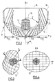
- FIG. 1 also shows the vertical projection, in the xOy plane, of the paths of the light rays coming from the light source 12 and reflected by different points of the reflector 10, and in FIG. 2 the horizontal projection of the paths of the light rays from the light source 12 and reflected by different points of the reflector 10.
- Figure 2 shows a vertical sectional view of the reflector of Figure 1, without the direct light cover nor closing glass. More specifically, Figure 2 is a vertical section view, along a plane parallel to the Oz axis, and containing a ray reflected by the reflector 10, and thus forming an angle ⁇ with the axis Ox.
- O'x 'and O'z' represent the projections of the axes Ox and Oz in the plane of this Figure, as well as 12 'represents the projection of the light source 12 in the plane of this Figure, and that the rays light from the source 12 and incidents on the reflector 10 are shown in dotted lines.
- the reflector 10 consists of two half-parabolas 10 H and 10 B.
- the upper half-dish 10 H has its focus F H located at the rear of the light source 12, and the lower half-dish 10 B has its focus F B located at the front of the light source 12.
- the two half -parables 10 H and 10 B present at any point with coordinates x, y, z, and in particular in the median plane x'Oy for points with coordinates x, y, 0, second order continuity in z, c ' that is to say that the planes tangent to the reflecting surface at any point with coordinates x, y, z vary continuously for any variation of the only variable z.
- the present invention also applies to the case where the half-parabolas 10 H and 10 B have “piloted” foci, that is to say that they constitute quasi-parabolas whose focal point F H and F B occupies on the 'axis Ox a position which is a function of the angle ⁇ , the projection of which on a vertical plane such as that of Figure 2 is represented by ⁇ ', under which a light ray is emitted by the light source 12, relative to the Ox axis.
- the reflector has, in horizontal section along the median plane xOy, a second order discontinuity, i.e. on either side of the plane xOz, the planes tangent to the reflecting surface form a non-zero angle, and moreover they are symmetrical with respect to the median plane xOz.
- the angle ⁇ of the light rays emitted by the light source 12 increases relative to the axis Ox, that is to say as the point of incidence of these rays on the reflector 10 moves away from the Ox axis, the angle, relative to the Ox axis, of the rays reflected by the part 10 d1 of the reflector 10 decreases, until it vanishes, the reflected light rays then being parallel to the Ox axis, and contribute to forming the axial part of the beam, between + 5 ° and -5 °.
- the rays coming from the light source 12 and incident on the second part 10 d2 of the reflector 10 give rise to rays reflected to the left, whose angle relative to the axis Ox decreases further to pass from a zero value to a negative value.
- These light rays contribute to forming the part of the beam located on the left of Figure 5, the maximum deflection being of the order of -20 °, and initially converging.
- the light rays reflected by the end of the part 10 d2 furthest from the light source 12, undergoing a convergent deflection reach the glass 16 in its useful part, avoiding the glass base 18.
- the light source 12 is arranged so that its largest dimension is arranged along the axis Ox, it follows that the images of this source provided by the part 10 d1 of the reflector 10 and formed on a screen are vertical or quasi-vertical, while the images of the source provided by the part 10 d2 of the reflector 10 and formed on a screen are horizontal or quasi-horizontal. Sending the quasi-horizontal or horizontal images in the immediate vicinity of the projector axis and simultaneously the quasi-vertical images outside the vicinity of the projector axis contributes to meeting the new regulatory requirements, without being led to design a reflector of large dimensions, especially in the horizontal direction.
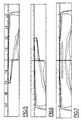
- the beam obtained after reflection on the entire right half of the reflector 10 consisting of the parts 10 d1 and 10 d2 is represented by its isolux curves, as they are illustrated in FIG. 5.
- the rays are emitted by the light source by forming an emission angle ⁇ with the longitudinal optical axis Ox and are reflected by the reflector by forming an emergence angle ⁇ with the longitudinal optical axis Ox, and that the emergence angle ⁇ is a decreasing monotonic function of the emission angle ⁇ .
- the present invention is not limited to the embodiment which has been described, but it is on the contrary likely to receive by the skilled person many variants that fall within its scope.
- This is how the invention can be implemented in headlamps for dipped beams, fog lamps, or headlamps signaling, located at the front or rear of the vehicle. In the latter case, we can plan that the upper and lower half-parabolas belong to the same parabola of revolution, and that the focus of this unique dish is located near the center of the light source.
Landscapes
- Engineering & Computer Science (AREA)
- General Engineering & Computer Science (AREA)
- Non-Portable Lighting Devices Or Systems Thereof (AREA)
Abstract
Description
- la Figure 1 représente schématiquement une coupe axiale horizontale d'un projecteur muni d'un réflecteur réalisé conformément à la présente invention ;
- la Figure 2 représente schématiquement une coupe verticale du réflecteur équipant le projecteur de la Figure 1 ;
- la Figure 3 représente une vue en perspective du réflecteur équipant le projecteur de la Figure 1 ;
- la Figure 4 représente une vue de face du réflecteur de la Figure 3 ;
- la Figure 5 représente des courbes isolux du faisceau obtenu par la moitié droite du réflecteur du projecteur de la Figure 1;
- la Figure 6 représente des courbes isolux du faisceau obtenu par la moitié gauche du réflecteur du projecteur de la Figure 1, et
- la Figure 7 représente des courbes isolux du faisceau obtenu par la totalité du réflecteur du projecteur de la Figure 1.
Claims (10)
- Réflecteur (10) pour dispositif d'éclairage ou de signalisation d'un véhicule automobile, destiné à être associé à une source lumineuse (12) pour former un faisceau lumineux de configuration prédéterminée autour d'un axe optique longitudinal (Ox), la source lumineuse (12) dont la plus grande dimension est disposée le long de 1' axe optique longitudinal (Ox), et émettant des rayons formant avec l'axe optique longitudinal (Ox) un angle d'émission (β), ces rayons étant réfléchis par le réflecteur (10) sous un angle d'émergence (γ) par rapport à l'axe optique longitudinal (Ox), le réflecteur (10) comprenant, de chaque côté d'un plan de symétrie central vertical (xOz) passant par l'axe optique longitudinal (Ox), une zone de réflexion (10d1, 10d2 ; 10g1, 10g2), les rayons réfléchis par la zone de réflexion (10d1, 10d2 ; 10g1, 10g2), à mesure que l'on s'éloigne du plan de symétrie central vertical (xOz), passant d'une première déviation maximale divergente à une deuxième déviation maximale convergente, caractérisé en ce que les rayons réfléchis par la zone de réflexion (10d1, 10d2 ; 10g1, 10g2) passent de la première déviation maximale à la deuxième déviation maximale de manière progressive et continue.
- Réflecteur selon la revendication 1, caractérisé en ce que, dans une zone de réflexion (10d1, 10d2 ; 10g1, 10g2), l'angle d'émergence (γ) est une fonction monotone continûment décroissante de l'angle d'émission (β).
- Réflecteur selon la revendication 2, caractérisé en ce que la fonction monotone continûment décroissante est linéaire.
- Réflecteur selon la revendication 1, caractérisé en ce qu'il comporte, de chaque côté d'un plan central horizontal (xOy) perpendiculaire au plan de symétrie central vertical (xOz), une surface dont la section (10H, 10B) par un plan vertical contenant un rayon réfléchi par cette surface est une parabole, dont le foyer (FH, FB) est situé au voisinage de la source lumineuse (12).
- Réflecteur selon la revendication 1, caractérisé en ce qu'il comporte, de chaque côté d'un plan central horizontal (xOy) perpendiculaire au plan de symétrie central vertical (xOz), une surface dont la section (10H, 10B) par un plan vertical contenant un rayon réfléchi par cette surface est une quasi-parabole, dont le foyer (FH, FB) est situé au voisinage de la source lumineuse (12), dans une position qui est une fonction de l'angle (δ), par rapport à l'axe optique longitudinal (Ox), sous lequel un rayon lumineux est émis par la source lumineuse (12).
- Réflecteur selon l'une des revendications précédentes, caractérisé en ce que les zones (10d1, 10g1) du réflecteur (10) situées de part et d'autre du plan de symétrie central vertical (xOz) présentent une discontinuité du second ordre, les plans tangents à ces zones de part et d'autre du plan de symétrie central vertical (xOz) formant un angle non nul et étant symétriques par rapport au plan de symétrie central vertical (xOz).
- Projecteur pour véhicule automobile, comportant une source lumineuse (12), un réflecteur (10), un cache de lumière directe (14) et une glace de fermeture (16), caractérisé en ce que le réflecteur (10) est conforme à l'une quelconque des revendications précédentes.
- Projecteur selon la revendication 7, caractérisé en ce que la glace de fermeture (16) est lisse ou faiblement déviatrice.
- Feu de signalisation pour véhicule automobile, comportant une source lumineuse (12), un réflecteur (10), un cache de lumière directe (14) et une glace de fermeture (16), caractérisé en ce que le réflecteur (10) est conforme à l'une quelconque des revendications 1 à 6.
- Feu de signalisation selon la revendication 9, caractérisé en ce que la glace de fermeture (16) est lisse ou faiblement déviatrice.
Applications Claiming Priority (2)
| Application Number | Priority Date | Filing Date | Title |
|---|---|---|---|
| FR0003154A FR2806151B1 (fr) | 2000-03-13 | 2000-03-13 | Reflecteur pour un dispositif d'eclairage ou de signalisation de vehicule automobile, et projecteur ou feu de signalisation comportant un tel reflecteur |
| FR0003154 | 2000-03-13 |
Publications (1)
| Publication Number | Publication Date |
|---|---|
| EP1134485A1 true EP1134485A1 (fr) | 2001-09-19 |
Family
ID=8847995
Family Applications (1)
| Application Number | Title | Priority Date | Filing Date |
|---|---|---|---|
| EP01400614A Withdrawn EP1134485A1 (fr) | 2000-03-13 | 2001-03-09 | Réflecteur pour un dispositif d'éclairage ou de signalisation de véhicule automobile, et projecteur ou feu de signalisation comportant un tel réflecteur |
Country Status (2)
| Country | Link |
|---|---|
| EP (1) | EP1134485A1 (fr) |
| FR (1) | FR2806151B1 (fr) |
Citations (9)
| Publication number | Priority date | Publication date | Assignee | Title |
|---|---|---|---|---|
| US1480364A (en) * | 1924-01-08 | Reflector | ||
| US1558270A (en) * | 1924-08-27 | 1925-10-20 | Walter F Morrison | Reflector for light projectors |
| FR2609148A1 (fr) | 1986-12-30 | 1988-07-01 | Cibie Projecteurs | Projecteur de vehicule automobile comportant un reflecteur a surface complexe a fond modifie |
| FR2609146A1 (fr) | 1986-12-30 | 1988-07-01 | Cibie Projecteurs | Projecteur de vehicule automobile comportant un reflecteur parabolique a fond modifie |
| US4825344A (en) * | 1986-02-20 | 1989-04-25 | Stanley Electric Co., Ltd. | Headlamp for vehicles |
| EP0341638A2 (fr) * | 1988-05-09 | 1989-11-15 | Ichikoh Industries Limited | Projecteur pour automobiles |
| FR2634003A1 (fr) | 1988-07-05 | 1990-01-12 | Cibie Projecteurs | Projecteur de vehicule automobile a reflecteur multi-zones et procede de lissage d'un tel reflecteur |
| EP0371510A2 (fr) | 1988-11-30 | 1990-06-06 | Ichikoh Industries Limited | Phare pour véhicules automobiles |
| DE19745467A1 (de) | 1997-10-15 | 1999-04-22 | Bosch Gmbh Robert | Scheinwerfer für Fahrzeuge |
-
2000
- 2000-03-13 FR FR0003154A patent/FR2806151B1/fr not_active Expired - Fee Related
-
2001
- 2001-03-09 EP EP01400614A patent/EP1134485A1/fr not_active Withdrawn
Patent Citations (9)
| Publication number | Priority date | Publication date | Assignee | Title |
|---|---|---|---|---|
| US1480364A (en) * | 1924-01-08 | Reflector | ||
| US1558270A (en) * | 1924-08-27 | 1925-10-20 | Walter F Morrison | Reflector for light projectors |
| US4825344A (en) * | 1986-02-20 | 1989-04-25 | Stanley Electric Co., Ltd. | Headlamp for vehicles |
| FR2609148A1 (fr) | 1986-12-30 | 1988-07-01 | Cibie Projecteurs | Projecteur de vehicule automobile comportant un reflecteur a surface complexe a fond modifie |
| FR2609146A1 (fr) | 1986-12-30 | 1988-07-01 | Cibie Projecteurs | Projecteur de vehicule automobile comportant un reflecteur parabolique a fond modifie |
| EP0341638A2 (fr) * | 1988-05-09 | 1989-11-15 | Ichikoh Industries Limited | Projecteur pour automobiles |
| FR2634003A1 (fr) | 1988-07-05 | 1990-01-12 | Cibie Projecteurs | Projecteur de vehicule automobile a reflecteur multi-zones et procede de lissage d'un tel reflecteur |
| EP0371510A2 (fr) | 1988-11-30 | 1990-06-06 | Ichikoh Industries Limited | Phare pour véhicules automobiles |
| DE19745467A1 (de) | 1997-10-15 | 1999-04-22 | Bosch Gmbh Robert | Scheinwerfer für Fahrzeuge |
Also Published As
| Publication number | Publication date |
|---|---|
| FR2806151A1 (fr) | 2001-09-14 |
| FR2806151B1 (fr) | 2002-05-10 |
Similar Documents
| Publication | Publication Date | Title |
|---|---|---|
| EP3147557B1 (fr) | Element optique primaire pour module lumineux de vehicule automobile | |
| EP1605201A1 (fr) | Dispositif d'éclairage et/ou de signalisation à guide optique pour véhicule automobile | |
| FR2863038A1 (fr) | Phare de vehicule a trois reflecteurs | |
| FR2823833A1 (fr) | Phare de vehicule destine a emettre plusieurs faisceaux | |
| FR2868510A1 (fr) | Lampe d'eclairage a diodes electroluminescentes pour vehicule | |
| EP3002504A2 (fr) | Module lumineux pour l'éclairage et/ou la signalisation d'un véhicule automobile | |
| FR3023600A1 (fr) | Module lumineux d'un vehicule automobile | |
| FR3004786A1 (fr) | Lentille, module optique et dispositif d'eclairage et/ou de signalisation pour vehicule automobile | |
| EP0256930B1 (fr) | Projecteur antibrouillard à filament transversal pour véhicule automobile | |
| WO2014001687A1 (fr) | Procédé de définition d'une lentille asphérique et module d'éclairage pour projecteur de véhicule automobile comportant une telle lentille | |
| FR3057939A1 (fr) | Unite optique comprenant un reflecteur rotatif pour feu de vehicule | |
| FR2745365A1 (fr) | Feu de signalisation a moyens perfectionnes d'etalement de la lumiere | |
| EP0645578B1 (fr) | Projecteur à glace lisse, notamment pour véhicule automobile, et procédé de fabrication du réflecteur d'un tel projecteur | |
| EP3453955B1 (fr) | Module lumineux pour l'eclairage et/ou la signalisation d'un vehicule automobile | |
| EP2926049B1 (fr) | Dispositif de signalisation pour véhicule avec effet tridimensionnel | |
| FR2609146A1 (fr) | Projecteur de vehicule automobile comportant un reflecteur parabolique a fond modifie | |
| EP1489351B1 (fr) | Projecteur de véhicule automobile permettant d'assurer au moins deux fonctions | |
| EP3124853B1 (fr) | Dispositif d'éclairage et/ou de signalisation pour véhicule | |
| EP1488954A1 (fr) | Système d'éclairage ou de signalisation pour véhicule automobile | |
| EP0648972B1 (fr) | Luminaire à optique orientable | |
| FR2806151A1 (fr) | Reflecteur pour un dispositif d'eclairage ou de signalisation de vehicule automobile, et projecteur ou feu de signalisation comportant un tel reflecteur | |
| EP1739345B1 (fr) | Module optique pour véhicule automobile | |
| FR3039625A1 (fr) | Dispositif d'eclairage pour vehicule automobile | |
| FR3002304A1 (fr) | Lentille, notamment pour une unite optique | |
| FR3074261A1 (fr) | Reflecteur pour dispositif d'eclairage |
Legal Events
| Date | Code | Title | Description |
|---|---|---|---|
| PUAI | Public reference made under article 153(3) epc to a published international application that has entered the european phase |
Free format text: ORIGINAL CODE: 0009012 |
|
| AK | Designated contracting states |
Kind code of ref document: A1 Designated state(s): AT BE CH CY DE DK ES FI FR GB GR IE IT LI LU MC NL PT SE TR Kind code of ref document: A1 Designated state(s): AT BE DE ES GB IT |
|
| AX | Request for extension of the european patent |
Free format text: AL;LT;LV;MK;RO;SI |
|
| AKX | Designation fees paid | ||
| REG | Reference to a national code |
Ref country code: DE Ref legal event code: 8566 |
|
| 17P | Request for examination filed |
Effective date: 20020320 |
|
| RBV | Designated contracting states (corrected) |
Designated state(s): AT BE DE ES GB IT |
|
| RBV | Designated contracting states (corrected) |
Designated state(s): AT BE DE ES GB IT |
|
| 17Q | First examination report despatched |
Effective date: 20060810 |
|
| STAA | Information on the status of an ep patent application or granted ep patent |
Free format text: STATUS: THE APPLICATION IS DEEMED TO BE WITHDRAWN |
|
| 18D | Application deemed to be withdrawn |
Effective date: 20070221 |