EP1134471A2 - Electromagnetic driving device for a fluid control valve - Google Patents
Electromagnetic driving device for a fluid control valve Download PDFInfo
- Publication number
- EP1134471A2 EP1134471A2 EP01106551A EP01106551A EP1134471A2 EP 1134471 A2 EP1134471 A2 EP 1134471A2 EP 01106551 A EP01106551 A EP 01106551A EP 01106551 A EP01106551 A EP 01106551A EP 1134471 A2 EP1134471 A2 EP 1134471A2
- Authority
- EP
- European Patent Office
- Prior art keywords
- movable element
- ring portion
- housing portion
- attracting
- coil
- Prior art date
- Legal status (The legal status is an assumption and is not a legal conclusion. Google has not performed a legal analysis and makes no representation as to the accuracy of the status listed.)
- Granted
Links
- 239000012530 fluid Substances 0.000 title claims description 15
- 230000004907 flux Effects 0.000 claims abstract description 22
- 230000000149 penetrating effect Effects 0.000 claims abstract description 8
- 239000011347 resin Substances 0.000 claims description 23
- 229920005989 resin Polymers 0.000 claims description 23
- 238000004519 manufacturing process Methods 0.000 claims description 16
- 230000000903 blocking effect Effects 0.000 claims description 10
- 238000000465 moulding Methods 0.000 claims description 5
- 230000001939 inductive effect Effects 0.000 claims description 4
- 238000009792 diffusion process Methods 0.000 claims description 3
- 239000000126 substance Substances 0.000 claims description 2
- 238000003754 machining Methods 0.000 abstract description 9
- 239000003921 oil Substances 0.000 description 23
- 239000000696 magnetic material Substances 0.000 description 16
- 230000005855 radiation Effects 0.000 description 7
- 230000007423 decrease Effects 0.000 description 5
- 239000010720 hydraulic oil Substances 0.000 description 5
- 230000001965 increasing effect Effects 0.000 description 4
- 238000000034 method Methods 0.000 description 4
- 230000005540 biological transmission Effects 0.000 description 3
- 238000004891 communication Methods 0.000 description 3
- 238000005096 rolling process Methods 0.000 description 3
- 238000005482 strain hardening Methods 0.000 description 3
- 238000004804 winding Methods 0.000 description 3
- 230000004048 modification Effects 0.000 description 2
- 238000012986 modification Methods 0.000 description 2
- 238000003892 spreading Methods 0.000 description 2
- 230000007480 spreading Effects 0.000 description 2
- 238000002347 injection Methods 0.000 description 1
- 239000007924 injection Substances 0.000 description 1
- 238000002844 melting Methods 0.000 description 1
- 230000008018 melting Effects 0.000 description 1
- 238000003825 pressing Methods 0.000 description 1
- 230000009467 reduction Effects 0.000 description 1
- XLYOFNOQVPJJNP-UHFFFAOYSA-N water Substances O XLYOFNOQVPJJNP-UHFFFAOYSA-N 0.000 description 1
Images


Classifications
-
- F—MECHANICAL ENGINEERING; LIGHTING; HEATING; WEAPONS; BLASTING
- F16—ENGINEERING ELEMENTS AND UNITS; GENERAL MEASURES FOR PRODUCING AND MAINTAINING EFFECTIVE FUNCTIONING OF MACHINES OR INSTALLATIONS; THERMAL INSULATION IN GENERAL
- F16K—VALVES; TAPS; COCKS; ACTUATING-FLOATS; DEVICES FOR VENTING OR AERATING
- F16K31/00—Actuating devices; Operating means; Releasing devices
- F16K31/02—Actuating devices; Operating means; Releasing devices electric; magnetic
- F16K31/04—Actuating devices; Operating means; Releasing devices electric; magnetic using a motor
-
- F—MECHANICAL ENGINEERING; LIGHTING; HEATING; WEAPONS; BLASTING
- F16—ENGINEERING ELEMENTS AND UNITS; GENERAL MEASURES FOR PRODUCING AND MAINTAINING EFFECTIVE FUNCTIONING OF MACHINES OR INSTALLATIONS; THERMAL INSULATION IN GENERAL
- F16K—VALVES; TAPS; COCKS; ACTUATING-FLOATS; DEVICES FOR VENTING OR AERATING
- F16K31/00—Actuating devices; Operating means; Releasing devices
- F16K31/02—Actuating devices; Operating means; Releasing devices electric; magnetic
- F16K31/06—Actuating devices; Operating means; Releasing devices electric; magnetic using a magnet, e.g. diaphragm valves, cutting off by means of a liquid
- F16K31/0603—Multiple-way valves
- F16K31/061—Sliding valves
- F16K31/0613—Sliding valves with cylindrical slides
-
- Y—GENERAL TAGGING OF NEW TECHNOLOGICAL DEVELOPMENTS; GENERAL TAGGING OF CROSS-SECTIONAL TECHNOLOGIES SPANNING OVER SEVERAL SECTIONS OF THE IPC; TECHNICAL SUBJECTS COVERED BY FORMER USPC CROSS-REFERENCE ART COLLECTIONS [XRACs] AND DIGESTS
- Y10—TECHNICAL SUBJECTS COVERED BY FORMER USPC
- Y10T—TECHNICAL SUBJECTS COVERED BY FORMER US CLASSIFICATION
- Y10T137/00—Fluid handling
- Y10T137/8593—Systems
- Y10T137/86493—Multi-way valve unit
- Y10T137/86574—Supply and exhaust
- Y10T137/8667—Reciprocating valve
- Y10T137/86694—Piston valve
- Y10T137/8671—With annular passage [e.g., spool]
Definitions
- the present invention relates to an electromagnetic driving device in which a housing portion receiving a movable element and an attracting portion attracting the movable element are integrally formed, a fluid control valve having the electromagnetic driving device and a method of manufacturing the electromagnetic driving device.
- axial centers of the housing portion and the attracting portion are likely to be offset due to their assembly errors. Therefore, not to disturb a reciprocal movement of the movable element even if the axial centers of the housing and attracting portions are offset to a certain extent, radial air gaps between the housing portion and the movable element and between the attracting portion and the movable element are larger by an offset amount of the axial centers thereof. Since larger air gap causes a reduction of attracting force, a more coil winding turn is required to secure a predetermined attracting force. Increasing the coil winding turn makes a body of the electromagnetic driving device larger.
- JP-A-11-500509 and JP-A-7-189852 To eliminate the offset of the axial centers of the housing and attracting portions, as disclosed in JP-A-11-500509 and JP-A-7-189852, is known an electromagnetic driving device in which the housing and attracting portions are integrally formed, for example, by machining.
- the housing and attracting portions are integrally formed, magnetic flux generated upon energizing the coil are likely to pass directly between the housing portion and the attracting portion, not through the moving element so that the attracting force is limited.
- a valve disclosed in JP-A-11-500509 is provided between the housing and attracting portions with a thin thickness throttling portion having a narrow area through which magnetic flux pass for enlarging magnetic resistance.
- the throttling portion serves to limit the magnetic flux passing directly between the housing portion and the attracting portion so that the attracting force of the movable element may be secured.
- the thickness of the throttling portion has to be remarkably thin. Thinner the thickness, a mechanical strength of the throttle portion is weaker so that the housing portion may be damaged.
- an electromagnetic actuator disclosed in JP-A-7-189852 is provided in a part of the housing portion with a non-magnetic material portion for enlarging the magnetic resistance.
- the non-magnetic material portion is formed by diffusing the non-magnetic material, for example, by laser radiation, a surface of the non-magnetic material portion tends to be rough.
- the non-magnetic portion in the actuator disclosed in JP-A-7-189852 is not in slidable contact with the moving element, the movement of the movable element is not disturbed even if an inner circumferential wall of the non-magnetic portion is rough.
- the rough surface of the non-magnetic portion causes likely to disturb a smooth movement of the movable element.
- An object of the invention is to provide an electromagnetic driving device that is compact and generates a large attracting force without damaging a housing portion of a fixing core.
- an electromagnetic driving device having a coil, a movable element, and a fixing element having a housing portion in which the movable element is housed to reciprocatingly move, and an attracting portion toward which the movable element is attracted by magnetic flux to be generated upon energizing the coil
- the housing portion is provided at a position radially opposed to the movable element with a ring portion, and the housing portion and the attracting portion are integrally formed.
- the ring portion is provided with at least one of through-holes radially penetrating a wall thereof.
- the housing and attracting portions are integrally formed and worked continuously by machining. Accordingly, the offset of the axial centers of the housing and attracting portions may be eliminated. This will result in minimizing radial air gaps between the housing portion and the movable element and between the attracting portion and the movable element so that an attracting force between the attracting portion and the movable element may be increased.
- one or more through-holes are formed to enlarge magnetic resistance of the ring portion so that magnetic flux flowing directly between the integrally formed housing and attracting portions is limited.
- the magnetic resistance may be increased by adjusting a number and each diameter of the through-holes without reducing a thickness of the ring portion. Therefore, a mechanical strength of the housing portion is assured and the housing portion is prevented from being damaged.
- the ring portion may be provided on inner or outer circumferential surface with one or more recesses or ring shaped grooves for enlarging magnetic resistance of the ring portion.
- the magnetic resistance may be increased by adjusting a number, each depth and largeness (width) of the recesses or ring shaped grooves without reducing a thickness of the ring portion.
- the ring portion may be provided on an outer circumferential surface with a non-magnetic diffusion layer. Since non-magnetic material is not diffused on an inner circumferential surface of the ring portion, the inner circumferential surface of the ring portion is not rough but smooth so that a smooth slidable movement between the movable element and the ring portion may be assured.
- the ring portion may be provided with a non-magnetic substance formed by inducing strains in metallographycal structure of the ring portion, for example, based on work hardening by pressing.
- a thickness of the wall of the ring portion is thinner that that of the housing portion axially adjacent thereto to an extent that a mechanical strength of the ring portion is not damaged practically. This will contribute to enlarge magnetic resistance of the ring portion, too.
- the magnetic driving device As a method of manufacturing the magnetic driving device, it is preferable that after forming one or more through-holes radially penetrating a wall of the ring portion, resin molding is executed on an outer circumferential surface of the fixing core including the ring portion, while the through-hole is closed with a blocking member abutting on an inner circumferential wall of the ring portion. As a result, resin is not leaked via the through-hole to an inside of the ring portion.
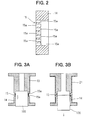
- Fig. 1 shows a fluid control valve according to a first embodiment of the present invention.
- the fluid control valve 1 is a spool type hydraulic control valve for controlling operating oil to be supplied to a hydraulic control apparatus of an automatic transmission for a vehicle.
- a linear solenoid 10 which serves as an electromagnetic driving device, is composed of a cylindrical yoke 11, an end plate 12, a fixing core 13, a plunger 17, a shaft 18 and a coil 20.
- the yoke 11, the end plate 12 and the fixing core 13 constitute a fixing element and the plunger 17 and the shaft 18 constitute a movable element.
- the yoke 11, the end plate 12, the fixing core 13 and plunger 17 are made of magnetic material.
- the fixing core 13 is fixed between the end plate 12 and a spool housing 31, in which a spool 30 is slidably and reciprocatingly held, in such a manner that both ends of the yoke 11 crimp the respective circumferential peripheries of the spool housing 31 and the end plate 12.
- the fixing core has a housing portion 14, in which the plunger is housed so as to reciprocatingly move, and an attracting portion 16, which generates a magnetic attracting force for attracting the plunger 17.
- an inner circumferential surface of the housing portion 14 or an outer circumferential surface of the plunger is coated or plated with non-magnetic material.
- the housing portion 14 is provided at a position facing radially the plunger 17 with a ring portion 15.
- the ring portion 15 is formed by machining in a ring shape an outer circumferential wall of the housing portion 14. A thickness of the ring portion 15 is thinner than that of the housing portion 14 axially adjacent thereto to an extent that a required mechanical strength of the housing portion 14 is not damaged.
- the ring portion 15 is provided with a plurality of radially penetrating through-holes 15a. As the ring portion 15 is thin and has a plurality of the through-holes 15a, an area of the ring portion 15 through which magnetic flux pass is narrowed and limited.
- the through-holes 15a are provided by laser radiation, machining, press working or water jet working.
- the attracting portion 16 has an opposing portion 16a, which is axially opposed to the plunger 17, and a taper portion 16b, which is located between the opposing portion 16a and the ring portion 15 and whose diameter is smaller toward the opposing portion 16a.
- the plunger 17 is provided at an end thereof on a side of the opposing portion 16a with a taper portion 17a whose diameter is smaller toward the attracting portion 19.
- the shaft 18 is press fitted into the plunger 17 and moves reciprocatingly together with the plunger 17. An end of the shaft 18 abuts on an end of the spool 30.
- the coil 20 is formed in a cylindrical shape by resin molding and fixed by the yoke 11 and the fixing core 13.
- a terminal not shown
- magnetic flux flows through a magnetic circuit constituted by the yoke 11, the plunger 17 and the fixing core 13 so that an attracting force is generated between the attracting portion 16 of the fixing core 13 and the plunger 17. Accordingly, the plunger 17 and the shaft 18 move downward in Fig. 1.
- the downward movement of the plunger 17 in Fig. 1 is restricted by a stopper 19.
- the spool housing 31 holds the spool 30 so that the spool 30 moves reciprocatingly therein.
- the spool housing 31 is provided with an input port 32, an output port 33, a feedback port 34 and an ejecting port 35.
- Operating oil is supplied and input to the input port 32 by a pump from a tank (not shown).
- the operating oil is supplied to an engaging device of an automatic trans mission (not shown) from the output port 33.
- the output port 33 is in communication with the feedback port 34 at a portion outside the fluid control valve 1 so that a part of operating oil flew out from the output port 33 is introduced to the feedback port 34.
- the feedback port 34 is in communication with a feedback chamber 36.
- the operating oil is ejected from the ejecting port 35 to the tank.
- the spool 30 is provided in order from an opposite side of the linear solenoid valve 10 with a large diameter land 37, a large diameter land 38 and a small diameter land 39.
- a diameter of the small diameter land 39 is smaller than that of the large diameter land 37 or 38.
- the spool 30 is always in contact with the shaft 18 of the linear solenoid 10. The movement of the plunger 17 is transmitted via the shaft 18 to the spool so that the spool 30 moves reciprocatingly in the spool housing 31.
- a spring 40 which is disposed on an opposite side of the linear solenoid 10 and serves as biasing means, urges the spool 30 toward the linear solenoid 10.
- the feedback chamber 36 is located between the large diameter land 38 and the small diameter land 39 to each of which a force responsive to an outer diameter thereof due to hydraulic oil in the feedback chamber 38 is applied. Accordingly, the hydraulic oil in the feedback chamber 38 urges the spool 30 in an opposite direction of the linear solenoid 10 . Feedback of a part of the hydraulic oil output by the fluid control valve 1 serves to prevent output pressure from fluctuating due to a fluctuation of hydraulic pressure to be supplied or input.
- the spool 30 is at rest at a position where the biasing force of the spring 40 is balanced with a force of plunger 17 urging the spool 30 due to the electromagnetic attracting force generated in the fixing core 13 based on the current supplied to the coil and a force which the spool 30 receives from the hydraulic oil in the feedback chamber 36.
- An amount of operating oil flowing from the input port 32 to the output port 33 depends on a seal length representing a length by which the an inner circumferential wall 31a of the spool housing 31 and an outer circumferential wall of the large diameter land 38 overlap each other. As the seal length is shorter, the amount of operating oil flowing from the input port 32 to the output port 33 more increases. On the contrary, as the seal length is longer, the amount of operating oil flowing from the input port 32 to the output port 33 more decreases. Similarly, an amount of operating oil flowing from the output port 33 to the ejecting port 35 depends on the seal length with respect to an inner circumferential wall 31b of the spool housing 31 and an outer circumferential wall of the large diameter land 37.
- the spool 30 is at rest at a position where the biasing force of the spring 40 is balanced with a feedback force of the hydraulic oil.
- the input port 32 is in communication with the output port and the amount of operating oil flowing from the input port 32 to the output port 33 more increases. As the ejecting port 35 is closed so that hydraulic pressure of the operating oil supplied to the automatic transmission shows maximum.
- the magnetic flux flowing between the housing and attracting portions 14 and 16 is limited since the ring portion 15 acts as the magnetic resistance. Accordingly, the magnetic flux flows between the housing portion 14 and the plunger 17 and between the taper portions 17a of the plunger 17 and 16b of the attracting portion 16. The magnetic flux passing directly between the housing and the attracting portions 14 and 16 not via the plunger 17 but via the ring portion 15 does not exert a force of attracting the plunger 17. As the magnetic flux is prevented from flowing directly between the housing and the attracting force 14 and 16, the force of attracting the plunger 17 more increases.
- the plunger 17 Upon energizing the coil 20, the plunger 17 is attracted to the attracting portion 16 against the biasing force of the spring 40 so that the spool 30 moves downward in Fig. 1.
- the seal length with respect to the inner circumferential wall 31a and the larger diameter land 38 becomes longer and the inner circumferential wall 31b and the large diameter land 37 becomes shorter, the amount of operating oil flowing from the input port 32 to the output port 33 more decreases and the amount of operating oil flowing from the output port 33 to the ejecting port 35 more increases . Accordingly, hydraulic pressure of the operating oil flew out from the output port 33 decreases.
- the linear solenoid 10 is operative to adjust a force of urging the spool 30 toward the linear solenoid 10 by controlling current to be supplied to the coil 20 so that hydraulic pressure of operating oil flew out from the output port 33 is adjusted.
- the electromagnetic attracting force of the attracting portion 16 increases in proportion to the current amount so that an urging force of the shaft 18 for moving the spool 30 in an opposite direction to the linear solenoid 10.
- the spool 30 comes at rest at a position where the force acting from the plunger 17 to the spool 30 due to the electromagnetic attracting force and the force of urging the spool 30 in an opposite direction to the linear solenoid 10 due to the hydraulic pressure of feed backed operating oil are balanced with the biasing force of the spring 40. Accordingly, the hydraulic pressure of operating oil flew out from the output port 33 decreases in proportion to the amount of current supplied to the coil 20.
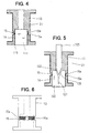
- a first modified method of manufacturing the inner circumference spool 21 is described with reference to Fig. 4.
- operating oil 111 is supplied to an inside of a cylindrical cap member 110 and a cylindrical side wall of the cylindrical cap member is held inside the housing portion 14 by hydraulic pressure of operating oil 111 so that a resin leakage from the through-holes 15a is prevented.
- the cylindrical cap member 110 and the operating oil 111 constitute the blocking member.
- a second modified method of manufacturing the inner circumference spool 21 is described with reference to Figs . 5 and 6.
- the blocking member serves to close the through-holes 15a to prevent the resin for forming the inner circumference spool 21 from being leaked from the trough-holes 15. Accordingly, the resin never disturbs a reciprocal movement of the plunger 17. Further, the blocking member not only closes the through-holes 15a but also supports the thin thickness ring portion 15 from an inside thereof so that the ring portion 15 is prevented from deforming due to pressure to be generated when the resin hardens.
- the method of manufacturing the inner circumference spool 21 mentioned above is applicable not only to the first embodiment in which the through-holes 15a are formed in the ring portion 15 but also any of second to fifth embodiments hereinafter.
- FIG. 7 A second embodiment of the present invention is described with reference to Fig. 7. Substantially same structure and portions as the first embodiment are affixed with the same reference numbers thereof.
- an outer circumferential wall of the ring portion 15 has a plurality of recesses 50.
- the recesses 50 are formed by laser radiation, form rolling or press working.
- the recesses 50 on the thin thickness ring portion 15 serves to reduce a magnetic circuit area and to enlarge a magnetic resistance.
- an outer circumferential wall of the ring portion 15 has a plurality of ring shaped grooves 55.
- the ring shaped grooves 55 are formed by laser radiation, machining or form rolling.
- the ring shaped grooves 55 on the thin thickness ring portion 15 serves to reduce a magnetic circuit area and to enlarge a magnetic resistance.
- the thin thickness ring portion 15 instead of forming the thin thickness ring portion 15 by machining the outer circumference thereof, the thin thickness ring portion 15 may be formed by machining an inner circumference thereof. Further, in the second or third embodiment, instead of forming the recesses 50 or the ring shaped grooves 55 on the outer circumference of the ring portion 15, the recesses 50 or the ring shaped grooves 55 are formed on an inner circumference or on both of inner and outer circumferences of the ring portion 15.
- a fourth embodiment of the present invention is described with reference to Fig. 9. Substantially same structure and portions as the first embodiment are affixed with the same reference numbers thereof.
- a non-magnetic diffusion layer 60 is provided in the thin thickness ring portion 15 by diffusing non-magnetic material to an outer circumference thereof to enlarge the magnetic resistance of the ring portion 15. As the non-magnetic material is not diffused to an inner circumference of the ring portion 15, an inner circumferential surface of the ring portion 15, which is in slidable contact with the movable element, is prevented from becoming rough. Accordingly, the movable element smoothly moves in the ring portion 15. The following methods may be contemplated for diffusing the non-magnetic material to the ring portion 15.
- a fourth embodiment of the present invention is described with reference to Fig. 10. Substantially same structure and portions as the first embodiment are affixed with the same reference numbers thereof.
- a non-magnetic portion 65 is formed to enlarge the magnetic resistance in the thin thickness ring shaped portion 15 by inducing strains in metallographical structure of the ring portion 15. The following methods may be contemplated for inducing the strains in metallographical structure of the ring portion 15.
- the radial air gap between the plunger 17 and the fixing element is small to a minimum extent.
- the thin thickness ring portion 15 has means for enlarging magnetic resistance as mentioned in the above embodiments, magnetic flux flowing directly between the housing and attracting portions 14 and 16 is limited. Accordingly, the attracting force to the plunger increases without enlarging the body of the electromagnetic driving device or the fluid control valve.
- the ring portion of the present invention can secure the same magnetic resistance as the conventional ring portion.
- the thicker ring portion serves to more increase the mechanical strength of the ring portion, which prevents the housing portion from being damaged.
- the ring portion 15 may be provided without forming the thin portion thereof by adjusting (1) a total number and each diameter of the through-holes, (2) a total number, each depth and each largeness of the recesses 50, (3) a total number, each width and each depth of the ring shaped grooves 55, (4) depth by which the non-magnetic material is diffused or (5) largeness of the strains.
- the electromagnetic driving device of the present invention is applicable not only to the electromagnetic driving apparatus having the spool type hydraulic control valve but also to any other type of electromagnetic driving apparatus having fluid control valve or device in which the attracting force to the movable element is larger without enlarging the body thereof.
- a fixing core (13) has a housing portion (14), in which a plunger (17) is housed to reciprocatingly move, and an attracting portion (16) toward which the plunger is attracted upon energizing a coil (20).
- the housing portion is provided with a ring portion (15), which is formed by machining an outer circumference wall thereof and whose thickness is thinner than that of a part of the housing portion adjacent to the ring portion to an extent that mechanical strength of the housing portion is not damaged practically.
- the ring portion is provided with a plurality of through-holes (15a) penetrating radially the wall thereof. Amagnetic flux area of the ring portion is limited due to the thin wall and the through-holes so that magnetic resistance is enlarged.
Landscapes
- Engineering & Computer Science (AREA)
- General Engineering & Computer Science (AREA)
- Mechanical Engineering (AREA)
- Magnetically Actuated Valves (AREA)
Abstract
Description
According to the third embodiment, an outer circumferential wall of the
Claims (10)
- An electromagnetic driving device comprising;a coil (20);a movable element (17,18); anda fixing element (11,12,13) having a housing portion (14) in which the movable element is housed to reciprocatingly move, and an attracting portion (16) toward which the movable element is attracted by magnetic flux to be generated upon energizing the coil, wherein the housing portion is provided at a position thereof radially opposed to the movable element with a ring portion (15), and the housing portion and the attracting portion are integrally formed, and, further,wherein the ring portion is provided with at least one of through-holes (15a) radially penetrating a wall thereof.
- An electromagnetic driving device comprising;a coil (20);a movable element (17,18); anda fixing element (11,12,13)having a housing portion (14) in which the movable element is housed to reciprocatingly move, and an attracting portion (16) toward which the movable element is attracted by magnetic flux to be generated upon energizing the coil, wherein the housing portion is provided at a position thereof radially opposed to the movable element with a ring portion (15), and the housing portion and the attracting portion are integrally formed, and, further,wherein the ring portion is provided on at least one of inner and outer circumferential surfaces with at least one of recesses (50).
- An electromagnetic driving device comprising;a coil (20);a movable element (17,18); anda fixing element (11,12,13)having a housing portion (14) in which the movable element is housed to reciprocatingly move, and an attracting portion (16)toward which the movable element is attracted by magnetic flux to be generated upon energizing the coil, wherein the housing portion is provided at a position radially opposed to the movable element with a ring portion (15), and the housing portion and the attracting portion are integrally formed, and, further,wherein the ring portion is provided on at least one of inner and outer circumferential surfaces with at least one of ring shaped grooves (55).
- An electromagnetic driving device comprising;a coil (20);a movable element (17,18); anda fixing element (11,12,13) having a housing portion (14) in which the movable element is housed to reciprocatingly move, and an attracting portion (16) toward which the movable element is attracted by magnetic flux to be generated upon energizing the coil, wherein the housing portion is provided at a position radially opposed to the movable element with a ring portion (15), and the housing portion and the attracting portion are integrally formed, and, further,wherein the ring portion is provided on an outer circumferential surface with a non-magnetic diffusion layer (60).
- An electromagnetic driving device comprising;a coil (20);a movable element (17,18); anda fixing element (11,12,13) having a housing portion (14) in which the movable element is housed to reciprocatingly move, and an attracting portion (16) toward which the movable element is attracted by magnetic flux to be generated upon energizing the coil, wherein the housing portion is provided at a position radially opposed to the movable element with a ring portion (15), and the housing portion and the attracting portion are integrally formed, and, further,wherein the ring portion is provided with a non-magnetic substance (65) formrd by inducing strains in metallographycal structure of the ring portion.
- An electromagnetic driving device according to any one of claims 1 to 5, wherein a thickness of the wall of the ring portion is thinner that that of a part of the housing portion axially adjacent thereto.
- A fluid control valve having the electromagnetic driving device according to any one of claims 1 to 5, further comprising:a cylindrical housing (31) having a plurality of ports (32,33,34,35) through which fluid flows;a spool (30) being reciprocatingly moved in the cylindrical housing along with the movable element for adjusting amounts of fluid flowing through the respective ports; andbiasing means (40) for urging the spool in an opposite direction to a direction in which the movable element is attracted to the attracting portion.
- A method of manufacturing an electromagnetic driving device having a coil (20) wound on a spool (21), a movable element (17,18), and a fixing element (11,12,13) having a housing portion (14) in which the movable element is housed to reciprocatinglymove, and an attracting portion (16) toward which the movable element is attracted by magnetic flux to be generated upon energizing the coil, wherein the housing portion is provided at a position radially opposed to the movable element with a ring portion (15), and the housing portion and the attracting portion are integrally formed, comprising steps of:forming at least one of through-holes (15a) radially penetrating a wall of the ring portion; andexecuting res in molding on an outer circumferential surface of the fixing core including the ring portion, while the through-hole is closed with a blocking member (100, 110&111, 120&125)abutting on an inner circumferential wall of the ring portion so that resin is not leaked via the through-hole to an inside of the ring portion.
- A method of manufacturing an electromagnetic driving device having a coil (20) wound on a spool (21), a movable element (17,18), and a fixing element (11,12,13) having a housing portion (14) in which the movable element is housed to reciprocatingly move, and an attracting portion (16) toward which the movable element is attracted by magnetic flux to be generated upon energizing the coil, wherein the housing portion is provided at a position radially opposed to the movable element with a ring portion (15), and the housing portion and the attracting portion are integrally formed, comprising steps of:making a radial thickness of the ring portion thinner than that of a part of the housing portion axially adjacent thereto; andexecuting resin molding on an outer circumferential surface of the fixing core including the ring portion, while the ring portion is supported by a blocking member (100,110%111,120&125) abutting on an inner circumferential wall of the ring portion so that the ring portion is prevented from deforming due to resin pressure.
- A method of manufacturing an electromagnetic driving device according to claim 9, further comprising steps of:
forming at least one of through-holes (15a) radially penetrating a wall of the ring portion, wherein the blocking member closes the through-hole so that resin is not leaked via the through-hole to an inside of the ring portion.
Applications Claiming Priority (2)
| Application Number | Priority Date | Filing Date | Title |
|---|---|---|---|
| JP2000075437A JP2001263521A (en) | 2000-03-17 | 2000-03-17 | Electromagnetic drive device, fluid control valve using the same, and method of manufacturing electromagnetic drive device |
| JP2000075437 | 2000-03-17 |
Publications (3)
| Publication Number | Publication Date |
|---|---|
| EP1134471A2 true EP1134471A2 (en) | 2001-09-19 |
| EP1134471A3 EP1134471A3 (en) | 2002-12-11 |
| EP1134471B1 EP1134471B1 (en) | 2004-05-12 |
Family
ID=18593333
Family Applications (1)
| Application Number | Title | Priority Date | Filing Date |
|---|---|---|---|
| EP01106551A Expired - Lifetime EP1134471B1 (en) | 2000-03-17 | 2001-03-15 | Electromagnetic driving device for a fluid control valve |
Country Status (5)
| Country | Link |
|---|---|
| US (1) | US6601822B2 (en) |
| EP (1) | EP1134471B1 (en) |
| JP (1) | JP2001263521A (en) |
| KR (1) | KR100442445B1 (en) |
| DE (1) | DE60103199T2 (en) |
Cited By (4)
| Publication number | Priority date | Publication date | Assignee | Title |
|---|---|---|---|---|
| EP1450380A1 (en) * | 2003-02-21 | 2004-08-25 | Toyoda Koki Kabushiki Kaisha | Electromagnetic drive device |
| EP1582791A1 (en) * | 2004-03-30 | 2005-10-05 | Toyoda Koki Kabushiki Kaisha | Solenoid valve |
| DE10222413B4 (en) * | 2001-05-22 | 2013-07-04 | Denso Corporation | Electromagnetic actuator |
| EP2631516A1 (en) * | 2012-02-22 | 2013-08-28 | Delphi Technologies, Inc. | Solenoid-actuated pressure control valve |
Families Citing this family (44)
| Publication number | Priority date | Publication date | Assignee | Title |
|---|---|---|---|---|
| JP4058604B2 (en) * | 2000-12-11 | 2008-03-12 | 株式会社デンソー | Solenoid valve device |
| DE10152172A1 (en) * | 2001-10-23 | 2003-04-30 | Bosch Gmbh Robert | magnetic valve |
| US6772791B2 (en) * | 2002-05-17 | 2004-08-10 | Mac Valves, Inc. | Directly operated pneumatic valve having an air assist return |
| JP2005188630A (en) * | 2003-12-25 | 2005-07-14 | Denso Corp | Solenoid valve device |
| US7001300B1 (en) * | 2004-02-20 | 2006-02-21 | Sonnax Industries, Inc. | Replacement solenoid switch valve assembly |
| JP2006140246A (en) * | 2004-11-11 | 2006-06-01 | Shinano Kenshi Co Ltd | Actuator |
| JP4596890B2 (en) | 2004-11-11 | 2010-12-15 | シナノケンシ株式会社 | Actuator |
| JP2006222199A (en) * | 2005-02-09 | 2006-08-24 | Isuzu Motors Ltd | Proportional solenoid and flow control valve using the same |
| JP2006234004A (en) * | 2005-02-22 | 2006-09-07 | Aisin Seiki Co Ltd | Solenoid valve and manufacturing method thereof |
| JP4618133B2 (en) * | 2006-01-06 | 2011-01-26 | 株式会社デンソー | solenoid valve |
| KR100819203B1 (en) * | 2007-06-25 | 2008-04-03 | 주식회사 유니크 | Proportional control solenoid valve for high flow control for direct transmission control of automatic transmission |
| CN101688623B (en) * | 2007-09-28 | 2012-01-25 | 三菱电机株式会社 | Solenoid valve |
| JP4525736B2 (en) * | 2007-11-09 | 2010-08-18 | 株式会社デンソー | Linear solenoid |
| JP4958008B2 (en) * | 2007-11-28 | 2012-06-20 | 株式会社デンソー | Electromagnetic drive device and fluid control valve using the same |
| JP2009275841A (en) * | 2008-05-15 | 2009-11-26 | Denso Corp | Linear solenoid |
| US8585014B2 (en) * | 2009-05-13 | 2013-11-19 | Keihin Corporation | Linear solenoid and valve device using the same |
| JP2011077355A (en) * | 2009-09-30 | 2011-04-14 | Keihin Corp | Linear solenoid and valve device using the same |
| WO2011050878A1 (en) * | 2009-10-26 | 2011-05-05 | Hydac Fluidtechnik Gmbh | Solenoid valve |
| US8690118B2 (en) * | 2010-01-08 | 2014-04-08 | Caterpillar Inc. | Solenoid actuated device and methods |
| KR101016189B1 (en) * | 2010-01-22 | 2011-02-24 | 주식회사 유니크 | Solenoid Valve for Transmission |
| EP2601659A1 (en) * | 2010-08-05 | 2013-06-12 | Fluid Automation Systems S.A. | Solenoid valve with a two-part core |
| JP5375847B2 (en) * | 2011-02-04 | 2013-12-25 | 株式会社デンソー | solenoid valve |
| EP2527944B1 (en) * | 2011-05-27 | 2020-11-25 | SVM Schultz Verwaltungs-GmbH & Co. KG | Electromagnetic pressure regulator |
| DE102011053023A1 (en) * | 2011-08-26 | 2013-02-28 | Hilite Germany Gmbh | Hydraulic transmission valve |
| WO2013172520A1 (en) * | 2012-05-14 | 2013-11-21 | Unick Corporation | Solenoid valve |
| KR101160470B1 (en) * | 2012-05-14 | 2012-06-27 | 주식회사 유니크 | Solenoid valve |
| KR101192166B1 (en) | 2012-05-14 | 2012-10-17 | 주식회사 유니크 | Solenoid valve |
| US9423045B2 (en) * | 2012-06-21 | 2016-08-23 | Borgwarner Inc. | Method for solenoid motor venting with contamination protection via a hydraulic sleeve |
| DE102013206959A1 (en) * | 2013-04-17 | 2014-10-23 | Robert Bosch Gmbh | Solenoid valve with improved opening and closing behavior |
| US9627121B2 (en) * | 2014-05-28 | 2017-04-18 | Flextronics Automotive, Inc. | Solenoid robust against misalignment of pole piece and flux sleeve |
| US11201005B2 (en) | 2016-06-28 | 2021-12-14 | Borg Warner Inc. | Solenoid having inverse tapered armature for solenoid-actuated valve |
| JP6729288B2 (en) * | 2016-10-21 | 2020-07-22 | 株式会社デンソー | Electromagnetic actuator |
| DE102018000269A1 (en) | 2017-02-25 | 2018-08-30 | Thomas Magnete Gmbh | Electromagnet and method of making the electromagnet |
| DE102017214506A1 (en) * | 2017-08-21 | 2019-02-21 | Robert Bosch Gmbh | Proportional valve for controlling a gaseous medium |
| JP6667114B2 (en) * | 2017-09-21 | 2020-03-18 | 株式会社アドヴィックス | solenoid valve |
| EP3776606B1 (en) | 2018-05-07 | 2025-02-26 | G.W. Lisk Company, Inc. | Single coil apparatus and method |
| JP7124485B2 (en) * | 2018-06-28 | 2022-08-24 | 日本電産トーソク株式会社 | Solenoid device |
| JP2020004844A (en) * | 2018-06-28 | 2020-01-09 | 日本電産トーソク株式会社 | Solenoid device |
| DE102019211004A1 (en) * | 2019-07-25 | 2021-01-28 | Festo Se & Co. Kg | Valve |
| EP4035191B1 (en) * | 2019-09-24 | 2025-12-24 | G.W. Lisk Company, Inc. | Method and apparatus for solenoid tube |
| WO2022071988A1 (en) * | 2020-10-01 | 2022-04-07 | G.W. Lisk Company, Inc. | Method and apparatus having a single coil with embedded magnets |
| NL2026778B1 (en) * | 2020-10-27 | 2022-06-21 | Suspension Res Innovation B V | A shock absorber/damper device with a solenoid operated valve element and a magnetic flux-bypass nose for influencing magnetic forces during switching operations. |
| DE102022118879A1 (en) * | 2022-07-27 | 2024-02-01 | Liebherr-Aerospace Lindenberg Gmbh | Valve and aircraft |
| US11608907B1 (en) * | 2022-08-19 | 2023-03-21 | Pipl Limited | Solenoid valve |
Family Cites Families (23)
| Publication number | Priority date | Publication date | Assignee | Title |
|---|---|---|---|---|
| US2853659A (en) | 1952-03-10 | 1958-09-23 | Herion Erich | Solenoid arrangements |
| US4233583A (en) * | 1978-09-22 | 1980-11-11 | Bicron Electronics Company | Flux shielded solenoid |
| US4486053A (en) | 1980-11-04 | 1984-12-04 | Clayton Dewandre Company Limited | Solenoid operated valves |
| JPS5792806A (en) | 1980-11-29 | 1982-06-09 | Ckd Controls Ltd | Oil immersed type solenoid |
| JPS60231588A (en) * | 1984-04-27 | 1985-11-18 | Kawamura Kogyo Kk | Method of laser cutting of new ceramic |
| JPS61168215A (en) | 1985-01-21 | 1986-07-29 | Diesel Kiki Co Ltd | Manufacturing method for plunger used in electromagnetic proportional solenoid |
| SE447853B (en) | 1986-02-05 | 1986-12-15 | Svab Specialventil Ab | AS THE FLUIDUM PRESSURE SEATER DESIGNED THE ELECTROMAGNET |
| US4919390A (en) * | 1987-12-29 | 1990-04-24 | Hitachi Construction Machinery Co., Ltd. | Solenoid operated valve apparatus |
| US4838954A (en) * | 1988-04-25 | 1989-06-13 | Asi Perach | Pressure regulator |
| IT1219397B (en) * | 1988-06-23 | 1990-05-11 | Weber Srl | VALVE FOR DOSING AND PULVERIZING ELECTROMAGNETICALLY OPERATED FUEL PROVIDED WITH DOUBLE SERIES OF SIDE HOLES FOR FUEL INLET |
| US4920009A (en) | 1988-08-05 | 1990-04-24 | General Motors Corporation | Method for producing laminated bodies comprising an RE-FE-B type magnetic layer and a metal backing layer |
| EP0407969B1 (en) * | 1989-07-14 | 1993-10-06 | MAHO Aktiengesellschaft | Process and device for manufacturing hollow spaces in workpieces using a laser beam |
| JPH073608Y2 (en) * | 1989-07-24 | 1995-01-30 | 津田駒工業株式会社 | solenoid |
| JP2662041B2 (en) * | 1989-07-28 | 1997-10-08 | 株式会社日立製作所 | Drilling method using laser beam and method for manufacturing nozzle of fuel injection valve using the same |
| US5218999A (en) * | 1990-05-17 | 1993-06-15 | Mitsubishi Denki K.K. | Solenoid valve |
| JP3024471B2 (en) | 1993-12-28 | 2000-03-21 | 三菱電機株式会社 | Electromagnetic actuator and method of manufacturing the same |
| DE19503821A1 (en) | 1995-02-06 | 1996-08-08 | Bosch Gmbh Robert | Electromagnetically actuated valve |
| JP3510383B2 (en) | 1995-05-29 | 2004-03-29 | カヤバ工業株式会社 | solenoid |
| US5608369A (en) * | 1995-07-25 | 1997-03-04 | Outboard Marine Corporation | Magnetic gap construction |
| JP4203612B2 (en) * | 1996-12-06 | 2009-01-07 | コンティネンタル・テーベス・アクチェンゲゼルシャフト・ウント・コンパニー・オッフェネ・ハンデルスゲゼルシャフト | Multiway valve |
| DE19727414A1 (en) * | 1997-06-27 | 1999-01-07 | Bosch Gmbh Robert | Method of manufacturing a solenoid for a valve and valve with a solenoid |
| DE19739324A1 (en) * | 1997-09-09 | 1999-03-11 | Bosch Gmbh Robert | Electromagnetically actuated valve |
| JP2000046225A (en) * | 1998-05-27 | 2000-02-18 | Aisin Seiki Co Ltd | Solenoid valve |
-
2000
- 2000-03-17 JP JP2000075437A patent/JP2001263521A/en active Pending
-
2001
- 2001-03-07 US US09/799,625 patent/US6601822B2/en not_active Expired - Lifetime
- 2001-03-13 KR KR10-2001-0012836A patent/KR100442445B1/en not_active Expired - Lifetime
- 2001-03-15 DE DE60103199T patent/DE60103199T2/en not_active Expired - Lifetime
- 2001-03-15 EP EP01106551A patent/EP1134471B1/en not_active Expired - Lifetime
Cited By (6)
| Publication number | Priority date | Publication date | Assignee | Title |
|---|---|---|---|---|
| DE10222413B4 (en) * | 2001-05-22 | 2013-07-04 | Denso Corporation | Electromagnetic actuator |
| EP1450380A1 (en) * | 2003-02-21 | 2004-08-25 | Toyoda Koki Kabushiki Kaisha | Electromagnetic drive device |
| US6922124B2 (en) | 2003-02-21 | 2005-07-26 | Toyoda Koki Kabushiki Kaisha | Electromagnetic drive device |
| EP1582791A1 (en) * | 2004-03-30 | 2005-10-05 | Toyoda Koki Kabushiki Kaisha | Solenoid valve |
| US7513272B2 (en) | 2004-03-30 | 2009-04-07 | Jtekt Corporation | Solenoid valve |
| EP2631516A1 (en) * | 2012-02-22 | 2013-08-28 | Delphi Technologies, Inc. | Solenoid-actuated pressure control valve |
Also Published As
| Publication number | Publication date |
|---|---|
| US6601822B2 (en) | 2003-08-05 |
| KR100442445B1 (en) | 2004-07-30 |
| EP1134471B1 (en) | 2004-05-12 |
| KR20010092280A (en) | 2001-10-24 |
| EP1134471A3 (en) | 2002-12-11 |
| US20010022474A1 (en) | 2001-09-20 |
| DE60103199D1 (en) | 2004-06-17 |
| JP2001263521A (en) | 2001-09-26 |
| DE60103199T2 (en) | 2005-06-23 |
Similar Documents
| Publication | Publication Date | Title |
|---|---|---|
| EP1134471B1 (en) | Electromagnetic driving device for a fluid control valve | |
| JP5125441B2 (en) | Linear solenoid device and solenoid valve | |
| JP4790441B2 (en) | Electromagnetic fuel injection valve and method of assembling the same | |
| US6615869B2 (en) | Solenoid valve | |
| DE10031231A1 (en) | Electromagnetic actuator, e.g. for vehicle transmission valve, has permanent magnet, provided in housing section, that generates a magnetic flow which is in the same direction as the magnetic flow generated by a coil | |
| US11435006B2 (en) | Electromagnetic actuating device | |
| KR20210064375A (en) | solenoid | |
| US20010015223A1 (en) | Directional seat valve | |
| JP2009030777A (en) | Linear solenoid | |
| JP5291548B2 (en) | Linear solenoid and valve device using the same | |
| KR102419248B1 (en) | Solenoid valve with adjustable spring force | |
| US11948737B2 (en) | Solenoid | |
| US20220285066A1 (en) | Solenoid | |
| EP3339628A1 (en) | Valve assembly for an injection valve and injection valve | |
| CN113767240B (en) | The electromagnetic valve | |
| JPH11118063A (en) | Solenoid control valve | |
| JPH11280935A (en) | solenoid valve | |
| JP7088131B2 (en) | solenoid | |
| JP4561486B2 (en) | solenoid valve | |
| JP7650608B2 (en) | Solenoid valve | |
| JPH10169822A (en) | solenoid valve | |
| JP7383907B2 (en) | solenoid valve | |
| US20230013945A1 (en) | Solenoid valve | |
| JP4187254B2 (en) | Manufacturing method of normally closed solenoid valve | |
| JP4458282B2 (en) | solenoid valve |
Legal Events
| Date | Code | Title | Description |
|---|---|---|---|
| PUAI | Public reference made under article 153(3) epc to a published international application that has entered the european phase |
Free format text: ORIGINAL CODE: 0009012 |
|
| AK | Designated contracting states |
Kind code of ref document: A2 Designated state(s): AT BE CH CY DE DK ES FI FR GB GR IE IT LI LU MC NL PT SE TR |
|
| AX | Request for extension of the european patent |
Free format text: AL;LT;LV;MK;RO;SI |
|
| PUAL | Search report despatched |
Free format text: ORIGINAL CODE: 0009013 |
|
| AK | Designated contracting states |
Kind code of ref document: A3 Designated state(s): AT BE CH CY DE DK ES FI FR GB GR IE IT LI LU MC NL PT SE TR |
|
| AX | Request for extension of the european patent |
Free format text: AL;LT;LV;MK;RO;SI |
|
| 17P | Request for examination filed |
Effective date: 20030303 |
|
| 17Q | First examination report despatched |
Effective date: 20030411 |
|
| AKX | Designation fees paid |
Designated state(s): DE FR GB |
|
| GRAP | Despatch of communication of intention to grant a patent |
Free format text: ORIGINAL CODE: EPIDOSNIGR1 |
|
| GRAS | Grant fee paid |
Free format text: ORIGINAL CODE: EPIDOSNIGR3 |
|
| GRAA | (expected) grant |
Free format text: ORIGINAL CODE: 0009210 |
|
| AK | Designated contracting states |
Kind code of ref document: B1 Designated state(s): DE FR GB |
|
| REG | Reference to a national code |
Ref country code: GB Ref legal event code: FG4D |
|
| REG | Reference to a national code |
Ref country code: IE Ref legal event code: FG4D |
|
| REF | Corresponds to: |
Ref document number: 60103199 Country of ref document: DE Date of ref document: 20040617 Kind code of ref document: P |
|
| ET | Fr: translation filed | ||
| PLBE | No opposition filed within time limit |
Free format text: ORIGINAL CODE: 0009261 |
|
| STAA | Information on the status of an ep patent application or granted ep patent |
Free format text: STATUS: NO OPPOSITION FILED WITHIN TIME LIMIT |
|
| 26N | No opposition filed |
Effective date: 20050215 |
|
| REG | Reference to a national code |
Ref country code: FR Ref legal event code: PLFP Year of fee payment: 15 |
|
| REG | Reference to a national code |
Ref country code: FR Ref legal event code: PLFP Year of fee payment: 16 |
|
| REG | Reference to a national code |
Ref country code: FR Ref legal event code: PLFP Year of fee payment: 17 |
|
| REG | Reference to a national code |
Ref country code: FR Ref legal event code: PLFP Year of fee payment: 18 |
|
| PGFP | Annual fee paid to national office [announced via postgrant information from national office to epo] |
Ref country code: GB Payment date: 20200323 Year of fee payment: 20 Ref country code: DE Payment date: 20200320 Year of fee payment: 20 |
|
| PGFP | Annual fee paid to national office [announced via postgrant information from national office to epo] |
Ref country code: FR Payment date: 20200319 Year of fee payment: 20 |
|
| REG | Reference to a national code |
Ref country code: DE Ref legal event code: R071 Ref document number: 60103199 Country of ref document: DE |
|
| REG | Reference to a national code |
Ref country code: GB Ref legal event code: PE20 Expiry date: 20210314 |
|
| PG25 | Lapsed in a contracting state [announced via postgrant information from national office to epo] |
Ref country code: GB Free format text: LAPSE BECAUSE OF EXPIRATION OF PROTECTION Effective date: 20210314 |