KR20210064375A - solenoid - Google Patents
solenoid Download PDFInfo
- Publication number
- KR20210064375A KR20210064375A KR1020217013359A KR20217013359A KR20210064375A KR 20210064375 A KR20210064375 A KR 20210064375A KR 1020217013359 A KR1020217013359 A KR 1020217013359A KR 20217013359 A KR20217013359 A KR 20217013359A KR 20210064375 A KR20210064375 A KR 20210064375A
- Authority
- KR
- South Korea
- Prior art keywords
- core
- magnetic flux
- plunger
- solenoid
- magnetic
- Prior art date
Links
Images


Classifications
-
- H—ELECTRICITY
- H01—ELECTRIC ELEMENTS
- H01F—MAGNETS; INDUCTANCES; TRANSFORMERS; SELECTION OF MATERIALS FOR THEIR MAGNETIC PROPERTIES
- H01F7/00—Magnets
- H01F7/06—Electromagnets; Actuators including electromagnets
- H01F7/08—Electromagnets; Actuators including electromagnets with armatures
- H01F7/16—Rectilinearly-movable armatures
-
- F—MECHANICAL ENGINEERING; LIGHTING; HEATING; WEAPONS; BLASTING
- F16—ENGINEERING ELEMENTS AND UNITS; GENERAL MEASURES FOR PRODUCING AND MAINTAINING EFFECTIVE FUNCTIONING OF MACHINES OR INSTALLATIONS; THERMAL INSULATION IN GENERAL
- F16K—VALVES; TAPS; COCKS; ACTUATING-FLOATS; DEVICES FOR VENTING OR AERATING
- F16K31/00—Actuating devices; Operating means; Releasing devices
- F16K31/02—Actuating devices; Operating means; Releasing devices electric; magnetic
- F16K31/06—Actuating devices; Operating means; Releasing devices electric; magnetic using a magnet, e.g. diaphragm valves, cutting off by means of a liquid
- F16K31/0603—Multiple-way valves
- F16K31/061—Sliding valves
- F16K31/0613—Sliding valves with cylindrical slides
-
- F—MECHANICAL ENGINEERING; LIGHTING; HEATING; WEAPONS; BLASTING
- F16—ENGINEERING ELEMENTS AND UNITS; GENERAL MEASURES FOR PRODUCING AND MAINTAINING EFFECTIVE FUNCTIONING OF MACHINES OR INSTALLATIONS; THERMAL INSULATION IN GENERAL
- F16K—VALVES; TAPS; COCKS; ACTUATING-FLOATS; DEVICES FOR VENTING OR AERATING
- F16K31/00—Actuating devices; Operating means; Releasing devices
- F16K31/02—Actuating devices; Operating means; Releasing devices electric; magnetic
- F16K31/06—Actuating devices; Operating means; Releasing devices electric; magnetic using a magnet, e.g. diaphragm valves, cutting off by means of a liquid
- F16K31/0675—Electromagnet aspects, e.g. electric supply therefor
-
- H—ELECTRICITY
- H01—ELECTRIC ELEMENTS
- H01F—MAGNETS; INDUCTANCES; TRANSFORMERS; SELECTION OF MATERIALS FOR THEIR MAGNETIC PROPERTIES
- H01F7/00—Magnets
- H01F7/06—Electromagnets; Actuators including electromagnets
- H01F7/08—Electromagnets; Actuators including electromagnets with armatures
- H01F7/081—Magnetic constructions
-
- H—ELECTRICITY
- H01—ELECTRIC ELEMENTS
- H01F—MAGNETS; INDUCTANCES; TRANSFORMERS; SELECTION OF MATERIALS FOR THEIR MAGNETIC PROPERTIES
- H01F7/00—Magnets
- H01F7/06—Electromagnets; Actuators including electromagnets
- H01F7/08—Electromagnets; Actuators including electromagnets with armatures
- H01F7/16—Rectilinearly-movable armatures
- H01F7/1607—Armatures entering the winding
-
- H—ELECTRICITY
- H01—ELECTRIC ELEMENTS
- H01F—MAGNETS; INDUCTANCES; TRANSFORMERS; SELECTION OF MATERIALS FOR THEIR MAGNETIC PROPERTIES
- H01F7/00—Magnets
- H01F7/06—Electromagnets; Actuators including electromagnets
- H01F7/08—Electromagnets; Actuators including electromagnets with armatures
- H01F7/081—Magnetic constructions
- H01F2007/085—Yoke or polar piece between coil bobbin and armature having a gap, e.g. filled with nonmagnetic material
Abstract
솔레노이드(100, 100a∼100h)는 통전에 의해 자력을 발생하는 코일(20)과, 축방향(AD)으로 슬라이딩하는 기둥 형상의 플런저(30)와, 상기 축방향을 따르는 요크(10, 10b, 10d)와, 상기 플런저의 기단면(34)과 대향하는 저부(14)와, 스테이터 코어(40, 40a, 40g)를 구비하고, 상기 스테이터 코어는 상기 플런저를 자기 흡인하는 자기 흡인 코어(50)와, 상기 플런저의 직경 방향 외측에 배치된 통형상의 코어부(61, 61a)와, 상기 코어부의 단부(62, 62a)로부터 직경 방향 외측을 향하여 형성되어, 상기 코어부를 통해서 상기 요크와 상기 플런저 사이에서 자속을 주고받는 자속 전달부(65, 65a)를 가지는 슬라이딩 코어(60, 60a)와, 상기 슬라이딩 코어와 상기 자기 흡인 코어 사이에서의 자속의 통과를 억제하는 자속 통과 억제부(70, 70g, 70h)를 구비한다.The solenoids 100 and 100a to 100h include a coil 20 generating magnetic force by energization, a columnar plunger 30 sliding in the axial direction AD, and yokes 10 and 10b along the axial direction, 10d), a bottom portion 14 facing the proximal end face 34 of the plunger, and a stator core 40, 40a, 40g, wherein the stator core magnetically attracts the plunger. and cylindrical core portions 61 and 61a disposed radially outward of the plunger, and formed from the end portions 62 and 62a of the core portion radially outward, through the core portion, the yoke and the plunger Sliding cores 60 and 60a having magnetic flux transmitting portions 65 and 65a for exchanging magnetic flux therebetween, and magnetic flux passage restraining portions 70 and 70g for suppressing passage of magnetic flux between the sliding core and the magnetic attraction core. , 70h) is provided.
Description
본 출원은 2018년 11월 26일에 출원된 일본 출원 번호2018―219982호에 기초하는 것으로, 여기에 그 기재 내용을 원용한다.This application is based on the Japanese application number 2018-219982 for which it applied on November 26, 2018, The description is used here.
본 개시는 솔레노이드에 관한 것이다. The present disclosure relates to solenoids.
종래부터, 통전에 의해 자력을 발생하는 코일의 내측에 있어서, 스테이터 코어의 내주를 플런저가 슬라이딩하는 솔레노이드가 알려져 있다. 특허문헌 1에 기재된 솔레노이드에서는 스테이터 코어의 외주에 자성체의 링 코어가 배치되어 있다. 이에 따라, 요크 등의 자기 회로 부품과 스테이터 코어를 링 코어를 통하여 자기 결합시켜서, 자기 회로 부품과 스테이터 코어 사이의 조립 간극에 기인하는 자력 저하를 억제하고 있다.BACKGROUND ART Conventionally, there is known a solenoid in which a plunger slides on the inner periphery of a stator core inside a coil that generates magnetic force by energization. In the solenoid described in Patent Document 1, a magnetic ring core is disposed on the outer periphery of the stator core. Accordingly, magnetic circuit components such as the yoke and the stator core are magnetically coupled through the ring core, thereby suppressing a decrease in magnetic force due to the assembling gap between the magnetic circuit component and the stator core.
특허문헌 1에 기재된 솔레노이드에서는 링 코어가 직경 방향으로 이동 가능하게 구성되어 있기 때문에 슬라이딩 코어에 대하여 링 코어가 편심해서 조립되어, 슬라이딩 코어와 링 코어 사이의 간극의 크기에 직경 방향의 편향이 발생할 염려가 있다. 이에 따라, 링 코어를 지나서 슬라이딩 코어와 플런저로 전달되는 자속의 분포에 직경 방향의 편향이 발생하고, 직경 방향으로의 흡인력이 사이드 포스(side force)로서 발생할 염려가 있다. 사이드 포스가 커지면, 플런저의 슬라이딩성이 악화할 염려가 있다. 이 때문에, 플런저의 슬라이딩성의 악화를 억제할 수 있는 기술이 요망되고 있다.In the solenoid described in Patent Document 1, since the ring core is configured to be movable in the radial direction, the ring core is assembled eccentrically with respect to the sliding core, so that the size of the gap between the sliding core and the ring core may be deflected in the radial direction. there is Accordingly, a radial deflection occurs in the distribution of magnetic flux transmitted to the sliding core and the plunger through the ring core, and there is a fear that a radial suction force is generated as a side force. When the side force becomes large, there exists a possibility that the sliding property of a plunger may deteriorate. For this reason, the technique which can suppress the deterioration of the sliding property of a plunger is desired.
본 개시는 이하의 형태로서 실현하는 것이 가능하다.The present disclosure can be realized in the following forms.
본 개시의 일 형태에 따르면, 솔레노이드가 제공된다. 이 솔레노이드는 통전에 의해 자력을 발생하는 코일과, 상기 코일의 내측에 배치되어, 축방향으로 슬라이딩하는 기둥 형상의 플런저와, 상기 코일과 상기 플런저를 수용하는, 상기 축방향을 따르는 요크와, 상기 축방향과 교차하는 방향에 배치되어, 상기 플런저의 기단면(基端面)과 대향하는 저부와, 스테이터 코어를 구비하고, 상기 스테이터 코어는 상기 축방향에서 상기 플런저의 선단면과 대향하여 배치되어, 상기 코일이 발생하는 자력에 의해 상기 플런저를 자기 흡인하는 자기 흡인 코어와, 상기 플런저의 직경 방향 외측에 배치된 통형상의 코어부와, 상기 저부와 대향하는 상기 코어부의 단부로부터 직경 방향 외측을 향하여 형성되어, 상기 코어부를 통해서 상기 요크와 상기 플런저 사이에서 자속을 주고받는 자속 전달부(magnetic flux transfer part)를 가지는 슬라이딩 코어와, 상기 슬라이딩 코어와 상기 자기 흡인 코어 사이에서의 자속의 통과를 억제하는 자속 통과 억제부를 구비한다.According to one aspect of the present disclosure, a solenoid is provided. The solenoid includes a coil generating magnetic force by energization, a columnar plunger disposed inside the coil and sliding in the axial direction, a yoke along the axial direction for accommodating the coil and the plunger; It is disposed in a direction intersecting the axial direction and includes a bottom portion opposite to the proximal end face of the plunger, and a stator core, wherein the stator core is disposed to face the front end face of the plunger in the axial direction, A magnetic attraction core for magnetically attracting the plunger by the magnetic force generated by the coil, a cylindrical core portion disposed radially outside the plunger, and an end of the core portion opposite to the bottom portion toward the radially outward direction a sliding core formed to have a magnetic flux transfer part for exchanging magnetic flux between the yoke and the plunger through the core part, and inhibiting the passage of magnetic flux between the sliding core and the magnetic attraction core A magnetic flux passage restraining unit is provided.
이 형태의 솔레노이드에 따르면, 슬라이딩 코어가, 플런저의 직경 방향 외측에 배치된 통형상의 코어부와, 저부와 대향하는 코어부의 단부로부터 직경 방향 외측을 향하여 형성되어, 코어부를 통해서 요크와 플런저 사이에서 자속을 주고받는 자속 전달부를 가지기 때문에 코어부와 자속 전달부 사이에 직경 방향의 간극이 존재하지 않는다. 이 때문에, 코어부를 통하여 자속 전달부로부터 플런저로 전달되는 자속의 분포에 직경 방향의 편향이 발생하는 것을 억제할 수 있어서, 자속의 분포의 편향에 의한 사이드 포스의 발생을 억제할 수 있다. 따라서, 플런저의 슬라이딩성의 악화를 억제할 수 있다.According to this type of solenoid, the sliding core is formed with a cylindrical core portion disposed radially outward of the plunger, and radially outwardly from the end of the core portion opposite to the bottom, and is formed between the yoke and the plunger through the core portion. Since it has a magnetic flux transfer part that exchanges magnetic flux, there is no radial gap between the core part and the magnetic flux transfer part. For this reason, generation|occurrence|production of a radial direction deflection in the distribution of magnetic flux transmitted from a magnetic flux transmission part to a plunger through a core part can be suppressed, and generation|occurrence|production of the side force by deflection of magnetic flux distribution can be suppressed. Therefore, deterioration of the sliding property of the plunger can be suppressed.
본 개시는 여러 가지 형태로 실현하는 것도 가능하다. 예를 들면, 솔레노이드 밸브, 솔레노이드의 제조 방법 등의 형태로 실현할 수 있다.The present disclosure can also be realized in various forms. For example, it can be implemented in the form of a solenoid valve, the manufacturing method of a solenoid, etc.
본 개시에 대해서의 상기 목적 및 그 밖의 목적, 특징이나 잇점은, 첨부의 도면을 참조하면서 하기의 상세한 기술에 의해 보다 명확해진다. 그 도면은,
도 1은 제 1 실시 형태의 솔레노이드가 적용된 리니어 솔레노이드 밸브의 개략 구성을 도시한 단면도이고,
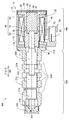
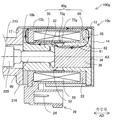
도 2는 솔레노이드의 상세 구성을 도시한 단면도이고,
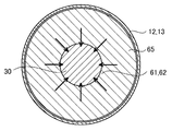
도 3은 도 2의 Ⅲ―Ⅲ선을 따른 단면을 도시한 단면도이고,
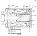
도 4는 비교예의 솔레노이드를 도시한 단면도이고,
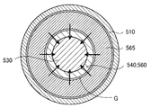
도 5는 도 4의 Ⅴ―Ⅴ선을 따른 단면을 도시한 단면도이고,
도 6은 링 코어가 편심하여 조립된 상태를 도시한 단면도이고,
도 7은 제 2 실시 형태의 솔레노이드의 상세 구성을 도시한 단면도이고,
도 8은 제 3 실시 형태의 솔레노이드의 상세 구성을 도시한 단면도이고,
도 9는 제 4 실시 형태의 솔레노이드의 상세 구성을 도시한 단면도이고,
도 10은 제 5 실시 형태의 솔레노이드의 상세 구성을 도시한 단면도이고,
도 11은 제 6 실시 형태의 솔레노이드의 상세 구성을 도시한 단면도이고,
도 12는 제 7 실시 형태의 솔레노이드의 상세 구성을 도시한 단면도이고,
도 13은 제 8 실시 형태의 솔레노이드의 상세 구성을 도시한 단면도이고,
도 14는 제 9 실시 형태의 솔레노이드의 상세 구성을 도시한 단면도이다.The said objective about this indication, the other objective, the characteristic, and an advantage become clearer by the following detailed description, referring an accompanying drawing. That drawing is
1 is a cross-sectional view showing a schematic configuration of a linear solenoid valve to which a solenoid of a first embodiment is applied;
2 is a cross-sectional view showing the detailed configuration of the solenoid,
3 is a cross-sectional view showing a cross-section taken along line III-III of FIG.
4 is a cross-sectional view showing a solenoid of a comparative example,
5 is a cross-sectional view showing a cross-section taken along the line V - V of FIG. 4,
6 is a cross-sectional view showing a state in which the ring core is eccentrically assembled;
7 is a cross-sectional view showing the detailed configuration of the solenoid of the second embodiment;
8 is a cross-sectional view showing the detailed configuration of the solenoid according to the third embodiment;
9 is a cross-sectional view showing the detailed configuration of the solenoid according to the fourth embodiment;
10 is a cross-sectional view showing a detailed configuration of a solenoid according to the fifth embodiment;
11 is a cross-sectional view showing a detailed configuration of a solenoid according to the sixth embodiment;
12 is a cross-sectional view showing a detailed configuration of a solenoid according to the seventh embodiment;
13 is a cross-sectional view showing a detailed configuration of a solenoid according to an eighth embodiment;
14 is a cross-sectional view showing a detailed configuration of a solenoid according to a ninth embodiment.
A. 제 1 실시 형태A. First embodiment
A―1. 구성A-1. Configuration
도 1에 도시한 제 1 실시 형태의 솔레노이드(100)는 리니어 솔레노이드 밸브(300)에 적용되고, 스풀 밸브(200)를 구동시키는 액추에이터로서 기능한다. 리니어 솔레노이드 밸브(300)는 도시하지 않는 차량용 자동 변속기에 공급하는 작동유의 유압을 제어하기 위해 이용되고, 도시하지 않는 유압 회로에 배치되어 있다. 리니어 솔레노이드 밸브(300)는 중심축(AX)을 따라서 서로 나란히 배치된 스풀 밸브(200)와 솔레노이드(100)를 구비한다. 또한, 도 1 및 도 2에서는 비통전 상태의 솔레노이드(100) 및 리니어 솔레노이드 밸브(300)를 도시하고 있다. 본 실시 형태의 리니어 솔레노이드 밸브(300)는 노멀리 클로즈 타입이지만, 노멀리 오픈 타입이어도 좋다.The
도 1에 도시한 스풀 밸브(200)는 후술하는 복수의 오일 포트(214)의 연통 상태 및 개구 면적을 조정한다. 스풀 밸브(200)는 슬리브(210)와, 스풀(220)과, 스프링(230)과, 조정 스크류(240)를 구비한다.The
슬리브(210)는 대략 원통 형상의 외관 형상을 가진다. 슬리브(210)에는 중심축(AX)을 따라서 관통하는 삽입 구멍(212)과, 삽입 구멍(212)과 연통하여 직경 방향으로 개구하는 복수의 오일 포트(214)가 형성되어 있다. 삽입 구멍(212)에는 스풀(220)이 삽입되어 있다. 복수의 오일 포트(214)는 중심축(AC)과 평행한 방향(이하, “축방향(AD)”이라고도 부른다)을 따라서 서로 나란히 형성되어 있다. 복수의 오일 포트(214)에는 예를 들면, 도시하지 않는 오일 펌프와 연통하여 유압의 공급을 받는 입력 포트, 도시하지 않는 클러치 피스톤 등과 연통하여 유압을 공급하는 출력 포트, 작동유를 배출하는 드레인 포트 등이 해당된다. 슬리브(210)의 솔레노이드(100)측의 단부에는 차양부(216)가 형성되어 있다. 차양부(216)는 직경 방향 외측을 향하여 직경이 확대되어 있고, 후술하는 솔레노이드(100)의 요크(10)와 서로 고정된다.The
스풀(220)은 축방향(AD)을 따라서 복수의 대직경부(222)와 소직경부(224)가 나란히 배치된 대략 막대 형상의 외관 형상을 가진다. 스풀(220)은 삽입 구멍(212)의 내부에서 축방향(AD)을 따라서 슬라이딩하고, 대직경부(222)와 소직경부(224)의 축방향(AD)을 따르는 위치에 따라서 복수의 오일 포트(214)의 연통 상태 및 개구 면적을 조정한다. 스풀(220)의 일단에는 솔레노이드(100)의 추력(推力)을 스풀(220)에 전달하기 위한 샤프트(90)가 맞닿아서 배치되어 있다. 스풀(220)의 타단에는 스프링(230)이 배치되어 있다. 스프링(230)은 압축 코일 스프링에 의해 구성되고, 스풀(220)을 축방향(AD)으로 눌러서 솔레노이드(100)측으로 가압한다. 조정 스크류(240)는 스프링(230)과 맞닿아서 배치되고, 슬리브(210)에 대한 나사 조임량이 조정됨으로써 스프링(230)의 스프링 하중을 조정한다.The
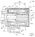
도 1 및 도 2에 도시한 솔레노이드(100)는 도시하지 않는 전자 제어 장치에 의하여 통전 제어되어, 스풀 밸브(200)를 구동한다. 솔레노이드(100)는 요크(10)와, 저부(14)와, 코일(20)과, 플런저(30)와, 스테이터 코어(40)를 구비한다.The
도 2에 도시한 바와 같이, 요크(10)는 자성체의 금속에 의해 형성되고, 솔레노이드(100)의 외곽을 구성하고 있다. 요크(10)는 축방향(AD)을 따르는 대략 원통 형상의 외관 형상을 가지고, 코일(20)과 플런저(30)와 스테이터 코어(40)를 수용한다. 요크(10)는 통부(12)와, 개구부(17)와, 벽부(18)를 가진다.As shown in FIG. 2 , the
통부(12)는 축방향(AD)을 따르는 대략 원통 형상의 외관 형상을 가진다. 통부(12)의 스풀 밸브(200)측과는 반대측의 단부는 얇은 두께로 형성되어, 박육부(13)를 구성하고 있다. 개구부(17)는 통부(12)의 스풀 밸브(200)측의 단부에 형성되어 있다. 개구부(17)는 요크(10)의 내부에 솔레노이드(100)의 구성 부품이 조립된 후, 스풀 밸브(200)의 차양부(216)와 코킹 고정된다. 벽부(18)는 축방향(AD)에서 코일(20)과 스풀 밸브(200)의 차양부(216) 사이에 위치하도록 통부(12)로부터 직경 방향 내측을 향하여 형성되어 있다. 벽부(18)는 스테이터 코어(40)와 요크(10)의 통부(12) 사이에서 자속을 주고받는다. 벽부(18)와 스테이터 코어(40) 사이에는 직경 방향에서 미소한 간극이 설치되어 있다. 이러한 간극에 의해 스테이터 코어(40)의 제조상의 치수 불균일과 조립상의 축 어긋남이 흡수되어, 조립상의 결함의 발생이 억제된다.The
저부(14)는 원판 형상의 외관 형상을 가지고, 요크(10)의 스풀 밸브(200)측과는 반대측의 단부에서 축방향(AD)과 수직으로 배치되어, 통부(12)의 단부를 폐색하고 있다. 또한, 저부(14)는 축방향(AD)과 수직에 한정되지 않고, 대략 수직으로 배치되어도 좋고, 축방향(AD)과 교차하여 배치되어도 좋다. 저부(14)는 후술하는 플런저(30)의 기단면(34)과 대향해 있다. 저부(14)는 통부(12)에 형성된 박육부(13)와 코킹 고정된다.The
코일(20)은 요크(10)의 통부(12)의 내측에 배치된 수지제의 보빈(22)에 절연 피복이 실시된 도선이 감겨서 구성되어 있다. 코일(20)을 구성하는 도선의 단부는 접속 단자(24)에 접속되어 있다. 접속 단자(24)는 커넥터(26)의 내부에 배치되어 있다. 커넥터(26)는 요크(10)의 외주부에 배치되고, 도시하지 않는 접속선을 통하여 솔레노이드(100)와 전자 제어 장치의 전기적인 접속을 실시한다. 코일(20)은 통전됨으로써 자력을 발생하고, 요크(10)의 통부(12)와, 스테이터 코어(40)와, 플런저(30)를 지나는 루프 형상의 자속의 흐름(이하, “자기 회로”라고도 부른다)을 형성시킨다. 도 1 및 도 2에 도시한 상태에서는 코일(20)로의 통전이 실행되지 않아서, 자기 회로가 형성되어 있지 않지만, 설명의 편의상, 코일(20)로의 통전이 실행된 경우에 형성되는 자기 회로(C1)를 도 2에 도시하고 있다.The
플런저(30)는 대략 원기둥 형상의 외관 형상을 가지고, 자성체의 금속에 의해 구성되어 있다. 플런저(30)는 후술하는 스테이터 코어(40)의 코어부(61)의 직경 방향 내측에서 축방향(AD)으로 슬라이딩한다. 플런저(30)의 스풀 밸브(200)측의 단면(이하, “선단면(32)”이라고도 부른다)에는 상기한 샤프트(90)가 맞닿아서 배치되어 있다. 이에 따라, 플런저(30)는 스풀(220)에 전달되는 스프링(230)의 가압력에 의해 축방향(AD)을 따라서 저부(14)측으로 가압된다. 선단면(32)과는 반대측의 단면(이하, “기단면(34)”이라고도 부른다)은 저부(14)와 대향해 있다. 플런저(30)에는 축방향(AD)으로 관통하는 도시하지 않는 호흡 구멍이 형성되어 있다. 이러한 호흡 구멍은 예를 들면, 작동유나 공기 등의, 플런저(30)의 기단면(34)측 및 선단면(32)측에 위치하는 유체를 통과시킨다.The
스테이터 코어(40)는 자성체의 금속에 의해 구성되고, 코일(20)과 플런저(30) 사이에 배치되어 있다. 스테이터 코어(40)는 자기 흡인 코어(50)와, 슬라이딩 코어(60)와, 자속 통과 억제부(70)를 가진다.The
자기 흡인 코어(50)는 샤프트(90)를 원주 방향으로 둘러싸서 배치되어 있다. 자기 흡인 코어(50)는 스테이터 코어(40) 중, 스풀 밸브(200)측의 일부를 구성하고, 코일(20)이 발생하는 자력에 의해 플런저(30)를 자기 흡인한다. 자기 흡인 코어(50)의, 플런저(30)의 선단면(32)과 대향하는 면에는 스토퍼(52)가 배치되어 있다. 스토퍼(52)는 비자성체에 의해 구성되어, 플런저(30)와 자기 흡인 코어(50)가 직접 맞닿는 것을 억제하고, 자기 흡인에 의해 자기 흡인 코어(50)로부터 플런저(30)가 이격되지 않게 되는 것을 억제한다.The
슬라이딩 코어(60)는 스테이터 코어(40) 중, 저부(14)측의 일부를 구성하고, 플런저(30)의 직경 방향 외측에 배치되어 있다. 슬라이딩 코어(60)는 코어부(61)와, 자속 전달부(65)를 가진다.The sliding
코어부(61)는 대략 원통 형상의 외관 형상을 가지고, 직경 방향에서 코일(20)과 플런저(30) 사이에 배치되어 있다. 코어부(61)는 플런저(30)의 축방향(AD)을 따르는 이동을 가이드한다. 이에 따라, 플런저(30)는 코어부(61)의 내주면을 직접 슬라이딩한다. 코어부(61)와 플런저(30) 사이에는 플런저(30)의 슬라이딩성을 확보하기 위한 도시하지 않는 슬라이딩 갭이 존재하고 있다. 슬라이딩 코어(60)의 단부로서, 자기 흡인 코어(50)측과는 반대측의 단부(이하, “단부(62)”라고도 부른다)는 저부(14)와 대향하여 맞닿아 있다.The
자속 전달부(65)는 단부(62)의 전체 둘레에 걸쳐서 단부(62)로부터 직경 방향 외측을 향하여 형성되어 있다. 이 때문에, 자속 전달부(65)는 축방향(AD)에서 보빈(22)과 저부(14) 사이에 위치해 있다. 자속 전달부(65)는 코어부(61)를 통하여 요크(10)와 플런저(30) 사이에서 자속을 주고받는다. 보다 구체적으로는, 요크(10)의 통부(12)로부터 전달되는 자속을 플런저(30)로 전달한다. 또한, 자속 전달부(65)는 저부(14)로부터 전달되는 자속을 플런저(30)로 전달해도 좋다.The magnetic
본 실시 형태에 있어서, 자속 전달부(65)는 통부(12)의 박육부(13)의 내주측에 수용되어 있다. 자속 전달부(65)의 외주면과 박육부(13)의 내주면 사이에는 조립을 위한 미소한 간극이 설치되어 있다. 자속 전달부(65)는 축방향(AD)에 있어서, 보빈(22) 및 저부(14)와 각각 서로 맞닿아 있다.In this embodiment, the magnetic
자속 통과 억제부(70)는 축방향(AD)에 있어서, 자기 흡인 코어(50)와 코어부(61) 사이에 형성되어 있다. 자속 통과 억제부(70)는 코어부(61)와 자기 흡인 코어(50) 사이에서 직접적으로 자속이 흐르는 것을 억제한다. 본 실시 형태의 자속 통과 억제부(70)는 스테이터 코어(40)의 직경 방향의 두께가 얇은 두께로 형성됨으로써 자기 흡인 코어(50) 및 코어부(61)보다도 자기 저항이 커지도록 구성되어 있다.The magnetic flux
본 실시 형태에 있어서, 요크(10)와, 저부(14)와, 플런저(30)와, 스테이터 코어(40)는 각각 철에 의해 구성되어 있다. 또한, 철에 한정되지 않고, 니켈이나 코발트 등, 임의의 자성체에 의해 구성되어도 좋다. 또한, 본 실시 형태에 있어서, 스테이터 코어(40)는 단조에 의해 형성되어 있지만, 다른 임의의 성형 방법에 의해 형성되어도 좋다.In this embodiment, the
도 2에서는 설명의 편의상, 통전에 의해 형성되는 자기 회로를 굵은 선의 화살표로 모식적으로 도시하고 있다. 자기 회로는 요크(10)의 통부(12)와, 스테이터 코어(40)의 자속 전달부(65)와, 스테이터 코어(40)의 코어부(61)와, 플런저(30)와, 스테이터 코어(40)의 자기 흡인 코어(50)와, 요크(10)의 벽부(18)를 지나도록 형성된다. 이 때문에, 코일(20)로의 통전에 의하여 플런저(30)가 자기 흡인 코어(50)측으로 끌어당겨진다. 이에 따라, 플런저(30)는 코어부(61)의 직경 방향 내측, 바꾸어 말하면, 슬라이딩 코어(60)의 직경 방향 내측에 있어서, 축방향(AD)을 따라서 백색 화살표 방향으로 슬라이딩한다. 이와 같이, 플런저(30)는 코일(20)로의 통전에 의하여 스프링(230)의 가압력에 대항해서 자기 흡인 코어(50)측으로 스트로크한다. 코일(20)에 흐르는 전류가 클수록 자기 회로의 자속 밀도가 증가하여, 플런저(30)의 스트로크량이 증가한다. “플런저(30)의 스트로크량”이란, 플런저(30)의 왕복 운동에 있어서, 플런저(30)가 자기 흡인 코어(50)로부터 가장 멀어진 위치를 기점으로 하여, 플런저(30)가 자기 흡인 코어(50)측으로 축방향(AD)을 따라서 이동하는 양을 의미한다. 플런저(30)가 자기 흡인 코어(50)로부터 가장 멀어진 상태는 비통전 상태에 상당한다. 한편, 도 2와는 달리, 플런저(30)가 자기 흡인 코어(50)에 가장 가까워진 상태는, 코일(20)에 통전이 실시되어, 플런저(30)의 선단면(32)과 스토퍼(52)가 맞닿은 상태에 상당하고, 플런저(30)의 스트로크량이 최대로 된다.In Fig. 2, for convenience of explanation, a magnetic circuit formed by energization is schematically shown by a thick-lined arrow. The magnetic circuit includes a
플런저(30)의 선단면(32)에 맞닿는 샤프트(90)는 플런저(30)가 자기 흡인 코어(50)측으로 스트로크하면, 도 1에 도시한 스풀(220)을 스프링(230)측으로 누른다. 이에 따라, 오일 포트(214)의 연통 상태 및 개구 면적이 조정되어, 코일(20)에 흐르는 전류값에 비례한 유압이 출력된다.When the
도 3에 도시한 바와 같이, 본 실시 형태의 슬라이딩 코어(60)는 코어부(61)와 자속 전달부(65)가 일체로 형성되어 있다. 이 때문에, 코어부(61)와 자속 전달부(65) 사이에 직경 방향의 간극이 존재하지 않는다. 따라서, 통전에 의해 자기 회로가 구성된 경우에, 자속 전달부(65)로부터 코어부(61)로 전달되는 자속의 분포에 직경 방향의 편향이 발생하는 것을 억제할 수 있어서, 코어부(61)로부터 플런저(30)로 전달되는 자속의 분포에 직경 방향의 편향이 발생하는 것을 억제할 수 있다. 바꾸어 말하면, 도 3에서 화살표로 도시한 바와 같이, 자기 회로의 자속 밀도는 원주 방향에서 대략 동등하다. 이 때문에, 자속의 분포의 편향에 의한 사이드 포스의 발생을 억제할 수 있다.As shown in FIG. 3, in the sliding
A―2. 비교예A-2. Comparative example
도 4 및 도 5에 도시한 비교예의 솔레노이드(500)에서는 대략 원통 형상으로 형성된 스테이터 코어(540)의 슬라이딩 코어(560)에 대하여 직경 방향 외측에 자성체의 링 코어(565)가 배치되어 있다. 링 코어(565)는 요크(510)와 플런저(530) 사이에서 자속을 주고받는다. 또한, 도 4에 도시한 바와 같이, 스테이터 코어(540)의 자기 흡인 코어(550)에서의 축방향(AD)의 단부로서, 플런저(530)측과는 반대측의 단부에는 직경 방향 외측으로 돌출하는 플랜지부(558)가 형성되어 있다. 플랜지부(558)는 요크(510)의 통부(512)와의 사이에서 자속을 주고받는다. 비교예의 솔레노이드(500)에서는 코일(20)과 스풀 밸브(200)의 차양부(216) 사이에 플랜지부(558)가 끼워진 상태로 차양부(216)와 통부(512)가 코킹 고정됨으로써 스테이터 코어(540)가 요크(510)에 대하여 고정된다. 도 4 및 도 5에 도시한 바와 같이, 비교예의 솔레노이드(500)에서는 슬라이딩 코어(560)와 링 코어(565) 사이에 직경 방향의 간극(G)이 존재하고 있다. 이와 같은 구성에 의하여, 링 코어(565)는 직경 방향으로 이동 가능하게 구성되고, 스테이터 코어(540)의 제조상의 치수 불균일과 조립상의 축 어긋남에 기인하는 슬라이딩 코어(560)의 단부(562)의 직경 방향의 변위를 흡수하고 있다.In the
도 6에서는 도 5와 동일한 단면에 있어서, 슬라이딩 코어(560)에 대하여 링 코어(565)가 가장 편심해서 조립된 상태를 도시하고 있다. 슬라이딩 코어(560)에 대하여 링 코어(565)가 편심해서 조립되면, 슬라이딩 코어(560)와 링 코어(565) 사이의 간극(G)의 크기에 직경 방향의 편향이 발생할 염려가 있다. 일반적으로, 통전에 의해 발생하는 자속은 자기 저항이 큰 영역보다도 자기 저항이 작은 영역에서 우선하여 전달된다. 이 때문에, 도 6에 도시한 상태에서는 슬라이딩 코어(560)와 링 코어(565) 사이의 직경 방향의 간극(G)이 작은 영역에서 굵은 선의 화살표로 도시한 바와 같이 자속 밀도가 증가한다. 한편, 슬라이딩 코어(560)와 링 코어(565) 사이의 직경 방향의 간극(G)이 큰 영역에서 가는 선의 화살표로 도시한 바와 같이 자속 밀도가 감소한다. 이에 따라, 링 코어(565)를 지나서 슬라이딩 코어(560)와 플런저(530)로 전달되는 자속의 분포에 직경 방향의 편향이 발생하고, 도 6에서 백색 화살표로 도시한 바와 같이, 직경 방향으로의 흡인력이 사이드 포스로서 발생할 염려가 있다. 사이드 포스가 커지면, 플런저(530)의 슬라이딩성이 악화할 염려가 있다.In FIG. 6 , in the same cross section as FIG. 5 , the
이에 대해, 본 실시 형태의 솔레노이드(100)에서는 코어부(61)와 자속 전달부(65) 사이에 직경 방향의 간극이 존재하지 않는다. 이 때문에, 코어부(61)를 통하여 자속 전달부(65)로부터 플런저(30)로 전달되는 자속의 분포에 직경 방향의 편향이 발생하는 것을 억제할 수 있어서, 자속의 분포의 편향에 의한 사이드 포스의 발생을 억제할 수 있다. 또한, 본 실시 형태의 솔레노이드(100)의 스테이터 코어(40)는 비교예의 솔레노이드(500)와는 달리, 플랜지부(558)가 생략되고, 요크(10)는 통부(12)로부터 직경 방향 내측을 향하여 형성된 벽부(18)를 가진다. 이 때문에, 벽부(18)와 스테이터 코어(40) 사이에는 상기와 같이, 솔레노이드(100)의 조립상 필요한 직경 방향의 미소한 간극이 설치되어 있다.In contrast, in the
이상 설명한 제 1 실시 형태의 솔레노이드(100)에 따르면, 슬라이딩 코어(60)가 플런저(30)의 직경 방향 외측에 배치된 통형상의 코어부(61)와, 코어부(61)의 단부(62)로부터 직경 방향 외측을 향하여 형성되어 자속을 주고받는 자속 전달부(65)를 가지기 때문에 코어부(61)와 자속 전달부(65) 사이에 직경 방향의 간극이 존재하지 않는다. 이 때문에, 코어부(61)를 통하여 자속 전달부(65)로부터 플런저(30)로 전달되는 자속의 분포에 직경 방향의 편향이 발생하는 것을 억제할 수 있어서, 자속의 분포의 편향에 의한 사이드 포스의 발생을 억제할 수 있다. 따라서, 플런저(30)의 슬라이딩성의 악화를 억제할 수 있다.According to the
또한, 코어부(61)의 단부(62)의 주변에 있어서, 슬라이딩 갭 이외에 직경 방향의 간극이 존재하지 않기 때문에 자기 효율의 저하를 억제할 수 있다. 또한, 스테이터 코어(40)가, 자기 흡인 코어(50)와 슬라이딩 코어(60)와 자속 통과 억제부(70)가 일체화된 단일한 부재에 의해 구성되어 있기 때문에 부품수의 증가를 억제할 수 있다.Further, in the periphery of the
B. 제 2 실시 형태:B. Second embodiment:
도 7에 도시한 제 2 실시 형태의 솔레노이드(100a)는 스테이터 코어(40)에 대신하여 스테이터 코어(40a)를 구비하는 점에 있어서 제 1 실시 형태의 솔레노이드(100)와 다르다. 그 밖의 구성은 제 1 실시 형태의 솔레노이드(100)와 같기 때문에 동일한 구성에는 동일한 부호를 붙이고, 그들의 상세한 설명을 생략한다. 또한, 도 7에 도시한 상태에서는 코일(20)로의 통전이 실행되지 않아서, 자기 회로가 형성되어 있지 않지만, 참고를 위해, 코일(20)로의 통전이 실행된 경우에 형성되는 자기 회로를 도시하고 있다. 후술하는 도 8 내지 도 13에서도 마찬가지로, 자기 회로를 도시하고 있다.The
제 2 실시 형태의 솔레노이드(100a)가 구비하는 스테이터 코어(40a)의 슬라이딩 코어(60a)는 코어부(61a)와 자속 전달부(65a)가 별개체로 형성되어 있다. 자속 전달부(65a)는 링형상의 외관 형상을 가진다. 이 때문에, 자속 전달부(65a)에는 직경 방향 내측에서 축방향(AD)으로 관통하는 관통 구멍(66a)이 형성되어 있다. 관통 구멍(65a)에는 코어부(61a)의 단부(62a)가 압입되어 있다. 이러한 압입에 의해 코어부(61a)와 자속 전달부(65a)가 일체 구조로 되도록 조립된다. 따라서, 코어부(61a)와 자속 전달부(65a) 사이에는 직경 방향의 간극이 대략 존재하지 않는다. 또한, 압입에 한정되지 않고, 코어부(61a)가 관통 구멍(66a)에 삽입되어 용접 등에 의해 자속 전달부(65a)와 일체화되어 있어도 좋다.As for the sliding
이상 설명한 제 2 실시 형태의 솔레노이드(100a)에 따르면, 제 1 실시 형태와 동일한 효과를 이룬다. 또한, 자속 전달부(65a)가 코어부(61a)와 별개체로 형성되어 관통 구멍(66a)을 가지고, 코어부(61a)가 관통 구멍(66a)에 삽입되어 자속 전달부(65a)와 일체화되어 있기 때문에 스테이터 코어(40a)의 구조의 복잡화를 억제할 수 있어서, 스테이터 코어(40a)의 제조에 요하는 비용이 증가하는 것을 억제할 수 있다.According to the
C. 제 3 실시 형태:C. Third embodiment:
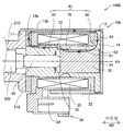
도 8에 도시한 제 3 실시 형태의 솔레노이드(100b)는 요크(10)에 대신하여 요크(10b)를 구비하고, 링 부재(18b)를 더 구비하는 점에 있어서 제 1 실시 형태의 솔레노이드(100)와 다르다. 그 밖의 구성은 제 1 실시 형태의 솔레노이드(100)와 같기 때문에 동일한 구성에는 동일한 부호를 붙이고, 그들의 상세한 설명을 생략한다.The
제 3 실시 형태의 솔레노이드(100b)가 구비하는 요크(10b)는 통부(12b)에서 벽부(18)가 생략되어 있다. 또한, 제 3 실시 형태의 솔레노이드(100b)에서는 벽부(18)가 생략된 위치에 링 부재(18b)가 배치되어 있다. 바꾸어 말하면, 링 부재(18b)는 자기 흡인 코어(50)에서의 축방향(AD)의 단부로서, 플런저(30)측과는 반대측의 단부의 직경 방향 외측에 배치되어 있다. 링 부재(18b)는 링형상의 외관 형상을 가지고, 자성체의 금속에 의해 구성되어 있다. 링 부재(18b)는 스테이터 코어(40)의 자기 흡인 코어(50)와 요크(10b)의 통부(12b) 사이에서 자속을 주고받는다. 링 부재(18b)는 통부(12b)와 고정되어 있지 않기 때문에 직경 방향에서 변위 가능하게 구성되어 있다.As for the
이상 설명한 제 3 실시 형태의 솔레노이드(100b)에 따르면, 제 1 실시 형태와 동일한 효과를 이룬다. 또한, 벽부(18)가 생략된 위치에 링형상의 링 부재(18b)가 배치되어 있기 때문에 스테이터 코어(40)의 제조상의 치수 불균일과 조립상의 축 어긋남을 흡수할 수 있다. 또한, 링 부재(18b)가 요크(10b)의 통부(12b)와 고정되어 있지 않기 때문에 통부(12b)와 스테이터 코어(40)의 조립상의 축 어긋남을 흡수하기 위해, 스테이터 코어(40)의 직경 방향 외측에 과도하게 큰 간극을 설치하는 것을 억제할 수 있다. 이 때문에, 링 부재(18b)와 스테이터 코어(40) 사이에서의 직경 방향의 간극의 크기를 작게 할 수 있기 때문에 자기 효율의 저하를 억제할 수 있다, 또한, 벽부(18)가 생략되어 있기 때문에 요크(10b)의 구조의 복잡화를 억제할 수 있어서, 요크(10b)의 제조에 요하는 비용이 증가하는 것을 억제할 수 있다.According to the
D. 제 4 실시 형태:D. Fourth embodiment:
도 9에 도시한 제 4 실시 형태의 솔레노이드(100c)는 스테이터 코어(40)에 대신하여 제 2 실시 형태의 스테이터 코어(40a)를 구비하는 점에 있어서 제 3 실시 형태의 솔레노이드(100b)와 다르다. 그 밖의 구성은 제 3 실시 형태의 솔레노이드(100b)와 같기 때문에 동일한 구성에는 동일한 부호를 붙이고, 그들의 상세한 설명을 생략한다.The
제 4 실시 형태의 솔레노이드(100c)는 제 2 실시 형태의 솔레노이드(100a)와 제 3 실시 형태의 솔레노이드(100b)를 조합한 구성을 가진다. 즉, 스테이터 코어(40a)의 축방향(AD)의 단부로서, 저부(14)측의 단부(62a)는 자속 전달부(65a)의 관통 구멍(66a)에 압입되고, 스테이터 코어(40a)의 축방향(AD)의 단부로서, 스풀 밸브(200)측의 단부의 직경 방향 외측에는 링 부재(18b)가 배치되어 있다.The
이상 설명한 제 4 실시 형태의 솔레노이드(100c)에 따르면, 제 2 실시 형태 및 제 3 실시 형태와 동일한 효과를 이룬다. 또한, 스테이터 코어(40a)의 축방향(AD)의 양단부에 있어서, 직경 방향의 간극을 생략 또는 간극의 크기를 작게 할 수 있기 때문에 자기 효율의 저하를 보다 억제할 수 있다.According to the
E. 제 5 실시 형태:E. Fifth embodiment:
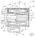
도 10에 도시한 제 5 실시 형태의 솔레노이드(100d)는 요크(10d)가 통부(12b)에 대신하여 통부(12d)를 구비하는 점에 있어서 제 3 실시 형태의 솔레노이드(100b)와 다르다. 그 밖의 구성은 제 3 실시 형태의 솔레노이드(100b)와 같기 때문에 동일한 구성에는 동일한 부호를 붙이고, 그들의 상세한 설명을 생략한다.The
제 5 실시 형태의 솔레노이드(100d)가 구비하는 통부(12d)에는, 축방향(AD)에서 자속 전달부(65)와 코일(20) 사이에 직경 방향 내측을 향하여 자속 통과 면적 확대부(19d)가 형성되어 있다. 자속 통과 면적 확대부(19d)는 자속 전달부(65) 및 코일(20)과 각각 서로 맞닿아 있다. 자속 통과 면적 확대부(19d)는 통부(12d)로부터 자속 전달부(65)로 전달되는 자속의 통과 면적으로서, 미리 정해진 한계값 면적 이상의 면적을 확보한다. 한계값 면적은 이러한 자속의 통과 면적이 과도하게 작은 것에 기인하여 솔레노이드(100d)의 자기 효율이 저하하는 것을 억제할 수 있는 면적으로 설정되어 있다. 도 10에서 루프 형상의 화살표로 도시한 바와 같이, 솔레노이드(100d)가 통전되면, 통부(12d)와, 자속 통과 면적 확대부(19d)와, 자속 전달부(65)와, 코어부(61)로 순서대로 전달되는 자기 회로가 형성된다.In the
이상 설명한 제 5 실시 형태의 솔레노이드(100d)에 따르면, 제 3 실시 형태와 동일한 효과를 이룬다. 또한, 통부(12d)로부터 자속 전달부(65)로 전달되는 자속의 통과 면적으로서, 미리 정해진 한계값 면적 이상의 면적을 확보하는 자속 통과 면적 확대부(19d)가 통부(12d)에 형성되어 있기 때문에 통부(12d)와 자속 전달부(65) 사이에서의 자속 통과 면적의 부족을 억제할 수 있다. 이 때문에, 스테이터 코어(40)의 제조상의 치수 불균일과 조립상의 축 어긋남에 기인하여, 통부(12d)와 자속 전달부(65) 사이에서 직경 방향의 위치 어긋남이 발생한 경우에 있어서도, 통부(12d)로부터 자속 전달부(65)로 전달되는 자속의 통과 면적이 부족한 것을 억제할 수 있다.According to the
F. 제 6 실시 형태:F. Sixth embodiment:
도 11에 도시한 제 6 실시 형태의 솔레노이드(100e)는 스테이터 코어(40)에 대신하여 제 2 실시 형태의 스테이터 코어(40a)를 구비하는 점에 있어서 제 5 실시 형태의 솔레노이드(100d)와 다르다. 그 밖의 구성은 제 5 실시 형태의 솔레노이드(100d)와 같기 때문에 동일한 구성에는 동일한 부호를 붙이고, 그들의 상세한 설명을 생략한다.The
제 6 실시 형태의 솔레노이드(100e)는 제 2 실시 형태의 솔레노이드(100a)와 제 5 실시 형태의 솔레노이드(100d)를 조합한 구성을 가진다.The
이상 설명한 제 6 실시 형태의 솔레노이드(100e)에 따르면, 제 2 실시 형태 및 제 5 실시 형태와 동일한 효과를 이룬다.According to the
G. 제 7 실시 형태:G. Seventh embodiment:
도 12에 도시한 제 7 실시 형태의 솔레노이드(100f)는 박육부(13)의 축방향(AD)의 길이가 약간 짧은 점과, 스테이터 코어(40)가 요크(10)의 통부(12)에 압입되어 있는 점에 있어서 제 3 실시 형태의 솔레노이드(100b)와 다르다. 그 밖의 구성은 제 3 실시 형태의 솔레노이드(100b)와 같기 때문에 동일한 구성에는 동일한 부호를 붙이고, 그들의 상세한 설명을 생략한다.In the
제 7 실시 형태의 솔레노이드(100f)가 구비하는 스테이터 코어(40)는 통부(12)의 박육부(13)측의 단부에 압입되어 있다. 이러한 압입에 의해 통부(12)의 내주면과 자속 전달부(65)의 외주면 사이에는 직경 방향의 간극이 대략 존재하지 않는다.The
이상 설명한 제 7 실시 형태의 솔레노이드(100f)에 따르면, 제 3 실시 형태와 동일한 효과를 이룬다. 또한, 통부(12)의 내주면과 자속 전달부(65)의 외주면 사이에서 직경 방향의 간극을 생략할 수 있기 때문에 자기 효율의 저하를 억제할 수 있다. 또한, 통부(12)로부터 자속 전달부(65)로 전달되는 자속의 통과 면적으로서, 미리 정해진 한계값 면적 이상의 면적을 용이하게 확보할 수 있다.According to the
H. 제 8 실시 형태:H. Eighth embodiment:
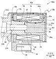
도 13에 도시한 제 8 실시 형태의 솔레노이드(100g)는 자속 통과 억제부(70)에 대신하여 자속 통과 억제부(70g)를 가지는 스테이터 코어(40g)를 구비하는 점에 있어서 제 3 실시 형태의 솔레노이드(100b)와 다르다. 그 밖의 구성은 제 3 실시 형태의 솔레노이드(100b)와 같기 때문에 동일한 구성에는 동일한 부호를 붙이고, 그들의 상세한 설명을 생략한다.The
제 8 실시 형태의 솔레노이드(100g)에서의 자속 통과 억제부(70g)는 비자성체에 의해 형성된 접속부(72g)를 포함한다. 접속부(72g)는 분리하여 형성된 자기 흡인 코어(50)와 슬라이딩 코어(60)를 물리적으로 접속하고 있다. 본 실시 형태에 있어서, 접속부(72g)는 코어부(61)보다도 얇은 두께로 형성되고, 코일(20)의 내주면측에서 자기 흡인 코어(50)와 슬라이딩 코어(60)를 물리적으로 접속하고 있다. 이 때문에, 접속부(72g)의 내주면과 플런저(30)의 외주면 사이에는 간극이 존재하고 있다. 또한, 본 실시 형태에 있어서, 접속부(72g)는 오스테나이트계 스테인레스강에 의해 형성되어 있지만, 오스테나이트계 스테인레스강에 한정되지 않고, 알루미늄이나 황동 등의 임의의 비자성체에 의해 형성되어 있어도 좋다.The magnetic flux
이상 설명한 제 8 실시 형태의 솔레노이드(100g)에 따르면, 제 3 실시 형태와 동일한 효과를 이룬다. 또한, 자속 통과 억제부(70g)가 비자성체에 의해 형성된 접속부(72g)를 포함하기 때문에 통전 시에 플런저(30)를 지나지 않고 코어부(61)로부터 자기 흡인 코어(50)로 자속이 직접적으로 통과하는 것을 보다 억제할 수 있다.According to the
I. 제 9 실시 형태:I. Ninth embodiment:
도 14에 도시한 제 9 실시 형태의 솔레노이드(100h)는 접속부(72g)에 대신하여 접속부(72h)를 포함하는 자속 통과 억제부(70h)를 가지는 점에 있어서 제 8 실시 형태의 솔레노이드(100g)와 다르다. 그 밖의 구성은 제 8 실시 형태의 솔레노이드(100g)와 같기 때문에 동일한 구성에는 동일한 부호를 붙이고, 그들의 상세한 설명을 생략한다.The
제 9 실시 형태의 솔레노이드(100h)에서의 접속부(72h)는 코어부(61)와 대략 동등한 두께로 납땜 등에 의해 형성되어 있다.The connecting
이상 설명한 제 9 실시 형태의 솔레노이드(100h)에 따르면, 제 8 실시 형태와 동일한 효과를 이룬다. 또한, 접속부(72h)가 코어부(61)와 대략 동등한 두께로 형성되어 있기 때문에 자기 흡인 코어(50)와 코어부(61)를 보다 강고하게 접속할 수 있다. 또한, 접속부(72h)에 있어서도, 플런저(30)의 슬라이딩을 가이드할 수 있다.According to the
J. 다른 실시 형태:J. Another embodiment:
(1) 제 5 실시 형태 및 제 6 실시 형태에 있어서, 자속 통과 면적 확대부(19d)는 축방향(AD)에서 자속 전달부(65)와 코일(20) 사이에 통부(12d)로부터 직경 방향 내측을 향하여 형성되어 있었지만, 본 개시는 이에 한정되는 것은 아니다. 예를 들면, 제 7 실시 형태의 솔레노이드(100f)와 같이, 스테이터 코어(40)가 요크(10)의 통부(12)에 압입됨으로써 통부(12)로부터 자속 전달부(65)로 전달되는 자속의 통과 면적으로서, 미리 정해진 한계값 면적 이상의 면적을 확보하는 양태이어도 좋다. 이러한 양태에 있어서, 통부(12) 중, 자속 전달부(65)가 압입되는 부분은 본 개시에서의 자속 통과 면적 확대부에 상당한다. 즉, 일반적으로, 요크에는 요크로부터 자속 전달부로 전달되는 자속의 통과 면적으로서, 미리 정해진 한계값 면적 이상의 면적을 확보하는 자속 통과 면적 확대부가 형성되어 있어도 좋다. 이러한 구성에 의해서도 상기 각 실시 형태와 동일한 효과를 이룬다.(1) In the fifth and sixth embodiments, the magnetic flux passing area enlarged
(2) 상기 각 실시 형태의 솔레노이드(100, 100a∼100h)의 구성은 어디까지나 일례이고, 여러 가지로 변경 가능하다. 예를 들면, 상기 각 실시 형태에서는 저부(14)가 자성체의 금속에 의해 형성되어 있었지만, 자성체에 한정되지 않고, 알루미늄 등의 비자성체에 의해 형성되어 있어도 좋다. 이와 같은 구성에 따르면, 저부(14)가 플런저(30)를 흡인하는 힘의 발생을 억제할 수 있어서, 자기 효율의 저하를 더욱 억제할 수 있다. 또한, 유압 회로의 작동유에 포함되는 자성체의 이물이 저부(14)에 부착하는 것을 억제할 수 있다. 또한, 저부(14)는 코킹 고정에 한정되지 않고, 용접 등의 임의의 고정 방법에 의해 요크(10, 10b, 10d)와 고정되어 있어도 좋고, 자속 전달부(65, 65a)와의 사이에 축방향(AD)의 간극이 설치되어 요크(10, 10b, 10d)와 고정되어 있어도 좋다. 즉, 저부(14)와 자속 전달부(65, 65a)는 압접(pressure welding)되어 있지 않아도 좋다. 또한, 저부(14)는 요크(10, 10b, 10d)에 한정되지 않고, 자속 전달부(65, 65a)와 고정되어 있어도 좋다. 또한, 예를 들면, 플런저(30)는 대략 원기둥 형상에 한정되지 않고, 임의의 기둥 형상의 외관 형상을 가지고 있어도 좋다. 또한, 코어부(61, 61a) 및 요크(10, 10b, 10d)의 통부(12, 12b, 12d)는 대략 원통 형상에 한정되지 않고, 플런저(30)의 외관 형상에 따른 통형상의 외관 형상으로 설계되어도 좋다. 또한, 요크(10, 10b, 10d)는 대략 원통 형상의 외관 형상을 가지고 있었지만, 단면에서 보아 대략 사각형 등의 임의의 통형상의 외관 형상을 가지고 있어도 좋고, 통형상에 한정되지 않고, 코일(20)과 플런저(30)를 둘러싸는 판형상 등의 외관 형상을 가지고 있어도 좋다. 이와 같은 구성에 의해서도 상기 각 실시 형태와 동일한 효과를 이룬다.(2) The configuration of the
(3) 상기 각 실시 형태의 솔레노이드(100, 100a∼100h)는 차량용 자동 변속기에 공급하는 작동유의 유압을 제어하기 위한 리니어 솔레노이드 밸브(300)에 적용되고, 스풀 밸브(200)를 구동시키는 액추에이터로서 기능하고 있었지만, 본 개시는 이에 한정되는 것은 아니다. 예를 들면, 엔진의 흡기 밸브 또는 배기 밸브의 밸브 타이밍을 조정하는 밸브 타이밍 조정 장치의 전자 유로 전환 밸브 등, 임의의 솔레노이드 밸브에 적용되어도 좋다. 또한, 예를 들면, 스풀 밸브(200)에 대신하여 포핏(poppet) 밸브 등의 임의의 밸브를 구동시켜도 좋고, 밸브에 대신하여 스위치 등의 임의의 피구동체를 구동시켜도 좋다.(3) The
본 개시는 상기의 각 실시 형태에 한정되는 것은 아니고, 그 취지를 일탈하지 않는 범위에서 여러 가지 구성으로 실현할 수 있다. 예를 들면, 발명의 개요의 란에 기재한 형태 중의 기술적 특징에 대응하는 각 실시 형태 중의 기술적 특징은 상기 과제의 일부 또는 전부를 해결하기 위해, 또는 상기 효과의 일부 또는 전부를 달성하기 위해, 적절히 교체나 조합을 실시하는 것이 가능하다. 또한, 그 기술적 특징이 본 명세서 중에 필수인 것으로서 설명되어 있지 않으면, 적절히 삭제하는 것이 가능하다.This indication is not limited to each said embodiment, It can implement|achieve with various structures in the range which does not deviate from the meaning. For example, the technical features in each embodiment corresponding to the technical features in the forms described in the column of the summary of the invention are appropriately used to solve some or all of the above problems or to achieve some or all of the above effects. It is possible to carry out replacement or combination. In addition, unless the technical feature is described as essential in this specification, it is possible to delete suitably.
Claims (5)
통전에 의해 자력을 발생하는 코일(20)과,
상기 코일의 내측에 배치되어, 축방향(AD)으로 슬라이딩하는 기둥 형상의 플런저(30)와,
상기 코일과 상기 플런저를 수용하는, 상기 축방향을 따르는 요크(10, 10b, 10d)와,
상기 축방향과 교차하는 방향에 배치되어, 상기 플런저의 기단면(34)과 대향하는 저부(14)와,
스테이터 코어(40, 40a, 40g)를 구비하고,
상기 스테이터 코어는,
상기 축방향에서 상기 플런저의 선단면(32)과 대향하여 배치되어, 상기 코일이 발생하는 자력에 의해 상기 플런저를 자기 흡인하는 자기 흡인 코어(50)와,
상기 플런저의 직경 방향 외측에 배치된 통형상의 코어부(61, 61a)와, 상기 저부와 대향하는 상기 코어부의 단부(62, 62a)로부터 직경 방향 외측을 향하여 형성되어, 상기 코어부를 통해서 상기 요크와 상기 플런저 사이에서 자속을 주고받는 자속 전달부(65, 65a)를 가지는 슬라이딩 코어(60, 60a)와,
상기 슬라이딩 코어와 상기 자기 흡인 코어 사이에서의 자속의 통과를 억제하는 자속 통과 억제부(70, 70g, 70h)를 구비하는
솔레노이드.
As a solenoid (100, 100a to 100h),
A coil 20 that generates magnetic force by energization, and
a column-shaped plunger 30 disposed inside the coil and sliding in the axial direction (AD);
a yoke (10, 10b, 10d) along the axial direction for receiving the coil and the plunger;
a bottom portion (14) disposed in a direction crossing the axial direction and facing the proximal end surface (34) of the plunger;
Having a stator core (40, 40a, 40g),
The stator core is
a magnetic attraction core (50) disposed to face the front end surface (32) of the plunger in the axial direction and magnetically attracting the plunger by the magnetic force generated by the coil;
Cylindrical core portions 61 and 61a disposed on the radially outer side of the plunger, and end portions 62 and 62a of the core portion opposite to the bottom portion are formed radially outward, and the yoke is formed through the core portion and a sliding core (60, 60a) having a magnetic flux transmitting part (65, 65a) for exchanging magnetic flux between the plunger and;
and a magnetic flux passage restraining unit (70, 70g, 70h) for suppressing the passage of magnetic flux between the sliding core and the magnetic attraction core.
solenoid.
상기 자기 흡인 코어에서의 상기 축방향의 단부로서, 상기 플런저측과는 반대측의 단부의 직경 방향 외측에는 상기 요크와 상기 자기 흡인 코어 사이에서 자속을 주고받는 링형상의 링 부재(18b)가 배치되어 있는
솔레노이드.
The method of claim 1,
A ring-shaped ring member (18b) for exchanging magnetic flux between the yoke and the magnetic attraction core is disposed on the radially outer side of the end in the axial direction of the magnetic attraction core, on the opposite side to the plunger side, there is
solenoid.
상기 자속 전달부는 상기 코어부와 별개체로 형성되어, 관통 구멍(66a)을 가지고,
상기 코어부는 상기 관통 구멍에 삽입되어 상기 자속 전달부와 일체화되어 있는
솔레노이드.
The method according to claim 1 or 2,
The magnetic flux transfer part is formed separately from the core part, and has a through hole (66a),
The core part is inserted into the through hole and integrated with the magnetic flux transmission part.
solenoid.
상기 요크에는 상기 요크로부터 상기 자속 전달부로 전달되는 자속의 통과 면적으로서, 미리 정해진 한계값 면적 이상의 면적을 확보하는 자속 통과 면적 확대부(19d)가 형성되어 있는
솔레노이드.
The method according to any one of claims 1 to 3,
The yoke is formed with a magnetic flux passage area expanding portion 19d that secures an area equal to or greater than a predetermined threshold area as a passage area of the magnetic flux transmitted from the yoke to the magnetic flux transfer unit.
solenoid.
상기 자속 통과 억제부는 비자성체에 의해 형성되어, 상기 자기 흡인 코어와 상기 슬라이딩 코어를 물리적으로 접속하는 접속부(72g, 72h)를 포함하는
솔레노이드.
The method according to any one of claims 1 to 4,
The magnetic flux passage restraining portion is formed of a non-magnetic material and includes connecting portions 72g and 72h for physically connecting the magnetically attracting core and the sliding core.
solenoid.
Applications Claiming Priority (3)
| Application Number | Priority Date | Filing Date | Title |
|---|---|---|---|
| JP2018219982A JP2020088143A (en) | 2018-11-26 | 2018-11-26 | solenoid |
| JPJP-P-2018-219982 | 2018-11-26 | ||
| PCT/JP2019/045565 WO2020110881A1 (en) | 2018-11-26 | 2019-11-21 | Solenoid |
Publications (1)
| Publication Number | Publication Date |
|---|---|
| KR20210064375A true KR20210064375A (en) | 2021-06-02 |
Family
ID=70852033
Family Applications (1)
| Application Number | Title | Priority Date | Filing Date |
|---|---|---|---|
| KR1020217013359A KR20210064375A (en) | 2018-11-26 | 2019-11-21 | solenoid |
Country Status (6)
| Country | Link |
|---|---|
| US (1) | US20210278008A1 (en) |
| JP (1) | JP2020088143A (en) |
| KR (1) | KR20210064375A (en) |
| CN (1) | CN113168953A (en) |
| DE (1) | DE112019005875T5 (en) |
| WO (1) | WO2020110881A1 (en) |
Families Citing this family (2)
| Publication number | Priority date | Publication date | Assignee | Title |
|---|---|---|---|---|
| US11721465B2 (en) | 2020-04-24 | 2023-08-08 | Rain Bird Corporation | Solenoid apparatus and methods of assembly |
| CN117043503A (en) * | 2021-02-16 | 2023-11-10 | 伊格尔工业股份有限公司 | Electromagnetic valve |
Citations (1)
| Publication number | Priority date | Publication date | Assignee | Title |
|---|---|---|---|---|
| JP2006307984A (en) | 2005-04-28 | 2006-11-09 | Denso Corp | Linear solenoid |
Family Cites Families (6)
| Publication number | Priority date | Publication date | Assignee | Title |
|---|---|---|---|---|
| JP2003139261A (en) * | 2001-08-23 | 2003-05-14 | Denso Corp | Solenoid valve device and method of manufacturing the same |
| JP4501789B2 (en) * | 2005-06-13 | 2010-07-14 | 株式会社デンソー | 3-way solenoid valve |
| JP2012204574A (en) * | 2011-03-25 | 2012-10-22 | Denso Corp | Linear solenoid |
| JP5585562B2 (en) * | 2011-10-07 | 2014-09-10 | 株式会社デンソー | Linear solenoid |
| JP5971146B2 (en) * | 2013-02-14 | 2016-08-17 | 株式会社デンソー | Linear solenoid |
| JP6701823B2 (en) * | 2016-03-10 | 2020-05-27 | 日本電産トーソク株式会社 | Solenoid valve device |
-
2018
- 2018-11-26 JP JP2018219982A patent/JP2020088143A/en active Pending
-
2019
- 2019-11-21 DE DE112019005875.4T patent/DE112019005875T5/en active Pending
- 2019-11-21 KR KR1020217013359A patent/KR20210064375A/en not_active Application Discontinuation
- 2019-11-21 CN CN201980079381.8A patent/CN113168953A/en active Pending
- 2019-11-21 WO PCT/JP2019/045565 patent/WO2020110881A1/en active Application Filing
-
2021
- 2021-05-21 US US17/327,283 patent/US20210278008A1/en not_active Abandoned
Patent Citations (1)
| Publication number | Priority date | Publication date | Assignee | Title |
|---|---|---|---|---|
| JP2006307984A (en) | 2005-04-28 | 2006-11-09 | Denso Corp | Linear solenoid |
Also Published As
| Publication number | Publication date |
|---|---|
| US20210278008A1 (en) | 2021-09-09 |
| CN113168953A (en) | 2021-07-23 |
| WO2020110881A1 (en) | 2020-06-04 |
| JP2020088143A (en) | 2020-06-04 |
| DE112019005875T5 (en) | 2021-09-02 |
Similar Documents
| Publication | Publication Date | Title |
|---|---|---|
| US8109487B2 (en) | Linear solenoid device and electromagnetic valve | |
| JP4888495B2 (en) | Linear solenoid | |
| KR102450682B1 (en) | solenoid | |
| JP2012204574A (en) | Linear solenoid | |
| KR20210064375A (en) | solenoid | |
| WO2021015137A1 (en) | Solenoid valve | |
| KR20210064376A (en) | solenoid | |
| KR102364053B1 (en) | solenoid | |
| JP4013440B2 (en) | Electromagnetic drive device and electromagnetic valve using the same | |
| JP7088131B2 (en) | solenoid | |
| JP7338528B2 (en) | solenoid valve | |
| US11646141B2 (en) | Solenoid valve | |
| JP7183985B2 (en) | solenoid | |
| KR102344692B1 (en) | Solenoid |
Legal Events
| Date | Code | Title | Description |
|---|---|---|---|
| A201 | Request for examination | ||
| E902 | Notification of reason for refusal | ||
| E601 | Decision to refuse application |