JP2012204574A - Linear solenoid - Google Patents
Linear solenoid Download PDFInfo
- Publication number
- JP2012204574A JP2012204574A JP2011067321A JP2011067321A JP2012204574A JP 2012204574 A JP2012204574 A JP 2012204574A JP 2011067321 A JP2011067321 A JP 2011067321A JP 2011067321 A JP2011067321 A JP 2011067321A JP 2012204574 A JP2012204574 A JP 2012204574A
- Authority
- JP
- Japan
- Prior art keywords
- linear solenoid
- core
- spherical
- fixed core
- yoke
- Prior art date
- Legal status (The legal status is an assumption and is not a legal conclusion. Google has not performed a legal analysis and makes no representation as to the accuracy of the status listed.)
- Withdrawn
Links
Images


Abstract
Description
本発明は、第1、第2固定コアに可動コアを直接往復摺動させるリニアソレノイドに関するもので、特に可動コアと第2固定コアとの間に形成される径方向空隙(サイドギャップ)を比較的に小さく、同芯的に配置したリニアソレノイドに係わる。 The present invention relates to a linear solenoid in which a movable core is directly reciprocated on first and second fixed cores, and in particular, a radial gap (side gap) formed between the movable core and the second fixed core is compared. This is related to a linear solenoid arranged concentrically.
[従来の技術]
従来より、自動変速機の油圧制御装置に搭載される電磁油圧制御弁が公知である(例えば、特許文献1参照)。
電磁油圧制御弁は、図3および図4に示したように、バルブボディの凹部内に嵌合されるスリーブ1、およびこのスリーブ1のスプール孔2内に往復摺動可能に支持されるスプール3を有するスプールバルブと、このスプールバルブのスプール3を駆動するリニアソレノイド(従来例1及び2)とによって構成されている。
リニアソレノイド(従来例1及び2)は、シャフト5を介してスプール3に連結したプランジャ6と、通電により磁力を発生するコイル7と、このコイル7の内周側に磁路を形成するコイル内周側固定コア(ステータコア101、102、磁気抵抗部103)と、コイル7の内周側に磁路を形成するコイル外周側固定コア(有底円筒状のヨーク104)とを備えている。
[Conventional technology]
2. Description of the Related Art Conventionally, an electromagnetic hydraulic control valve mounted on a hydraulic control device for an automatic transmission is known (see, for example, Patent Document 1).
As shown in FIGS. 3 and 4, the electrohydraulic control valve includes a
A linear solenoid (conventional examples 1 and 2) includes a
コイル内周側固定コアは、シャフト5およびプランジャ6をその軸線方向に摺動可能に嵌合支持するステータコア101、102、およびステータコア101、102間の磁束の漏れを低減する磁気抵抗部103を一体的に設けた一体部品である。なお、磁気抵抗部103は、ステータコア101、102を連結する薄肉部によって構成されている。また、磁気抵抗部103を、レーザー微細孔加工によって構成しても良い。
ヨーク104は、開放された開口端側から奥側まで延びる第1、第2凹部111、112、および第1凹部111の底面と第2凹部112の底面との間に形成される段差113を磁性材により一体的に設けた一体部品である。
The coil inner peripheral fixed core is integrally formed with a
The
ここで、スリーブ1のフランジ114とステータコア101のフランジ115との外径を一致させ、フランジ114、115をヨーク104の開口端側の薄肉部116の内面に収納した後に、薄肉部116を内側に折り曲げてフランジ114、115をかしめ固定している。また、ヨーク104の段差113で、スリーブ1、ステータコアの同軸をとっている。
これにより、プランジャ6とステータコア102との間に、摺動クリアランスとしても機能する、非常に狭いサイドギャップを形成できるので、スリーブ1、プランジャ6およびステータコア(ステータコア101、102)が同軸的に配置される。
Here, after matching the outer diameters of the
As a result, a very narrow side gap that also functions as a sliding clearance can be formed between the
一方、図4に示したリニアソレノイド(従来例2)は、図3に示したリニアソレノイド(従来例1)と同様に、ステータコア101、102を一体部品としている。また、薄肉加工される磁気抵抗部103によって、ステータコア101、102間の磁束の漏れを低減している。また、プランジャ6は、ステータコア102の孔壁面に直接摺動している。 以上のようなリニアソレノイド(従来例2)においては、部品の加工精度や部品間の組付嵌合によって生じる、ステータコア102とヨーク104の段差113との同軸ズレに伴う径方向隙間を埋めるため、コイル7のボビン8、ステータコア102に対して別体で構成されるリング状の磁性部品117を設け、ステータコア102の外周とヨーク104の段差113とを小さな隙間で嵌合させる構造を採用している。
On the other hand, the linear solenoid (conventional example 2) shown in FIG. 4 has
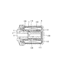
また、図5には、スプールバルブのスプール(図示せず)をその軸線方向に駆動するリニアソレノイド(従来例3)が開示されている(例えば、特許文献2参照)。
このリニアソレノイド(従来例3)は、シャフト5を介してスプールに連結したプランジャ6と、通電により磁力を発生するコイル7と、このコイル7の内周側に磁路を形成するステータコアと、コイル7の内周側に磁路を形成する有底円筒状のヨーク104とを備えている。
FIG. 5 discloses a linear solenoid (conventional example 3) that drives a spool (not shown) of a spool valve in the axial direction (see, for example, Patent Document 2).
This linear solenoid (conventional example 3) includes a
ステータコアは、互いに別体で構成されるステータコア101、102を備えている。また、ステータコア101とステータコア102との間には、ステータコア101、102間の磁束の漏れを遮断する磁気遮断部(エアギャップ118)が形成されている。
なお、ステータコア102の端部には、ヨーク104の第2凹部112の底面に密着する密着面を有するフランジ119が設けられている。また、プランジャ6をその軸線方向に摺動可能に嵌合支持する薄板カップ状の非磁性部品120が設置されている。
リニアソレノイド(従来例3)では、プランジャ6の外周とステータコア102の内周との隙間に非磁性部品120が嵌挿されている。
The stator core includes
A
In the linear solenoid (conventional example 3), a
[従来の技術の不具合]
ところで、リニアソレノイド(従来例1及び2)においては、プランジャ6とステータコア101、102との同軸ズレを防止するため、ステータコア101、102およびヨーク104に対して別体で形成される磁性部品117が必要となる。また、ステータコアを構成するステータコア101、102および磁気抵抗部103が一体化されているので、磁気抵抗部103の薄肉加工(またはレーザー微細孔加工等を含む)を廃止することができず、廉価にリニアソレノイドを製造できないという問題があった。
[Conventional technical problems]
By the way, in the linear solenoid (conventional examples 1 and 2), in order to prevent the coaxial displacement between the
一方、リニアソレノイド(従来例3)においては、プランジャ6とステータコア101、102との同軸ズレ、およびステータコア101とステータコア102との同軸ズレを防止するため、非磁性部品120が必要となる。これにより、リニアソレノイド(従来例3)が複雑な構造となると共に、組付工数が増大するため、廉価にリニアソレノイドを製造できないという問題があった。
なお、プランジャ6とステータコア101、102との同軸ズレや、ステータコア101とステータコア102との同軸ズレが生じると、ステータコア101、102に摺動可能に支持されるプランジャ6の摺動性が悪化する、あるいはカジリにより摺動できなくなるという問題があった。
On the other hand, in the linear solenoid (conventional example 3), the
If the coaxial displacement between the
本発明の目的は、第1固定コアに対する第2固定コアの相対的な軸ズレを吸収して、少なくとも第2固定コアに対する可動コアの摺動性を確保することのできるリニアソレノイドを提供することにある。また、少なくとも第2固定コアに対する可動コアの摺動性を損なうことなく、可動コアと第2固定コアとの間の磁気抵抗を最小化することのできるリニアソレノイドを提供することにある。 An object of the present invention is to provide a linear solenoid capable of absorbing a relative axial shift of the second fixed core with respect to the first fixed core and ensuring at least the slidability of the movable core with respect to the second fixed core. It is in. It is another object of the present invention to provide a linear solenoid capable of minimizing the magnetic resistance between the movable core and the second fixed core without impairing the slidability of the movable core with respect to at least the second fixed core.
請求項1に記載の発明(リニアソレノイド)は、軸線方向に移動可能な可動コアと、電力の供給を受けると可動コアを引き寄せる磁力を発生するコイルと、このコイルの内周側に磁路を形成する第1固定コアと、コイルの内周側に磁路を形成する第2固定コアと、コイルの外周側に磁路を形成するヨークとを備えている。
第1固定コアは、可動コアの軸線方向の一端側の周囲を取り囲むように設置されている。この第1固定コアは、(例えば有底筒状の)ヨーク(の開口端)に固定される結合部を設けている。
第2固定コアは、可動コアの軸線方向の他端側の周囲を取り囲むように設置されている。この第2固定コアは、第1固定コアに対して別体で構成されている。また、第2固定コアは、ヨークに当接する部分に球面凸部を設けている。この球面凸部は、リニアソレノイド(構成部品:少なくとも第2固定コア)の中心軸線上に位置する中心点を中心とした曲率半径を有する球面の一部で構成されている。
ヨークは、コイルの周囲を取り囲むように設置されている。このヨークは、第2固定コアに対して別体で構成されている。また、ヨークは、第2固定コアに当接する部分に、第2固定コアの球面凸部と密着可能な球面凹部を設けている。この球面凹部は、球面凸部と同一の中心点で、且つ球面凸部と同一曲率半径を有する球面の一部で構成されている。
The invention according to claim 1 (linear solenoid) includes a movable core that is movable in the axial direction, a coil that generates a magnetic force that draws the movable core when supplied with electric power, and a magnetic path on the inner peripheral side of the coil. A first fixed core to be formed, a second fixed core that forms a magnetic path on the inner peripheral side of the coil, and a yoke that forms a magnetic path on the outer peripheral side of the coil are provided.
The first fixed core is installed so as to surround the periphery of one end side in the axial direction of the movable core. The first fixed core is provided with a coupling portion that is fixed to a yoke (for example, a bottomed cylindrical shape).
The second fixed core is installed so as to surround the periphery of the other end side in the axial direction of the movable core. The second fixed core is configured separately from the first fixed core. In addition, the second fixed core is provided with a spherical convex portion at a portion in contact with the yoke. This spherical convex part is comprised by a part of spherical surface which has a curvature radius centering on the center point located on the center axis line of a linear solenoid (component: at least 2nd fixed core).
The yoke is installed so as to surround the coil. The yoke is configured separately from the second fixed core. In addition, the yoke is provided with a spherical concave portion that can be in close contact with the spherical convex portion of the second fixed core at a portion that contacts the second fixed core. The spherical concave portion is formed of a part of a spherical surface having the same center point as the spherical convex portion and having the same radius of curvature as the spherical convex portion.
請求項1に記載の発明によれば、第2固定コアの球面凸部とヨークの球面凹部とが密着状態を保ったまま、第2固定コアとヨークとの相対位置、例えば第2固定コアとヨークとの相対的な角度を変えることにより、第1固定コアに対する第2固定コアの相対的な同軸のズレを吸収できる。これにより、(例えば第1固定コアに対して分離独立して構成される)第2固定コアの加工精度やヨークとの組付嵌合の隙間により蓄積される第1固定コアと第2固定コアとの同軸のズレを吸収できるので、少なくとも第2固定コアに対する可動コアの摺動性を確保(向上)することが可能となる。
また、少なくとも第2固定コアに対する可動コアの摺動性を損なうことなく、可動コアと第2固定コアとの間のギャップを、例えば摺動クリアランス程度の狭小となるように詰めることができる。これにより、可動コアと第2固定コアとの間の磁気抵抗を最小化することが可能となるので、リニアソレノイドの製品性能の向上、つまり磁気効率の向上を図ることができる。
この結果、廉価な構造で、且つ効率的に磁気力を発生でき、小型化や省電力、高吸引力化に有益なリニアソレノイドを得ることができる。
According to the first aspect of the invention, the relative position between the second fixed core and the yoke, for example, the second fixed core, while the spherical convex portion of the second fixed core and the spherical concave portion of the yoke are kept in close contact with each other. By changing the relative angle with the yoke, the relative coaxial shift of the second fixed core with respect to the first fixed core can be absorbed. As a result, the first fixed core and the second fixed core accumulated due to the processing accuracy of the second fixed core (for example, configured to be separated and independent from the first fixed core) and the assembly fitting clearance with the yoke. Therefore, it is possible to ensure (improve) the slidability of the movable core with respect to at least the second fixed core.
In addition, the gap between the movable core and the second fixed core can be reduced to be as narrow as, for example, a sliding clearance without impairing the slidability of the movable core with respect to the second fixed core. As a result, the magnetic resistance between the movable core and the second fixed core can be minimized, so that the product performance of the linear solenoid, that is, the magnetic efficiency can be improved.
As a result, a magnetic solenoid can be efficiently generated with an inexpensive structure, and a linear solenoid useful for miniaturization, power saving, and high attraction force can be obtained.
請求項2に記載の発明によれば、第2固定コアにおけるヨークに当接する部分に、少なくとも第2固定コアの、可動コアを移動可能に保持する内周面の中心軸線と同軸を成す(凸)球面形状の球面凸部を設けている。
請求項3に記載の発明によれば、ヨークにおける第2固定コアに当接する部分に、少なくとも第1固定コアの、可動コアを移動可能に保持する内周面の中心軸線と同軸を成す(凹)球面形状の球面凹部を設けている。
請求項4に記載の発明によれば、第2固定コアの球面凸部とヨークの球面凹部とを密着させる方向に付勢する固定コア付勢手段を備えている。
According to the second aspect of the present invention, the portion of the second fixed core that is in contact with the yoke is at least coaxial with the central axis of the inner peripheral surface of the second fixed core that holds the movable core movably (convex). ) A spherical convex portion having a spherical shape is provided.
According to the third aspect of the present invention, at least a portion of the first fixed core that is in contact with the second fixed core in the yoke is coaxial with the central axis of the inner peripheral surface that holds the movable core in a movable manner. ) A spherical concave portion is provided.
According to the fourth aspect of the invention, the fixed core urging means for urging the spherical convex portion of the second fixed core and the spherical concave portion of the yoke in a close contact direction is provided.
請求項5に記載の発明によれば、請求項4に記載の固定コア付勢手段を備えず、第2固定コアの球面凸部とヨークの球面凹部とを密着状態で接着または溶接にて固定する固定手段を備えている。
具体的には、リニアソレノイドを構成する各部品を組み付けた後に、重力やコイルへの電力供給に伴う磁気吸着力を利用して、第2固定コアの球面凸部とヨークの球面凹部とを密着させた状態で、且つ第1、第2固定コアに対して可動コアが滑らかに摺動することを確認する。この状態で、第2固定コアの球面凸部とヨークの球面凹部との密着部分を固定コア溶接手段(レーザー溶接等)で固定しても良い。
According to the fifth aspect of the present invention, the fixed core urging means according to the fourth aspect is not provided, and the spherical convex portion of the second fixed core and the spherical concave portion of the yoke are fixed by adhesion or welding in a close contact state. Fixing means to be provided.
Specifically, after assembling the parts that make up the linear solenoid, the spherical convex part of the second fixed core and the spherical concave part of the yoke are brought into close contact with each other by using the magnetic attraction force accompanying gravity and power supply to the coil. In this state, it is confirmed that the movable core slides smoothly with respect to the first and second fixed cores. In this state, the contact portion between the spherical convex portion of the second fixed core and the spherical concave portion of the yoke may be fixed by a fixed core welding means (laser welding or the like).
請求項6に記載の発明によれば、可動コアと第1固定コアとの間に非磁性体よりなる摺動膜または部材を備えている。
請求項7に記載の発明によれば、第1固定コアに摺動膜または部材を設けている。
請求項8に記載の発明によれば、可動コアと第2固定コアとの間に非磁性体よりなる摺動膜または部材を備えている。
請求項9に記載の発明によれば、第2固定コアに摺動膜または部材を設けている。
請求項10に記載の発明によれば、可動コアに摺動膜または部材を設けている。
これによって、第1固定コアまたは第2固定コアに対する可動コアの摺動性を向上できる。
また、可動コアの摺動性を損なうことなく、可動コアと第1固定コアまたは第2固定コアとの間のギャップを、例えば摺動クリアランス程度の狭小となるように詰めることができる。これにより、可動コアと第1固定コアまたは第2固定コアとの間の磁気抵抗を最小化することが可能となるので、リニアソレノイドの製品性能の向上、つまり磁気効率の向上を図ることができる。
According to the sixth aspect of the present invention, the sliding film or member made of a nonmagnetic material is provided between the movable core and the first fixed core.
According to invention of
According to the eighth aspect of the present invention, the sliding film or member made of a nonmagnetic material is provided between the movable core and the second fixed core.
According to invention of Claim 9, the sliding film or member is provided in the 2nd fixed core.
According to invention of
Thereby, the slidability of the movable core with respect to the first fixed core or the second fixed core can be improved.
Further, the gap between the movable core and the first fixed core or the second fixed core can be reduced so as to be as narrow as, for example, a sliding clearance without impairing the slidability of the movable core. As a result, the magnetic resistance between the movable core and the first fixed core or the second fixed core can be minimized, so that the product performance of the linear solenoid, that is, the magnetic efficiency can be improved. .
請求項11に記載の発明によれば、第1固定コアに、コイルの発生磁力により可動コアを(その軸線方向の一方側に吸引する)引き寄せる磁気吸引部を設けている。
請求項12に記載の発明によれば、可動コアとの間に第1ギャップ(例えばメインギャップ)を形成する(内周部を有する)第1固定コアを備えている。
請求項13に記載の発明によれば、可動コアをその移動方向に往復摺動可能に支持する第1摺動内周面を有する第1固定コアを備えている。
請求項14に記載の発明によれば、可動コアとの間に第2ギャップ(例えばサイドギャップ)を形成する(内周部を有する)第2固定コアを備えている。
請求項15に記載の発明によれば、可動コアをその軸線方向に往復摺動可能に支持する第2摺動内周面を有する第2固定コアを備えている。
According to the eleventh aspect of the present invention, the first fixed core is provided with the magnetic attraction portion that draws the movable core (attracts to one side in the axial direction) by the magnetic force generated by the coil.
According to the twelfth aspect of the invention, the first fixed core (having the inner peripheral portion) is provided (for example, the main gap) is formed between the movable core and the first fixed core.
According to a thirteenth aspect of the present invention, the first fixed core having the first sliding inner peripheral surface that supports the movable core so as to be reciprocally slidable in the moving direction is provided.
According to the fourteenth aspect of the present invention, the second fixed core is formed (having an inner peripheral portion) that forms a second gap (for example, a side gap) between the movable core and the movable core.
According to the fifteenth aspect of the present invention, the second fixed core having the second sliding inner peripheral surface that supports the movable core so as to be slidable in the axial direction is provided.
以下、本発明の実施の形態を、図面に基づいて詳細に説明する。
本発明は、第1固定コアに対する第2固定コアの部品の嵌合隙間や組み付け変形等により生じる相対的な軸ズレを吸収して、少なくとも第2固定コアに対する可動コアの摺動性を確保するという目的、また、少なくとも第2固定コアに対する可動コアの摺動性を損なうことなく、可動コアと第2固定コアとの間の磁気抵抗を最小化するという目的を、第2固定コアの球面凸部を、少なくとも第2固定コアの、可動コアを移動可能に保持する内周面の中心軸線上と同軸に位置する中心点を中心とした曲率半径を有する球面の一部で構成し、また、ヨークの球面凹部を、球面凸部と同一の中心点で、且つ球面凸部と同一曲率半径を有する球面の一部で構成し、第1固定コアに対する第2固定コアの相対的な同軸のズレを角度がズレることで吸収し、第2固定コアの球面凸部とヨークの球面凹部との密着状態を可能とした構造を採用することで実現した。
Hereinafter, embodiments of the present invention will be described in detail with reference to the drawings.
The present invention absorbs relative axial misalignment caused by a fitting clearance or assembly deformation of a component of the second fixed core with respect to the first fixed core, and ensures at least the slidability of the movable core with respect to the second fixed core. The objective of minimizing the magnetic resistance between the movable core and the second fixed core without impairing the slidability of the movable core with respect to the second fixed core at least is the spherical convex of the second fixed core. The portion is constituted by a part of a spherical surface having a radius of curvature centered on a central point located coaxially with the central axis of the inner peripheral surface of the at least second fixed core that movably holds the movable core, and The spherical concave portion of the yoke is constituted by a part of a spherical surface having the same center point as the spherical convex portion and the same radius of curvature as the spherical convex portion, and the relative coaxial shift of the second fixed core with respect to the first fixed core. Absorbs the angle deviation It was achieved by adopting a possible a structure in a close contact state between the spherical protrusion and the yoke of the spherical recess of the second fixed core.
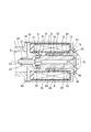
図1は本発明の実施例1を示したもので、リニアソレノイドを示した図である。
本実施例の油圧制御装置は、自動車に搭載される自動変速機(オートマチックトランスミッション)の変速制御に使用されるものである。
油圧制御装置は、複数の油路を有するバルブボディ(図示せず)と、このバルブボディに取り付けられて、バルブボディの油路と共に油圧回路を構成する複数の電磁油圧制御弁と、ドライバー等から要求された変速状態を実現するように複数の電磁油圧制御弁を制御する制御ユニット(TCU)とを備えている。
FIG. 1 shows a first embodiment of the present invention and is a diagram showing a linear solenoid.
The hydraulic control apparatus according to the present embodiment is used for shift control of an automatic transmission (automatic transmission) mounted on an automobile.
The hydraulic control device includes a valve body (not shown) having a plurality of oil passages, a plurality of electromagnetic hydraulic control valves attached to the valve body and forming a hydraulic circuit together with the oil passages of the valve body, and a driver. And a control unit (TCU) for controlling a plurality of electrohydraulic control valves so as to realize the requested shift state.
バルブボディは、複数の電磁油圧制御弁を保持するバルブ保持部材であって、複数の電磁油圧制御弁を挿入する複数のバルブ挿入溝、およびこのバルブ挿入溝にそれぞれ連通する油路を有している。
TCUは、バルブボディに搭載されて、複数の電磁油圧制御弁を駆動することで、自動変速機の変速制御等を行う。
バルブボディおよびTCUは、トランスミッションケースの下部に取り付けられるオイルパン内に設置されている。
The valve body is a valve holding member that holds a plurality of electrohydraulic control valves, and has a plurality of valve insertion grooves into which the plurality of electrohydraulic control valves are inserted, and oil passages that respectively communicate with the valve insertion grooves. Yes.
The TCU is mounted on the valve body and drives a plurality of electromagnetic hydraulic control valves to perform shift control of the automatic transmission.
The valve body and the TCU are installed in an oil pan attached to the lower part of the transmission case.
複数の電磁油圧制御弁のうちの少なくとも1つの電磁油圧制御弁は、内燃機関(エンジン)により駆動されるオイルポンプ(図示せず)によって発生した油圧(ライン圧)を調圧して自動変速機に組み込まれる摩擦係合要素(クラッチまたはブレーキ)へ送るソレノイドバルブである。
電磁油圧制御弁は、ライン油圧を入力すると共に、入力したライン油圧を調圧して出力するスプールバルブと、このスプールバルブを駆動する電磁アクチュエータであるリニアソレノイドとを備えている。
At least one of the plurality of electromagnetic hydraulic control valves adjusts the hydraulic pressure (line pressure) generated by an oil pump (not shown) driven by the internal combustion engine (engine) to the automatic transmission. It is a solenoid valve that feeds a friction engagement element (clutch or brake) to be incorporated.
The electromagnetic hydraulic control valve includes a spool valve that inputs the line hydraulic pressure, regulates and outputs the input line hydraulic pressure, and a linear solenoid that is an electromagnetic actuator that drives the spool valve.
スプールバルブは、バルブボディのバルブ挿入溝(凹部)内に嵌合配置される円筒状のスリーブ1と、このスリーブ1のスプール孔2内に往復移動(摺動)可能に嵌合配置されるスプール3と、このスプール3をリニアソレノイド側(図示右側)へ付勢するリターンスプリング4とを備えている(図3及び4参照)。
スリーブ1の内部には、軸線方向の一端側から他端側まで延びるスプール孔2が形成されている。このスリーブ1には、作動油(オイル)が流出入する複数のポートとして、油圧発生手段であるオイルポンプから油路や切替弁等を介して油圧が供給される入力ポートと、スプールバルブで調圧した出力圧が出力される出力ポートと、低圧側(オイルパン等)に連通するドレンポートと、出力ポートに連通するフィードバックポートが形成されている。
The spool valve is a
A
スプール3は、スプールバルブの弁体(バルブ本体)を構成するもので、スリーブ1のスプール孔2内に往復摺動可能に嵌合支持されている。このスプール3の軸線方向の他端側端部(ソレノイド側端部)は、スプール孔2の内部からリニアソレノイドの内部まで延びるシャフト5の軸方向の一端面と当接している。このシャフト5の軸方向の他端面は、プランジャ6の接触部に当接している。これにより、スプールバルブは、プランジャ6がその軸線方向に移動することで、シャフト5を介してスプール3をその軸線方向へ駆動するように構成される。
また、スプール3は、複数のポート間の連通状態を制御する複数のランドを備えている。これらのランドの外周面は、スリーブ1のスプール孔2の孔壁面と摺動する摺動部(摺動面)となっている。なお、複数のランドの摺動面とスリーブ1のスプール孔2の孔壁面との間には、スプール3の往復摺動を可能とするための摺動クリアランスが形成されている。
The
Further, the
スプールバルブは、リニアソレノイドの作動によってスプール3をその軸線方向に変位させることで、入力ポートと出力ポートとの連通面積と、出力ポートと排出ポートとの連通面積とが変化する。これにより、出力ポートに発生する油圧が調圧される。
リターンスプリング4は、スプール3のソレノイド側に対して逆側端部に螺合された調整ネジ(プラグ)とスプール3との軸方向隙間に収容されたコイル状のスプリングである。リターンスプリング4のバネ荷重は、調整ネジの捩じ込み量(螺合量)に応じて調整可能となっている。
In the spool valve, the communication area between the input port and the output port and the communication area between the output port and the discharge port are changed by displacing the
The return spring 4 is a coiled spring that is accommodated in an axial clearance between the
リニアソレノイドは、スプール3と一体移動可能に連結した非磁性体製のシャフト5と、スプール3およびシャフト5と一体移動可能に連結した磁性体製のプランジャ(磁気可動子)6と、通電されると周囲に磁束を発生するコイル7と、外周にコイル7を巻装した合成樹脂製のボビン8と、コイル7と外部回路(外部電源や外部制御回路:TCU)との接続を行うための外部接続用コネクタ9(図3及び4参照)と、コイル7への通電に伴って形成される磁気回路の一部を構成する磁気固定子(円筒状の第1、第2ステータコア(以下ステータコア11、12と言う)および有底円筒形状のヨーク13)とを備えている。
The linear solenoid is energized with a
ステータコア11は、ボビン8の軸線方向の一端面との間に、コイル7とボビン8よりなるコイルアッセンブリおよびステータコア12をヨーク13の底面側に付勢するウェーブワッシャ(固定コア付勢手段)14を備えている。また、プランジャ6の外周には、非磁性体よりなる円環状の摺動部材15が組み付けられている。また、プランジャ6の軸線方向の一端面には、非磁性体よりなる摺動膜16が設けられている。また、プランジャ6の外周面には、非磁性体よりなる摺動膜17が設けられている。
The stator core 11 has a coil assembly including the
本実施例の電磁アクチュエータは、ステータコア11、12にプランジャ6を直接往復摺動させるタイプで、特にプランジャ6とステータコア12との間に形成される径方向空隙(サイドギャップ:SG)を比較的に小さく、同芯的に配置したタイプのリニアソレノイドである。
プランジャ6は、コイル7への通電に伴って形成される磁気回路の一部を構成する磁性部品であって、ステータコア11、12の各第1、第2摺動部21、22内をその軸線方向に往復摺動可能な可動コア(ムービングコア)である。このプランジャ6は、コイル7が通電されると励磁(磁化)される磁性金属(例えば鉄等の強磁性材料)よりなる円柱形状の磁性移動体である。
The electromagnetic actuator of the present embodiment is a type in which the
The
プランジャ6は、ステータコア11、12の各第1、第2摺動部21、22の内周面に往復摺動可能に支持されており、ステータコア11、12の各第1、第2摺動部21、22の内周面と直接摺動するものである。
ここで、シャフト5は、プランジャ6の軸線方向の一端面に当接して、スプール3とプランジャ6とを連結する連結部である。このシャフト5は、ステータコア11の軸受け部23の内周面に往復摺動可能に支持されており、ステータコア11の軸受け部23の内周面と直接摺動するものである。
The
Here, the
プランジャ6は、シャフト5の端面と当接する接続部を有する径小部24、およびこの径小部24よりも外径が大きい胴体部(径大部)25等を有している。
径小部24は、径大部25よりもシャフト側端部に設けられている。
径大部25は、ステータコア11、12の各第1、第2摺動部21、22の内周面との間に摺動クリアランスを形成する。
また、プランジャ6は、スプール3に伝わるリターンスプリング4の付勢力によってスプール3、シャフト5と共に、ヨーク13の底面側へ付勢される。また、プランジャ6には、ステータコア11、12内での変位に伴うプランジャ前後空間の空気の流動を確保するために、プランジャ両端面を連通する呼吸孔26が軸線方向に設けられている。
The
The
The large-
The
コイル7は、電力の供給を受けると(通電されると)、プランジャ6を引き寄せる磁力を発生する磁束発生手段(磁力発生手段)である。コイル7が通電されると、プランジャ6、ステータコア11、12およびヨーク13を磁束が集中して通る磁気回路が形成される。
コイル7は、磁力によってスプール3、シャフト5およびプランジャ6を、スリーブ1とスプール3の軸線方向の一方側(前方側)へ駆動するものである。
コイル7は、絶縁性を有する合成樹脂製のボビン8に、絶縁被膜を施した導線を複数回巻装したソレノイドコイルである。また、コイル7は、ボビン8に巻装されたコイル部、およびこのコイル部より引き出された一対のコイル端末リードを有している。
一対のコイル端末リードは、外部接続用コネクタ9のターミナル(外部接続端子)を介して、外部回路(外部電源や外部制御回路:TCU)と接続されている。なお、コイル7の外周部、およびコイル7とターミナルとの導通接合部は、絶縁性を有する樹脂モールド材により被覆されて保護されている。
The
The
The
The pair of coil terminal leads are connected to an external circuit (external power supply or external control circuit: TCU) via a terminal (external connection terminal) of the external connection connector 9. Note that the outer peripheral portion of the
磁気固定子は、コイル7が通電されると励磁(磁化)される磁性金属(例えば鉄等の強磁性材料)よりなる磁性固定体であって、コイル7の内周側に磁路を形成する円筒状の第1、第2ステータコア11、12と、コイル7の外周側に磁路を形成する有底円筒状のヨーク13とによって構成されている。
ステータコア11は、ステータコア12およびヨーク13に対して別体で構成されて、プランジャ6の軸線方向の一端側の周囲を周方向に取り囲むように設置されている。このステータコア11には、プランジャ6が直接摺動する円筒状の第1摺動部21、およびシャフト5が直接摺動する円筒状の軸受け部23が一体的に形成されている。
The magnetic stator is a magnetic stator made of a magnetic metal (for example, a ferromagnetic material such as iron) that is excited (magnetized) when the
The stator core 11 is configured separately from the
第1摺動部21は、軸受け部23の外周よりも半径方向(放射方向)の外側(外周側)に設けられている。この第1摺動部21は、プランジャ6に対して同芯的(同軸的)に配置されて、プランジャ6をその軸線方向に往復摺動可能に支持する第1摺動内周面31を有している。具体的には、第1摺動部21の第1摺動内周面31にプランジャ6の摺動部材15が直接摺動するようになっている。
軸受け部23は、第1摺動部21の内周よりも半径方向(放射方向)の内側(内周側)に設けられている。この軸受け部23は、シャフト5に対して同芯的(同軸的)に配置されて、シャフト5をその軸線方向に往復摺動可能に支持する軸受け内周面33を有している。この軸受け内周面33は、ステータコア11の第1摺動内周面31およびステータコア12の第2摺動内周面32よりも内径が小さくなっている。また、軸受け部23には、ステータコア11内での変位に伴うシャフト前後空間の空気の流動を確保するために、シャフト両端面を連通する呼吸孔34が軸線方向に設けられている。
The first sliding
The bearing
ステータコア11には、プランジャ6の外周との間にメインギャップ(径方向空隙、第1ギャップ)MGを形成する円環状の磁気吸引部41、およびヨーク13の開口端側に位置決めされた状態で固定される円環状のフランジ(鍔形状部、結合部)42が一体的に形成されている。
磁気吸引部41は、第1摺動部21の軸線方向のステータ側端部に一体的に設けられて、コイル7を通電するとプランジャ6をその軸線方向の一方側に引き寄せる。
フランジ42は、第1摺動部21の外周から半径方向(放射方向)の外側(外周側)に設けられている。このフランジ42は、コイルアッセンブリ、特にコイル7の軸線方向の一端側を覆うように設けられている。また、フランジ42は、スリーブ1のフランジ10と一緒にヨーク13の開口端に嵌合した状態でカシメを行うことで、スリーブ1、ステータコア11およびヨーク13が固定される。これにより、スリーブ1、ステータコア11およびヨーク13は、同軸(同芯)上に配置される。
The stator core 11 is fixed in a state where the stator core 11 is positioned on the opening end side of the
The
The
ステータコア12は、ステータコア11およびヨーク13に対して別体で構成されて、プランジャ6の軸線方向の他端側の周囲を周方向に取り囲むように設置されている。このステータコア12には、プランジャ6の外周との間にサイドギャップ(径方向空隙、第2ギャップ)SGを形成すると共に、プランジャ6が直接摺動する円筒状の第2摺動部22、およびこの第2摺動部22の端部(円筒端部)からヨーク13の底面側に向かって突出する円環状のフランジ(凸部、鍔形状部)43が一体的に形成されている。
第2摺動部22は、プランジャ6、ステータコア11の第1摺動部21に対して同芯的(同軸的)に設けられている。この第2摺動部22は、プランジャ6をその軸線方向に往復摺動可能に支持する第2摺動内周面32を有している。具体的には、第2摺動部22の第2摺動内周面32にプランジャ6の摺動膜17が直接摺動するようになっている。
なお、第2摺動部22は、ヨーク13からプランジャ6へ磁束を伝える磁気受け渡し部を構成している。
The
The second sliding
The second sliding
ヨーク13は、ステータコア11、12に対して別体で構成されて、コイル7の周囲を周方向に取り囲むように設置されている。このヨーク13の内部には、ヨーク13以外のリニアソレノイド構成部品(シャフト5、プランジャ6、コイル7を巻装したボビン8、ステータコア11、12およびウェーブワッシャ14等)を収容するソレノイド収納空間44が形成されている。
ヨーク13は、コイル7の外周を覆う円筒状の外壁部(側壁部)を有している。この外壁部の軸線方向の一端は、開放された開口端となっている。このヨーク13の外壁部の開口端には、薄肉部45が形成されている。
外壁部の軸線方向の他端には、外壁部の軸線方向の他端側の開口部を閉塞する底壁部が設けられている。この底壁部は、コイルアッセンブリ、特にコイル7の軸線方向の他端側を覆うように設けられている。この底壁部には、外部に向かって凹んだ(凸な)収容凹部46が設けられている。この収容凹部46には、プランジャ6の軸線方向の他端、ステータコア12のフランジ43が収容されている。
The
The
At the other end in the axial direction of the outer wall portion, a bottom wall portion that closes the opening on the other end side in the axial direction of the outer wall portion is provided. The bottom wall portion is provided so as to cover the coil assembly, in particular, the other end side of the
以上のように構成されたリニアソレノイドでは、ターミナルを介してコイル7が通電されると、ヨーク13、ステータコア12、プランジャ6、ステータコア11、ヨーク13の順にコイル7の周囲を周回するように磁束が流れる磁気回路(磁路)が形成される。これにより、ステータコア11の磁気吸引部41とプランジャ6との間に磁気吸引力が作用してプランジャ6が吸引される。
ここで、プランジャ6の先端面には、ステータコア11の軸受け部23の軸受け内周面33を軸線方向に往復摺動可能なシャフト5が当接しているので、プランジャ6の吸引に伴ってシャフト5が軸線方向の一方側に押し出される。この結果、スプールバルブのスプール3がリニアソレノイドにより駆動される。
In the linear solenoid configured as described above, when the
Here, since the
[実施例1の特徴]
本実施例のリニアソレノイドでは、プランジャ6との間にメインギャップMGを形成するステータコア11が「ステータコアのメインギャップ部」を構成し、また、プランジャ6との間にサイドギャップSGを形成するステータコア12が「ステータコアのサイドギャップ部」を構成している。
リニアソレノイドは、プランジャ6とステータコア11との間の磁気力を増加するという目的で、メインギャップMGが比較的に小さく構成されて、第1摺動部21の第1摺動内周面31にプランジャ6が直接摺動するようになっている。
[Features of Example 1]
In the linear solenoid of this embodiment, the stator core 11 that forms the main gap MG with the
The linear solenoid has a relatively small main gap MG for the purpose of increasing the magnetic force between the
リニアソレノイドは、プランジャ6とステータコア12との間の磁気力を増加するという目的で、サイドギャップSGが比較的に小さく構成されて、第2摺動部22の第2摺動内周面32にプランジャ6が直接摺動するようになっている。
リニアソレノイドは、ステータコア11とステータコア12とが内径側で分離しており、磁束(磁気)の漏洩(漏れ)を遮断する薄肉部や磁気遮断部を備える必要が無い。
The linear solenoid has a relatively small side gap SG for the purpose of increasing the magnetic force between the
In the linear solenoid, the stator core 11 and the
ここで、プランジャ6とステータコア11との摺動性を向上させるという目的で、プランジャ6の径小部24の外周に円環(リング)状の摺動部材15が圧入やかしめ加工等を用いて接合されている。なお、摺動部材15は、耐油性、摺動性を有する低摩擦係数の非磁性体(例えば錫含有アルミニウム合金、燐青銅等)よりなる非磁性金属である。また、摺動性を有しない一般の金属に、窒化チタンや窒化クロム等の金属化合物のコーティング、タングステンカーバイトコーティング、DLCコーティングのような表面処理を施し、摺動性および耐摩耗性を付与しても良い。
Here, for the purpose of improving the slidability between the
また、プランジャ6とステータコア12との摺動性を向上させるという目的で、プランジャ6の径大部25の外周に所定の膜厚を有する摺動膜17が薄膜形成されている。なお、摺動膜16、17は、耐摩耗性、摺動性を有する低摩擦係数の非磁性体(例えば二硫化モリブデン塗膜、フッ素樹脂膜、DLC膜等)よりなる非磁性薄膜である。
A sliding
ここで、ステータコア11とヨーク13との磁気接続部は、ステータコア11のフランジ42の外周面(密着面)とヨーク13の薄肉部45の内周面(密着面)との第1密着部分に設けられている。
また、ステータコア12とヨーク13との磁気接続部は、ステータコア12のフランジ43の密着面とヨーク13の収容凹部46の密着面との第2密着部分に設けられている。
Here, the magnetic connection portion between the stator core 11 and the
Further, the magnetic connection portion between the
また、ステータコア12は、ヨーク13の密着面に当接する部分であるフランジ43の外周面に、プランジャ6、ステータコア11、12およびヨーク13の中心軸線CLと同軸を成す凸球面形状の球面凸部51を備えている。この球面凸部51は、リニアソレノイド構成部品(少なくともステータコア11、ヨーク13)の中心軸線CL上に位置する曲率中心点Oを中心とした曲率半径r(SR値)を有する球面の一部で構成されている。
また、ヨーク13は、ステータコア12に当接する部分である収容凹部46の内周面に、リニアソレノイド構成部品(少なくともステータコア11、ヨーク13)の中心軸線CLと同軸を成し、ステータコア12の球面凸部51と密着可能な凹球面形状の球面凹部52を備えている。この球面凹部52は、球面凸部51と同一の曲率中心点Oで、且つ球面凸部51と略同一曲率半径r(SR値)を有する球面の一部で構成されている。
In addition, the
Further, the
コイル7が巻装されるボビン8の軸線方向の一端には、ウェーブワッシャ14からバネ荷重を受ける円環状の荷重受け部61が設けられている。また、ボビン8の軸線方向の他端には、ステータコア12のフランジ43側に向かって突出し、フランジ43に当接可能な円環状の突起62が一体的に形成されている。この突起62は、ステータコア12のフランジ43へウェーブワッシャ14のバネ荷重を付与する荷重付与部である。
また、ステータコア12のフランジ43には、突起62側に向かって突出し、突起62が当接可能な円環状の突起63が一体的に設けられている。この突起63は、ボビン8の突起62からウェーブワッシャ14のバネ荷重を受ける荷重受け部である。
At one end in the axial direction of the
The
また、リニアソレノイドは、ボビン8の軸線方向の一端面とステータコア11のフランジ42の他端面(対向面)との間にウェーブワッシャ14を備えている。このウェーブワッシャ14は、コイルアッセンブリ(コイル7、ボビン8等)を介して、ヨーク13の球面凹部52の凹球面(密着面)に対してステータコア12の球面凸部51の凸球面(密着面)を密着させる方向(図示右方向)に付勢する固定コア付勢手段である。
なお、本実施例のリニアソレノイドは、ボビン8の突起62とステータコア12のフランジ43の突起63とが当接可能な構造を採用しているので、ウェーブワッシャ14が図示右方向にコイルアッセンブリ(特にコイル7を巻装したボビン8)を付勢すると、ステータコア11も一緒に図示右方向に移動し、ステータコア12の球面凸部51の密着面がヨーク13の球面凹部52の密着面に密着(押圧接触)する。
The linear solenoid includes a
The linear solenoid of this embodiment employs a structure in which the
ここで、スプールバルブとリニアソレノイドとを組み付ける組み付け方法としては、先ず円筒状のスリーブ1のスプール孔2内に少なくともスプール3を組み込む。
一方、有底円筒状のヨーク13のソレノイド収納空間44内に、ヨーク13以外のリニアソレノイド構成部品(シャフト5、プランジャ6、コイル7を巻装したボビン8、ステータコア11、12およびウェーブワッシャ14)を組み込む。
その後に、スリーブ1の開口端に設けられたフランジ10の結合端面とステータコア11のフランジ42の結合端面とを密着させ、更に、フランジ10、42の外周をヨーク13の開口端に設けられる薄肉部45の内周に嵌合させた状態で、薄肉部45をカシメることで、スプールバルブとリニアソレノイドとが強固に結合される。
このとき、ステータコア11は、ヨーク13内で固定される。また、コイル7を巻装したボビン8およびステータコア12は、ウェーブワッシャ14の付勢力でヨーク13の底壁部の底面側に押し付けられており、ステータコア12の球面凸部51とヨーク13の球面凹部52とを設けたことによる自動調芯作用により、スリーブ1、コイル7を巻装したボビン8、ステータコア11、12およびヨーク13が同軸上に配置される。
Here, as an assembling method for assembling the spool valve and the linear solenoid, first, at least the
On the other hand, in the
Thereafter, the coupling end surface of the
At this time, the stator core 11 is fixed in the
[実施例1の効果]
以上のように、本実施例の電磁油圧制御弁のスプールバルブを駆動するリニアソレノイドにおいては、ステータコア11とステータコア12とが内径側で分離しており、磁束(磁気)の漏洩(漏れ)を遮断する薄肉部や磁気遮断部を備える必要が無い。これによって、ステータコア11、12間の磁束の漏れを低減する加工(例えばステータコア11とステータコア12との間に薄肉部等やレーザー加工機による微細孔加工等の磁気抵抗部を形成する加工)を必要としないので、廉価にリニアソレノイドを製造できる。
[Effect of Example 1]
As described above, in the linear solenoid that drives the spool valve of the electromagnetic hydraulic control valve of the present embodiment, the stator core 11 and the
ここで、リニアソレノイドにおいては、ステータコア11の第1摺動部21の第1摺動内周面31と直接摺動するプランジャ6の径小部24の外周に、耐油性、摺動性(潤滑性)を有する非磁性体よりなる摺動部材15を圧入やかしめ加工等により固定している。
また、ステータコア12の第2摺動部22の第2摺動内周面32と直接摺動するプランジャ6の径大部25の外周に、耐油性、摺動性(潤滑性)を有する非磁性体よりなる摺動膜17を所定の膜厚で形成している。
Here, in the linear solenoid, oil resistance, slidability (lubrication) is provided on the outer periphery of the
Further, the outer periphery of the
これによって、ステータコア11に対するプランジャ6の摺動性を向上できるので、プランジャ6の摺動抵抗が減少し、応答性が向上する。
また、プランジャ6の摺動性を損なうことなく、プランジャ6の径大部25とステータコア11の磁気吸引部41との間のメインギャップMGを、例えば摺動クリアランス程度の狭小となるように詰めることができる。これにより、プランジャ6の径大部25とステータコア11の磁気吸引部41との間の磁気抵抗を最小化することが可能となるので、リニアソレノイドの製品性能の向上、つまり磁気効率の向上を図ることができる。
Thereby, since the slidability of the
Further, the main gap MG between the
また、ステータコア12に対するプランジャ6の摺動性を向上できるので、プランジャ6の摺動抵抗が減少し、応答性が向上する。
また、プランジャ6の摺動性を損なうことなく、プランジャ6の径大部25とステータコア12の第2摺動部(磁気受け渡し部)22との間のサイドギャップSGを、例えば摺動クリアランス程度の狭小となるように詰めることができる。これにより、プランジャ6の径大部25とステータコア12の第2摺動部22との間の磁気抵抗を最小化することが可能となるので、リニアソレノイドの製品性能の向上、つまり磁気効率の向上を図ることができる。
Moreover, since the slidability of the
Further, the side gap SG between the
また、リニアソレノイドにおいては、ステータコア12のフランジ43に凸球面形状の球面凸部51を設け、また、ヨーク13の収容凹部46に凹球面形状の球面凹部52を設け、ステータコア12とヨーク13との相対的な角度がずれた場合でも、ステータコア12の球面凸部51とヨーク13の球面凹部52との密着状態を維持できるように、コイル7とボビン8よりなるコイルアッセンブリを介して、ステータコア12の球面凸部51とヨーク13の球面凹部52とを密着させる方向(図示右方向)に付勢するウェーブワッシャ14を設けている。
Further, in the linear solenoid, a convex spherical spherical
これによって、ステータコア12の球面凸部51とヨーク13の球面凹部52とが密着状態を保ったまま、ステータコア12とヨーク13との相対位置、例えばステータコア12とヨーク13との相対的な角度が変わり、ヨーク13に対するステータコア12の相対的な角度のズレを吸収できる。これにより、ステータコア11に対して分離独立して構成されるステータコア12の加工精度や組付嵌合による、ステータコア11、12およびヨーク13の同軸のズレを吸収できるので、少なくともステータコア12に対するプランジャ6の摺動性を確保(向上)することが可能となる。
この結果、廉価な構造で、且つ効率的に磁気力を発生でき、小型化や省電力、高吸引力化に有益なリニアソレノイドを得ることができる。
Accordingly, the relative position between the
As a result, a magnetic solenoid can be efficiently generated with an inexpensive structure, and a linear solenoid useful for miniaturization, power saving, and high attraction force can be obtained.
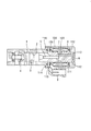
図2は本発明の実施例2を示したもので、リニアソレノイドを示した図である。
本実施例のリニアソレノイドにおいては、ステータコア11の第1摺動部21の内周面(第1摺動内周面31の孔壁面)と直接摺動するプランジャ6の径小部24の外周に、耐油性、摺動性(潤滑性)を有する非磁性体よりなる円環状の摺動部材15をレーザー溶接等により固定している。
また、プランジャ6の径大部25の外周面と直接摺動するステータコア12の第2摺動部21の内周に円筒状の凹部64を設け、この凹部64内に、耐油性、摺動性(潤滑性)を有する非磁性体よりなる円環状の摺動部材18を圧入等により固定している。また、フッ素樹脂等の摺動材を直接コーティングしても良いし、メッキやコーティングした部材を圧入するものであっても良い。
FIG. 2 shows a second embodiment of the present invention and shows a linear solenoid.
In the linear solenoid of the present embodiment, the outer periphery of the
Further, a
また、リニアソレノイドにおいては、ステータコア12の球面凸部51とヨーク13の球面凹部52とを密着状態でレーザー溶接を用いて接合するレーザー溶接部(固定コア溶接手段)19を設けている。
具体的には、リニアソレノイドを構成する各構成部品を組み付けた後に、重力やコイル7への電力供給に伴う磁気吸着力を利用して、ステータコア12の球面凸部51とヨーク13の球面凹部52とを密着させた状態で、且つステータコア11、12の各第1、第2摺動内周面31、32に対してプランジャ6が滑らかに摺動することを確認する。この状態で、ステータコア12の球面凸部51とヨーク13の球面凹部52との密着部分をレーザー溶接で接合させた構造を採用している。
以上のように、本実施例のリニアソレノイドにおいては、実施例1と同様な効果を達成することができる。
Further, the linear solenoid is provided with a laser welded portion (fixed core welding means) 19 for joining the spherical
Specifically, after assembling the respective components constituting the linear solenoid, the spherical
As described above, the linear solenoid according to the present embodiment can achieve the same effects as those of the first embodiment.
[変形例]
本実施例では、本発明のリニアソレノイドを、自動車の自動変速機の油圧制御を行う油圧制御装置に組み込まれるスプールバルブを駆動するリニアソレノイドに適用しているが、本発明のリニアソレノイドを、流体圧制御、流量制御、流路切替制御に用いるスプールバルブを駆動するリニアソレノイドに適用しても良い。
また、スプールバルブの代わりに、ボールバルブ等の他の形状のバルブを駆動するリニアソレノイドに本発明を適用しても良い。
また、シャフト5とプランジャ6とが一体構造の可動コアに本発明の構造を適用しても良い。また、シャフト5を磁性体で構成しても良い。
[Modification]
In this embodiment, the linear solenoid of the present invention is applied to a linear solenoid that drives a spool valve incorporated in a hydraulic control device that performs hydraulic control of an automatic transmission of an automobile. You may apply to the linear solenoid which drives the spool valve used for pressure control, flow control, and flow path switching control.
Further, the present invention may be applied to a linear solenoid that drives a valve of another shape such as a ball valve instead of the spool valve.
The structure of the present invention may be applied to a movable core in which the
本実施例では、ステータコア12の球面凸部51とヨーク13の球面凹部52とを密着させる方向に付勢する固定コア付勢手段として、コイルアッセンブリ(コイル7、ボビン8等)を介して、ヨーク13の球面凹部52の凹球面(密着面)に対してステータコア12の球面凸部51の凸球面(密着面)を密着させる方向に付勢するウェーブワッシャ14を採用しているが、固定コア付勢手段として、Oリング、板バネ、ウェーブワッシャ、コイル状のスプリング等の弾性体を採用しても良い。
本実施例では、ステータコア12のフランジ(鍔形状部)43の外周面に凸球面形状の球面凸部51を設けているが、ステータコア12の第2摺動部(円筒部)22の円筒端部に凸球面形状の球面凸部51を設けても良い。
本実施例では、ステータコア11とヨーク13とが別体の構造で、ヨーク13の収容凹部46の内周面に凹球面形状の球面凹部52を設けた構造で説明しているが、ステータコア11とヨーク13とが一体の構造であっても良く、この場合、コイルアッセンブリがヨーク13の後端側(ステータコア12側)から組み付けられる形状となるが、ヨーク13の外周の後端部に球面凹部52を設けても良い。
In this embodiment, the fixed core urging means for urging the spherical
In the present embodiment, the convex spherical surface
In the present embodiment, the stator core 11 and the
1 スリーブ
2 スリーブのスプール孔
3 スプール(バルブ)
4 リターンスプリング
5 シャフト
6 プランジャ
7 コイル
8 ボビン
10 スリーブのフランジ
11 ステータコア(第1固定コア)
12 ステータコア(第2固定コア)
13 ヨーク
14 ウェーブワッシャ(固定コア付勢手段)
15 摺動部材
16 摺動膜
17 摺動膜
18 摺動部材
19 レーザー溶接部(固定コア溶接手段)
21 第1摺動部
22 第2摺動部
23 軸受け部
31 第1摺動内周面
32 第2摺動内周面
33 軸受け内周面
41 ステータ(第1固定コア)の磁気吸引部
42 ステータ(第1固定コア)のフランジ(結合部)
51 ステータ(第2固定コア)の球面凸部
52 ヨークの球面凹部
1
4
12 Stator core (second fixed core)
13
DESCRIPTION OF
21
51 Spherical convex portion of stator (second fixed core) 52 Spherical concave portion of yoke
Claims (15)
(b)電力の供給を受けると前記可動コアを引き寄せる磁力を発生するコイルと、
(c)前記可動コアの軸線方向の一端側の周囲を取り囲むように設置されて、前記コイルの内周側に磁路を形成する第1固定コアと、
(d)前記可動コアの軸線方向の他端側の周囲を取り囲むように設置されて、前記コイルの内周側に磁路を形成すると共に、前記第1固定コアに対して別体で構成された第2固定コアと、
(e)前記コイルの周囲を取り囲むように設置されて、前記コイルの外周側に磁路を形成すると共に、前記第2固定コアに対して別体で構成されたヨークと
を備えたリニアソレノイドにおいて、
前記第1固定コアは、前記ヨークに固定される結合部を有し、
前記第2固定コアは、前記ヨークに当接する部分に設けられた球面凸部を有し、 前記ヨークは、前記第2固定コアに当接する部分に設けられ、前記球面凸部と密着可能な球面凹部を有し、
前記球面凸部は、前記リニアソレノイドの中心軸線上に位置する中心点を中心とした曲率半径を有する球面の一部で構成されており、
前記球面凹部は、前記球面凸部と同一の中心点で、且つ前記球面凸部と略同一曲率半径を有する球面の一部で構成されていることを特徴とするリニアソレノイド。 (A) a movable core movable in the axial direction;
(B) a coil that generates a magnetic force to attract the movable core when supplied with power;
(C) a first fixed core that is installed so as to surround the periphery of one end side in the axial direction of the movable core, and forms a magnetic path on the inner peripheral side of the coil;
(D) It is installed so as to surround the periphery of the other end side in the axial direction of the movable core, forms a magnetic path on the inner peripheral side of the coil, and is configured separately from the first fixed core. A second fixed core;
(E) In a linear solenoid that is installed so as to surround the coil, forms a magnetic path on the outer peripheral side of the coil, and includes a yoke formed separately from the second fixed core. ,
The first fixed core has a coupling portion fixed to the yoke,
The second fixed core has a spherical convex portion provided at a portion that contacts the yoke, and the yoke is provided at a portion that contacts the second fixed core and can be in close contact with the spherical convex portion. Having a recess,
The spherical convex portion is composed of a part of a spherical surface having a radius of curvature centered on a central point located on the central axis of the linear solenoid,
The linear solenoid is characterized in that the spherical concave portion is constituted by a part of a spherical surface having the same center point as the spherical convex portion and having substantially the same radius of curvature as the spherical convex portion.
前記球面凸部は、前記第2固定コアの、前記可動コアを移動可能に保持する内周面の中心軸線と同軸を成す球面形状を有していることを特徴とするリニアソレノイド。 The linear solenoid according to claim 1,
The linear solenoid is characterized in that the spherical convex portion has a spherical shape that is coaxial with a central axis of an inner peripheral surface of the second fixed core that movably holds the movable core.
前記球面凹部は、前記第1固定コアの、前記可動コアを移動可能に保持する内周面の中心軸線と同軸を成す球面形状を有していることを特徴とするリニアソレノイド。 The linear solenoid according to claim 1 or 2,
The linear solenoid, wherein the spherical concave portion has a spherical shape that is coaxial with a central axis of an inner peripheral surface of the first fixed core that movably holds the movable core.
前記球面凸部と前記球面凹部とを密着させる方向に付勢する固定コア付勢手段を備えたことを特徴とするリニアソレノイド。 In the linear solenoid according to any one of claims 1 to 3,
A linear solenoid comprising a fixed core urging means for urging the spherical convex portion and the spherical concave portion in a close contact direction.
前記球面凸部と前記球面凹部とを密着状態で接着または溶接にて固定する固定手段を備えたことを特徴とするリニアソレノイド。 In the linear solenoid according to any one of claims 1 to 3,
A linear solenoid comprising a fixing means for fixing the spherical convex portion and the spherical concave portion by adhesion or welding in a close contact state.
前記可動コアと前記第1固定コアとの間に非磁性体よりなる摺動膜または部材を備えたことを特徴とするリニアソレノイド。 In the linear solenoid according to any one of claims 1 to 5,
A linear solenoid comprising a sliding film or member made of a non-magnetic material between the movable core and the first fixed core.
前記摺動膜または部材は、前記第1固定コアに設けられていることを特徴とするリニアソレノイド。 The linear solenoid according to claim 6,
The linear solenoid, wherein the sliding film or member is provided on the first fixed core.
前記可動コアと前記第2固定コアとの間に非磁性体よりなる摺動膜または部材を備えたことを特徴とするリニアソレノイド。 The linear solenoid according to any one of claims 1 to 7,
A linear solenoid comprising a sliding film or member made of a non-magnetic material between the movable core and the second fixed core.
前記摺動膜または部材は、前記第2固定コアに設けられていることを特徴とするリニアソレノイド。 The linear solenoid according to claim 8,
The linear solenoid, wherein the sliding film or member is provided on the second fixed core.
前記摺動膜または部材は、前記可動コアに設けられていることを特徴とするリニアソレノイド。 The linear solenoid according to any one of claims 6 to 9,
The linear solenoid, wherein the sliding film or member is provided on the movable core.
Priority Applications (1)
| Application Number | Priority Date | Filing Date | Title |
|---|---|---|---|
| JP2011067321A JP2012204574A (en) | 2011-03-25 | 2011-03-25 | Linear solenoid |
Applications Claiming Priority (1)
| Application Number | Priority Date | Filing Date | Title |
|---|---|---|---|
| JP2011067321A JP2012204574A (en) | 2011-03-25 | 2011-03-25 | Linear solenoid |
Publications (1)
| Publication Number | Publication Date |
|---|---|
| JP2012204574A true JP2012204574A (en) | 2012-10-22 |
Family
ID=47185231
Family Applications (1)
| Application Number | Title | Priority Date | Filing Date |
|---|---|---|---|
| JP2011067321A Withdrawn JP2012204574A (en) | 2011-03-25 | 2011-03-25 | Linear solenoid |
Country Status (1)
| Country | Link |
|---|---|
| JP (1) | JP2012204574A (en) |
Cited By (10)
| Publication number | Priority date | Publication date | Assignee | Title |
|---|---|---|---|---|
| JP2014194969A (en) * | 2013-03-28 | 2014-10-09 | Kayaba Ind Co Ltd | Actuator device |
| JP2014240671A (en) * | 2013-06-11 | 2014-12-25 | 日本電産トーソク株式会社 | Electromagnetic valve |
| WO2016129261A1 (en) * | 2015-02-10 | 2016-08-18 | 株式会社デンソー | Linear solenoid |
| JP2020043274A (en) * | 2018-09-13 | 2020-03-19 | 日本電産トーソク株式会社 | Solenoid, solenoid valve, and assembly method |
| JP2020088143A (en) * | 2018-11-26 | 2020-06-04 | 株式会社デンソー | solenoid |
| JP2020088043A (en) * | 2018-11-19 | 2020-06-04 | アイシン精機株式会社 | Electromagnetic solenoid |
| JP2020088044A (en) * | 2018-11-19 | 2020-06-04 | アイシン精機株式会社 | Electromagnetic solenoid |
| JP2020088144A (en) * | 2018-11-26 | 2020-06-04 | 株式会社デンソー | solenoid |
| JP2021009939A (en) * | 2019-07-02 | 2021-01-28 | 株式会社デンソー | solenoid |
| WO2021106555A1 (en) * | 2019-11-28 | 2021-06-03 | 株式会社デンソー | Solenoid |
-
2011
- 2011-03-25 JP JP2011067321A patent/JP2012204574A/en not_active Withdrawn
Cited By (15)
| Publication number | Priority date | Publication date | Assignee | Title |
|---|---|---|---|---|
| JP2014194969A (en) * | 2013-03-28 | 2014-10-09 | Kayaba Ind Co Ltd | Actuator device |
| JP2014240671A (en) * | 2013-06-11 | 2014-12-25 | 日本電産トーソク株式会社 | Electromagnetic valve |
| WO2016129261A1 (en) * | 2015-02-10 | 2016-08-18 | 株式会社デンソー | Linear solenoid |
| JP2020043274A (en) * | 2018-09-13 | 2020-03-19 | 日本電産トーソク株式会社 | Solenoid, solenoid valve, and assembly method |
| JP2020088044A (en) * | 2018-11-19 | 2020-06-04 | アイシン精機株式会社 | Electromagnetic solenoid |
| JP2020088043A (en) * | 2018-11-19 | 2020-06-04 | アイシン精機株式会社 | Electromagnetic solenoid |
| JP7255145B2 (en) | 2018-11-19 | 2023-04-11 | 株式会社アイシン | electromagnetic solenoid |
| JP2020088143A (en) * | 2018-11-26 | 2020-06-04 | 株式会社デンソー | solenoid |
| JP2020088144A (en) * | 2018-11-26 | 2020-06-04 | 株式会社デンソー | solenoid |
| WO2020110881A1 (en) * | 2018-11-26 | 2020-06-04 | 株式会社デンソー | Solenoid |
| CN113168953A (en) * | 2018-11-26 | 2021-07-23 | 株式会社电装 | Solenoid coil |
| JP2021009939A (en) * | 2019-07-02 | 2021-01-28 | 株式会社デンソー | solenoid |
| WO2021106555A1 (en) * | 2019-11-28 | 2021-06-03 | 株式会社デンソー | Solenoid |
| JP2021086926A (en) * | 2019-11-28 | 2021-06-03 | 株式会社デンソー | solenoid |
| JP7143835B2 (en) | 2019-11-28 | 2022-09-29 | 株式会社デンソー | solenoid |
Similar Documents
| Publication | Publication Date | Title |
|---|---|---|
| JP2012204574A (en) | Linear solenoid | |
| JP5125441B2 (en) | Linear solenoid device and solenoid valve | |
| JP5299499B2 (en) | Electromagnetic solenoid | |
| JP4888495B2 (en) | Linear solenoid | |
| US7584937B2 (en) | Linear solenoid with abutted portion | |
| JP6115434B2 (en) | solenoid valve | |
| WO2020110885A1 (en) | Solenoid | |
| US20210278008A1 (en) | Solenoid | |
| JP2009079605A (en) | Solenoid valve device | |
| JP2012255508A (en) | Fluid control valve | |
| WO2020110884A1 (en) | Solenoid | |
| US11908620B2 (en) | Solenoid | |
| US11948737B2 (en) | Solenoid | |
| US11783979B2 (en) | Solenoid | |
| US20230013945A1 (en) | Solenoid valve | |
| US20220285066A1 (en) | Solenoid | |
| US20210005369A1 (en) | Solenoid | |
| US20220285065A1 (en) | Solenoid valve | |
| JP2022049218A (en) | Solenoid valve | |
| JP5768736B2 (en) | Linear solenoid |
Legal Events
| Date | Code | Title | Description |
|---|---|---|---|
| A300 | Withdrawal of application because of no request for examination |
Free format text: JAPANESE INTERMEDIATE CODE: A300 Effective date: 20140603 |