EP1134177A2 - Step passage handrail afixed on the balustrade of a parallel running escalator - Google Patents
Step passage handrail afixed on the balustrade of a parallel running escalator Download PDFInfo
- Publication number
- EP1134177A2 EP1134177A2 EP00127108A EP00127108A EP1134177A2 EP 1134177 A2 EP1134177 A2 EP 1134177A2 EP 00127108 A EP00127108 A EP 00127108A EP 00127108 A EP00127108 A EP 00127108A EP 1134177 A2 EP1134177 A2 EP 1134177A2
- Authority
- EP
- European Patent Office
- Prior art keywords
- handrail
- walker
- balustrade
- passenger conveyer
- step passage
- Prior art date
- Legal status (The legal status is an assumption and is not a legal conclusion. Google has not performed a legal analysis and makes no representation as to the accuracy of the status listed.)
- Granted
Links
Images



Classifications
-
- B—PERFORMING OPERATIONS; TRANSPORTING
- B66—HOISTING; LIFTING; HAULING
- B66B—ELEVATORS; ESCALATORS OR MOVING WALKWAYS
- B66B23/00—Component parts of escalators or moving walkways
Definitions
- the present invention relates to a step passage facilities installing a passenger conveyer such as an escalator or an electric moving walk in parallel with a step passage as a walker passage.
- step passage facilities installing the passenger conveyer in parallel with the step passage is already disclosed by Japanese Patent Laid-open Nos. 4-343860 and 7-189449 bulletins for example.
- the walker is sometimes transmitted along a moving handrail installed on a balustrade of said passenger conveyer, while the walker who utilizes the steps walks up to the steps or while the walker who goes down the steps goes up to the end edge of the balustrade of the passenger conveyer.
- the above conventional step passage facilities there is a possibility for a step waker to catch the moving handrail on the balustrade of the passenger conveyer, and a consideration for the step walker was short.
- An object of this invention is to provide a step passage facilities which is safe for the step waker when walking the steps installing the passenger conveyer in parallel.
- the start or end edge of the handrail for the walker which is provided along the balustrade of the passenger conveyer, is respectively installed at a same location with the start or end edge of the balustrade of the passenger conveyer, or is respectively installed in a location preceeding the start or end edge of the balustrade of the passenger conveyer, and if needed, the start or end edge of the handrail for the walker is supported on a horizontal part formed by a main frame of the passenger conveyer.
- the step walker can catch a handrail for a walker at least over an entire section of the passenger conveyer and the step walker does not touch a moving handrail of the passenger conveyer, thereby safety of the walker can be maintained.
- all the handrails for a walker can be supported with the main frame of the passenger conveyer, a complexity to construct the handrail for the walker on a step passage side can be got rid of.
- Figure 1 is a schematic side view of an embodiment of a step passage facilities in the present invention
- Figure 2 is an enlarged plan view to show an upper floor neighborhood in figure 1.
- Figure 3 is a perspective view of figure 2.
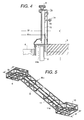
- Figure 4 is an enlarged sectional view showing one side of the balustrade along a IV-IV line of figure 1.
- Figure 5 is a perspective view which shows the main frame of the escalator shown by figure 1.
- Figure 6 is a side view showing other embodiments being equivalent to figure 3 in the present invention.
- Figure 7 is a view showing further other embodiments being equivalent to figure 6 in the present invention.
- An escalator 4 being a passenger conveyer which is installed in parallel with steps 3 to communicate a upper rank floor 1 and a lower floor 2 of a building, has a main frame 5, plurarity of foot steps 6 which are guided in the main frame 5, are connected in an endless state and circulate, a pair of balustrade 7a, 7b installed on the main frame 5 at both sides of the foot steps 6, and moving handrails 8 to respectively move around peripheries of the balustrades 7a, 7b in synchronism with the foots steps 6.
- the above stated main frame 5 is constructed with an upper horizontal part 9 and a lower horizontal level 10 formed at both edges of a longitudinal direction of the main frame 5, and an intermediate part 11 to connect both the upper horizontal part 9 and the lower horizontal part 10.
- Width dimension W0 of the intermediate part 11 is formed narrower than that W of the upper horizontal part 9 and the lower horizontal part 10.
- width dimension W0 of the intermediate part 11 is narrower, is determined based on a consideration not to make the width of the steps 3 narrower when setting the escalator 4.
- the upper horizontal part 9 and the lower horizontal part 10 should not be narrower because a driving machine or a driving mechanism for the foot step 6 and the moving handrail 8 (not shown in the figure) or a control machinery thereof is provided therein, however as an upper part getting on and off floor 12 or a lower getting on and off floor (not shown in the figure) respectively forms a flat floor with an upper floor 1 or a lower floor 2, it does not become barrier for a walker without meking it narrower.
- tops of the upper horizontal part 9 and the lower horizontal part 10 is covered with an upper part getting on and off floor 12 and a lower part getting on and off floor, and the passenger gets on and off to said foot step 6 from this place.
- These getting on and off floor has a same width dimension W3 almost the same as a width dimension W of said the upper horizontal part 9 and the lower horizontal part 10.
- These getting on and off floor has a central getting on and off floor part 12a having a width dimension W1 almost the same as a width dimension W0 of the intermediate part 11 of the main frame 5 and side getting on and off floor parts 12b, 12c having width dimension W2 at both side of the central getting on and off floor part 12a, and at least the central getting on and off floor part 12a is fixed on the top of the upper horizontal part 9 and the lower horizontal part 10 to be able to be put on and be taken off, and it is divided into plural pieces so as to be easy to be put on and be taken off.
- the escalator 4 being constituted like the above, is disposed to be approached to a wall 13 being one side in a width direction of the steps 3 is , and it Then, the balustrade 7a in opposite side of the wall 13 among pair of the balustrades 7a, 7b of the escalator 4 has a function of a wall for partitioning off the escalator 4 from the steps 3.
- balustrade 7a in the opposite side of balustrade 7a to the wall 13, a handrail 14 for a walker is arranged, and the walker utilizing steps 3 is facilitated.
- the handrail 14 for the walker in this embodiment is provided as that the length of the handrail 14 is formed to be longer than the length of the balustrade 7a, and the start or end edge of the handrail 14 for the walker is installed so as to be respectively exceed a dimension L from the start or end edge of the balustrade 7a of the passenger conveyer.
- This handrail 14 for the walker is installed outside of the width dimension W0 of the intermediate part 11 constituting the main frame 5 and inside of the width dimension W of the both of the upper horizontal part 9 and the lower horizontal part 10, thereby the width of the steps 3 offered to the walk is provided not to be reduced.
- the handrail 14 for the walker is supported through support member 16 in balustrade pillar 15 fixed on a upper chord 11a constituting the main frame 5, on the balustrade 7a as shown in figure 4, and the edge of the handrail 14 for the walker which exceeds the dimension L from the start or end edge of the balustrade 7a is supported in the main frame 5 located under the side getting on and off floor part 12c and constituting the upper horizontal part 9 as shown in figure 3.
- the waker can walh without touching the balustrade 7a and catching the handrail 14 for the walker so as to be safe.
- the waker using the steps is prevented from getting hold the moving handrail 8 of the escalator 4 side in the wrong, and the safety of the step passage facilities is improved, by let the edges of the handrail 14 for the walker respectively exceeded the dimension L from the start or end edge of the balustrade 7a. That is to say, when the start or end edge of the handrail 14 for the walker is located in the steps 3 side than the start or end edge of the balustrade 7a, the step user is going to go up and down from this side of the steps along the escalator 4 installed along the steps and along the wall, and even if after going down the steps 3, the step user is going to go along the escalator 4 and the wall.
- the handrail 14 for the walker is directly or indirectly supported on the main frame 5 entirely.
- the escalator 4 can be utilized to smoothly get on and off.
- the handrail 14 for the walker is installed over the start or end edge of the balustrade 7a along the balustrade 7a of the escalator 4.
- the handrail 14 for the walker may be constructed with a main handrail 17 for the walker being shortened than total length of the balustrade 7a so that the start or end edge thereof does not reach to the start or end edge of balustrade 7a and a supplementary handrail for a walker 18 that is installed along an extension line top of the handrail 17 for the walker, and an effect same as in the embodiment stated the above may be attained.
- One side of the supplementary handrail 18 for the waker which approaches the balustrade 7a is supported in the main frame 5 through the balustrade pillar 15 and the support member 16, and the edge being over L dimension from the start or end edge of the balustrade 7a is supported on the main frame 5, in the same way as the embodiment stated the above .
- the edge of the handrail 14 for the walker or an edge 18e of the supplementary handrail 18 for the waker to constitute the handrail 14 for the walker is protoruded a dimension L from the start or end edge of the balustrade 7a, howevere, in a case to only prevent to get hold of the moving handrail 8 of the step walker, the balustrade for the walker is installed over entire section of the balustrade 7a, that is, the edge of the handrail 14 for the walker or the edge 18e of the supplementary handrail 18 for the waker may be installed in a same location as the start or end edge of the balustrade 7a.
- the supplementary handrail for the waker 20 which one end thereof overlaps with the handrail 19 in a longitudinal direction thereof and another end thereof is located in the same location as the start or end edge of the balustrade 7a or exceeds it, may be fixed in the main frame (not illustrated in the figure) under the getting on and off floor 12.
- the edge of the handrail 14 for the walker or the supplementary handrail for the waker 18, 20 may be fixed on the upper floor 1 and the lower floor 2.
- a passenger conveyer is installed in parallel with one side of the steps in a width direction thereof, however in case of steps having a wide width, the passenger conveyer may be installed in a center of the steps in a width direction thereof, and the handrails for the walker may be installed in both sides of the passenger conveyer.
Landscapes
- Escalators And Moving Walkways (AREA)
- Steps, Ramps, And Handrails (AREA)
Abstract
Description
Claims (8)
- A step passage facilities having a passenger conveyer installed in a step passage and a handrail for a walker installed on a balustrade of said passenger conveyer, wherein
a start or an end edge of said handrail for the walker is respectively installed on a same location with a start or an end edge of said balustrade of said passenger conveyer. - A step passage facilities having a passenger conveyer installed in a step passage and a handrail for a walker installed on a balustrade of said passenger conveyer, wherein
a start or an end edge of said handrail for the walker are respectively installed at a location exceeding a start or an end edge of said balustrade of said passenger conveyer to an advance direction. - A step passage facilities installing a passenger conveyer having a handrail for a walker in a step passage, said handrail for said walker being installed on a balustrade of said passenger conveyer, wherein
said handrail for said walker has a length to exceed and a start or an end edge of said balustrade of said passenger conveyer. - A step passage facilities as defined in claim 1, 2 or 3, whereina main frame of said passenger conveyer has horizontal parts installed on both edges in longitudinal direction of said main frame and an intermediate part formed to have a narrower width than that of said horizontal parts,said balustrade is provided along said intermediate part of the said main frame,an intermediate part of said handrail for said walker is supported in said balustrade, anda start or an end edge of said handrail is supported on said horizontal part of said main frame.
- A step passage facilities as defined in claim 1, 2, 3 or 4, wherein
said handrail for said walker is installed out side of a width dimension of said intermediate part of said main frame and is installed inside of a width dimension of said horizontal part. - A step passage facilities as defined in claim 1, 2, 3, 4 or 5, wherein
said handrail for said walker has a main handrail for said walker and an Supplementary handrail for said walker connecting directly or indirectly to said start or said end edge of said main handrail for said walker. - A step passage facilities having a passenger conveyer installed in a step passage and a handrail for a walker installed on a balustrade of said passenger conveyer, wherein
said handrail for said walker is provided over entire section of said balustrade of said passenger conveyer. - A step passage facilities having a passenger conveyer installed in a step passage and a handrail for a walker installed on a side of said passenger conveyer, wherein
a start or end edge of said handrail for said walker is provided on a location to exceed entire section of said balustrade of said passenger conveyer.
Applications Claiming Priority (2)
| Application Number | Priority Date | Filing Date | Title |
|---|---|---|---|
| JP2000068613 | 2000-03-08 | ||
| JP2000068613A JP3435382B2 (en) | 2000-03-08 | 2000-03-08 | Stairway aisle equipment |
Publications (3)
| Publication Number | Publication Date |
|---|---|
| EP1134177A2 true EP1134177A2 (en) | 2001-09-19 |
| EP1134177A3 EP1134177A3 (en) | 2002-05-08 |
| EP1134177B1 EP1134177B1 (en) | 2004-09-15 |
Family
ID=18587644
Family Applications (1)
| Application Number | Title | Priority Date | Filing Date |
|---|---|---|---|
| EP20000127108 Expired - Lifetime EP1134177B1 (en) | 2000-03-08 | 2000-12-11 | Stairway facility having a passenger conveyor in parallel with a stairway |
Country Status (5)
| Country | Link |
|---|---|
| EP (1) | EP1134177B1 (en) |
| JP (1) | JP3435382B2 (en) |
| CN (1) | CN1149173C (en) |
| DE (1) | DE60013762T2 (en) |
| TW (1) | TWM245203U (en) |
Families Citing this family (3)
| Publication number | Priority date | Publication date | Assignee | Title |
|---|---|---|---|---|
| CN101899892A (en) * | 2009-05-25 | 2010-12-01 | 裘苗全 | Dual-purpose ladder for body building and emergency |
| JP5627382B2 (en) * | 2010-10-12 | 2014-11-19 | 三菱電機株式会社 | Man conveyor |
| CN112919293A (en) * | 2021-03-15 | 2021-06-08 | 北京城建设计发展集团股份有限公司 | Parallel arrangement structure of stairs and escalators of large lifting section in rail transit station |
Family Cites Families (4)
| Publication number | Priority date | Publication date | Assignee | Title |
|---|---|---|---|---|
| JP2743748B2 (en) * | 1992-12-24 | 1998-04-22 | 株式会社日立製作所 | Passenger conveyor |
| JP3435201B2 (en) * | 1993-12-27 | 2003-08-11 | 株式会社日立製作所 | Passage equipment |
| JPH1045368A (en) * | 1996-08-02 | 1998-02-17 | Inax Corp | Tile wall structure of escalator side plate |
| JP3595717B2 (en) * | 1999-03-10 | 2004-12-02 | 株式会社日立製作所 | Passage equipment |
-
2000
- 2000-03-08 JP JP2000068613A patent/JP3435382B2/en not_active Expired - Fee Related
- 2000-12-06 TW TW92217660U patent/TWM245203U/en not_active IP Right Cessation
- 2000-12-11 EP EP20000127108 patent/EP1134177B1/en not_active Expired - Lifetime
- 2000-12-11 DE DE2000613762 patent/DE60013762T2/en not_active Expired - Fee Related
- 2000-12-28 CN CNB00137785XA patent/CN1149173C/en not_active Expired - Fee Related
Also Published As
| Publication number | Publication date |
|---|---|
| DE60013762D1 (en) | 2004-10-21 |
| JP3435382B2 (en) | 2003-08-11 |
| DE60013762T2 (en) | 2005-09-29 |
| HK1037356A1 (en) | 2002-02-08 |
| CN1312214A (en) | 2001-09-12 |
| EP1134177A3 (en) | 2002-05-08 |
| TWM245203U (en) | 2004-10-01 |
| CN1149173C (en) | 2004-05-12 |
| JP2001253675A (en) | 2001-09-18 |
| EP1134177B1 (en) | 2004-09-15 |
Similar Documents
| Publication | Publication Date | Title |
|---|---|---|
| TW593115B (en) | Passenger conveyor device | |
| EP1134177A2 (en) | Step passage handrail afixed on the balustrade of a parallel running escalator | |
| EP1454869B1 (en) | Passenger conveyor | |
| JP2008013290A (en) | Passenger conveyor | |
| JP4410339B2 (en) | Passenger conveyor installation method | |
| JP3603690B2 (en) | Passenger conveyor | |
| JP3205330B2 (en) | Escalator device | |
| JP3612468B2 (en) | Stairway facility with intermediate landing | |
| JP3211437B2 (en) | Passenger conveyor | |
| JP3143818B2 (en) | Passage equipment | |
| JP2743748B2 (en) | Passenger conveyor | |
| KR19990013741U (en) | Railing arrangement structure of moving walkway | |
| JP3978510B2 (en) | Wheelchair escalator | |
| JPH0252896A (en) | Escalator | |
| JP3599620B2 (en) | Passenger conveyor | |
| JP2009091111A (en) | Passenger conveyor | |
| JP3453879B2 (en) | escalator | |
| JP3496656B2 (en) | Passage equipment and passenger conveyor for passage equipment | |
| JP2003155185A (en) | Passenger transport equipment | |
| JPH02215692A (en) | Evacuation structure of passenger conveyor | |
| JP2002338182A (en) | Passenger conveyor | |
| HK1037356B (en) | Step passage facilities having passenger conveyer in parallel with step passage | |
| JPH0724867U (en) | Parapet equipment for passenger conveyors | |
| JPH0514074U (en) | Parapet of passenger conveyor | |
| JPH05278983A (en) | Parapet of passenger conveyor |
Legal Events
| Date | Code | Title | Description |
|---|---|---|---|
| PUAI | Public reference made under article 153(3) epc to a published international application that has entered the european phase |
Free format text: ORIGINAL CODE: 0009012 |
|
| AK | Designated contracting states |
Kind code of ref document: A2 Designated state(s): AT BE CH CY DE DK ES FI FR GB GR IE IT LI LU MC NL PT SE TR |
|
| AX | Request for extension of the european patent |
Free format text: AL;LT;LV;MK;RO;SI |
|
| PUAL | Search report despatched |
Free format text: ORIGINAL CODE: 0009013 |
|
| AK | Designated contracting states |
Kind code of ref document: A3 Designated state(s): AT BE CH CY DE DK ES FI FR GB GR IE IT LI LU MC NL PT SE TR |
|
| AX | Request for extension of the european patent |
Free format text: AL;LT;LV;MK;RO;SI |
|
| 17P | Request for examination filed |
Effective date: 20021108 |
|
| AKX | Designation fees paid |
Designated state(s): DE FR |
|
| 17Q | First examination report despatched |
Effective date: 20030623 |
|
| GRAP | Despatch of communication of intention to grant a patent |
Free format text: ORIGINAL CODE: EPIDOSNIGR1 |
|
| RTI1 | Title (correction) |
Free format text: STAIRWAY FACILITY HAVING A PASSENGER CONVEYOR IN PARALLEL WITH A STAIRWAY |
|
| GRAS | Grant fee paid |
Free format text: ORIGINAL CODE: EPIDOSNIGR3 |
|
| GRAA | (expected) grant |
Free format text: ORIGINAL CODE: 0009210 |
|
| AK | Designated contracting states |
Kind code of ref document: B1 Designated state(s): DE FR |
|
| REG | Reference to a national code |
Ref country code: IE Ref legal event code: FG4D |
|
| REF | Corresponds to: |
Ref document number: 60013762 Country of ref document: DE Date of ref document: 20041021 Kind code of ref document: P |
|
| PLBE | No opposition filed within time limit |
Free format text: ORIGINAL CODE: 0009261 |
|
| STAA | Information on the status of an ep patent application or granted ep patent |
Free format text: STATUS: NO OPPOSITION FILED WITHIN TIME LIMIT |
|
| ET | Fr: translation filed | ||
| 26N | No opposition filed |
Effective date: 20050616 |
|
| PGFP | Annual fee paid to national office [announced via postgrant information from national office to epo] |
Ref country code: FR Payment date: 20051123 Year of fee payment: 6 |
|
| PGFP | Annual fee paid to national office [announced via postgrant information from national office to epo] |
Ref country code: DE Payment date: 20051202 Year of fee payment: 6 |
|
| PG25 | Lapsed in a contracting state [announced via postgrant information from national office to epo] |
Ref country code: DE Free format text: LAPSE BECAUSE OF NON-PAYMENT OF DUE FEES Effective date: 20070703 |
|
| REG | Reference to a national code |
Ref country code: FR Ref legal event code: ST Effective date: 20070831 |
|
| PG25 | Lapsed in a contracting state [announced via postgrant information from national office to epo] |
Ref country code: FR Free format text: LAPSE BECAUSE OF NON-PAYMENT OF DUE FEES Effective date: 20070102 |