EP1133050B1 - Method of estimating a rotor position of synchronous motor, method of controlling synchronous motor with no position sensor and a controller of synchronous motor - Google Patents
Method of estimating a rotor position of synchronous motor, method of controlling synchronous motor with no position sensor and a controller of synchronous motor Download PDFInfo
- Publication number
- EP1133050B1 EP1133050B1 EP00118260A EP00118260A EP1133050B1 EP 1133050 B1 EP1133050 B1 EP 1133050B1 EP 00118260 A EP00118260 A EP 00118260A EP 00118260 A EP00118260 A EP 00118260A EP 1133050 B1 EP1133050 B1 EP 1133050B1
- Authority
- EP
- European Patent Office
- Prior art keywords
- motor
- axis
- voltage
- phase
- current
- Prior art date
- Legal status (The legal status is an assumption and is not a legal conclusion. Google has not performed a legal analysis and makes no representation as to the accuracy of the status listed.)
- Expired - Lifetime
Links
- 238000000034 method Methods 0.000 title claims description 50
- 230000001360 synchronised effect Effects 0.000 title claims description 50
- 239000013598 vector Substances 0.000 claims description 55
- 238000004804 winding Methods 0.000 claims description 16
- 230000007423 decrease Effects 0.000 claims description 8
- 230000003247 decreasing effect Effects 0.000 claims description 6
- 238000010586 diagram Methods 0.000 description 20
- 230000004907 flux Effects 0.000 description 12
- 238000001514 detection method Methods 0.000 description 10
- 238000009795 derivation Methods 0.000 description 5
- 238000006243 chemical reaction Methods 0.000 description 4
- 238000010276 construction Methods 0.000 description 4
- 238000004364 calculation method Methods 0.000 description 3
- 230000006698 induction Effects 0.000 description 2
- 239000003990 capacitor Substances 0.000 description 1
- 230000001419 dependent effect Effects 0.000 description 1
- 230000008030 elimination Effects 0.000 description 1
- 238000003379 elimination reaction Methods 0.000 description 1
- 238000011156 evaluation Methods 0.000 description 1
- 238000009499 grossing Methods 0.000 description 1
- 239000004065 semiconductor Substances 0.000 description 1
Images





Classifications
-
- H—ELECTRICITY
- H02—GENERATION; CONVERSION OR DISTRIBUTION OF ELECTRIC POWER
- H02P—CONTROL OR REGULATION OF ELECTRIC MOTORS, ELECTRIC GENERATORS OR DYNAMO-ELECTRIC CONVERTERS; CONTROLLING TRANSFORMERS, REACTORS OR CHOKE COILS
- H02P6/00—Arrangements for controlling synchronous motors or other dynamo-electric motors using electronic commutation dependent on the rotor position; Electronic commutators therefor
- H02P6/14—Electronic commutators
- H02P6/16—Circuit arrangements for detecting position
- H02P6/18—Circuit arrangements for detecting position without separate position detecting elements
-
- H—ELECTRICITY
- H02—GENERATION; CONVERSION OR DISTRIBUTION OF ELECTRIC POWER
- H02P—CONTROL OR REGULATION OF ELECTRIC MOTORS, ELECTRIC GENERATORS OR DYNAMO-ELECTRIC CONVERTERS; CONTROLLING TRANSFORMERS, REACTORS OR CHOKE COILS
- H02P21/00—Arrangements or methods for the control of electric machines by vector control, e.g. by control of field orientation
- H02P21/14—Estimation or adaptation of machine parameters, e.g. flux, current or voltage
- H02P21/18—Estimation of position or speed
-
- H—ELECTRICITY
- H02—GENERATION; CONVERSION OR DISTRIBUTION OF ELECTRIC POWER
- H02P—CONTROL OR REGULATION OF ELECTRIC MOTORS, ELECTRIC GENERATORS OR DYNAMO-ELECTRIC CONVERTERS; CONTROLLING TRANSFORMERS, REACTORS OR CHOKE COILS
- H02P2207/00—Indexing scheme relating to controlling arrangements characterised by the type of motor
- H02P2207/05—Synchronous machines, e.g. with permanent magnets or DC excitation
Definitions
- the present invention relates to synchronous motor control methods and more particularly, to a method of estimating a rotor position of a synchronous motor having saliency and method and system of controlling the synchronous motor with no position sensor (without resort to a position sensor).
- the method for use in the conventional position-sensorless technique is classified into two main methods of which one utilizes saliency that makes the winding inductance differ with rotation positions and the other utilizes a voltage of speed electromotive force induced in the motor winding.
- one utilizes saliency that makes the winding inductance differ with rotation positions
- the other utilizes a voltage of speed electromotive force induced in the motor winding.
- no speed electromotive force is generated during stopping and low-speed operation and hence position estimation is difficult to achieve but during medium/high-speed operation
- the latter method can advantageously be applicable to both the salient type and the non-salient type.
- JP-A-8-308286 there is also available a technique disclosed in JP-A-8-308286 (prior art 2).
- this technique in relation to a d-q real rotary coordinate system having d axis representing positions in the direction of magnetic flux of the permanent magnet rotor and q axis 90° leading the d axis in the rotary direction, a dc-qc rotary coordinate system having dc axis representing virtual rotary positions from the control viewpoint and qc axis 90° leading the dc axis in the rotary direction is defined from the control viewpoint.
- Estimation of a real rotary position takes advantage of the fact that when a difference between d axis current estimated on the basis of a motor model derived from a voltage/current equation on the d-q rotary coordinates and dc axis current on the control axis is calculated, this difference is proportional to an axis shift ⁇ ⁇ of virtual rotary position.
- an expression for estimating vector components of the expanded induced voltage is derived pursuant to the known minimum dimension observer method and a rotor position of the motor is determined from an estimated expanded induced voltage.
- the derived estimation expression for the expanded induced voltage uses winding resistance r, inductances Ld and Lq as motor constants and performs an operation by using values of voltage and current on the stator coordinates and an estimated speed of the motor.
- an intermediate variable constructed of the sum of components related to the expanded induced voltage and the current is introduced so that the expression may be reduced so as to estimate the intermediate variable without using the current differential value.
- the prior art 1 cannot be applied to the salient-pole machine. This is because in the salient-pole machine, the winding inductance changes with the rotation position and therefore, unless the rotor position is known, the inductance cannot be determined and the magnitude of a voltage drop due to the inductance cannot be determined.
- a current value on the dc-qc control rotary coordinate system representing the virtual rotary axis is estimated by using the motor model on the d-q rotary coordinates. Accordingly, when the virtual rotary axis shifts from the real rotary position, the position cannot be estimated correctly. Besides, an approximation of sin ⁇ ⁇ ⁇ ⁇ ⁇ is carried out when deriving an operation expression of axis shift ⁇ . Consequently, when an actual axis shift is large, the axis shift ⁇ ⁇ cannot be operated correctly. Therefore, the prior art 2 has a disadvantage that it is unsuited for applications in which the motor load changes abruptly or an abrupt accelerating /decelerating operation takes place.
- the prior art 3 is based on the stator coordinates ( ⁇ ⁇ axis) as described above and hence, the expanded induced voltage about to be estimated is of an AC (alternating current) quantity. Consequently, during high-speed operation of the motor, the expanded induced voltage changes at a higher rate than the speed of estimation pursuant to the estimation expression based on the minimum dimension observer, giving rise to a problem that the rotor position cannot be estimated correctly.
- the estimation expression not using a differential of observed current is employed.
- the differential of the observed current on the stator coordinates is mainly related to a voltage drop due to inductance, demonstrating that the technique of prior art 3 determines the position without using a voltage drop component due to inductance. Therefore, the estimation expression based on the minimum dimension observer is said to estimate the expanded induced voltage and the voltage drop component due to inductance indistinctively.
- the voltage drop component increases in proportion to current and accordingly, when a relatively large current flows, the voltage drop component becomes larger than the expanded induced voltage, thus raising a problem that the accuracy of position estimation based on the observer is degraded.
- the inductance value is very liable to change owing the flux saturation during current increase.
- the techniques of prior arts 2 and 3 require two parameters Ld and Lq of inductance in the motor winding. Accordingly, the rotor position must be estimated correctly without being affected by changes in the two inductance parameters Ld and Lq and because of the necessity of correcting the two parameters, the construction becomes complicated.
- the present invention contemplates elimination of the above conventional problems and it is an object of the invention to provide a rotor position estimating method which can correctly estimate the rotor position of a synchronous motor having saliency from the phase of an induced voltage and method and apparatus of controlling the synchronous motor without using a position sensor which can be applied with the estimation method to stably perform a high-speed operation or abrupt load change and abrupt accelerating/decelerating operation.
- This object is achieved by a method according to claim 1 and a system according to claim 6.
- avoidance of the use of such unobservable quantities and approximate value as in the prior arts 2 and 3 is considered to improve the accuracy of estimation of the rotor position of a synchronous motor having saliency (simply termed a salient-pole machine) from the phase of a voltage induced in the motor.
- a salient-pole machine When trying to determine an induced voltage on the basis of the voltage equation of the salient-pole machine, a voltage drop due to an inductance of motor winding depends on the rotor position and therefore cannot be observed without resort to a position sensor or in a position-sensorless fashion.
- the intended object can be attained if the phase or an induced voltage can be estimated correctly even with a failure to correctly estimate the magnitude of the induced voltage.
- a concept of virtual voltage drop by which a voltage drop due to an inductance does not depend on the rotor position is introduced and the virtual voltage drop is used to determine induced voltage while finding the vector relation of the virtual voltage drop in the voltage equation that does not impair the phase of an original induced voltage.
- the voltage drop due to inductance is determined from a virtual voltage drop representing a quantity that uses a predetermined value as the inductance and is dephased by a predetermined amount from a motor current (Im). Then, from the estimated induced voltage, a phase of the induced voltage is calculated to estimate the rotor position.
- a vector of the virtual voltage drop is so derived as to prevent the phase of the induced voltage from changing and as to permit a change of the induced voltage to be computed.
- the inductance constant of the synchronous motor having saliency is defined by Ld and Lq.
- Inductance constant Ld is a parameter indicative of the relation between d axis current and magnetic flux ⁇ d on the rotary coordinates (d-q axis) and in the case of permanent magnet type, the direction of flux generated by the magnet is the same as that of the flux ⁇ d due to the d axis current.
- Inductance constant Lq is a parameter indicative of the relation between q axis current and flux ⁇ q and in the case of permanent magnet type, flux generated by the magnet is orthogonal to the flux ⁇ q due to the q axis current.
- the inductance voltage drop has a vector that 90° leading the motor current (Im) and uses the inductance Lq representing a motor electrical constant of the salient-pole machine as the aforementioned predetermined value. Then, the inductance voltage drop is determined from the product of the Lq, the magnitude of the observable motor current and an observable frequency ( ⁇ 1) of motor applied voltage or motor speed command value ( ⁇ r*). Through this, the inductance voltage drop not causing the phase of induced voltage to change can be calculated on the basis of the observable quantities and estimation of the phase of induced voltage can be simplified.
- phase of induced voltage that is, the rotor position can be estimated accurately on the basis of the observable quantities.
- the aforementioned virtual voltage drop is an operation model using the constants for the inductance but since the vector relation is introduced in which the use of the constants does not reflect upon the phase of induced voltage, phase of induced voltage determined in the present invention does not have a value based on the approximation (sin ⁇ ⁇ ⁇ ⁇ ⁇ ) in the prior art but can have accurate values over a wide range.
- the frequency of motor applied voltage is controlled such that the rotation speed of the virtual rotor position is decreased when the axis shift angle has a value indicating that the virtual rotor position leads the actual rotor position in the rotation direction of the rotor and the rotation speed of the virtual rotor position is increased when lagging is indicated.
- a torque command value for the motor is so controlled as to increase the rotation speed of the actual rotor position but to decrease the rotation speed of the actual rotor position when having a value indicating that the virtual rotor position lags the actual rotor position.
- the axis shift ⁇ ⁇ between the control axis and the real axis is determined directly from the phase of the induced voltage of motor and hence, even when the axis shift increases owing to an abrupt change in load, stable and highly accurate control can be ensured.
- an error compensation value of the axis shift angle is set and the frequency of the motor applied voltage or the torque command value is so controlled as to render the difference between the axis shift angle and the error compensation value zero. Further, setting of the error compensation value is so adjusted as to minimize the motor current under a condition that the rotation speed of the motor and the load on the motor are constant. This can eliminate the influence of ane error of set parameter to realize more accurate control.
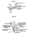
- FIG. 2 there is illustrated an analytical model of a permanent magnet synchronous motor, indicating a stator winding of U phase, V phase and W phase and a permanent magnet rotor.
- the rotation angle in the figure is indicated by an electrical angle of AC voltage driving the motor.
- d axis is established in the flux direction of the permanent magnet rotor and dc axis is established to indicate the virtual rotor position from the control viewpoint.
- q axis 90° leading the d axis is set up and qc axis 90° leading the dc axis is set up.
- the rotor coordinates represent a coordinate system having coordinate axes of d axis and q axis.
- d-q coordinate axis will be simply referred to as real axis.
- the virtual rotor coordinates represent a coordinate system having coordinate axes of dc axis and qc axis.
- dc-qc coordinate axis will be simply called control axis.
- the real axis is rotating at a rotary speed of ⁇ r.
- the control axis is also rotating at a rotary speed of ⁇ 1.
- ⁇ 1 represents the rotary speed of the control axis but when the motor is driven externally, it corresponds to a frequency of motor applied voltage.
- the phase of d axis is indicated by ⁇ d in relation to a reference of the U phase winding axis of the stator.
- the phase of dc axis is indicated by ⁇ dc.
- the polarity of phase is defined as positive when the rotation direction of the rotary coordinate axis in Fig. 2 is counterclockwise.
- An axis shift ⁇ ⁇ between the real axis and the control axis is defined by equation (1).
- ⁇ ⁇ dc - ⁇ d
- Vd and Vq are d-axis and q-axis components of motor applied voltage V1
- Id and Iq are d-axis and q-axis components of motor current Im.
- the Vd, Vq, Id and Iq are voltage and current values on the real axis and therefore, in the case of control without resort to position sensor in which positions on the real axis are unknown, they are unobservable quantities.
- the fourth term on the right side in equation (2), KE ⁇ r represents speed electromotive force generated by rotation of the motor, that is, the magnitude of an induced voltage.
- equation (2) is reduced to an equation on the virtual rotor coordinates. Since the axis shift between the real axis and the control axis is ⁇ ⁇ , voltage and current vectors on the real axis can be expressed by equation (3) in accordance with observable voltages Vdc and Vqc and current values Idc and Iqc on the control axis.
- equation (4) that expresses a voltage equation on the virtual rotor coordinates.
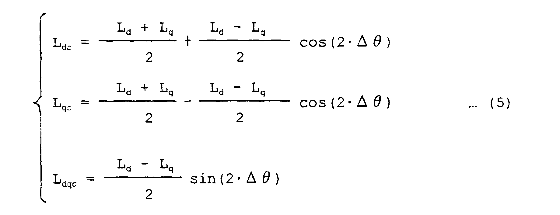
- inductances Ldc, Lqc and Ldquc are given by equation (5).
- FIG. 3 there is illustrated a vector diagram showing the relation between voltages at different portions in the permanent magnet motor having saliency.
- Motor applied voltage V1 is given by the sum of an induced voltage representing speed electromotive force, a vector Vr of a voltage drop across the resistor and a vector VL of a voltage drop across the inductance.
- motor currents Id and Iq do not change and are regarded as constant values. This means that a differential term of the third term on the right side in equation (2) or differential terms of the third and fourth terms on the right side in equation (4) are neglected.
- the estimation of magnetic pole position based on speed electromotive force takes advantage of the fact that the phase of the induced voltage of motor occurs in the q axis direction 90° leading the flux axis. Accordingly, by estimating components of the induced voltage vector on the dc-qc coordinates representing the control axis and determining an angle between the vector and the qc axis as shown in Fig. 3, the axis shift ⁇ ⁇ between the control axis and the real axis can be determined. Since the induced voltage term cannot be observed externally, it is estimated usually from an observable quantity.
- Various methods for estimation have been proposed but essentially, an estimated induced voltage is determined by subtracting the voltage drop vectors Vr and VL across the resistance and inductance from the motor applied voltage V1.
- the voltage drop Vr across the resistance can be computed from an observable quantity.
- the Vr is in phase with the motor current Im and its magnitude is r times the motor current. This relation stands regardless of the coordinate system and in the vector diagram, the Vr and Im are indicated in the same direction. Accordingly, the voltage drop Vr across the resistance can be computed from observable current detection values Idc and Iqc on the dc-qc coordinates.
- the voltage drop VL across the inductance cannot be computed if the position of the real axis is unknown.
- the VL is a vector having, on the real axis, a component of - ⁇ 1 ⁇ Lq ⁇ Iq in the d axis direction and a component of ⁇ 1 ⁇ Ld ⁇ Id in the q axis direction and for_determination of the VL, current values Id and Iq on the real axis are necessary. But, since the current values Id and Iq on the real axis are unobservable, the voltage drop VL across the inductance cannot be computed.
- the second, third and fourth terms on the right side indicate the voltage drop VL, including the inductance parameters Ldc, Lqc and Ldqc and therefore, the VL cannot be computed unless the value of axis shift ⁇ ⁇ is determined. Since, in the control without resort to position sensor, ⁇ cannot be determined, the VL cannot be computed. For example, in the technique of prior art 2, an approximate value of VL is computed by using the inductance value when the axis shift ⁇ ⁇ is zero. But as the axis shift ⁇ ⁇ deviates from the vicinity of zero, the approximation error increases, giving rise to a failure to correctly estimate the induced voltage phase.
- the concept of virtual voltage drop is admitted to the voltage drop due to the inductance.
- the virtual voltage drop is a kind of operation model but to prevent the accuracy of the phase of the target induced voltage from being degraded even when operation is conducted by using this operation model, the virtual voltage drop is introduced on condition that (1) the virtual voltage drop VL' can be computed from an observable current quantity, (2) to meet (1) above, the VL' is constructed of a component that is dephased from the current by a predetermined amount, a component that is dephased from the current differential value by a predetermined amount or the sum of the above two components, and (3) the vector relation is held such that the phase of a vector (assumptively, called a virtual induced voltage) obtained by subtracting voltage drop Vr across the resistance and virtual voltage drop VL' from the motor applied voltage V1 (assumptively, called virtual induced voltage) is in phase with the original motor induced voltage.
- a virtual induced voltage a vector (assumptively, called a virtual
- the virtual voltage drop VL' is constructed of the sum of a component 90° leading the current phase and a component in phase with the current differential.
- the phase of a vector obtained by subtracting the voltage drop Vr across the resistance and the virtual voltage drop VL' coincides with the phase of the original induced voltage.
- only the component 90° leading the current phase may be used as will be described later.
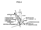
- FIG. 4 A voltage equation relation similar to that in Fig. 3 is illustrated in a vector diagram of Fig. 4 by using the virtual voltage drop VL'.
- the inductance value for d axis differs from that for q axis but in the virtual voltage drop VL' in Fig. 4, both the inductance values have the same value to satisfy condition (2).
- the inductance value of the q axis component in phase with the induced voltage is changed in the VL'.
- the phase of VL' can be determined as a phase 90° leading the current Im. Since the VL and VL' differ from each other in the q axis direction component, the induced voltage indicated by blanked arrow in Fig. 4 does not differ from that in Fig. 3 in phase but differs in only magnitude. In other words, calculating the voltage drop due to inductance through the use of the constant Lq does not impair information about the phase of the induced voltage. It will be appreciated that the sum of the magnitude of the induced voltage and that of the inductance voltage drop in phase with the induced voltage is the same for Figs. 3 and 4.
- Two components of the virtual voltage drop VL' in Fig. 4 are indicated by unobservable values on the real axis to facilitate comparison with Fig. 3.
- the virtual voltage drop VL' in Fig. 4 is indicated by observable values on the control axis. More specifically, in Fig. 5, the virtual voltage drop VL' is indicated by components obtained by multiplying each of the observable current values Idc and Idq by Lq ⁇ 1.
- Equation (2) expresses the voltage equation on the real axis and the second and third terms on the right side indicate the voltage drop VL across the inductance.
- equation (6) the second term on the right side in equation (2) is divided into a component 90° leading the current phase and an adjusting component.
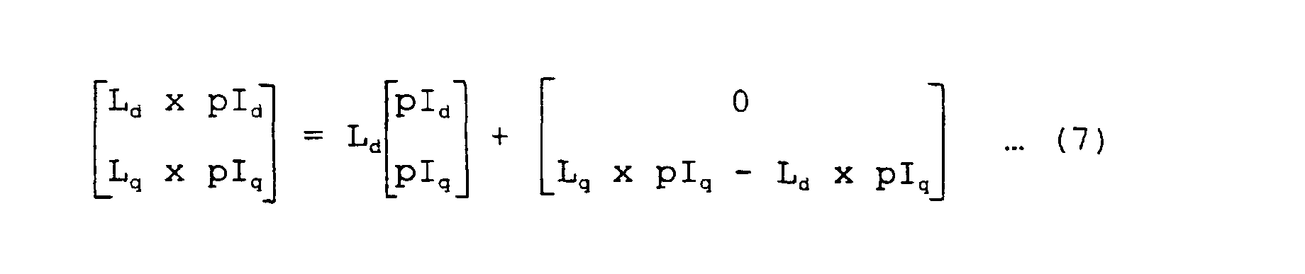
- equation (7) the third term on the right side in equation (2) is divided into a component in phase with the differential quantity of current and an adjusting component.
- the first term on the right side in equations (6) and (7) can be said to indicate a voltage drop determined on the assumption that values of inductance differing for d and q axes owing to the saliency are rendered to be constant. But, the inductance value used for the d axis component in the vectors on the left side in equations (6) and (7) is rendered to be constant. This ensures that the adjusting component in the second term on the right side in equations (6) and (7) can have a value on the q axis equal to the component of the induced voltage.
- the virtual voltage drop across the inductance is a voltage drop computed as below.
- the term proportional to rotation speed ⁇ 1 is calculated by using the inductance Lq.
- the term proportional to current changes dId/dt and dIq/dt are calculated by using the inductance Ld.
- equations (6) and (7) are substituted to equation (2), so that the voltage equation of the salient-pole machine on the real axis when the virtual voltage drop is used can be expressed by equation (9).
- the first to third terms on the right side in equation (9) indicate a voltage drop across the resistance and a virtual voltage drop across the inductance.
- the fourth term on the right side in equation (9) can be considered as an induced voltage component when the virtual voltage drop is used.
- This induced voltage differs, in magnitude, from the induced voltage in equation (2) but its component is trapped on the q axis and its d axis component is zero, demonstrating the former voltage is quite in phase with the latter voltage.
- kE ⁇ ⁇ r represents speed electromotive force generated by the permanent magnet field
- ⁇ 1 ⁇ (Ld - Lq) Id represents an induced voltage component related to reluctance torque
- (Lq - Ld) pIq represents an induced voltage due to a change in q axis current.
- Equation (9) is reduced to a voltage equation on the control axis. Firstly, equation (3) is substituted to equation (9) and there results equation (10).
- Equation (10) is reduced, so that the voltage equation of the salient-pole machine on the control axis when the virtual voltage drop is used can eventually be expressed by equation (11).
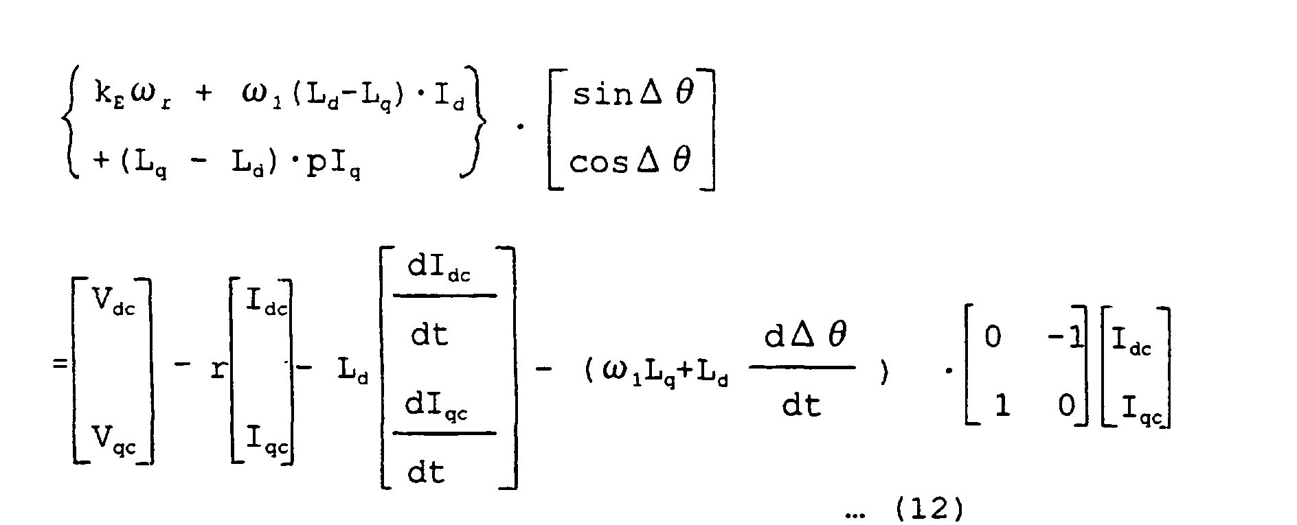
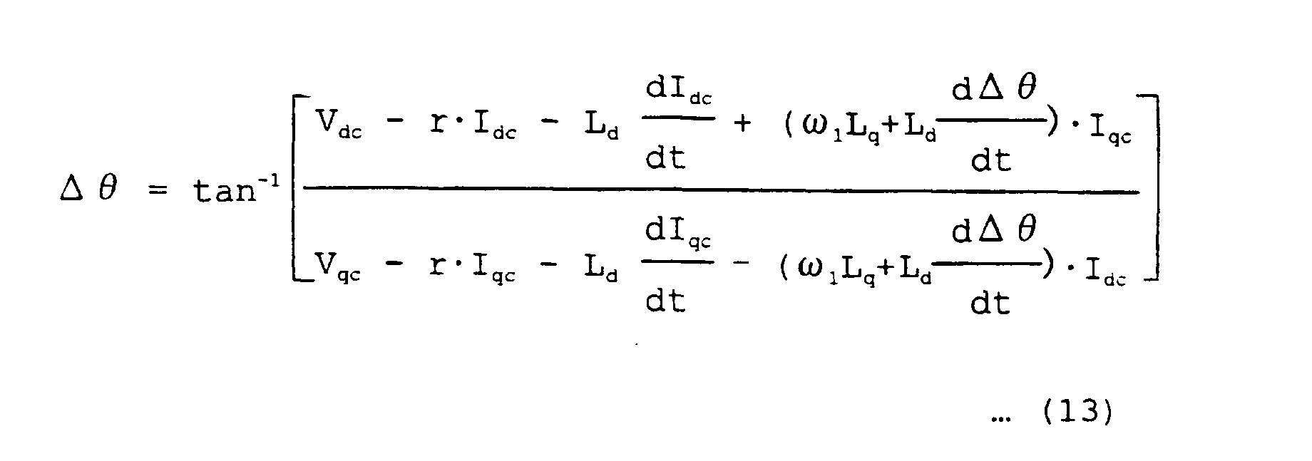
- Equation (11) An equation for deriving ⁇ is derived from equation (11). Firstly, induced voltage terms in equation (11) are put together to obtain equation (12), from which equation (13) indicative of axis shift ⁇ between the control axis and the real axis is obtained.
- equation 13 indicative of the axis shift ⁇ ⁇ between the control axis and the real axis can be obtained through the voltage equation using the virtual voltage drop.
- equation (13) stands in any operation state. For example, even in the case where the control axis and the real axis rotate asynchronously with each other, this equation stands.
- the phase angle of the induced voltage in the salient -pole machine that is, the axis shift angle ⁇ can be estimated from the observable values without depending on the position of the control axis and therefore, the rotor position can be estimated without resort to position sensor in accordance with teachings of the invention.
- the control without resort to position sensor in the salient -pole machine musing ⁇ stable control free from step-out can be implemented even in a high-speed operation at several of ten thousands of rpm and an operation in which a large axis shift occurs, for example, abrupt load change operation or abrupt accelerating/decelerating operation.
- differentials of currents Idc and Iqc converted to values on the rotary coordinate system represent a change in magnitude Im (peak value) of motor current and a change in phase of the motor current.
- iu Im ⁇ cos ( ⁇ dc + ⁇ /2 + ⁇ ) c)
- iw Im ⁇ cos ( ⁇ dc - 4 ⁇ /3 + ⁇ /2 + ⁇ c) to phase currents representing detection currents to equation (24) to be described later and by differentiating Idc and Iqc (where ⁇ c represents the phase of current).
- equation (17) the necessary parameter of inductance is Lq alone and the voltage relation is identical to the vector diagram of Fig. 5.
- the number of parameters used in the estimation equation be as small as possible. Accordingly, the method of estimating the axis shift ⁇ ⁇ by using equation (17) is superior to the prior arts 2 and 3 from the standpoint of robustness.
- equation (17) is derived from the vector relation indicating that the phase of VL' 90° leads the motor current Im and the phase of the induced voltage can be estimated through simplified calculation.
- a vector diagram therein is illustrated on the same condition as that for Figs. 3 and 4 while being referenced to the current axis.
- the phase of current axis as viewed from the qc axis is indicated by ⁇ c and the phase of motor applied voltage V1 as viewed from the current axis is ⁇ v.
- the phase of current axis as viewed from the q axis is ⁇ m.
- a relation of ⁇ m ⁇ c + ⁇ ⁇ stands between ⁇ m and ⁇ c. It will be appreciated that ⁇ c and ⁇ v are observable quantities but ⁇ m is an unobservable quantity.
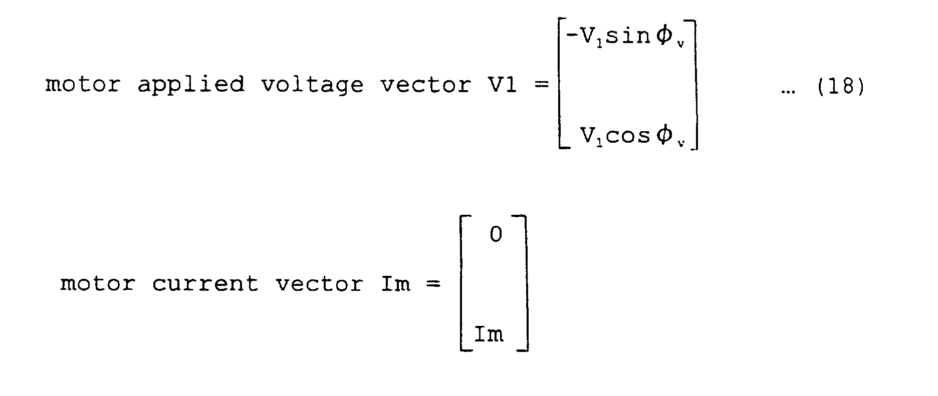
- the vector quantity in equation (18) indicates a component orthogonal to the current direction and a component in the same direction as the current direction.
- voltage V1 has a voltage component of -V1 ⁇ sin ⁇ v orthogonal to current and a voltage component of V1 ⁇ cos ⁇ v in the same direction as the current direction.
- the current has an orthogonal component that is zero and a component in the same direction that has a magnitude of Im.
- voltage drop Vr across the resistance is in phase with the current, having a component of zero orthogonal to the current and a voltage component of r ⁇ Im in the same direction as the current.
- Virtual voltage drop VL' across the inductance 90° leads the current, having a component of "- Lq ⁇ ⁇ 1 ⁇ Im" orthogonal to the current and a voltage component of zero in the same direction as the current.
- Equation (19) is substituted to equation (9) indicative of the voltage eaquation of the salient-pole machine on the real axis when the virtual voltage drop is used and there results equation (20).
- the fourth term on the right side in equation (20) contains phase information ⁇ m of induced voltage observed on the current axis.
- the fourth term on the right side is arranged to solve equation (20) for ⁇ m, thus obtaining equation (21).
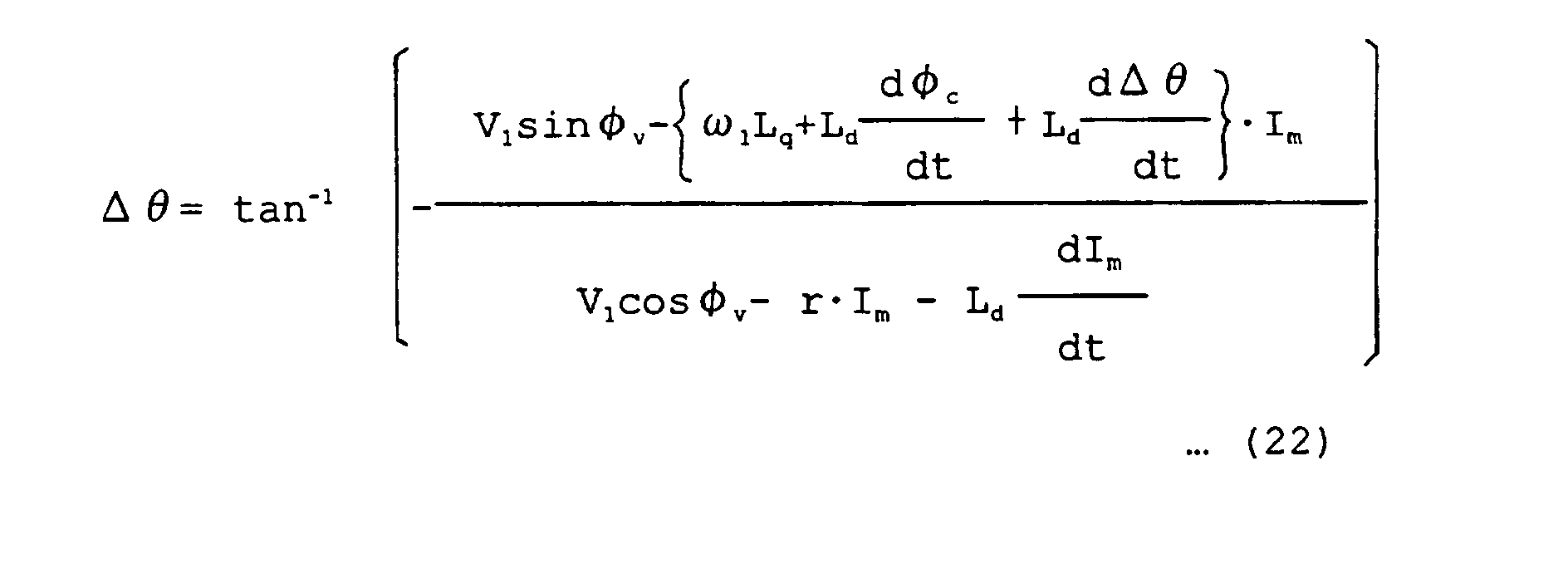
- equation (23) the axis shift angle ⁇ of the salient-pole machine can be estimated correctly from the observable values independently of the position of the control axis and therefore, the rotor position can be estimated without resort to position sensor in accordance with the invention.
- equation (23) needs only Lq as the parameter of inductance and so high robustness can also be ensured.
- the invention has been described by making reference to the case where the rotation direction of the motor rotor is forward but in the case of inverse or backward rotation direction, by considering that the direction of speed electromotive force is changed from that during forward operation and the sign of the denominator and numerator of the tangent inverse function for determining the axis shift ⁇ is changed, the axis shift ⁇ ⁇ can be determined similarly.
- the axis shift ⁇ ⁇ can be estimated from the control system by using the observable quantities.
- the permanent magnet synchronous motor is controlled without resort to position sensor in accordance with a method to be described below.
- frequency ⁇ 1 of an AC voltage applied to the motor is modified on the basis of the thus obtained estimation value of axis shift ⁇ ⁇ such that ⁇ becomes zero.
- the virtual rotary axis can be so controlled as to follow the rotor axis of the motor.
- a torque command value of the motor is modified on the basis of the thus obtained estimated value of axis shift ⁇ such that ⁇ becomes zero.
- the rotor axis of the motor can be so controlled as to follow rotation of the control axis.
- the estimation equation of axis shift E ⁇ expressed by the aforementioned equation (16), (17) or (23) can estimate ⁇ ⁇ correctly when the used parameters coincide with the actual values.
- the parameter set value contains an error and deviates from the actual value.
- an error in the estimated value of axis shift ⁇ ⁇ takes place owing to the parameter error.
- the parameter values necessary for estimating the axis shift ⁇ ⁇ are resistance r and inductance Lq.
- the virtual voltage drop VL' in Fig. 4 increases, with the result that the phase of the estimated induced voltage lags a true value of the induced voltage indicated by white blank arrow.
- the voltage drop Vr in Fig. 4 increases, so that the phase of the estimated induced voltage leads a true value of the induced voltage indicated by white blank arrow.
- the influence of the parameter error occurs in the form of a steady error in the estimated value of axis shift ⁇ ⁇ .
- a plurality of parameter errors affect each other to determine an eventual error in axis shift ⁇ .
- the phase of the control axis cannot coincide with the real axis and a steady axis shift ⁇ e remains. Under this condition, a current conforming to the command value does not flow on the real axis and a current component related to torque generation decreases. As a result, generated torque decreases to cause the speed of rotor to decrease. At that time, the control system without resort to position sensor operates to increase the motor current so as to prevent the speed from decreasing. Eventually, when the steady axis shift ⁇ ⁇ e occurs, the motor current increases.
- an axis shift error compensation value ⁇ ⁇ * is introduced and frequency ⁇ 1 of an AC voltage applied to the motor is modified such that ⁇ ⁇ * - ⁇ ⁇ becomes zero.
- the torque command value of the motor is modified such that ⁇ ⁇ * - ⁇ ⁇ becomes zero.
- An initial value of zero is substituted to the axis shift error compensation value ⁇ ⁇ * and the ⁇ ⁇ * is changed slightly to minimize the motor current under a condition that the rotation speed and load of the motor are constant and remain unchangeable.
- the error compensation value ⁇ ⁇ * can eventually approach, as closely as possible, the steady error ⁇ ⁇ e in the axis shift estimation, thereby alleviating the influence of the estimation error ⁇ ⁇ e.
- the phase of the induced voltage of the salient-pole synchronous motor can be estimated from observable values independently of the rotor position and therefore, the rotor position can be acquired with high accuracy without resort to position sensor to advantage.
- the influence of the parameter error contained in the operation result of axis shift ⁇ ⁇ can be compensated and therefore, an excellent position-sensorless system of synchronous motor that can be freed from step-out even when the parameter error is large can be provided.
- FIG. 1 the whole of a control system for implementing control of a synchronous motor without resort to position sensor according to an embodiment of the invention is constructed as shown therein.
- a power supply 11 generates a DC voltage Edc and charges a smoothing capacitor 12.
- the DC voltage Edc is converted by an inverter 13 into a three-phase alternating current of variable voltage and variable frequency which in turn is applied to a synchronous motor 2.
- a voltage detector 31 detects the DC voltage Edc necessary for controlling a voltage applied to the motor.
- a motor current detector detects a motor current necessary for position-sensorless control (control without resort to position sensor).
- a coordinate converter 41 responds to motor currents iu and iw detected by the motor current detector 32 to perform coordinate conversion for these currents on the basis of a phase ⁇ dc of a virtual rotor position dc axis so as to deliver dc axis current Idc and qc axis current Iqc on a virtual rotary coordinates dc-qc coordinate system set up from the control viewpoint.
- the currents Idc and Iqc are observable values (observation values) converted from the detected motor currents iu and iw and will be hereinafter called observation currents.
- the observation current Idc is compared with a d axis current command value Idc* delivered out of a current command generator 52 to compute a current error.
- a d axis current controller 42d responds to the current error to control the Idc to cause it to follow the command value.
- the observation current Iqc is compared with a current command value Iqc* delivered out of the current command generator 52 to calculate a current error.
- a q axis current controller 42q responds to the current error to control the Iqc to cause it to follow the command value.
- a current feed-forward compensator 43 is a feed- forward compensation device used to improve the current responsibility and to prevent interference between the d axis and q axis current control systems. Signals delivered out of the d axis current controller 42d, q axis current controller 42q and current feed-forward compensator unit 43 are used for computation of d axis voltage command Vdc* and q axis voltage command Vqc*.
- an inverse converter 44 performs inverse conversion on the basis of the phase ⁇ dc of the virtual rotor position dc axis to prepare three-phase voltage commands Vu*, Vv* and Vw * .
- a pulse width modulator 45 prepares a drive signal subjected to well-known pulse width modulation (PWM) and the drive signal controls semiconductor switching elements of the inverter 13 through a drive circuit.
- PWM pulse width modulation
- a speed controller 51 Responsive to a speed command ⁇ r * and an estimation speed ⁇ r_det, a speed controller 51 prepares a torque command ⁇ *. From a value of the torque command ⁇ *, a current command generator 52 prepares the d axis current command Idc * and q axis current command Iqc * .
- the estimated speed ⁇ r_det is obtained by removing a high-frequency change component from an inverter output frequency ⁇ 1 representing a rotation speed of the control axis and corresponds to a detection speed in a control system having a sensor.
- the inverter output frequency ⁇ 1 is a frequency of motor applied voltage and by integrating ⁇ 1, the rotor position (virtual rotor position) ⁇ dc on the control axis can be obtained.
- the components50 to 52 are merged so as to be called a current command generator and the components 42d, 42q, 43 to 44 and 53 to 55 are merged so as to be called a voltage command operating unit.
- an induced voltage/axis shift estimation operating unit 61 featuring the present embodiment estimates an induced voltage of the synchronous motor 2 from values of the voltage commands Vdc* and Vqc*, the detection currents Idc and Iqc and the speed command ⁇ r* serving as rotation speed information. Then, an axis shift estimation value ⁇ ⁇ is computed from the phase of the estimated induced voltage and is delivered. Further, the magnitude
- an axis error compensator 7 prepares a compensation quantity ⁇ * for compensating the influence of the above-described parameter error.
- a speed phase estimating unit 62 determines a frequency ⁇ 1 of the motor applied voltage from the axis shift ⁇ ⁇ and the axis shift error compensating value ⁇ ⁇ * delivered out of the axis shift error compensator 7, and computes the detection speed ⁇ r_det and virtual axis phase (virtual rotor position) ⁇ dc from ⁇ 1 so as to deliver them.
- the ⁇ r_det is used as a detection speed of the motor.
- the ⁇ dc is used when conversion is carried out in the coordinate converter 41 and inverter 44.
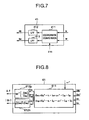
- FIG. 7 A block diagram of Fig. 7 is useful in explaining the contents of computation in the coordinate converter 41.
- Detection currents iu and iw delivered out of the motor current detector 32 and phase ⁇ dc delivered out of the speed phase estimating unit 62 are inputted to a coordinate conversion operating section 411.
- observation currents Idc and Iqc on the dc - qc coordinate axis are computed in accordance with equation (24).
- I dc i ⁇ ⁇ cos ⁇ dc + i ⁇ ⁇ sin ⁇ dc
- I qc -i ⁇ ⁇ sin ⁇ dc + i ⁇ ⁇ cos ⁇ dc
- the detection currents iu and iw of the motor 2 contain switching ripple and noise components. Then, in the coordinate converter 41, filters 412 and 413 act on a result of computation pursuant to equation (24) to eliminate the aforementioned component from the observation currents on the dc-qc coordinate axis. Accordingly, time constants of the filters 412 and 413 are set to predetermined values conforming to the switching frequency of the inverter and circuit specifications of the motor current detector 32.
- a difference ( ⁇ r*) - ⁇ r_ det is computed by an adder 50 and inputted to the speed controller 51.
- the speed controller 51 computes a torque command ⁇ * for causing the ⁇ r_det to follow the ⁇ r* and delivers the command.
- the current command generator 52 determines dc axis current command value Idc* and qc axis current command value Iqc* and delivers them. These command values are so determined as to minimize a predetermined evaluation function in accordance with the operation condition.
- the d axis current command value Idc* delivered out of the current command generator 52 and the d axis current Idc delivered out of the coordinate converter 41 are inputted to an adder 53 and a difference between them is computed.
- the d axis current controller 42d computes a compensation voltage for causing the value of (Idc*) - Idc to be zero and delivers d axis compensation voltage VId.
- the current command generator 52 delivers q axis current command Iqc* and the coordinate converter 41 delivers q axis current Iqc. These command and current are inputted to an adder 54 and a difference between them is computed.
- the q axis current controller 42 q computes a compensation voltage for causing the value of (Iqc*) - Iqc to be zero and q axis compensation voltage VI q is delivered. Further, d axis current command value Idc *, q axis current command value Iqc * and speed command ⁇ r* are inputted to the current feed- forward compensator 43 and d axis model voltage Vdm* and q axis model voltage Vqm* are delivered. These motor voltage models are expressed by equation (25) by using Id*, Iq* and ⁇ r*.
- the motor voltage models of equation (25) are derived from equation (2) and in these models, the current change term in equation (2) is omitted, voltage and current are all replaced with command values and motor constants are all replaced with setting values. Besides, when the motor 2 is driven without undergoing step-out, the rotation speed ⁇ 1 of the control axis is considered as being substantially equal to the speed command value ⁇ r * and hence ⁇ 1 is replaced with ⁇ r *.
- the sum of d axis compensation voltage VId and d axis model voltage Vdm* is computed by means of an adder 55 and a dc axis voltage Vdc* is delivered to the inverter 44. Further, the sum of q axis compensation voltage VIq and q axis model voltage Vqm* is computed by means of an adder 56 and a qc axis voltage command Vqc* is delivered to the inverse converter 44.
- the inverter 44 receives the voltage commands Vdc* and Vqc* on the control axis to generate a three-phase voltage command. More specifically, by using inputs of the dc axis voltage command Vdc* and qc axis voltage command Vqc*, three-phase voltage commands Vu*, Vv* and Vw* are computed in accordance with equation (26).
- v ⁇ * V dc * ⁇ cos ⁇ dc - V qc * ⁇ sin ⁇ dc
- v ⁇ * V dc * ⁇ sin ⁇ dc + V qc * ⁇ cos ⁇ dc
- the pulse width modulator 45 is a modulation means for performing known pulse width modulation. As necessary, the voltage detector 31 detects a voltage Edc of the DC voltage unit.
- the induced voltage/axis shift estimation-operating unit 61 will be described.
- An embodiment of the induced voltage estimation/axis shift operating unit is depicted, in block form, in Fig. 8.
- the induced voltage/axis shift estimation operating unit 61 computes an axis shift ⁇ ⁇ in the dc-qc coordinate system representing the control axis and delivers an estimated value.
- dc axis component EOdc and qc axis component EO qc of induced voltage on the dc-qc coordinate axis are computed from the observation currents Idc and Iqc, voltage commands Vdc * and Vqc * and speed command ⁇ r * pursuant to equation (27).
- Equation (27) is derived from equation (17) and in this equation, voltages in equation (17) are replaced with command values and motor constants (such as r, Lq) are all replaced with setting values.
- the rotation speed of the control axis (frequency of motor applied voltage) ⁇ 1 is considered as being substantially equal to the speed command value ⁇ r* and ⁇ 1 is replaced with ⁇ r*.
- ⁇ 1 that determined from the axis shift ⁇ ⁇ by means of the speed phase estimating unit 62 may be used.
- a phase of an induced voltage vector as viewed from the qc axis is computed and an estimation value of axis shift ⁇ ⁇ is computed by means of an operating section 612p. Further, the magnitude
- An induced voltage/axis shift estimation operating unit 61' computes an axis shift ⁇ ⁇ by using the current axis as a reference.
- magnitude V1* of the voltage commands and a phase ⁇ c of a voltage vector as viewed from the qc axis are computed by means of operating sections 613n and 613p.
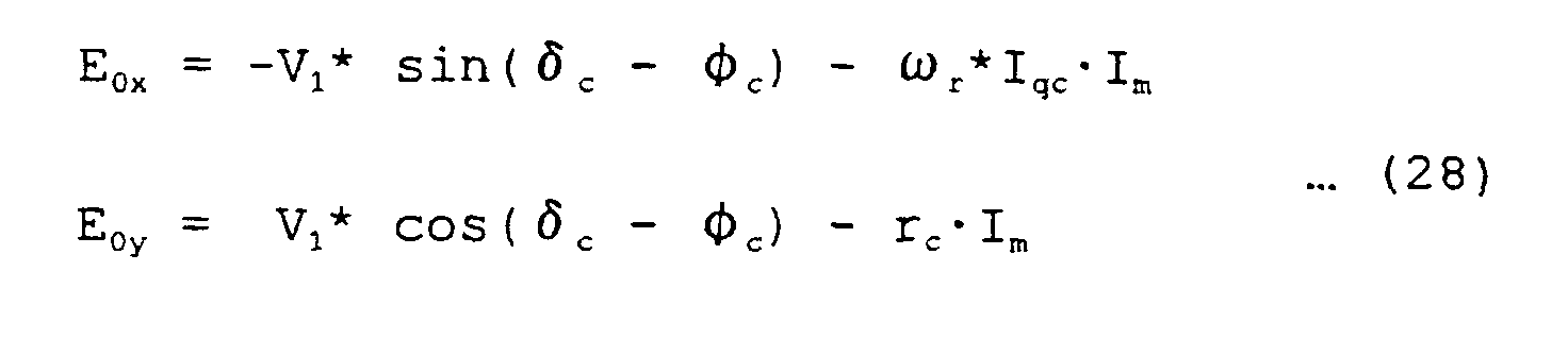
- magnitude Im of the currents and a phase ⁇ c of a current vector as viewed from the qc axis are computed by means of operating sections 614n and 614p. From the thus obtained values of V1*, ⁇ c, Im and ⁇ c, an operating section 615 computes an induced voltage pursuant to equation (28).
- Equation (28) is derived from equation (23) and in this equation, E0x represents a component orthogonal to the current axis and E0y represents a component in the current direction.
- E0x represents a component orthogonal to the current axis
- E0y represents a component in the current direction.
- An operating section 617 determines an axis shift ⁇ ⁇ from a difference between the phase ⁇ m of current axis as viewed from the induced voltage vector and the phase ⁇ c of current vector as viewed from the qc axis.
- of the obtained induced voltage vector E0 is delivered out of an operating section 616n.
- the induced voltage/axis shift estimation operating unit 61 (61') adjusts the inverter output frequency ⁇ 1 on the basis of the estimated axis shift ⁇ ⁇ .
- the control axis phase ⁇ dc leads the real axis phase ⁇ d and therefore, the inverter frequency ⁇ 1 is decreased to decelerate the rotation of the control axis.
- the control axis phase ⁇ dc lags the real axis phase ⁇ d and therefore, the inverter frequency ⁇ 1 is increased to accelerate the rotation of the control axis.
- the inverter frequency ⁇ 1 determined in the manner as above is integrated to provide a control axis phase ⁇ dc.
- a high-frequency change component is removed from the inverter frequency ⁇ 1 to provide a motor estimation value used for the speed control system.
- a difference between the axis shift ⁇ ⁇ estimated by the induced voltage/axis shift estimation operating unit 61 and the axis shift error compensating value ⁇ ⁇ * delivered out of the axis shift error compensator 7 is calculated by means of an adder 621.
- the output of the adder 621 is inputted to a PI compensator 622.
- the PI compensator 622 operates the inverter output frequency ⁇ 1 to cause the ⁇ to follow the ⁇ * .
- a means having the same function, other than the PI compensator, may otherwise be used.
- An output of the PI compensator 622 constantly changes because of the adjustment of the axis shift ⁇ ⁇ and contains a high-frequency component. Accordingly, when the output of the PI compensator 622 is used as a detection speed of the motor so as to control the motor speed, the speed control characteristic is degraded.
- the high-frequency component is removed from the ⁇ 1 by means of a low-pass filter 623 to deliver a motor speed estimation value ⁇ r_det.
- an integrator 624 integrates the inverter output frequency ⁇ 1 to deliver a phase ⁇ dc.
- of induced voltage is added to the embodiment shown in Fig. 10. Gathering from equation (9), the magnitude
- k E ⁇ r + ⁇ r (L d - L q ) ⁇ I d + (L q - L d ) ⁇ pI q
- KEC represents a setting value of induced voltage constant and Ldc and Lqc represent setting values of inductance.
- Id can be determined from the observation currents Idc and Iqc on the control axis and the axis shift ⁇ ⁇ in accordance with equation (3).
- of induced voltage and the induced voltage coefficient k in equation (30) are inputted to an integrator 625.
- /k is computed and a speed ⁇ r_est estimated from the induced voltage is delivered.
- an adder 626 an output of the PI compensator 622 and the ⁇ r_est are added together and an inverter output frequency ⁇ 1 is delivered. With this construction, a shift of ⁇ r_ est from the real speed is compensated by means of the PI compensator 622 and so, the responsibility can be improved by adjusting the control gain.
- an adder 627 the sum of ⁇ _ est and an output of PI compensator 622 removed of high-frequency components is computed and a motor estimation speed ⁇ r_ det is delivered.
- an integrator output is taken out as a quantity resulting from removal of the high-frequency components from the output of the PI compensator 622. This is because the parameter setting value in the controller has an error and an error contained in ⁇ r_est is to be compensated.
- the axis shift error compensator 7 in the present embodiment is a means for compensating the influence of an error when the parameter setting value of the controller has the error.
- a value to ⁇ * usually set to zero the axis shift between the real axis and the control axis can be given by the sum of the axis shift ⁇ ⁇ e due to the parameter error and the axis shift error compensation value ⁇ ⁇ *.
- the real axis can coincide with the control axis.
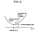
- a method of adjusting the axis shift error compensation value ⁇ * will be described. It is assumed that during an i- th control period, a value is set to the axis shift error compensation value ⁇ ⁇ * and the magnitude of motor current is Im(i). Next, it is assumed that during an (i + 1) th control period, a randomly selected value is substituted to ⁇ ⁇ * and as a result, the magnitude of motor current is changed to Im(i + 1). If Im(i + 1) is smaller than Im(i), the setting value used during (i + 1) th control period is selected as Id* or ⁇ ⁇ *. By repeating the above operation, a setting value that minimizes the motor current Im can be determined.
- the rotor position is estimated from the phase of an induced voltage of the salient-pole machine, on the basis of the fact that the induced voltage of the salient-pole machine can be obtained by subtracting a voltage drop across the resistor and a voltage drop across the inductance from a motor applied voltage, the concept of a virtual voltage independent of the rotor position substituting for the inductance voltage drop dependent on the rotor position is introduced and besides, the vector relation that does not cause the phase of the induced voltage to change by using the motor constant Lq as the inductance is derived, thereby ensuring that the phase of the induced voltage can be estimated correctly on the basis of observable quantities.
- the vector in the voltage relation of salient-pole machine in which the concept of the virtual voltage drop is introduced can stand when either the control axis is used as a reference or the current axis is used as a reference and therefore, the phase of the induced voltage can be estimated by values observable from the control axis or the current axis.
- the method for estimating the axis shift angle ⁇ on the basis of equation (17) or (23) has been described but by using equation (16), the axis shift ⁇ ⁇ can be estimated similarly.
- the axis shift ⁇ ⁇ can be estimated similarly.
- differential components of observation currents Idc and Iqc are taken into consideration.
- a vector relation not causing the phase of the induced voltage to change can be introduced by using the inductance constant Ld so that the phase of the induced voltage may be estimated correctly on the basis of observable values.
- the phase of the induced voltage of salient-pole machine can be estimated from observable quantities without resort to position sensor and the axis shift ⁇ ⁇ can be computed with high accuracy directly from the estimated phase, with the result that an excellent control system for synchronous motor without resort to position sensor can be provided which can be stable and free from step-out even when a large axis shift occurs during, for example, an abrupt load change or abrupt accelerating/decelerating operation.
- the concept of the axis shift error compensation value ⁇ ⁇ * is introduced and the frequency ⁇ 1 of motor applied voltage or torque command value ⁇ * is so modified as to make zero the ⁇ ⁇ * - ⁇ ⁇ .
- the setting value of ⁇ * is so tuned as to minimize the motor current in a stable condition of the motor.
- the salient synchronous motor using the permanent magnet has been handled.
- a salient synchronous motor not using a magnet a synchronous reluctance motor is known.
- a voltage equation of the synchronous reluctance motor has a format in which KE term in the voltage equation (2) of the permanent magnet synchronous motor is made to be zero.
- the axis shift estimation equations (17) and (23) derived in the present invention do not use the induced voltage constant KE in the operation. Besides, reduction depending on KE is not effected in derivation of these equations. Accordingly, even to the synchronous reluctance motor, the estimation method of axis shift ⁇ and the control method without resort to position sensor according to the invention can be applied.
Landscapes
- Engineering & Computer Science (AREA)
- Power Engineering (AREA)
- Control Of Ac Motors In General (AREA)
- Control Of Motors That Do Not Use Commutators (AREA)
Description








Accordingly, the method of estimating the axis shift Δ by using equation (17) is superior to the prior arts 2 and 3 from the standpoint of robustness.




Claims (8)
- A method of estimating a rotor position of a synchronous motor having saliency comprising the steps of:wherein ΔΘ represents the axis shift angle between a real position and a virtual rotor position from control viewpoint , Vdc, Vqc, Idc and Iqc represent observable voltages and currents on the control axis , r represents the resistance of the motor winding ω1 represents the rotary speed of the control axis, Lq represents an inductance constant, V1 and Φv represent magnitude and phase of the motor voltage , Im represents the magnitude of a motor current component, and Φc is the phase of the current axis as viewed from the qc-axis .estimating an induced voltage of the synchronous motor (2) from a vector difference between a vector of a motor applied voltage (V1) and vectors of voltage drops (VL', Vr) due to resistance and inductance of a motor winding, wherein for determining said voltage drop (VL') due to inductance as a quantity dephased by a predetermined amount from a motor current an inductance constant number Lq of said motor winding is used as a predetermined value; andcalculating the phase of the induced voltage from the estimated induced voltage to estimate the rotor position, the phase of the induced voltage being estimated with the following equation:or with the following equation:


- A method according to claim 1, wherein said vector of voltage drop (VL') due to inductance of said motor winding is a vector 90° leading said vector of motor current by 90°.
- A method of controlling a synchronous motor having saliency without resort to a position sensor, comprising the steps of:estimating a rotor position of said synchronous motor by the method of one of the claims 1 to 4, whereineither when an axis shift angle estimated from the phase of said induced voltage indicates that the virtual rotor position leads the actual rotor position in the rotation direction of the rotor, a frequency of the motor applied voltage is decreased to decrease the rotation speed of the virtual rotor position, and, when the estimated axis shift angle indicates lagging increasing the frequency of the motor applied voltage to increase the rotation speed of the virtual rotor position,or when the axis shift angle indicates that the virtual rotor position leads the actual rotor position in the rotation direction of the rotor, a torque command value for the motor is increased to increase the rotation speed of the actual rotor position, and, when the estimated axis shift angle indicates lagging the torque command value for the motor is decreased to decrease the rotation speed of the actual rotor position.
- A method according to claim 3, wherein an error compensation value (Δ*) of the axis shift angle indicated by said phase of said induced voltage is set and said frequency of said motor applied voltage or said torque command value is so controlled as to minimize the difference between said axis shift angle (Δ) said error compensation value.
- A method according to claim 4, wherein setting of said error compensation value is so adjusted as to minimize said motor current under a condition that the rotation speed and the load on said motor are constant.
- A system of controlling a synchronous motor having saliency without resort to position sensor, comprising:an inverter (13) for converting a DC voltage into a three-phase AC voltage of variable voltage and variable frequency andapplying the three-phase AC voltage to the synchronous motor (2) having saliency;a current detector (32) for detecting a motor current;a voltage command operating unit (42d, 42q, 43, 44; 53 to 55) for preparing voltage command values (Vdc*, Vqc*) by using a virtual rotor position (dc) in order that the magnitude and phase of detected three-phase motor current follow command values of the magnitude and phase of the motor current, respectively;a current command generating unit (50 to 52) applied with a motor speed command value (ωr*) to prepare said command values of the magnitude and phase of motor current on the basis of the motor speed command value (ωr*) and a motor speed estimation value (ωr_det) ;an induced voltage estimating unit (61) for estimating an induced voltage of said motor by using the detected motor current, said voltage command value and one of said motor speed command value (ωr*) and a frequency of the motor applied voltage as well as the resistance and an inductance constant number Lq of a motor winding, for estimating an axis shift angle (Δ) indicative of a shift between the virtual rotor position from the control viewpoint and a real position and delivering the axis shift angle; the axis shift angle (Δ) being computed with the equation:or with the equation
 wherein Vdc, Vqc, Idc and Iqc represent observable voltages and currents on the control axis , r represents the resistance of the motor winding ω1 represents the rotary speed of the control axis, Lq represents an inductance constant, V1 and Φv represent magnitude and phase of the motor voltage , Im represents the magnitude of a motor current component, and Φc is the phase of the current axis as viewed from the qc-axis , and
 a speed phase estimating unit (62) for determining the motor speed estimation value (ωr_det) and the virtual rotor position (dc) from the axis shift angle (Δ) and delivering them.
 - A system according to claim 6, wherein said speed phase estimating unit (62) comprises means for computing the frequency of said motor applied voltage from the axis shift angle (Δ) to deliver it, and for determining the motor speed estimation value (ωr_det) and the virtual rotor position ( dc) from the computed frequency of motor applied voltage to deliver them.
- A synchronous motor control system without resort to position sensor according to claim 6 or 7, further comprising an error compensating unit (7) for applying an error compensation value (Δ*) of said motor parameter to an estimated value of said axis shift angle (Δ), wherein said speed phase estimating unit (62) computes the inputted axis shift angle (Δ) to cause it to follow said error compensation value and delivers a motor speed estimation value (ωr_det).
Applications Claiming Priority (2)
| Application Number | Priority Date | Filing Date | Title |
|---|---|---|---|
| JP2000065714A JP3411878B2 (en) | 2000-03-06 | 2000-03-06 | Method for estimating rotor position of synchronous motor, control method without position sensor, and control device |
| JP2000065714 | 2000-03-06 |
Publications (3)
| Publication Number | Publication Date |
|---|---|
| EP1133050A2 EP1133050A2 (en) | 2001-09-12 |
| EP1133050A3 EP1133050A3 (en) | 2002-02-06 |
| EP1133050B1 true EP1133050B1 (en) | 2005-11-23 |
Family
ID=18585198
Family Applications (1)
| Application Number | Title | Priority Date | Filing Date |
|---|---|---|---|
| EP00118260A Expired - Lifetime EP1133050B1 (en) | 2000-03-06 | 2000-09-04 | Method of estimating a rotor position of synchronous motor, method of controlling synchronous motor with no position sensor and a controller of synchronous motor |
Country Status (4)
| Country | Link |
|---|---|
| US (1) | US6396229B1 (en) |
| EP (1) | EP1133050B1 (en) |
| JP (1) | JP3411878B2 (en) |
| DE (1) | DE60024222T2 (en) |
Cited By (3)
| Publication number | Priority date | Publication date | Assignee | Title |
|---|---|---|---|---|
| US8704475B2 (en) | 2009-03-09 | 2014-04-22 | Meidensha Corporation | Current source inverter device |
| RU2561879C2 (en) * | 2009-12-11 | 2015-09-10 | Лабиналь Пауэр Системз | Control device of synchronous machine with permanent magnets |
| EP3826169A1 (en) | 2019-11-25 | 2021-05-26 | KOSTAL Drives Technology GmbH | Method and device for controlling a synchronous machine without a position sensor by means of a unique allocation of the flow linkage to the rotor position |
Families Citing this family (199)
| Publication number | Priority date | Publication date | Assignee | Title |
|---|---|---|---|---|
| JP3979561B2 (en) * | 2000-08-30 | 2007-09-19 | 株式会社日立製作所 | AC motor drive system |
| JP3634270B2 (en) * | 2001-02-02 | 2005-03-30 | 株式会社豊田中央研究所 | Motor drive circuit |
| US6728580B2 (en) * | 2001-02-20 | 2004-04-27 | General Electric Company | Method and apparatus for estimating time to failure acceleration factor |
| WO2002091558A1 (en) * | 2001-04-24 | 2002-11-14 | Mitsubishi Denki Kabushiki Kaisha | System for controlling synchronous motor |
| JP3485905B2 (en) * | 2001-04-26 | 2004-01-13 | 本田技研工業株式会社 | Motor control device |
| JP3965934B2 (en) * | 2001-05-09 | 2007-08-29 | 株式会社日立製作所 | Moving body control device and moving body system |
| JP3818086B2 (en) * | 2001-06-01 | 2006-09-06 | 株式会社日立製作所 | Synchronous motor drive |
| JP3867518B2 (en) * | 2001-06-06 | 2007-01-10 | 株式会社日立製作所 | Sensorless control system for synchronous motor |
| KR100428505B1 (en) * | 2001-07-06 | 2004-04-28 | 삼성전자주식회사 | Method of speed speed and flux estimation for induction motor |
| JP4075338B2 (en) * | 2001-07-18 | 2008-04-16 | 株式会社豊田自動織機 | Control method of electric compressor |
| JP3668870B2 (en) * | 2001-08-09 | 2005-07-06 | 株式会社日立製作所 | Synchronous motor drive system |
| JP2003079200A (en) * | 2001-09-04 | 2003-03-14 | Hitachi Ltd | Motor drive system |
| WO2003043172A1 (en) | 2001-11-12 | 2003-05-22 | International Rectifier Corporation | Rotor angle estimation for permanent magnet synchronous motor drive |
| US7066034B2 (en) * | 2001-11-12 | 2006-06-27 | International Rectifier Corporation | Start-up method and system for permanent magnet synchronous motor drive |
| DE50305900D1 (en) * | 2002-02-13 | 2007-01-18 | Continental Teves Ag & Co Ohg | PROCEDURE FOR ERROR DETECTION FOR ELECTRIC MOTORS |
| SG161736A1 (en) * | 2002-02-25 | 2010-06-29 | Daikin Ind Ltd | Motor control method and its apparatus |
| US6762573B2 (en) * | 2002-02-26 | 2004-07-13 | General Motors Corporation | System and method for estimating rotor position of a permanent magnet motor |
| JP4319377B2 (en) * | 2002-05-31 | 2009-08-26 | 三菱電機株式会社 | Permanent magnet motor drive device, hermetic compressor, refrigeration cycle device, and permanent magnet generator drive device |
| US6686715B2 (en) * | 2002-06-14 | 2004-02-03 | Champion Microelectronic Corp. | Motor control device |
| US7423395B2 (en) * | 2002-07-08 | 2008-09-09 | Kabushiki Kaisha Yaskawa Denki | Sensorless vector control method for alternating-current motor and control apparatus therefor |
| JP3972124B2 (en) * | 2002-07-10 | 2007-09-05 | 株式会社日立製作所 | Synchronous motor speed control device |
| JP3914107B2 (en) * | 2002-07-12 | 2007-05-16 | 本田技研工業株式会社 | DC brushless motor control device |
| JP3914108B2 (en) * | 2002-07-15 | 2007-05-16 | 本田技研工業株式会社 | DC brushless motor control device |
| KR20040018716A (en) * | 2002-08-26 | 2004-03-04 | 삼성전자주식회사 | Apparatus and method for controlling velocity of BLDC motor |
| JP4059039B2 (en) * | 2002-08-30 | 2008-03-12 | 株式会社安川電機 | Control device for synchronous motor |
| JP3695436B2 (en) * | 2002-09-18 | 2005-09-14 | 株式会社日立製作所 | Position sensorless motor control method and apparatus |
| US6979967B2 (en) * | 2002-10-15 | 2005-12-27 | International Rectifier Corporation | Efficiency optimization control for permanent magnet motor drive |
| US6856109B2 (en) * | 2002-10-15 | 2005-02-15 | International Rectifier Corporation | Efficiency optimization control for permanent magnet motor drive |
| US20040100220A1 (en) * | 2002-11-25 | 2004-05-27 | Zhenxing Fu | Weighted higher-order proportional-integral current regulator for synchronous machines |
| JP4067949B2 (en) | 2002-12-03 | 2008-03-26 | サンデン株式会社 | Motor control device |
| JP4055992B2 (en) | 2002-12-25 | 2008-03-05 | サンデン株式会社 | Inverter current detector |
| JP2004282969A (en) | 2003-03-19 | 2004-10-07 | Hitachi Ltd | Control device and control method for AC motor |
| US7075266B2 (en) | 2003-03-28 | 2006-07-11 | Hitachi, Ltd. | Apparatus for controlling an a. c. motor |
| JP4572582B2 (en) * | 2003-06-02 | 2010-11-04 | 株式会社安川電機 | Induction motor control device |
| EP1646138B1 (en) * | 2003-07-16 | 2012-11-28 | Mitsubishi Denki Kabushiki Kaisha | Device for estimating pole position of synchronous motor |
| US7262536B2 (en) * | 2003-08-11 | 2007-08-28 | General Motors Corporation | Gearless wheel motor drive system |
| US7042193B2 (en) * | 2003-08-28 | 2006-05-09 | Mitsubishi Denki Kabushiki Kaisha | Control apparatus for rotating machine |
| EP1685644A4 (en) * | 2003-11-10 | 2008-12-31 | Int Rectifier Corp | Efficiency optimization control for permanent magnet motor drive |
| JP4221307B2 (en) * | 2004-01-07 | 2009-02-12 | 日立アプライアンス株式会社 | Synchronous motor control device, electrical equipment and module |
| US7184927B2 (en) * | 2004-03-26 | 2007-02-27 | Honeywell International Inc. | Adaptive position sensing method and apparatus for synchronous motor generator system |
| US7075264B2 (en) | 2004-03-31 | 2006-07-11 | Honeywell International Inc. | Instantaneous power floating frame controller |
| JP4619040B2 (en) * | 2004-05-14 | 2011-01-26 | アイシン・エィ・ダブリュ株式会社 | Electric drive control device, electric drive control method, and program |
| US7208908B2 (en) * | 2004-07-12 | 2007-04-24 | Honeywell International Inc. | Apparatus and method to control torque and voltage of an AC machine |
| JP4517793B2 (en) * | 2004-09-14 | 2010-08-04 | 株式会社日立製作所 | Permanent magnet synchronous motor control device and module |
| US7211984B2 (en) * | 2004-11-09 | 2007-05-01 | General Motors Corporation | Start-up and restart of interior permanent magnet machines |
| JP4589093B2 (en) | 2004-12-10 | 2010-12-01 | 日立オートモティブシステムズ株式会社 | Synchronous motor driving apparatus and method |
| US7432677B2 (en) * | 2004-12-16 | 2008-10-07 | Seagate Technology Llc | Closed-loop rotational control of a brushless dc motor |
| WO2006073378A1 (en) * | 2005-01-07 | 2006-07-13 | Ronald De Four | A self starting method and an apparatus for sensorless commutation of brushless dc motors |
| JP4644010B2 (en) * | 2005-02-14 | 2011-03-02 | 日本電産株式会社 | Vector control method and apparatus for synchronous reluctance motor |
| JP2006238631A (en) * | 2005-02-25 | 2006-09-07 | Mitsubishi Heavy Ind Ltd | MOTOR CONTROLLING METHOD USING Id/Iq TABLE |
| JP4574412B2 (en) * | 2005-03-30 | 2010-11-04 | 本田技研工業株式会社 | Hybrid vehicle motor constant detection device and hybrid vehicle motor control device |
| DE112006001604T8 (en) | 2005-06-27 | 2008-11-13 | The University Of Tokushima | Power conversion control device, power conversion control method, and power conversion control program |
| JP4729356B2 (en) * | 2005-07-29 | 2011-07-20 | 株式会社日立製作所 | Motor controller, washing machine, air conditioner and electric oil pump |
| JP4972135B2 (en) * | 2005-08-26 | 2012-07-11 | 三洋電機株式会社 | Motor control device |
| JP4480696B2 (en) | 2005-08-26 | 2010-06-16 | 三洋電機株式会社 | Motor control device |
| JP4674516B2 (en) * | 2005-09-27 | 2011-04-20 | 株式会社デンソー | Method for estimating magnetic pole position of synchronous motor |
| JP4674525B2 (en) | 2005-10-13 | 2011-04-20 | 株式会社デンソー | Magnetic pole position estimation method and motor control apparatus |
| JP4655871B2 (en) * | 2005-10-19 | 2011-03-23 | 株式会社日立製作所 | Field weakening vector control device and module for permanent magnet synchronous motor |
| JP4631672B2 (en) * | 2005-11-29 | 2011-02-16 | 株式会社デンソー | Magnetic pole position estimation method, motor speed estimation method, and motor control apparatus |
| GB0526274D0 (en) | 2005-12-23 | 2006-02-01 | Trw Ltd | Electric motor control |
| JP4989075B2 (en) | 2006-01-11 | 2012-08-01 | 株式会社日立産機システム | Electric motor drive control device and electric motor drive system |
| JP4879649B2 (en) * | 2006-03-22 | 2012-02-22 | 本田技研工業株式会社 | Electric motor control device |
| JP4198162B2 (en) * | 2006-04-07 | 2008-12-17 | 三洋電機株式会社 | Motor control device |
| JP4895703B2 (en) | 2006-06-28 | 2012-03-14 | 三洋電機株式会社 | Motor control device |
| JP4434184B2 (en) * | 2006-08-17 | 2010-03-17 | アイシン・エィ・ダブリュ株式会社 | Method and apparatus for feedback control of electric motor |
| JP2008048570A (en) * | 2006-08-21 | 2008-02-28 | Yaskawa Electric Corp | AC motor control device and control method thereof |
| JP2008086117A (en) * | 2006-09-27 | 2008-04-10 | Aisin Seiki Co Ltd | Electric fluid pump |
| JP4811727B2 (en) * | 2006-11-01 | 2011-11-09 | 株式会社安川電機 | Permanent magnet field synchronous motor controller |
| JP4383442B2 (en) | 2006-12-27 | 2009-12-16 | 三洋電機株式会社 | Motor control device and motor drive system |
| JP4284355B2 (en) | 2006-12-28 | 2009-06-24 | 株式会社日立産機システム | High response control device for permanent magnet motor |
| FR2911698B1 (en) * | 2007-01-24 | 2009-07-10 | Airbus France Sas | DEVICE FOR CONTROLLING ELECTROMECHANICAL ACTUATOR. |
| JP4519864B2 (en) | 2007-01-29 | 2010-08-04 | 三菱電機株式会社 | AC rotating machine electrical constant measuring method and AC rotating machine control apparatus used for carrying out this measuring method |
| EP1981164A3 (en) | 2007-04-13 | 2016-12-07 | Sanyo Electric Co., Ltd. | Motor control device |
| JP4984057B2 (en) * | 2007-04-26 | 2012-07-25 | 富士電機株式会社 | Control device for permanent magnet type synchronous motor |
| JP5445892B2 (en) * | 2007-04-26 | 2014-03-19 | 富士電機株式会社 | Control device for permanent magnet type synchronous motor |
| JP4297953B2 (en) | 2007-06-22 | 2009-07-15 | 三洋電機株式会社 | Motor control device and compressor |
| EP2019482B1 (en) * | 2007-07-26 | 2010-03-31 | Baumüller Nürnberg Gmbh | System for determining the position and speed for a permanent magnet rotor of an electric machine |
| JP4476314B2 (en) | 2007-08-10 | 2010-06-09 | 三洋電機株式会社 | Motor control device and compressor |
| US8950206B2 (en) | 2007-10-05 | 2015-02-10 | Emerson Climate Technologies, Inc. | Compressor assembly having electronics cooling system and method |
| US7895003B2 (en) | 2007-10-05 | 2011-02-22 | Emerson Climate Technologies, Inc. | Vibration protection in a variable speed compressor |
| US8459053B2 (en) | 2007-10-08 | 2013-06-11 | Emerson Climate Technologies, Inc. | Variable speed compressor protection system and method |
| US8448459B2 (en) * | 2007-10-08 | 2013-05-28 | Emerson Climate Technologies, Inc. | System and method for evaluating parameters for a refrigeration system with a variable speed compressor |
| US8418483B2 (en) | 2007-10-08 | 2013-04-16 | Emerson Climate Technologies, Inc. | System and method for calculating parameters for a refrigeration system with a variable speed compressor |
| US8539786B2 (en) * | 2007-10-08 | 2013-09-24 | Emerson Climate Technologies, Inc. | System and method for monitoring overheat of a compressor |
| US20090092501A1 (en) * | 2007-10-08 | 2009-04-09 | Emerson Climate Technologies, Inc. | Compressor protection system and method |
| US20090092502A1 (en) * | 2007-10-08 | 2009-04-09 | Emerson Climate Technologies, Inc. | Compressor having a power factor correction system and method |
| US9541907B2 (en) * | 2007-10-08 | 2017-01-10 | Emerson Climate Technologies, Inc. | System and method for calibrating parameters for a refrigeration system with a variable speed compressor |
| JP5386813B2 (en) * | 2007-10-30 | 2014-01-15 | 株式会社ジェイテクト | Sensorless control device for brushless motor |
| JP5156352B2 (en) * | 2007-11-30 | 2013-03-06 | 株式会社日立製作所 | AC motor control device |
| JP5130031B2 (en) * | 2007-12-10 | 2013-01-30 | 株式会社日立製作所 | Position sensorless control device for permanent magnet motor |
| TWI341641B (en) * | 2007-12-24 | 2011-05-01 | Delta Electronics Inc | Apparatus and method for sensorless control of induction motor |
| US7839106B2 (en) * | 2008-03-05 | 2010-11-23 | Gm Global Technology Operations, Inc. | System and methods involving dynamic closed loop motor control and flux weakening |
| JP2009268267A (en) | 2008-04-25 | 2009-11-12 | Sanyo Electric Co Ltd | Motor controller and generator controller |
| JP5178335B2 (en) * | 2008-06-17 | 2013-04-10 | 株式会社日立製作所 | AC motor control device |
| JP5534292B2 (en) | 2008-06-30 | 2014-06-25 | 株式会社ジェイテクト | Vehicle steering system |
| US8237385B2 (en) * | 2008-09-15 | 2012-08-07 | Texas Instruments Incorporated | Systems and methods for detecting position for a brushless DC motor |
| JP4746667B2 (en) * | 2008-11-26 | 2011-08-10 | 本田技研工業株式会社 | Motor phase current estimation device and motor magnetic pole position estimation device |
| US20100141191A1 (en) * | 2008-12-04 | 2010-06-10 | Chen Liyong | Systems and methods for determining a commutation state for a brushless dc motor |
| JP5376215B2 (en) | 2009-01-30 | 2013-12-25 | 株式会社ジェイテクト | Motor control device |
| JP4361598B1 (en) * | 2009-03-09 | 2009-11-11 | 山洋電気株式会社 | Sensorless AC motor control device |
| JP5495018B2 (en) | 2009-03-12 | 2014-05-21 | 株式会社ジェイテクト | Motor control device |
| US20100237817A1 (en) * | 2009-03-23 | 2010-09-23 | Jingbo Liu | Method and Apparatus for Estimating Rotor Position in a Sensorless Synchronous Motor |
| CN102362425B (en) * | 2009-03-25 | 2014-06-04 | 三菱电机株式会社 | Controls for rotating electrical machines |
| CN102326329B (en) * | 2009-03-30 | 2015-12-16 | 株式会社日立制作所 | AC motor control device and AC motor drive system |
| JP5526975B2 (en) * | 2009-05-13 | 2014-06-18 | 株式会社安川電機 | Electric motor control device and control method thereof |
| JP4987032B2 (en) * | 2009-05-18 | 2012-07-25 | 本田技研工業株式会社 | Rotor angle estimation device |
| DE102009030884A1 (en) * | 2009-06-23 | 2011-01-05 | GÄRTNER ELECTRONIC-DESIGN GmbH | Method and device for compensating load influences in permanent-magnet motors |
| JP5561516B2 (en) | 2009-07-06 | 2014-07-30 | 株式会社ジェイテクト | Motor control device and vehicle steering device |
| US8476873B2 (en) * | 2009-08-10 | 2013-07-02 | Emerson Climate Technologies, Inc. | System and method for current balancing |
| US8264192B2 (en) | 2009-08-10 | 2012-09-11 | Emerson Climate Technologies, Inc. | Controller and method for transitioning between control angles |
| US8344706B2 (en) * | 2009-08-10 | 2013-01-01 | Emerson Climate Technologies, Inc. | System and method for rejecting DC current in power factor correction systems |
| US8508166B2 (en) * | 2009-08-10 | 2013-08-13 | Emerson Climate Technologies, Inc. | Power factor correction with variable bus voltage |
| US8264860B2 (en) * | 2009-08-10 | 2012-09-11 | Emerson Climate Technologies, Inc. | System and method for power factor correction frequency tracking and reference generation |
| US8493014B2 (en) * | 2009-08-10 | 2013-07-23 | Emerson Climate Technologies, Inc. | Controller and method for estimating, managing, and diagnosing motor parameters |
| US8406021B2 (en) * | 2009-08-10 | 2013-03-26 | Emerson Climate Technologies, Inc. | System and method for reducing line current distortion |
| US8698433B2 (en) | 2009-08-10 | 2014-04-15 | Emerson Climate Technologies, Inc. | Controller and method for minimizing phase advance current |
| US8358098B2 (en) * | 2009-08-10 | 2013-01-22 | Emerson Climate Technologies, Inc. | System and method for power factor correction |
| GB0916543D0 (en) * | 2009-09-21 | 2009-10-28 | Melexis Tessenderlo Nv | Control of sinusoidally driven brushless dc (bldc) motors |
| JP5641299B2 (en) * | 2009-10-28 | 2014-12-17 | 株式会社ジェイテクト | Motor control device and vehicle steering device |
| JP5532295B2 (en) | 2009-11-12 | 2014-06-25 | 株式会社ジェイテクト | Motor control device and vehicle steering device |
| JP5440846B2 (en) | 2009-11-16 | 2014-03-12 | 株式会社ジェイテクト | Motor control device and vehicle steering device |
| JP5614583B2 (en) | 2009-11-17 | 2014-10-29 | 株式会社ジェイテクト | Motor control device and vehicle steering device |
| KR101101471B1 (en) * | 2010-01-08 | 2012-01-03 | 엘에스산전 주식회사 | Operation control device and method of inverter system |
| JP5155344B2 (en) | 2010-01-15 | 2013-03-06 | 本田技研工業株式会社 | Electric motor magnetic pole position estimation device |
| US9013074B2 (en) | 2010-05-25 | 2015-04-21 | Regal Beloit America, Inc. | Resilient rotor assembly for interior permanent magnet motor |
| US8593091B2 (en) * | 2010-06-25 | 2013-11-26 | Magna E-Car Systems Of America, Inc. | DQ vector control system providing stable, high efficiency operation of electric motor |
| DE102010038295A1 (en) * | 2010-07-22 | 2012-01-26 | Robert Bosch Gmbh | Method and device for sensorless position detection of an electronically commutated electrical machine |
| US8520355B2 (en) | 2010-07-27 | 2013-08-27 | Regal Beloit America, Inc. | Methods and systems for transient voltage protection |
| JP5692569B2 (en) | 2010-08-23 | 2015-04-01 | 株式会社ジェイテクト | Vehicle steering system |
| JP5422527B2 (en) | 2010-09-09 | 2014-02-19 | 株式会社日立カーエンジニアリング | Brushless motor control device and brushless motor system |
| DE102010041021A1 (en) * | 2010-09-20 | 2012-03-22 | Robert Bosch Gmbh | Method and device for sensorless determination of a rotor position of an electrical machine |
| JP5645956B2 (en) * | 2010-11-05 | 2014-12-24 | 三菱電機株式会社 | Power converter |
| KR101382305B1 (en) * | 2010-12-06 | 2014-05-07 | 현대자동차주식회사 | Motor control device for hybrid vehicle |
| US8692432B2 (en) | 2010-12-07 | 2014-04-08 | Regal Beloit America, Inc. | Permanent magnet rotors and methods of assembling the same |
| KR101761740B1 (en) | 2011-02-01 | 2017-07-26 | 삼성전자 주식회사 | Apparatus for estimating inductance of permanent magnet synchronous motor and method the same |
| JP5652610B2 (en) | 2011-02-15 | 2015-01-14 | サンデン株式会社 | Motor control device |
| JP5697036B2 (en) * | 2011-04-22 | 2015-04-08 | サンデン株式会社 | Motor control device |
| CN102223134B (en) * | 2011-06-10 | 2013-07-10 | 李庆松 | Device and method for online distinguishing parameters of servo system of permanent-magnet synchronous motor |
| WO2013024780A1 (en) * | 2011-08-15 | 2013-02-21 | 株式会社明電舎 | Pm motor position-sensorless control device |
| US8860342B2 (en) | 2011-09-15 | 2014-10-14 | Curtiss-Wright Electro-Mechanical Corporation | System and method for controlling a permanent magnet motor |
| WO2013084461A1 (en) * | 2011-12-09 | 2013-06-13 | パナソニック株式会社 | Electric motor control device |
| CN104221273B (en) | 2012-04-12 | 2016-10-05 | 株式会社日立制作所 | motor drive |
| JP5853097B2 (en) * | 2012-04-12 | 2016-02-09 | 株式会社日立製作所 | Three-phase synchronous motor drive device, integrated three-phase synchronous motor, positioning device and pump device |
| US9634593B2 (en) | 2012-04-26 | 2017-04-25 | Emerson Climate Technologies, Inc. | System and method for permanent magnet motor control |
| JP6010752B2 (en) * | 2012-05-08 | 2016-10-19 | パナソニックIpマネジメント株式会社 | Motor driving method and motor control device |
| KR20140003851A (en) * | 2012-06-29 | 2014-01-10 | 삼성전기주식회사 | Motor, measure method for distance of air gap between rotor and stator assembly, and control method using the same |
| EP2883302B1 (en) | 2012-08-10 | 2020-09-30 | Emerson Climate Technologies, Inc. | Motor drive control using pulse-width modulation pulse skipping |
| JP5696700B2 (en) * | 2012-08-29 | 2015-04-08 | トヨタ自動車株式会社 | Rotor position estimation device, motor control system, and rotor position estimation method |
| JP5978074B2 (en) * | 2012-09-03 | 2016-08-24 | ジョンソンコントロールズ ヒタチ エア コンディショニング テクノロジー(ホンコン)リミテッド | Motor drive device and compressor using the same |
| CN102857161B (en) * | 2012-09-24 | 2015-04-29 | 海信(山东)空调有限公司 | Air-conditioning apparatus and permanent magnet synchronous motor control method and device of air-conditioning apparatus |
| CN103701372B (en) * | 2012-09-27 | 2017-07-04 | 比亚迪股份有限公司 | A kind of step failing out detecting method of synchronous motor |
| CN103701377B (en) * | 2012-09-27 | 2017-05-31 | 比亚迪股份有限公司 | A kind of step failing out detecting method of synchronous motor |
| US8947032B2 (en) | 2012-11-29 | 2015-02-03 | Electro-Motive Diesel, Inc. | System and method for estimating the position of a wound rotor synchronous machine |
| JP6022951B2 (en) * | 2013-01-18 | 2016-11-09 | トヨタ自動車株式会社 | Electric power steering device |
| CN104052274B (en) * | 2013-03-13 | 2017-11-28 | Lg电子株式会社 | Power-converting device and the air conditioner for possessing the power-converting device |
| CN103346723B (en) * | 2013-05-22 | 2016-01-13 | 四川长虹电器股份有限公司 | A kind of position-sensorless control device and method for detecting position |
| DE102013212876A1 (en) * | 2013-07-02 | 2015-01-08 | Robert Bosch Gmbh | Method and device for the sensorless detection of a rotor position of an electrical machine |
| CN105432015A (en) * | 2013-08-09 | 2016-03-23 | 株式会社安川电机 | Motor drive system and motor control device |
| JP6211353B2 (en) * | 2013-09-03 | 2017-10-11 | Ntn株式会社 | Electric vehicle control device |
| KR101736531B1 (en) * | 2013-10-18 | 2017-05-16 | 엘에스산전 주식회사 | Apparatus for restarting medium-voltage inverter |
| FI125168B (en) * | 2013-12-16 | 2015-06-30 | Vacon Oyj | Identification of the rotor angle of a PMSM motor |
| CN103684187B (en) * | 2013-12-31 | 2016-09-21 | 清华大学 | A kind of permagnetic synchronous motor Id=0 current Control Algorithm |
| FR3016256B1 (en) * | 2014-01-07 | 2016-01-22 | Leroy Somer Moteurs | METHOD FOR DETERMINING THE POLARITY OF A ROTOR POLE OF A ROTATING ELECTRIC MACHINE |
| CN103916063B (en) * | 2014-03-31 | 2017-06-06 | 广东威灵电机制造有限公司 | The location recognition method and device of the rotor of electric machine control system and motor |
| DE102014217005A1 (en) * | 2014-08-26 | 2016-03-03 | BSH Hausgeräte GmbH | Method for braking a compressor and compressors of a refrigerating appliance, air conditioner or a heat pump and refrigeration device, air conditioner or heat pump with it |
| WO2016038992A1 (en) * | 2014-09-12 | 2016-03-17 | 三菱電機株式会社 | Ac rotating machine control device and method for calculating magnetic pole position correction amount |
| JP6052323B2 (en) * | 2015-04-02 | 2016-12-27 | 株式会社明電舎 | Rotor position detector abnormality determination device for motor control device |
| CN107580578B (en) * | 2015-05-11 | 2020-07-07 | 蒂森克虏伯普利斯坦股份公司 | Electric Steering System with Ripple Compensation |
| JP6490540B2 (en) * | 2015-08-25 | 2019-03-27 | 株式会社東芝 | Rotation position detection device, air conditioner, and rotation position detection method |
| JP6682957B2 (en) * | 2016-03-30 | 2020-04-15 | アイシン精機株式会社 | Synchronous motor controller |
| JP6536479B2 (en) | 2016-05-17 | 2019-07-03 | 株式会社デンソー | Controller of rotating machine |
| US9831808B1 (en) * | 2016-07-20 | 2017-11-28 | Semiconductor Components Industries, Llc | Rotor position sensing system for three phase motors and related methods |
| JP6702550B2 (en) * | 2016-08-31 | 2020-06-03 | 株式会社東芝 | Rotor and reluctance motor |
| JP6667407B2 (en) * | 2016-09-12 | 2020-03-18 | ルネサスエレクトロニクス株式会社 | Control device |
| KR101852754B1 (en) | 2016-10-27 | 2018-04-27 | 엘에스산전 주식회사 | Sensoelss control system for permanent magnet synchronous machine |
| JP6838352B2 (en) * | 2016-10-28 | 2021-03-03 | コニカミノルタ株式会社 | Permanent magnet synchronous motor control device, control method, and image forming device |
| US9876452B1 (en) | 2016-12-16 | 2018-01-23 | Semiconductor Components Industries, Llc | Rotor position sensing system for permanent magnet synchronous motors and related methods |
| WO2019060753A1 (en) * | 2017-09-22 | 2019-03-28 | Nidec Motor Corporation | System and computer-implemented method for reducing angle error in electric motors |
| JP2019161891A (en) * | 2018-03-14 | 2019-09-19 | 日本電産株式会社 | Motor control device and motor control method |
| DE102018114960A1 (en) * | 2018-06-21 | 2019-12-24 | Valeo Siemens Eautomotive Germany Gmbh | Method for determining an offset of a rotor position sensor, control device for a converter and electrical machine for a vehicle |
| JP7099226B2 (en) * | 2018-09-26 | 2022-07-12 | 株式会社アドヴィックス | Motor control device |
| JP2020058111A (en) * | 2018-09-28 | 2020-04-09 | 日本電産エレシス株式会社 | Adjustment method of current detection circuit |
| US20200119676A1 (en) * | 2018-10-15 | 2020-04-16 | GM Global Technology Operations LLC | System and method for controlling an induction motor |
| DE102018220769A1 (en) * | 2018-11-30 | 2020-06-04 | Lenze Automation Gmbh | Method of monitoring the operation of a frequency converter and frequency converter |
| US11075597B2 (en) * | 2018-12-04 | 2021-07-27 | Aisin Seiki Kabushiki Kaisha | Motor control device |
| EP3683955B1 (en) * | 2019-01-18 | 2022-08-17 | ABB Schweiz AG | Method of controlling an electrical machine |
| WO2020223329A1 (en) * | 2019-04-30 | 2020-11-05 | Brookhaven Science Associates, Llc | Method and device for detection of condition of brushless motors and generators |
| US11206743B2 (en) | 2019-07-25 | 2021-12-21 | Emerson Climate Technolgies, Inc. | Electronics enclosure with heat-transfer element |
| CN110611470B (en) * | 2019-09-26 | 2022-02-01 | 新乡艾迪威汽车科技有限公司 | Control method of speed servo system |
| TWI723605B (en) * | 2019-10-31 | 2021-04-01 | 國立中央大學 | Motor control system and control method of maximum power factor controller thereof |
| JP7318727B2 (en) * | 2019-11-05 | 2023-08-01 | 株式会社安川電機 | POWER CONVERSION DEVICE, POWER CONVERSION METHOD AND SYSTEM |
| GB2589336B (en) * | 2019-11-26 | 2025-04-09 | Trw Ltd | Motor position calibration |
| CN111366846B (en) * | 2020-03-31 | 2022-06-21 | 江苏金丰机电有限公司 | Electric vehicle motor positive and negative code learning method |
| JP7514160B2 (en) | 2020-10-19 | 2024-07-10 | ミネベアミツミ株式会社 | MOTOR DRIVE CONTROL DEVICE AND MOTOR DRIVE CONTROL METHOD |
| CN112468045B (en) * | 2020-11-30 | 2022-03-29 | 东南大学 | Permanent magnet synchronous motor single current sensor control method based on current phase shift |
| JP7567532B2 (en) * | 2021-02-09 | 2024-10-16 | 株式会社明電舎 | Highly efficient operation control device and method for a permanent magnet synchronous motor |
| FR3128294B1 (en) * | 2021-10-14 | 2023-09-29 | Delta Dore | METHOD AND DEVICE FOR CORRECTING MEASUREMENTS MADE BY A SENSOR OF A MAGNETIC FIELD OF A MAGNET PLACED ON A SHAFT OF A MOTOR FOR CONTROLLING THE MOTOR |
| US11936315B2 (en) * | 2021-10-21 | 2024-03-19 | Infineon Technologies Ag | Sensorless motor control based on a commutation event |
| JP2025084003A (en) | 2023-11-21 | 2025-06-02 | Astemo株式会社 | Synchronous motor control device |
Family Cites Families (4)
| Publication number | Priority date | Publication date | Assignee | Title |
|---|---|---|---|---|
| JP3358390B2 (en) | 1995-05-10 | 2002-12-16 | トヨタ自動車株式会社 | Synchronous motor rotation angular velocity detection device, rotation angle detection device, control device and control method for synchronous motor |
| US5903128A (en) * | 1996-02-01 | 1999-05-11 | Denso Corporation | Sensorless control system and method of permanent magnet synchronous motor |
| JP3401155B2 (en) * | 1997-02-14 | 2003-04-28 | 株式会社日立製作所 | Synchronous motor control device and electric vehicle |
| US6281656B1 (en) * | 1998-09-30 | 2001-08-28 | Hitachi, Ltd. | Synchronous motor control device electric motor vehicle control device and method of controlling synchronous motor |
-
2000
- 2000-03-06 JP JP2000065714A patent/JP3411878B2/en not_active Expired - Lifetime
- 2000-09-01 US US09/654,086 patent/US6396229B1/en not_active Expired - Lifetime
- 2000-09-04 DE DE60024222T patent/DE60024222T2/en not_active Expired - Lifetime
- 2000-09-04 EP EP00118260A patent/EP1133050B1/en not_active Expired - Lifetime
Cited By (5)
| Publication number | Priority date | Publication date | Assignee | Title |
|---|---|---|---|---|
| US8704475B2 (en) | 2009-03-09 | 2014-04-22 | Meidensha Corporation | Current source inverter device |
| RU2561879C2 (en) * | 2009-12-11 | 2015-09-10 | Лабиналь Пауэр Системз | Control device of synchronous machine with permanent magnets |
| EP3826169A1 (en) | 2019-11-25 | 2021-05-26 | KOSTAL Drives Technology GmbH | Method and device for controlling a synchronous machine without a position sensor by means of a unique allocation of the flow linkage to the rotor position |
| WO2021105057A1 (en) | 2019-11-25 | 2021-06-03 | Kostal Drives Technology Gmbh | Method and device for controlling a synchronous machine without a position sensor by means of unique assignment of the flux linkage to the rotor position |
| US11722082B2 (en) | 2019-11-25 | 2023-08-08 | Kostal Drives Technology Gmbh | Method and device for controlling a synchronous machine without a position sensor by means of unique assignment of the flux linkage to the rotor position |
Also Published As
| Publication number | Publication date |
|---|---|
| JP3411878B2 (en) | 2003-06-03 |
| DE60024222D1 (en) | 2005-12-29 |
| EP1133050A3 (en) | 2002-02-06 |
| JP2001251889A (en) | 2001-09-14 |
| DE60024222T2 (en) | 2006-08-03 |
| US6396229B1 (en) | 2002-05-28 |
| EP1133050A2 (en) | 2001-09-12 |
Similar Documents
| Publication | Publication Date | Title |
|---|---|---|
| US6396229B1 (en) | Method of estimating a rotor position of synchronous motor, method of controlling synchronous motor with no position sensor and a controller of synchronous motor | |
| US6462492B1 (en) | Position-sensorless controlling method of synchronous motor | |
| US7679308B2 (en) | Motor control device | |
| US7893639B2 (en) | Motor control device | |
| CN102386837B (en) | Vector control apparatus and motor control system | |
| US7504797B2 (en) | Motor control device | |
| EP1940016B1 (en) | Motor control device and motor drive system | |
| CN109690935B (en) | Inverter control device and motor drive system | |
| CN101682283B (en) | Sensorless control device for permanent magnet synchronous motor | |
| CN101542891B (en) | Sensorless Control of Synchronous Motors | |
| EP3252942A1 (en) | Inverter control device and motor drive system | |
| JP3771544B2 (en) | Method and apparatus for controlling permanent magnet type synchronous motor | |
| EP2808998B1 (en) | Control device for alternating current rotary machine | |
| JP3832443B2 (en) | AC motor control device | |
| EP1630949B1 (en) | Position-sensorless control circuit | |
| JP2002078391A (en) | AC motor drive system | |
| JP2006158046A (en) | Sensorless control method and apparatus for AC motor | |
| US20260019020A1 (en) | Synchronous Machine Control Device, Synchronous Machine Control Method, and Electric Vehicle | |
| JP3185604B2 (en) | Induction machine control device | |
| EP1681762B1 (en) | Synchronous motor driving system and method | |
| JP7529463B2 (en) | POWER CONVERSION DEVICE, POWER CONVERSION METHOD, AND PROGRAM | |
| JP7740395B2 (en) | Motor control device | |
| JP7722060B2 (en) | Motor control device | |
| WO2026070065A1 (en) | Ac electric motor control device and ac electric motor control method | |
| JP2023020649A (en) | motor controller |
Legal Events
| Date | Code | Title | Description |
|---|---|---|---|
| PUAI | Public reference made under article 153(3) epc to a published international application that has entered the european phase |
Free format text: ORIGINAL CODE: 0009012 |
|
| AK | Designated contracting states |
Kind code of ref document: A2 Designated state(s): DE FR Kind code of ref document: A2 Designated state(s): AT BE CH CY DE DK ES FI FR GB GR IE IT LI LU MC NL PT SE |
|
| AX | Request for extension of the european patent |
Free format text: AL;LT;LV;MK;RO;SI |
|
| PUAL | Search report despatched |
Free format text: ORIGINAL CODE: 0009013 |
|
| AK | Designated contracting states |
Kind code of ref document: A3 Designated state(s): AT BE CH CY DE DK ES FI FR GB GR IE IT LI LU MC NL PT SE |
|
| AX | Request for extension of the european patent |
Free format text: AL;LT;LV;MK;RO;SI |
|
| RIC1 | Information provided on ipc code assigned before grant |
Free format text: 7H 02P 21/00 A, 7H 02P 6/18 B |
|
| 17P | Request for examination filed |
Effective date: 20020606 |
|
| AKX | Designation fees paid |
Free format text: DE FR |
|
| 17Q | First examination report despatched |
Effective date: 20030530 |
|
| GRAP | Despatch of communication of intention to grant a patent |
Free format text: ORIGINAL CODE: EPIDOSNIGR1 |
|
| GRAS | Grant fee paid |
Free format text: ORIGINAL CODE: EPIDOSNIGR3 |
|
| RAP1 | Party data changed (applicant data changed or rights of an application transferred) |
Owner name: HITACHI, LTD. |
|
| GRAA | (expected) grant |
Free format text: ORIGINAL CODE: 0009210 |
|
| AK | Designated contracting states |
Kind code of ref document: B1 Designated state(s): DE FR |
|
| REF | Corresponds to: |
Ref document number: 60024222 Country of ref document: DE Date of ref document: 20051229 Kind code of ref document: P |
|
| ET | Fr: translation filed | ||
| PLBE | No opposition filed within time limit |
Free format text: ORIGINAL CODE: 0009261 |
|
| STAA | Information on the status of an ep patent application or granted ep patent |
Free format text: STATUS: NO OPPOSITION FILED WITHIN TIME LIMIT |
|
| 26N | No opposition filed |
Effective date: 20060824 |
|
| REG | Reference to a national code |
Ref country code: FR Ref legal event code: PLFP Year of fee payment: 17 |
|
| REG | Reference to a national code |
Ref country code: FR Ref legal event code: PLFP Year of fee payment: 18 |
|
| REG | Reference to a national code |
Ref country code: FR Ref legal event code: PLFP Year of fee payment: 19 |
|
| PGFP | Annual fee paid to national office [announced via postgrant information from national office to epo] |
Ref country code: FR Payment date: 20190815 Year of fee payment: 20 Ref country code: DE Payment date: 20190820 Year of fee payment: 20 |
|
| REG | Reference to a national code |
Ref country code: DE Ref legal event code: R071 Ref document number: 60024222 Country of ref document: DE |