JP4519864B2 - AC rotating machine electrical constant measuring method and AC rotating machine control apparatus used for carrying out this measuring method - Google Patents
AC rotating machine electrical constant measuring method and AC rotating machine control apparatus used for carrying out this measuring method Download PDFInfo
- Publication number
- JP4519864B2 JP4519864B2 JP2007017800A JP2007017800A JP4519864B2 JP 4519864 B2 JP4519864 B2 JP 4519864B2 JP 2007017800 A JP2007017800 A JP 2007017800A JP 2007017800 A JP2007017800 A JP 2007017800A JP 4519864 B2 JP4519864 B2 JP 4519864B2
- Authority
- JP
- Japan
- Prior art keywords
- constant
- rotating machine
- voltage command
- axis component
- voltage
- Prior art date
- Legal status (The legal status is an assumption and is not a legal conclusion. Google has not performed a legal analysis and makes no representation as to the accuracy of the status listed.)
- Expired - Fee Related
Links
Images


Classifications
-
- H—ELECTRICITY
- H02—GENERATION; CONVERSION OR DISTRIBUTION OF ELECTRIC POWER
- H02P—CONTROL OR REGULATION OF ELECTRIC MOTORS, ELECTRIC GENERATORS OR DYNAMO-ELECTRIC CONVERTERS; CONTROLLING TRANSFORMERS, REACTORS OR CHOKE COILS
- H02P21/00—Arrangements or methods for the control of electric machines by vector control, e.g. by control of field orientation
- H02P21/14—Estimation or adaptation of machine parameters, e.g. flux, current or voltage
- H02P21/16—Estimation of constants, e.g. the rotor time constant
Description
この発明は、誘導機や同期機といった交流回転機の電気的定数を測定する方法およびその測定方法の実施に使用する交流回転機の制御装置に関するものである。 The present invention relates to a method for measuring an electrical constant of an AC rotating machine such as an induction machine or a synchronous machine, and a control device for an AC rotating machine used for carrying out the measuring method .
従来より、交流回転機の制御装置を使用し、交流回転機の電気的定数として、例えば、電機子インダクタンスや磁束ベクトルを測定する方法が紹介されている。
例えば、特許文献1では、先ず、V/f一定の制御処理で、1次角周波数指令ω1に比例して1次電圧指令V1cを出力する。また、この1次角周波数指令ω1を積分して1次電圧ベクトルの位相指令θv1を求める。そして、この1次電圧の大きさ指令V1cと、1次電圧ベクトルの位相指令θv1に対応してPWM信号を出力し、定格周波数近くで、定格磁束(定格周波数と定格電圧の比)で定常運転を行なう。次に、一般的な三相交流/二相直流変換処理により所定の演算を行ない、無効パワー分電流Idと有効パワー分電流Iqを求めている。そして、このId、Iq、1次角周波数指令値ω1および1次電圧指令値V1cと、予め測定した1次抵抗r1と合成漏れインダクタンスLx(Lx≒ll+l2)とを基に所定の演算により自己インダクタンス、即ち、電機子インダクタンスL1を求めている。
Conventionally, a method of measuring an armature inductance or a magnetic flux vector, for example, as an electrical constant of an AC rotating machine using an AC rotating machine control device has been introduced.
For example, in
また、特許文献2は、永久磁石型同期電動機に電力を供給する電力変換器と前記同期電動機の永久磁石の磁束ベクトルの大きさを用いて電力変換器の出力電圧を制御する制御装置からなる永久磁石型同期電動機の制御装置というものである。そして、この同期電動機に所定の大きさの交流電流を流して同期電動機を所定の回転数にまで回転させる加速モードと同期電動機の一次電流を0または微少な値とする計測モードとを有する磁束計測用電流制御器と、該磁束計測用電流制御器が計測モードの時に、検出または推定された同期電動機の一次電圧ベクトルを時間積分して磁束ベクトルを演算する磁束計測用磁束ベクトル演算器と、該磁束計測用磁束ベクトル演算器の出力より磁束ベクトルの大きさを求める磁束演算器と、該磁束演算器の出力を記憶する磁束記憶器とからなる磁束計測手段を具備し、磁束記憶器に記憶されている磁束ベクトルの大きさを更新する必要がある場合にこの磁束計測手段を動作させていた。
Further,
特許文献1のような従来の交流回転機の制御装置にあっては、1次角周波数指令値ω1および1次電圧指令値V1cに基づき、インバータを駆動して、交流電動機を定常状態で運転し、この時の1次角周波数指令を積分した位相と交流電動機の電流検出値から、電動機電流ベクトルI1のインバータ1次電圧ベクトル方向と同一の方向の成分Iqと、インバータ1次電圧ベクトル方向と同一の方向から90°遅れた方向と同一の方向の成分Idを演算し、1次角周波数指令値ω1および1次電圧指令値V1c、または1次電圧検出値V1と、IqおよびIdに基づいて交流電動機の1次自己インダクタンスL1、または、相互インダクタンスMを、電圧と電流と角周波数の加減乗除演算だけを用いて算出していた。このため、電圧検出値や電流検出値に存在するノイズが直接反映され、測定した定数もノイズの影響を受けるという問題があった。また、電機子インダクタンスの測定は、予め測定した1次抵抗r1と合成漏れインダクタンスLx(Lx≒l1+l2)を基に所定の演算を行うので、予め測定した1次抵抗r1と合成漏れインダクタンスLxの精度が良くないと、電機子インダクタンスの測定精度も低下してしまう問題があった。
In a conventional AC rotating machine control device such as
また、特許文献2のような交流回転機の制御装置にあっては、検出または推定された同期電動機の一次電圧ベクトルを時間積分して磁束ベクトルを演算する磁束計測用磁束ベクトル演算器を用いていたので、永久磁石の磁束ベクトルの大きさを測定する場合、円軌跡を描く磁束ベクトルの磁束計測用磁束ベクトル演算器の出力に対して、半径の長さから永久磁石の磁束ベクトルの大きさを求めていた。このため、磁束の振幅を直流量として測定できず、磁束ベクトルの半径の長さを求めるには、十分早いサンプリングが可能なマイコンなどの演算装置が必要となるので安価な演算装置では実現できないという問題があった。
Further, the control device for an AC rotating machine as in
この発明は、上記のような問題点を解決するためになされたものであり、電流制御をしながら簡便にしかも高精度で交流回転機の電気的定数を測定することができる方法およびその測定方法の実施に使用する交流回転機の制御装置を得ることを目的としている。 The present invention has been made to solve the above-described problems, and a method and a measuring method for measuring an electric constant of an AC rotating machine easily and with high accuracy while performing current control. It aims at obtaining the control apparatus of the AC rotary machine used for implementation of this.
この発明に係る交流回転機の電気的定数測定方法は、交流回転機の角周波数で回転する回転二軸座標(以下、d−q軸と称す)上の電流指令に基づき前記交流回転機を駆動する交流回転機の制御装置を使用して前記交流回転機の電気的定数を測定する方法であって、
前記交流回転機の制御装置は、
前記交流回転機の電流を検出する電流検出手段、前記電流検出手段からの電流検出値を前記d−q軸上の電流検出値に変換する座標変換手段、前記d−q軸上の電流指令と前記角周波数と前記交流回転機の複数の電気的定数との関係式から前記d−q軸上の第1の電圧指令を演算する第1の電圧指令演算手段、前記d−q軸上の電流指令と前記d−q軸上の電流検出値との差分電流が零に収斂するよう前記差分電流に基づき前記d−q軸上の第2の電圧指令を演算する第2の電圧指令演算手段、前記d−q軸上の第1の電圧指令と前記d−q軸上の第2の電圧指令とを加算して前記d−q軸上の第3の電圧指令を演算する第3の電圧指令演算手段、および前記d−q軸上の第3の電圧指令に基づき前記交流回転機に電圧を印加する電圧印加手段を備え、
更に、前記第1の電圧指令演算手段は、その前記複数の電気的定数の少なくとも1つを外部から入力する定数設定値で設定するようにし、
前記定数設定値を、前記第2の電圧指令演算手段からの第2の電圧指令を、もしくは前記第2の電圧指令演算手段からの第2の電圧指令を前記回転二軸座標上の電流指令で除算する演算式により演算した結果を、更に積分し該積分した値に比例定数を乗算する処理を行った結果を前記定数設定値として出力する定数測定手段を備えた交流回転機の制御装置を使用し、
前記電流指令および前記角周波数を所定の値または範囲に設定して前記制御装置を起動し、前記第2の電圧指令が所定の範囲内となった時点における前記定数測定手段からの前記定数設定値を、測定対象である前記交流回転機の電気的定数として出力するものである。
An electrical constant measuring method for an AC rotating machine according to the present invention drives the AC rotating machine based on a current command on a rotating biaxial coordinate (hereinafter referred to as dq axis) that rotates at an angular frequency of the AC rotating machine. A method of measuring an electrical constant of the AC rotating machine using a controller for the AC rotating machine,
The control device for the AC rotating machine is:
Current detection means for detecting the current of the AC rotating machine, coordinate conversion means for converting a current detection value from the current detection means into a current detection value on the dq axis, a current command on the dq axis, and First voltage command calculation means for calculating a first voltage command on the dq axis from a relational expression between the angular frequency and a plurality of electrical constants of the AC rotating machine, current on the dq axis A second voltage command calculating means for calculating a second voltage command on the dq axis based on the difference current so that a difference current between the command and the detected current value on the dq axis converges to zero; A third voltage command for calculating the third voltage command on the dq axis by adding the first voltage command on the dq axis and the second voltage command on the dq axis. A voltage application means for applying a voltage to the AC rotating machine based on a calculation means and a third voltage command on the dq axes Equipped with a,
Further, the first voltage command calculation means sets at least one of the plurality of electrical constants by a constant setting value input from the outside,
The constant set value is a second voltage command from the second voltage command calculating means , or a second voltage command from the second voltage command calculating means is a current command on the rotating biaxial coordinates. A control device for an AC rotating machine provided with constant measuring means for further integrating the result calculated by the arithmetic expression to be divided and multiplying the integrated value by a proportional constant and outputting the result as the constant set value is used. And
The constant setting value from the constant measuring means when the current command and the angular frequency are set to a predetermined value or range, the control device is started, and the second voltage command is within a predetermined range. Is output as an electrical constant of the AC rotating machine to be measured.
また、この発明に係る交流回転機の制御装置は、当該電気的定数測定方法の実施に使用する交流回転機の制御装置である。 The control device for an AC rotating machine according to the present invention is a control device for an AC rotating machine used for carrying out the electric constant measuring method.
この発明に係る、交流回転機の電気的定数測定方法およびその測定方法の実施に使用する交流回転機の制御装置は、以上のように、電流指令および角周波数を所定の値または範囲に設定して制御装置を起動し、第2の電圧指令が所定の範囲内となった時点における定数測定手段からの定数設定値を、測定対象である交流回転機の電気的定数として出力するものであるので、交流回転機の電気的定数を簡便に測定することができ、電圧検出値や電流検出値のノイズが直接反映されることを防ぎ、測定した電気的定数もノイズの影響を受けず正確な測定値が得られる。 The method for measuring the electrical constant of an AC rotating machine and the control apparatus for the AC rotating machine used for carrying out the measuring method according to the present invention sets the current command and the angular frequency to a predetermined value or range as described above. Then, the control device is started, and the constant set value from the constant measuring means when the second voltage command falls within the predetermined range is output as the electrical constant of the AC rotating machine that is the measurement target. , Can easily measure the electrical constant of the AC rotating machine, prevent the noise of the voltage detection value and current detection value from being directly reflected, the measured electrical constant is also not affected by the noise, accurate measurement A value is obtained.
実施の形態1.
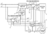
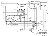
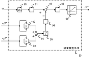
図1は本発明の実施の形態1による交流回転機の制御装置の構成を示すブロック図である。交流回転機1は同期機であって、ここでは、表面磁石型の同期機である。交流回転機1には、電圧を印加する、インバータ等の電力変換器が相当する電圧印加手段2と、交流回転機1の電流を検出する電流検出手段3と、交流回転機1の回転位置θを検出する回転位置検出器4とが接続されている。
FIG. 1 is a block diagram showing a configuration of a control device for an AC rotating machine according to
電圧印加手段2は、交流回転機1に三相電圧のU相電圧vu、V相電圧vv、W相電圧vwを印加し、電流検出手段3は、交流回転機1の三相電流のうち少なくとも二相分の電流を検出する。本実施の形態における電流検出手段3は、交流回転機1と電圧印加手段2とを結ぶ電力線からU相電流iuとV相電流ivを検出する。
なお、電流検出手段3は、図1に示すようなU相電流およびV相電流を直接検出する方法以外に、U相電流およびV相電流に加えW相電流も直接検出する方法でも良いし、公知技術である電圧印加手段2のDCリンク電流からU相電流およびV相電流を検出する方法(例えば、Y.Murai et al.,”Three−Phase Current−Waveform−Detection on PWM Inverter from DC Link Current−Steps”,Proceedings of IPEC−Yokohama 1995,pp.271−275,Yokohama,Japan,April 1995)を用いても良い。
The voltage application means 2 applies the U-phase voltage vu, the V-phase voltage vv, and the W-phase voltage vw of the three-phase voltage to the
In addition to the method of directly detecting the U-phase current and the V-phase current as shown in FIG. 1, the current detection means 3 may be a method of directly detecting the W-phase current in addition to the U-phase current and the V-phase current, A method of detecting a U-phase current and a V-phase current from a DC link current of the
微分器5は、回転位置検出器4が出力する回転位置θの変化率を演算し、交流回転機1の回転速度ωrとして出力する。座標変換手段6は、電流検出手段3から得た電流を角周波数ωrで回転する回転二軸座標(d−q軸)上の電流に座標変換する。換言すると、座標変換手段6は、電流検出手段3が出力するU相電流iu、V相電流ivから得られる三相電流を、角周波数ω(=ωr)で回転する位相でもある回転位置θに同期して回転する回転二軸座標(d−q軸)上に座標変換し、回転二軸座標(d−q軸)上の電流idおよびiqを出力する。
The
第1の電圧指令演算手段7は、後述する(3)、(4)式により、回転二軸座標(d−q軸)上の電流指令id*およびiq*と角周波数ωrとに基づいて回転二軸座標(d−q軸)上の第1の電圧指令vd1*およびvq1*を出力する。第1の電圧指令演算手段7には、交流回転機1の電気的定数の少なくとも1つ、ここでは、電機子抵抗設定値R0と電機子インダクタンス設定値L0を、定数測定手段8から得る。
The first voltage command calculating
第2の電圧指令演算手段9は、回転二軸座標(d−q軸)上の電流指令id*およびiq*と回転二軸座標(d−q軸)上の電流idおよびiqの差分電流をそれぞれ演算し、この差分電流が零に収斂するように当該差分電流に基づいて回転二軸座標(d−q軸)上の第2の電圧指令vd2*およびvq2*を出力する。
定数測定手段8は、第2の電圧指令演算手段9が出力する第2の電圧指令vd2*およびvq2*に基づいて演算した交流回転機1の電機子抵抗設定値R0と電機子インダクタンス設定値L0を第1の電圧指令演算手段7に出力する。
The second voltage command calculation means 9 calculates the difference current between the current commands id * and iq * on the rotating biaxial coordinates (dq axes) and the current id and iq on the rotating biaxial coordinates (dq axes). Each is calculated, and the second voltage commands vd2 * and vq2 * on the rotating biaxial coordinates (dq axes) are output based on the difference current so that the difference current converges to zero.
The constant measuring means 8 has an armature resistance set value R0 and an armature inductance set value L0 of the
第3の電圧指令演算手段10は、第1の電圧指令vd1*およびvq1*と第2の電圧指令vd2*およびvq2*との加算電圧を演算し、この加算電圧に基づいて回転二軸座標(d−q軸)上の第3の電圧指令vd3*およびvq3*を出力する。
電圧印加手段2は、第3の電圧指令演算手段10が出力する第3の電圧指令vd3*およびvq3*に基づいて交流回転機1に電圧を印加する。
The third voltage command calculating means 10 calculates an added voltage between the first voltage commands vd1 * and vq1 * and the second voltage commands vd2 * and vq2 *, and based on the added voltage, a rotational biaxial coordinate ( The third voltage commands vd3 * and vq3 * on the dq axis) are output.
The
第2の電圧指令演算手段9は、回転二軸座標(d−q軸)上の電流指令のd軸成分id*から回転二軸座標(d−q軸)上の電流のd軸成分idを減算して差分電流を演算する減算器11と、回転二軸座標(d−q軸)上の電流指令のq軸成分iq*から回転二軸座標(d−q軸)上の電流のq軸成分iqを減算して差分電流を演算する減算器12と、減算器11の出力を比例積分によって増幅する増幅器13と、減算器12の出力を比例積分によって増幅する増幅器14とを備える。
The second voltage command calculation means 9 calculates the d-axis component id of the current on the rotating biaxial coordinate (dq axis) from the d-axis component id * of the current command on the rotating biaxial coordinate (dq axis). A
第3の電圧指令演算手段10は、第1の電圧指令のd軸成分vd1*と第2の電圧指令のd軸成分vd2*とを加算した加算電圧を演算する加算器15と、第1の電圧指令のq軸成分vq1*と第2の電圧指令のq軸成分vq2*とを加算した加算電圧を演算する加算器16とを備え、加算器15と加算器16との出力をそれぞれ第3の電圧指令vd3*およびvq3*として出力している。
The third voltage command calculation means 10 includes an
次に、各演算手段の具体的な演算内容について説明する。この実施の形態1での交流回転機1は、表面磁石型同期機であり、回転直交座標(d−q軸)のd軸が交流回転機1の回転子磁束と一致している場合、次式が成り立つ。
Next, specific calculation contents of each calculation means will be described. The
vd=R×id−ωr×L×iq ・・・(1)
vq=R×iq+ωr×(L×id+φf) ・・・(2)
vd = R × id−ωr × L × iq (1)
vq = R × iq + ωr × (L × id + φf) (2)
但し、
vd:交流回転機1の電圧のd軸成分
vq:交流回転機1の電圧のq軸成分
R:交流回転機1の電機子抵抗
L:交流回転機1の電機子インダクタンス
φf:交流回転機1の回転子磁束振幅
However,
vd: d-axis component of voltage of
一方、第1の電圧指令演算手段7では、回転二軸座標(d−q軸)上の電流指令id*およびiq*と角周波数ωrとに基づいた(3)、(4)式によって回転二軸座標(d−q軸)上の第1の電圧指令vd1*およびvq1*を出力する。 On the other hand, in the first voltage command calculation means 7, the rotation voltage is calculated by the equations (3) and (4) based on the current commands id * and iq * on the rotation biaxial coordinates (dq axes) and the angular frequency ωr. The first voltage commands vd1 * and vq1 * on the axis coordinates (dq axes) are output.
vd1*=R0×id*−ωr×L0×iq* ・・・(3)
vq1*=R0×iq*+ωr×(L0×id*+φf0) ・・・(4)
vd1 * = R0 × id * −ωr × L0 × iq * (3)
vq1 * = R0 × iq * + ωr × (L0 × id * + φf0) (4)
但し、
φf0:交流回転機1の回転子磁束振幅設定値
ここでは、交流回転機1の回転子磁束振幅は既知であると仮定して説明する。この仮定が成り立つ場合、φf0=φfが成り立つ。なお、交流回転機1の回転子磁束振幅が未知である場合については後述する実施の形態5で説明する。
However,
φf0: Rotor magnetic flux amplitude setting value of
以上の制御系が起動した後、その動作が定常状態、ここでは、各電圧、電流がほぼ一定値、例えば、第2の電圧指令演算手段9の出力である第2の電圧指令演算値vd2*およびvq2*の絶対値が零に近い所定の範囲内になった時点では以下の動作が確認できる。
即ち、第2の電圧指令演算手段9では、減算器11の出力を比例積分によって増幅する増幅器13によって電流指令のd軸成分id*と電流のd軸成分idとが一致するとともに、減算器12の出力を比例積分によって増幅する増幅器14によって電流指令のq軸成分iq*と電流のq軸成分iqとが一致している。また、電圧印加手段2は、第3の電圧指令演算手段10が出力する第3の電圧指令vd3*およびvq3*に基づいて交流回転機1に電圧を印加しているので、交流回転機1の電圧のd軸成分vdおよびq軸成分vqは、第3の電圧指令vd3*およびvq3*に一致する。これらの関係を勘案すると(5)〜(10)式が成り立つ。
After the above control system is activated, its operation is in a steady state. Here, each voltage and current are substantially constant values, for example, the second voltage command calculation value vd2 * which is the output of the second voltage command calculation means 9 . When the absolute value of vq2 * falls within a predetermined range close to zero, the following operation can be confirmed.
That is, in the second voltage command calculation means 9, the d-axis component id * of the current command matches the d-axis component id of the current by the
vd3*=vd2*+R0×id*−ωr×L0×iq* ・・・(5)
vq3*=vq2*+R0×iq*+ωr×(L0×id*+φf0)・・・(6)
id=id* ・・・(7)
iq=iq* ・・・(8)
vd=vd3* ・・・(9)
vq=vq3* ・・・(10)
vd3 * = vd2 * + R0 × id * −ωr × L0 × iq * (5)
vq3 * = vq2 * + R0 × iq * + ωr × (L0 × id * + φf0) (6)
id = id * (7)
iq = iq * (8)
vd = vd3 * (9)
vq = vq3 * (10)
(1)〜(10)式の関係を整理すると(11)、(12)式を得る。 When the relationship between the expressions (1) to (10) is arranged, the expressions (11) and (12) are obtained.
vd2*=−(R0−R)×id*+ωr×(L0−L)×iq* ・・・(11)
vq2*=−(R0−R)×iq*−ωr×(L0−L)×id* ・・・(12)
vd2 * = − (R0−R) × id * + ωr × (L0−L) × iq * (11)
vq2 * = − (R0−R) × iq * −ωr × (L0−L) × id * (12)
この(11)、(12)式によれば、抵抗誤差(R0−R)およびインダクタンス誤差(L0−L)がない場合、vd2*およびvq2*は零であり、抵抗誤差やインダクタンス誤差が発生する場合、vd2*およびvq2*の少なくとも一方は非零となる。(11)、(12)式を整理すると(13)、(14)式を得る。 According to the equations (11) and (12), when there is no resistance error (R0-R) and inductance error (L0-L), vd2 * and vq2 * are zero, and a resistance error and an inductance error occur. In this case, at least one of vd2 * and vq2 * is non-zero. By arranging the expressions (11) and (12), the expressions (13) and (14) are obtained.
(R0−R)=−(vd2*×id*+vq2*×iq*)
÷(id*2+iq*2) ・・・(13)
(L0−L)=(vd2*×iq*−vq2*×id*)
÷{ωr×(id*2+iq*2)} ・・・(14)
(R0−R) = − (vd2 * × id * + vq2 * × iq * )
÷ (id * 2 + iq * 2 ) (13)
(L0−L) = (vd2 * × iq * −vq2 * × id * )
÷ {ωr × (id * 2 + iq * 2 )} (14)
交流回転機1の電気的定数としての電機子抵抗Rと電機子インダクタンスLを求めるため、本実施の形態1では、id*=0、iq*=(正の一定値)で与え、ωr>0である場合について考える。(13)、(14)式に、id*=0を代入すると、(15)、(16)式となる。
In order to obtain the armature resistance R and the armature inductance L as electrical constants of the
(R0−R)=−(vq2*÷iq*) ・・・(15)
(L0−L)=vd2*÷(ωr×iq*) ・・・(16)
(R0−R) = − (vq2 * ÷ iq * ) (15)
(L0−L) = vd2 * ÷ (ωr × iq * ) (16)
iq*を正の一定値で与えている場合について考えているので、(15)式右辺は「−vq2*」に比例する値となり、(16)式右辺は「vd2*÷ωr」に比例する値となる。 Since iq * is given as a positive constant value, the right side of equation (15) is proportional to “−vq2 * ”, and the right side of equation (16) is proportional to “vd2 * ÷ ωr”. Value.
(15)式から電機子抵抗について次のことが判る。
・(電機子抵抗設定値R0)>(電機子抵抗R) の場合、vq2*<0
・(電機子抵抗設定値R0)<(電機子抵抗R) の場合、vq2*>0
従って、vq2*が正の場合、電機子抵抗設定値R0を大きくすると抵抗誤差(R0−R)は零に近づき、vq2*が負の場合、電機子抵抗設定値R0を小さくすると抵抗誤差(R0−R)は零に近づく。
From the equation (15), the following can be understood for the armature resistance.
When (armature resistance set value R0)> (armature resistance R), vq2 * <0
・ If (armature resistance setting value R0) <(armature resistance R), vq2 * > 0
Therefore, when vq2 * is positive, the resistance error (R0-R) approaches zero when the armature resistance set value R0 is increased. When vq2 * is negative, the resistance error (R0) is decreased when the armature resistance set value R0 is decreased. -R) approaches zero.
同様に、(16)式から電機子インダクタンスについて次のことが判る。
・(電機子インダクタンス設定値L0)>(電機子インダクタンスL)の場合、
vd2*>0
・(電機子インダクタンス設定値L0)<(電機子インダクタンスL)の場合、
vd2*<0
従って、vd2*が正の場合、インダクタンス設定値L0を小さくするとインダクタンス誤差(L0−L)は零に近づき、vd2*が負の場合、インダクタンス設定値L0を大きくするとインダクタンス誤差(L0−L)は零に近づく。
Similarly, the following can be understood from the equation (16) for the armature inductance.
When (armature inductance set value L0)> (armature inductance L),
vd2 * > 0
When (armature inductance set value L0) <(armature inductance L),
vd2 * <0
Therefore, when vd2 * is positive, the inductance error (L0-L) approaches zero when the inductance setting value L0 is decreased, and when vd2 * is negative, the inductance error (L0-L) is increased when the inductance setting value L0 is increased. Approaching zero.
以上の関係、特に、vd2*およびvq2*の正負号と抵抗誤差およびインダクタンス誤差の増減との関係を踏まえ、定数測定手段8は、(17)、(18)式により第2の電圧指令vd2*およびvq2*に基づいて演算した交流回転機1の電機子抵抗設定値R0と電機子インダクタンス設定値L0を第1の電圧指令演算手段7に出力する。
Based on the above relationship, in particular, the relationship between the positive / negative sign of vd2 * and vq2 * and the increase / decrease in resistance error and inductance error, the constant measuring means 8 can calculate the second voltage command vd2 * by the equations (17) and (18) . And the armature resistance setting value R0 and the armature inductance setting value L0 of the
R0=kR∫(vq2*)dt ・・・(17)
L0=−kL∫(vd2*)dt ・・・(18)
但し、kR、kL:比例定数
R0 = k R ∫ (vq2 * ) dt (17)
L0 = −k L ∫ (vd2 * ) dt (18)
Where k R and k L are proportional constants
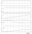
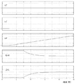
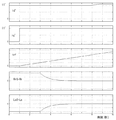
本実施の形態1における動作波形の一例を図2に示す。図において、1段目は電流指令のd軸成分id*、2段目は電流指令のq軸成分iq*、3段目は交流回転機1の角周波数ωr、4段目は抵抗誤差(R0−R)、5段目はインダクタンス誤差(L0−L)を示している。
時刻0〜1秒の期間は、停止した状態で電流指令id*およびiq*は零である。時刻1秒以降、iq*は正の一定値を保つと同時に、交流回転機1の角周波数ωrは加速して行く。定数測定手段8は、時刻3秒に到達するまでは動作を停止しており、時刻3秒に到達するとともに、(17)式により第2の電圧指令vq2*に基づいて電機子抵抗設定値R0を演算することで、R0は電機子抵抗Rに近づき抵抗誤差(R0−R)は零に収束する。
電機子インダクタンスについても、定数測定手段8は、時刻3秒に到達するとともに、(18)式により第2の電圧指令vd2*に基づいて電機子インダクタンス設定値L0を演算することで、L0は電機子インダクタンスLに近づきインダクタンス誤差(L0−L)は零に収束する。
An example of operation waveforms in the first embodiment is shown in FIG. In the figure, the first stage is the d-axis component id * of the current command, the second stage is the q-axis component iq * of the current command, the third stage is the angular frequency ωr of the
During the period from
As for the armature inductance, the constant measuring means 8 arrives at the
(11)、(12)式から分かるように、角周波数ωrが零に近い所定値より小さいと、インダクタンス誤差(L0−L)の大小に拘わらず両式の右辺第2項が零に近づき両誤差(R0−R)、(L0−L)が求められないことになる。
従って、定数測定手段8は、角周波数ωの大きさが所定値よりも大きくなる時刻3秒以降で交流回転機1の電気的定数を演算し、任意の角周波数ωの大きさが所定値よりも小さい時刻3秒以前では電気的定数の演算を停止するようにしている。これにより、角周波数ωが小さく精度よく測定できない場合、定数誤差に起因する制御性能の低下を防ぐことができる。
As can be seen from equations (11) and (12), when the angular frequency ωr is smaller than a predetermined value close to zero, the second term on the right side of both equations approaches zero regardless of the magnitude of the inductance error (L0−L). The errors (R0-R) and (L0-L) cannot be obtained.
Therefore, the constant measuring means 8 calculates the electrical constant of the
また、従来の交流回転機の制御装置では、電圧と電流と角周波数との加減乗除だけを用いて算出していたので、電圧や電流や角周波数が含んでいるノイズの影響が電機子抵抗設定値や電機子インダクタンス設定値に現れる問題があったが、本実施の形態1の(17)、(18)式による演算は電機子抵抗や電機子インダクタンスの設定値を第2の電圧指令を積分演算で得るようにしたので、電圧検出値や電流検出値のノイズが直接反映することを防ぎ、測定した定数もノイズの影響を受ける問題を解決することができる。 In addition, in the conventional AC rotating machine control device, the calculation was made using only the addition, subtraction, multiplication and division of the voltage, current, and angular frequency, so the influence of the noise included in the voltage, current, and angular frequency is the armature resistance setting. Although there is a problem that appears in the value and armature inductance setting value, the calculation by the equations (17) and (18) in the first embodiment integrates the setting value of the armature resistance and armature inductance with the second voltage command. Since it is obtained by calculation, it is possible to prevent the noise of the voltage detection value and the current detection value from being directly reflected, and to solve the problem that the measured constant is also affected by the noise.
以上のように、本実施の形態1の構成により、回転二軸座標(d−q軸)上の電流指令に回転二軸座標(d−q軸)上の電流が一致するように制御しながら交流回転機1の定数を定数測定手段8が測定することにより、第1の電圧指令演算手段7で用いる電気的定数の設定ができるという効果がある。
また、本実施の形態1では定数測定手段8が、回転二軸座標(d−q軸)上の電流指令のd軸成分の大きさを零とし、q軸成分の大きさを一定に保ったときの第2の電圧指令演算手段9が出力する第2の電圧指令に基づいて交流回転機1の電気的定数を演算するので、電機子抵抗と電機子インダクタンスといった2種類の電気的定数の測定ができるという効果がある。
また、第2の電圧指令演算手段9が出力する第2の電圧指令に基づいて演算した交流回転機1の電機子インダクタンス設定値および電機子抵抗設定値を第1の電圧指令演算手段7に出力するので、該交流回転機1の制御装置の制御精度が向上するという効果がある。
更に、電機子抵抗や電機子インダクタンスの設定値を第2の電圧指令に基づいた積分演算から得るようにしたので、電圧検出値や電流検出値のノイズが直接反映することを防ぎ、測定した定数もノイズの影響を受ける問題を解決できるという効果がある。
As described above, with the configuration of the first embodiment, control is performed so that the current on the rotating biaxial coordinates (dq axes) matches the current command on the rotating biaxial coordinates (dq axes). By measuring the constant of the
In the first embodiment, the
Further, the armature inductance set value and the armature resistance set value of the
Furthermore, since the set values of the armature resistance and the armature inductance are obtained from the integral calculation based on the second voltage command, it is possible to prevent the noise of the voltage detection value and the current detection value from being directly reflected, and to measure the constant There is also an effect that the problem affected by noise can be solved.
実施の形態2.
先の実施の形態1では、定数測定手段8は、(17)、(18)式に従い、第2の電圧指令vd2*およびvq2*に基づいて交流回転機1の電機子抵抗設定値R0と電機子インダクタンス設定値L0とを演算していたが、この実施の形態2では、第2の電圧指令vd2*およびvq2*に加え、電流指令のq軸成分iq*および角周波数ωrを用いて電機子抵抗設定値R0と電機子インダクタンス設定値L0とを演算している。
実施の形態1に比較して構成、演算は多少複雑になるが、iq*およびωrの設定が任意となるので、その分、設定値R0、L0を測定するための運転条件の自由度が高まり適用が容易になるという利点がある。
In the first embodiment, the constant measuring means 8 determines the armature resistance set value R0 of the
Although the configuration and calculation are somewhat complicated as compared to the first embodiment, since the setting of iq * and ωr is arbitrary, the degree of freedom in operating conditions for measuring the set values R0 and L0 is increased accordingly. There is an advantage that it is easy to apply.
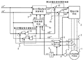
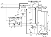
図3は、本発明の実施の形態2による構成を示すブロック図であり、定数測定手段8aは、第2の電圧指令vd2*およびvq2*に加え、電流指令のq軸成分iq*および角周波数ωrに基づいて電機子抵抗設定値R0と電機子インダクタンス設定値L0とを演算し、第1の電圧指令演算手段7にR0およびL0を出力する。なお、図3において図1と同一の符号を付したものは、同一またはこれに相当するものであり、重複する部分の個々の説明は省略する。
FIG. 3 is a block diagram showing a configuration according to the second embodiment of the present invention. The
本実施の形態2では、id*=0で与える場合を考える。先の(15)、(16)式を(19)、(20)式として再掲する。 In the second embodiment, a case where id * = 0 is considered. The previous formulas (15) and (16) are reprinted as formulas (19) and (20).
(R0−R)=−(vq2*÷iq*) ・・・(19)
(L0−L)=vd2*÷(ωr×iq*) ・・・(20)
(R0−R) = − (vq2 * ÷ iq * ) (19)
(L0−L) = vd2 * ÷ (ωr × iq * ) (20)
この(19)式右辺は−vq2*の大きさに比例し、iq*の大きさに反比例する。実施の形態1では、iq*は正の一定値としたが、本実施の形態2では、正の一定値とは限らない。この場合でも、(19)式右辺は「−(vq2*÷iq*)」に比例すると言っても良い。
また、(20)式右辺はvd2*の大きさに比例し、iq*の大きさに反比例するとともに、ωrの大きさに反比例する。換言すると、(20)式右辺は「vd2*÷(ωr×iq*)」に比例すると言っても良い。
これらを勘案し、本実施の形態2に示す定数測定手段8aは、(21)、(22)式により第2の電圧指令vd2*およびvq2*に基づいて演算した交流回転機1の電機子抵抗設定値R0と電機子インダクタンス設定値L0とを第1の電圧指令演算手段7に出力する。
The right side of the equation (19) is proportional to the magnitude of -vq2 * and inversely proportional to the magnitude of iq * . In
Further, the right side of the equation (20) is proportional to the magnitude of vd2 * , inversely proportional to the magnitude of iq * , and inversely proportional to the magnitude of ωr. In other words, it can be said that the right side of the equation (20) is proportional to “vd2 * ÷ (ωr × iq * )”.
Taking these into consideration, the constant measuring means 8a shown in the present second embodiment is configured so that the armature resistance of the
R0=kR∫(vq2*÷iq*)dt ・・・(21)
L0=−kL∫{vd2*÷(ωr×iq*)}dt ・・・(22)
但し、kR、kL:比例定数
R0 = k R ∫ (vq2 * ÷ iq * ) dt (21)
L0 = −k L ∫ {vd2 * ÷ (ωr × iq * )} dt (22)
Where k R and k L are proportional constants
実施の形態1では、iq*は正の一定値で、かつ角周波数ωrも正であるという制約が伴った。本実施の形態2では、定数測定手段8aが、(21)、(22)式を用いるので、iq*の符号やωrの符号に拘わらず、正確な電機子抵抗設定値R0と電機子インダクタンス設定値L0の演算を行うことができる。 In the first embodiment, iq * is a positive constant value and the angular frequency ωr is also positive. In the second embodiment, since the constant measuring means 8a uses the equations (21) and (22), the accurate armature resistance setting value R0 and the armature inductance setting regardless of the sign of iq * and the sign of ωr. The value L0 can be calculated.
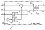
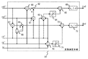
図4は、本実施の形態2における定数測定手段8aの内部構成を示す図である。図において、乗算器20は、電流指令のq軸成分iq*と角周波数ωrとの積を演算しリミッタ21に出力する。リミッタ21は、乗算器20の出力が正の場合は正の所定値以上になるようにリミット動作を行うとともに、乗算器20の出力が負の場合は負の所定値以下になるようにリミット動作を行うことによって、除算器22が零で除算しないようにする。
除算器22は、第2の電圧指令のd軸成分vd2*をリミッタ21の出力で除算し、積分器23は、除算器22の出力値を積分して−kL倍し、電機子インダクタンス設定値L0として出力する。乗算器20、リミッタ21、除算器22、積分器23による一連の演算によって前記(22)式の演算を行うことができる。
FIG. 4 is a diagram showing an internal configuration of the constant measuring means 8a in the second embodiment. In the figure, the
Divider 22, a d-axis component of the second
同様に、リミッタ24は、iq*が正の場合は正の所定値以上になるようにリミット動作を行うとともに、iq*が負の場合は負の所定値以下になるようにリミット動作を行うことによって、除算器25が零で除算しないようにする。
除算器25は、第2の電圧指令のq軸成分vq2*をリミッタ24の出力で除算し、積分器26は、除算器25の出力値を積分してkR倍し、電機子抵抗設定値R0として出力する。
Similarly, the
Divider 25, a q-axis component of the second
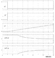
本実施の形態2における動作波形の一例を図5に示す。図において、1段目は電流指令のd軸成分id*、2段目は電流指令のq軸成分iq*、3段目は交流回転機1の角周波数ωr、4段目は抵抗誤差(R0−R)、5段目はインダクタンス誤差(L0−L)を示している。
時刻0〜1秒の期間は、停止した状態で電流指令id*およびiq*は零である。時刻1秒以降、iq*は正の一定値を保つと同時に、交流回転機1の角周波数ωrは加速して行く。定数測定手段8は、時刻3秒に到達するまでは動作を停止しており、時刻3秒に到達するとともに、(21)式により第2の電圧指令vq2*に基づいて電機子抵抗設定値R0を演算することで、R0は電機子抵抗Rに近づき抵抗誤差(R0−R)は零に収束する。
An example of operation waveforms in the second embodiment is shown in FIG. In the figure, the first stage is the d-axis component id * of the current command, the second stage is the q-axis component iq * of the current command, the third stage is the angular frequency ωr of the
During the period from
電機子インダクタンスについても、定数測定手段8は、時刻3秒に到達するとともに、(22)式により第2の電圧指令vd2*に基づいて電機子インダクタンス設定値L0を演算することで、L0は電機子インダクタンスLに近づきインダクタンス誤差(L0−L)は零に収束する。
ここで、図5を先の実施の形態1の図3と比較すると、インダクタンス誤差(L0−L)の収束性が向上している。実施の形態1では、インダクタンス設定値の演算は(18)式に基づいていたが、vd2*は角周波数ωrの大きさに比例するので、角周波数ωrが小さい場合はインダクタンス誤差(L0−L)があってもvd2*の値も小さく、インダクタンス誤差(L0−L)の収束性が悪かった。
本実施の形態2では(22)式に基づいてインダクタンス設定値の演算を行うようにしたので、インダクタンス誤差(L0−L)の収束性が向上した。同様に、iq*の大きさが変化する場合でも本実施の形態2に示した定数測定手段8aを用いればiq*の大きさに拘わらず抵抗誤差(R0−R)およびインダクタンス誤差(L0−L)の収束性を一定に保つことができ、適切な比例定数kR、kLを与えることによってそれぞれの収束性を向上させることができる。
As for the armature inductance, the constant measuring means 8 arrives at
Here, when FIG. 5 is compared with FIG. 3 of the first embodiment, the convergence of the inductance error (L0-L) is improved. In the first embodiment, the calculation of the inductance setting value is based on the equation (18). However, since vd2 * is proportional to the magnitude of the angular frequency ωr, the inductance error (L0−L) is small when the angular frequency ωr is small. However, the value of vd2 * was small, and the convergence of the inductance error (L0-L) was poor.
In the second embodiment, since the inductance set value is calculated based on the equation (22), the convergence of the inductance error (L0-L) is improved. Similarly, even when the magnitude of iq * changes, if the constant measuring means 8a shown in the second embodiment is used, the resistance error (R0-R) and the inductance error (L0-L) regardless of the magnitude of iq *. ) Can be kept constant, and by providing appropriate proportionality constants k R and k L , the respective convergence can be improved.
以上のように、本実施の形態2では、定数測定手段8aは、第2の電圧指令vd2*、vq2*、電流指令のq軸成分iq*および角周波数ωrに基づいて電機子抵抗設定値R0と電機子インダクタンス設定値L0とを演算するようにしたので、電流指令のq軸成分iq*および角周波数ωrの符号や大きさに拘わらず、正確な電機子抵抗設定値および電機子インダクタンス設定値を得られるという効果がある。
また、電機子抵抗設定値および電機子インダクタンス設定値は、第2の電圧指令を電流指令で除算するようにしたので、電流指令の大きさに拘わらず抵抗誤差(R0−R)の収束性およびインダクタンス誤差(L0−L)の収束性が向上するという効果がある。
また、電機子インダクタンス設定値については、第2の電圧指令vd2*を角周波数ωrで除算した値に基づいて演算するようにしたので、角周波数ωrに拘わらずインダクタンス誤差(L0−L)の収束性が向上するという効果がある。
As described above, in the second embodiment, the
Further, since the armature resistance setting value and the armature inductance setting value are obtained by dividing the second voltage command by the current command, the convergence property of the resistance error (R0-R) regardless of the magnitude of the current command and There is an effect that the convergence of the inductance error (L0-L) is improved.
Further, the armature inductance set value is calculated based on the value obtained by dividing the second voltage command vd2 * by the angular frequency ωr, so that the convergence of the inductance error (L0−L) is achieved regardless of the angular frequency ωr. This has the effect of improving the performance.
実施の形態3.
先の実施の形態1、2における交流回転機1は同期機であって、特に、表面磁石型の同期機の場合を扱った。本実施の形態3では、交流回転機1bは同期機であって、特に、埋め込み磁石型の同期機の場合について説明する。埋め込み磁石型同期機は、永久磁石を埋め込むため回転子の磁気回路形状が軸対称ではなく、いわゆる突極性を有するものとなる。
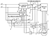
図6は、本発明の実施の形態3による構成を示すブロック図であり、交流回転機1bは同期機であって、埋め込み磁石型の同期機である。定数測定手段8bは、交流回転機1bの電機子インダクタンスのd軸成分設定値Ld0および交流回転機1bの電機子インダクタンスのq軸成分設定値Lq0を演算し、第1の電圧指令演算手段7bにLd0およびLq0を出力する。なお、図6において、図1と同一の符号を付したものは、同一またはこれに相当し、重複する部分の個々の説明は省略する。
The
FIG. 6 is a block diagram showing a configuration according to the third embodiment of the present invention. The
交流回転機1bは、埋め込み磁石型同期機であり、回転直交座標(d−q軸)のd軸が交流回転機1の回転子磁束と一致している場合、次式が成り立つ。
The
vd=R×id−ωr×Lq×iq ・・・(23)
vq=R×iq+ωr×(Ld×id+φf) ・・・(24)
vd = R × id−ωr × Lq × iq (23)
vq = R × iq + ωr × (Ld × id + φf) (24)
但し、
Ld:交流回転機1の電機子インダクタンスのd軸成分
Lq:交流回転機1の電機子インダクタンスのq軸成分
一方、第1の電圧指令演算手段7bでは、回転二軸座標(d−q軸)上の電流指令id*およびiq*と角周波数ωrに基づいた(25)、(26)式によって回転二軸座標(d−q軸)上の第1の電圧指令vd1*およびvq1*を出力する。
However,
Ld: d-axis component of the armature inductance of the
vd1*=R0×id*−ωr×Lq0×iq* ・・・(25)
vq1*=R0×iq*+ωr×(Ld0×id*+φf0) ・・・(26)
vd1 * = R0 × id * −ωr × Lq0 × iq * (25)
vq1 * = R0 × iq * + ωr × (Ld0 × id * + φf0) (26)
ここでは、交流回転機1bの回転子磁束振幅および電機子抵抗は既知であるとし、φf0=φfおよびR0=Rが成り立っている場合について説明する。
先の実施の形態1の場合と同様、動作が定常状態で、第2の電圧指令演算手段9の出力である第2の電圧指令演算値vd2*およびvq2*の絶対値が零に近い所定の範囲内になった時点では以下の動作が確認できる。
Here, it is assumed that the rotor magnetic flux amplitude and the armature resistance of the
As in the case of the first embodiment, the operation is in a steady state and the absolute values of the second voltage command calculation values vd2 * and vq2 * , which are the outputs of the second voltage command calculation means 9, are close to zero. When it falls within the range, the following operations can be confirmed.
即ち、第2の電圧指令演算手段9では、電流指令のd軸成分id*と電流のd軸成分idとが一致するとともに、電流指令のq軸成分iq*と電流のq軸成分iqとが一致している。また、電圧印加手段2は、第3の電圧指令演算手段10が出力する第3の電圧指令vd3*およびvq3*に基づいて交流回転機1に電圧を印加しているので、交流回転機1bの電圧のd軸成分vdおよびq軸成分vqは第3の電圧指令vd3*およびvq3*に一致する。これらの関係を勘案すると(27)〜(32)式が成り立つ。
That is, in the second voltage command calculation means 9, the d-axis component id * of the current command matches the d-axis component id of the current, and the q-axis component iq * of the current command and the q-axis component iq of the current Match. Moreover, since the voltage application means 2 is applying the voltage to the
vd3*=vd2*+R0×id*−ωr×Lq0×iq* ・・・(27)
vq3*=vq2*+R0×iq*+ωr×(Ld0×id*+φf0)・・・(28)
id=id* ・・・(29)
iq=iq* ・・・(30)
vd=vd3* ・・・(31)
vq=vq3* ・・・(32)
vd3 * = vd2 * + R0 × id * −ωr × Lq0 × iq * (27)
vq3 * = vq2 * + R0 × iq * + ωr × (Ld0 × id * + φf0) (28)
id = id * (29)
iq = iq * (30)
vd = vd3 * (31)
vq = vq3 * (32)
以上の関係式を整理すると(33)、(34)式を得る。 By arranging the above relational expressions, the following expressions (33) and (34) are obtained.
vd2*= ωr×(Lq0−Lq)×iq* ・・・(33)
vq2*=−ωr×(Ld0−Ld)×id* ・・・(34)
vd2 * = ωr × (Lq0−Lq) × iq * (33)
vq2 * = − ωr × (Ld0−Ld) × id * (34)
この(33)、(34)式によれば、d軸インダクタンス誤差(Ld0−Ld)およびq軸インダクタンス誤差(Lq0−Lq)がない場合、vd2*およびvq2*は零であり、d軸インダクタンス誤差やq軸インダクタンス誤差が発生する場合、vd2*およびvq2*の少なくとも一方は非零となる。(33)、(34)式を整理すると(35)、(36)式を得る。 According to the equations (33) and (34), when there is no d-axis inductance error (Ld0-Ld) and q-axis inductance error (Lq0-Lq), vd2 * and vq2 * are zero, and d-axis inductance error When q-axis inductance error occurs, at least one of vd2 * and vq2 * is non-zero. By arranging the equations (33) and (34), the equations (35) and (36) are obtained.
(Ld0−Ld)=−vq2*÷(ωr×id*) ・・・(35)
(Lq0−Lq)= vd2*÷(ωr×iq*) ・・・(36)
(Ld0−Ld) = − vq2 * ÷ (ωr × id * ) (35)
(Lq0−Lq) = vd2 * ÷ (ωr × iq * ) (36)
本実施の形態3では、id*を負の一定値、iq*=−id*でそれぞれ与え、ωr>0である場合について考える。
(35)式から、電機子インダクタンスのd軸成分について次のことが判る。
In the third embodiment, id * a negative constant value, iq * = -id * in given respectively, consider the case a .omega.r> 0.
From the equation (35), the following can be understood for the d-axis component of the armature inductance.
・(Ld0)>(Ld) の場合、vq2*>0
・(Ld0)<(Ld) の場合、vq2*<0
・ If (Ld0)> (Ld), vq2 * > 0
If (Ld0) <(Ld), vq2 * <0
従って、vq2*が正の場合、電機子インダクタンスのd軸成分設定値Ld0を小さくするとd軸インダクタンス誤差(Ld0−Ld)は零に近づき、vq2*が負の場合、電機子インダクタンスのd軸成分設定値Ld0を大きくするとd軸インダクタンス誤差(Ld0−Ld)は零に近づく。
同様に、(36)式から電機子インダクタンスのq軸成分について次のことが判る。
Therefore, when vq2 * is positive, the d-axis inductance error (Ld0-Ld) approaches zero when the d-axis component set value Ld0 of the armature inductance is reduced, and when vq2 * is negative, the d-axis component of the armature inductance When the set value Ld0 is increased, the d-axis inductance error (Ld0−Ld) approaches zero.
Similarly, the following can be understood from the q-axis component of the armature inductance from the equation (36).
・(Lq0)>(Lq) の場合、vd2*>0
・(Lq0)<(Lq) の場合、vd2*<0
-When (Lq0)> (Lq), vd2 * > 0
If (Lq0) <(Lq), vd2 * <0
従って、vd2*が正の場合、Lq0を小さくするとq軸インダクタンス誤差(Lq0−Lq)は零に近づき、vd2*が負の場合、Lq0を大きくするとq軸インダクタンス誤差(Lq0−Lq)は零に近づく。 Therefore, when vd2 * is positive, if Lq0 is decreased, the q-axis inductance error (Lq0-Lq) approaches zero. When vd2 * is negative, increasing Lq0 causes the q-axis inductance error (Lq0-Lq) to be zero. Get closer.
以上の関係を用いて定数測定手段8bは、(37)、(38)式に基づいて第2の電圧指令vd2*およびvq2*に基づいて演算した交流回転機の電機子インダクタンス設定値のd軸成分Ld0およびq軸成分Lq0を第1の電圧指令演算手段7bに出力する。 Using the above relation, the constant measuring means 8b uses the d-axis of the armature inductance set value of the AC rotating machine calculated based on the second voltage commands vd2 * and vq2 * based on the equations (37) and (38). The component Ld0 and the q-axis component Lq0 are output to the first voltage command calculation means 7b.
Ld0=−kLd∫(vq2*)dt ・・・(37)
Lq0=−kLq∫(vd2*)dt ・・・(38)
但し、kLd、kLq:比例定数
Ld0 = −k Ld ∫ (vq2 * ) dt (37)
Lq0 = −k Lq ∫ (vd2 * ) dt (38)
However, k Ld, k Lq : proportionality constant
本実施の形態3における動作波形の一例を図7に示す。図において、1段目は電流指令のd軸成分id*、2段目は電流指令のq軸成分iq*、3段目は交流回転機1の角周波数ωr、4段目はd軸インダクタンス誤差(Ld0−Ld)、5段目はq軸インダクタンス誤差(Lq0−Lq)を示している。
時刻0〜1秒の期間は、停止した状態で電流指令id*およびiq*は零である。時刻1秒以降、id*は負の一定値を保つと同時にiq*は正の一定値を保ち、交流回転機1bの角周波数ωrは発生したトルクによって加速して行く。定数測定手段8bは、時刻3秒に到達するまでは動作を停止しており、時刻3秒に到達すると、第2の電圧指令vq2*に基づいて電機子インダクタンス設定値のd軸成分Ld0を演算することで、Ld0は電機子インダクタンスのd軸成分Ldに近づき抵抗誤差(Ld0−L)は零に収束する。
電機子インダクタンスのq軸成分についても、定数測定手段8bは、時刻3秒に到達すると、第2の電圧指令vd2*に基づいて電機子インダクタンス設定値のq軸成分Lq0を演算することで、Lq0は電機子インダクタンスのq軸成分Lqに近づきq軸インダクタンス誤差(Lq0−Lq)は零に収束する。
An example of the operation waveform in the third embodiment is shown in FIG. In the figure, the first stage is the d-axis component id * of the current command, the second stage is the q-axis component iq * of the current command, the third stage is the angular frequency ωr of the
During the period from
Regarding the q-axis component of the armature inductance, the
以上のように、本実施の形態3では、定数測定手段8bが、回転二軸座標(d−q軸)上の電流指令のd軸成分を負の一定値を保つとともに電流指令のq軸成分を正の一定値に保ち、第2の電圧指令演算手段9が出力する第2の電圧指令に基づいて交流回転機1bの電気的定数を演算するので、電機子インダクタンスのd軸成分およびq軸成分といった2種類の電気的定数の測定ができるという効果がある。
また、交流回転機1bは突極性を有する同期機であって、第2の電圧指令演算手段9が出力する第2の電圧指令のd軸成分に基づいて演算した交流回転機1bのq軸インダクタンス値および第2の電圧指令のq軸成分に基づいて演算した交流回転機1bのd軸インダクタンス値を第1の電圧指令演算手段7bに出力するので、突極性を有する同期機のd軸インダクタンス値およびq軸インダクタンス値を定数測定手段8bが測定し、第1の電圧指令演算手段7bの電気的定数として設定することができるという効果を得る。
As described above, in the third embodiment, the
The
実施の形態4.
先の実施の形態3では、定数測定手段8bは、(37)、(38)式に従い、第2の電圧指令vd2*およびvq2*に基づいて交流回転機1bの電機子インダクタンス設定値のd軸成分Ld0およびq軸成分Lq0を演算していたが、第2の電圧指令vd2*、vq2*、電流指令のd軸成分id*、q軸成分iq*、および角周波数ωrに基づいて電機子インダクタンス設定値のd軸成分Ld0およびq軸成分Lq0を演算しても良い。
Embodiment 4 FIG.
In the previous third embodiment, the constant measuring means 8b is configured so that the d-axis of the armature inductance set value of the
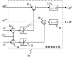
図8は、本発明の実施の形態4による構成を示すブロック図であり、ここでは、定数測定手段8cは、電機子インダクタンスのd軸成分設定値Ld0および電機子インダクタンスのq軸成分設定値Lq0を演算していたが、第2の電圧指令vd2*、vq2*、電流指令id*、iq*および角周波数ωrに基づいて電機子インダクタンスのd軸成分設定値Ld0および電機子インダクタンスのq軸成分設定値Lq0を演算し、第1の電圧指令演算手段7bにLd0およびLq0を出力する。なお、図8において、図6と同一の符号を付したものは、同一またはこれに相当するものであり、重複する部分の個々の説明は省略する。 FIG. 8 is a block diagram showing a configuration according to the fourth embodiment of the present invention. Here, the constant measuring means 8c includes the armature inductance d-axis component set value Ld0 and the armature inductance q-axis component set value Lq0. Is calculated based on the second voltage command vd2 * , vq2 * , current command id * , iq *, and angular frequency ωr, and the armature inductance d-axis component set value Ld0 and the armature inductance q-axis component. The set value Lq0 is calculated, and Ld0 and Lq0 are output to the first voltage command calculation means 7b. In FIG. 8, the same reference numerals as those in FIG. 6 denote the same or corresponding parts, and the description of the overlapping parts is omitted.
先の(35)、(36)式を(39)、(40)式として再掲する。 The previous formulas (35) and (36) are reprinted as formulas (39) and (40).
(Ld0−Ld)=−vq2*÷(ωr×id*) ・・・(39)
(Lq0−Lq)= vd2*÷(ωr×iq*) ・・・(40)
(Ld0−Ld) = − vq2 * ÷ (ωr × id * ) (39)
(Lq0−Lq) = vd2 * ÷ (ωr × iq * ) (40)
この(39)式右辺は、−vq2*の大きさに比例し、id*の大きさに反比例するとともに、ωrの大きさに反比例する。また、(40)式右辺は、vd2*の大きさに比例し、iq*の大きさに反比例するとともに、ωrの大きさに反比例する。これらを勘案し、本実施の形態4に示す定数測定手段8cは、(41)、(42)式を利用し、第2の電圧指令vd2*およびvq2*に基づいて演算した電機子インダクタンスのd軸成分設定値Ld0および電機子インダクタンスのq軸成分設定値Lq0を第1の電圧指令演算手段7bに出力する。 The right side of the equation (39) is proportional to the magnitude of −vq2 * , inversely proportional to the magnitude of id * , and inversely proportional to the magnitude of ωr. Further, the right side of the equation (40) is proportional to the magnitude of vd2 * , inversely proportional to the magnitude of iq * , and inversely proportional to the magnitude of ωr. Taking these into consideration, the constant measuring means 8c shown in the fourth embodiment uses the equations (41) and (42) to calculate the armature inductance d calculated based on the second voltage commands vd2 * and vq2 *. The shaft component set value Ld0 and the armature inductance q-axis component set value Lq0 are output to the first voltage command calculating means 7b.
Ld0=−kLd∫{vq2*÷(ωr×id*)}dt ・・・(41)
Lq0= kLq∫{vd2*÷(ωr×iq*)}dt ・・・(42)
但し、kLd、kLq:比例定数
Ld0 = −k Ld ∫ {vq2 * ÷ (ωr × id * )} dt (41)
Lq0 = k Lq ∫ {vd2 * ÷ (ωr × iq *)} dt ··· (42)
Where k Ld and k Lq are proportional constants
先の実施の形態3では、id*を負の一定値、iq*=−id*でそれぞれ与え、かつ、角周波数ωrも正であるという制約が伴った。これに対し、本実施の形態4では、定数測定手段8cが(41)、(42)式を用いるので、id*、iq*の符号やωrの符号に拘わらず、正確な電機子インダクタンスのd軸成分設定値Ld0および電機子インダクタンスのq軸成分設定値Lq0の演算を行うことができる。
In the
図9は、本実施の形態4における定数測定手段8cの内部構成を示す図である。図において、乗算器30は、電流指令のq軸成分iq*と角周波数ωrとの積を演算しリミッタ31に出力する。リミッタ31は、乗算器30の出力が正の場合は正の所定値以上になるようにリミット動作を行うとともに、乗算器30の出力が負の場合は負の所定値以下になるようにリミット動作を行うことによって、除算器32が零で除算しないようにする。
除算器32は、第2の電圧指令のd軸成分vd2*をリミッタ31の出力で除算し、積分器33は、除算器32の値を積分してkLq倍し、電機子インダクタンス設定値のq軸成分Lq0として出力する。乗算器30、リミッタ31、除算器32、積分器33による一連の演算によって(42)式の演算を行うことができる。
FIG. 9 is a diagram showing an internal configuration of the constant measuring means 8c in the fourth embodiment. In the figure, the
Divider 32, a d-axis component of the second
同様に、乗算器34は、電流指令のd軸成分id*と角周波数ωrとの積を演算しリミッタ35に出力する。リミッタ35は、乗算器34の出力が正の場合は正の所定値以上になるようにリミット動作を行うとともに、乗算器34の出力が負の場合は負の所定値以下になるようにリミット動作を行うことによって、除算器36が零で除算しないようにする。
除算器36は、第2の電圧指令のq軸成分vq2*をリミッタ35の出力で除算し、積分器37は、除算器36の値を積分してkLd倍し、電機子インダクタンス設定値のd軸成分Ld0として出力する。乗算器34、リミッタ35、除算器36、積分器37による一連の演算によって(41)式の演算を行うことができる。
Similarly, the
The
以上のように、本実施の形態4では、定数測定手段8cは、第2の電圧指令vd2*、vq2*、電流指令のid*、iq*および角周波数ωrに基づいて電機子インダクタンスのd軸成分設定値Ld0および電機子インダクタンスのq軸成分設定値Lq0を演算するようにしたので、電流指令id*、iq*および角周波数ωrの符号や大きさに拘わらず、正確な電機子インダクタンス設定値を得るという効果がある。
As described above, in the fourth embodiment, the
また、電機子インダクタンス設定値は、第2の電圧指令を電流指令で除算するようにしたので、電流指令の大きさに拘わらずd軸インダクタンス誤差(Ld0−Ld)およびq軸インダクタンス誤差(Lq0−Lq)の収束性が向上するという効果がある。
また、第2の電圧指令vd2*を角周波数ωrで除算した値に基づいて演算するようにしたので、角周波数ωrに拘わらずd軸インダクタンス誤差(Ld0−Ld)およびq軸インダクタンス誤差(Lq0−Lq)の収束性が向上するという効果がある。
Further, since the armature inductance set value is obtained by dividing the second voltage command by the current command, the d-axis inductance error (Ld0−Ld) and the q-axis inductance error (Lq0− There is an effect that the convergence of Lq) is improved.
Further, since the second voltage command vd2 * is calculated based on a value obtained by dividing by the angular frequency ωr, the d-axis inductance error (Ld0−Ld) and the q-axis inductance error (Lq0− There is an effect that the convergence of Lq) is improved.
実施の形態5.
先の実施の形態例では、回転子磁束の振幅および位相は既知である場合について説明した。
即ち、回転子磁束の振幅が既知である場合とは、回転子磁束に関して、φf0=φfが成り立っている場合を指す。交流回転機単体試験などで回転機の誘起電圧定数を予め得ている場合などが該当する。
また、回転子磁束の位相が既知である場合とは、位置センサの絶対位置と回転子磁束との関係が一意に定まっている場合を指す。具体例としては、エンコーダなどの位置センサを取り付けるときに回転子磁束の位相を考慮して取り付け作業を行ったり、エンコーダ取り付け後に回転機単体試験などで誘起電圧と回転位置の関係を予め得ている場合などが該当する。
In the previous embodiment, the case where the amplitude and phase of the rotor magnetic flux are known has been described.
That is, the case where the amplitude of the rotor magnetic flux is known refers to the case where φf0 = φf holds for the rotor magnetic flux. This corresponds to the case where the induced voltage constant of the rotating machine is obtained in advance in an AC rotating machine unit test or the like.
The case where the phase of the rotor magnetic flux is known refers to the case where the relationship between the absolute position of the position sensor and the rotor magnetic flux is uniquely determined. As a specific example, when a position sensor such as an encoder is attached, the attachment is performed in consideration of the phase of the rotor magnetic flux, or the relationship between the induced voltage and the rotational position is obtained in advance by a rotating machine unit test after the encoder is attached. This is the case.
回転子磁束の振幅が既知でない場合として、機械に組み込まれた既設回転機のような回転機単体試験などができないような場合がある。また、回転子磁束の位相が既知でない場合としては、エンコーダなどの位置センサの0度と回転子磁束が一致していない場合がある。回転子磁束の振幅や位相が既知でない場合、例えば、先の実施の形態1では、回転子磁束の振幅と位相が既知である必要があるので、本実施の形態5によってこれらを既知にすることで、実施の形態1への展開ができる利点がある。
本実施の形態5では、交流回転機1bは同期機であって、特に、回転子磁束の振幅および位相が不明の場合について説明する。
As a case where the amplitude of the rotor magnetic flux is not known, there may be a case where a rotating machine unit test such as an existing rotating machine incorporated in a machine cannot be performed. Further, when the phase of the rotor magnetic flux is not known, there is a case where the rotor magnetic flux does not coincide with 0 degree of a position sensor such as an encoder. If the amplitude and phase of the rotor magnetic flux are not known, for example, in the first embodiment, since the amplitude and phase of the rotor magnetic flux must be known, these are made known by the fifth embodiment. Thus, there is an advantage that it can be expanded to the first embodiment.
In the fifth embodiment, the
図10は、本発明の実施の形態5による構成を示すブロック図であり、定数測定手段8dは、交流回転機1bの磁束振幅設定値φf0および回転直交座標(d−q軸)のd軸と交流回転機1bの回転子磁束との位相差Δθを演算し、第1の電圧指令演算手段7bにφfを出力するとともに、減算器40に位相差Δθを出力する。なお、図6と同一の符号を付したものは、同一またはこれに相当するものであり、重複する部分の個々の説明は省略する。
FIG. 10 is a block diagram showing a configuration according to the fifth embodiment of the present invention. The constant measuring means 8d includes a magnetic flux amplitude set value φf0 of the
交流回転機1bは、埋め込み磁石型同期機であり、回転直交座標(d−q軸)のd軸が交流回転機1bの回転子磁束との間に位相差Δθがある場合、次式が成り立つ。
The
vd=R×id−ωr×(Lq×iq−φf×sinΔθ) ・・・(43)
vq=R×iq+ωr×(Ld×id+φf×cosΔθ) ・・・(44)
vd = R × id−ωr × (Lq × iq−φf × sin Δθ) (43)
vq = R × iq + ωr × (Ld × id + φf × cos Δθ) (44)
一方、第1の電圧指令演算手段7bでは、回転二軸座標(d−q軸)上の電流指令id*およびiq*と角周波数ωrに基づいた(25)、(26)式によって回転二軸座標(d−q軸)上の第1の電圧指令vd1*およびvq1*を出力する。(25)、(26)式を(45)、(46)式として再掲する。 On the other hand, in the first voltage command calculation means 7b, the rotation biaxial is expressed by the equations (25) and (26) based on the current commands id * and iq * on the rotation biaxial coordinates (dq axes) and the angular frequency ωr. The first voltage commands vd1 * and vq1 * on the coordinates (dq axes) are output. Expressions (25) and (26) are re-displayed as expressions (45) and (46).
vd1*=R0×id*−ωr×Lq0×iq* ・・・(45)
vq1*=R0×iq*+ωr×(Ld0×id*+φf0) ・・・(46)
vd1 * = R0 × id * −ωr × Lq0 × iq * (45)
vq1 * = R0 × iq * + ωr × (Ld0 × id * + φf0) (46)
先の実施の形態1の場合と同様、動作が定常状態で、第2の電圧指令演算手段9の出力である第2の電圧指令演算値vd2*およびvq2*の絶対値が零に近い所定の範囲内になった時点では以下の動作が確認できる。
即ち、第2の電圧指令演算手段9では、電流指令のd軸成分id*と電流のd軸成分idとが一致するとともに、電流指令のq軸成分iq*と電流のq軸成分iqとが一致している。また、電圧印加手段2は、第3の電圧指令演算手段10が出力する第3の電圧指令vd3*およびvq3*に基づいて交流回転機1bに電圧を印加しているので、交流回転機1bの電圧のd軸成分vdおよびq軸成分vqは、第3の電圧指令vd3*およびvq3*に一致する。これらの関係を勘案すると(47)〜(52)式が成り立つ。
As in the case of the first embodiment, the operation is in a steady state and the absolute values of the second voltage command calculation values vd2 * and vq2 * , which are the outputs of the second voltage command calculation means 9, are close to zero. When it falls within the range, the following operations can be confirmed.
That is, in the second voltage command calculation means 9, the d-axis component id * of the current command matches the d-axis component id of the current, and the q-axis component iq * of the current command and the q-axis component iq of the current Match. Moreover, since the voltage application means 2 is applying the voltage to the
vd3*=vd2*+R0×id*−ωr×Lq0×iq* ・・・(47)
vq3*=vq2*+R0×iq*+ωr×(Ld0×id*+φf0)
・・・(48)
id=id* ・・・(49)
iq=iq* ・・・(50)
vd=vd3* ・・・(51)
vq=vq3* ・・・(52)
vd3 * = vd2 * + R0 × id * −ωr × Lq0 × iq * (47)
vq3 * = vq2 * + R0 × iq * + ωr × (Ld0 × id * + φf0)
... (48)
id = id * (49)
iq = iq * (50)
vd = vd3 * (51)
vq = vq3 * (52)
(43)〜(52)式の関係を整理すると(53)、(54)式を得る。 If the relationship between the equations (43) to (52) is arranged, equations (53) and (54) are obtained.
vd2*=−(R0−R)×id*+ωr×(Lq0−Lq)×iq*
−ωr×φf×sinΔθ ・・・(53)
vq2*=−ωr×(Ld0−Ld)×id*−(R0−R)×iq*
−ωr×(φf0+φf×cosΔθ) ・・・(54)
vd2 * = − (R0−R) × id * + ωr × (Lq0−Lq) × iq *
−ωr × φf × sin Δθ (53)
vq2 * = − ωr × (Ld0−Ld) × id * − (R0−R) × iq *
−ωr × (φf0 + φf × cosΔθ) (54)
ここでは、電流指令をid*=iq*=0で与える。なお、後段の図11による動作の説明で触れるが、具体的には、交流回転機1bを何らかの方法で回転させた後に、id*=iq*=0と設定し、回転子磁束の振幅と位相を測定することになる。
この場合、(53)、(54)式は(55)、(56)式となる。
Here, the current command is given by id * = iq * = 0. As will be described later with reference to FIG. 11, specifically, after rotating the
In this case, equations (53) and (54) become equations (55) and (56).
vd2*=−φf×sinΔθ ・・・(55)
vq2*=−φf0+φf×cosΔθ ・・・(56)
vd2 * = − φf × sin Δθ (55)
vq2 * = − φf0 + φf × cosΔθ (56)
この(55)、(56)式によれば、位相差Δθおよび磁束誤差(φf0−φf)がない場合、vd2*およびvq2*は零であり、位相差Δθまたは磁束誤差(φf0−φf)が発生する場合、vd2*またはvq2*の少なくとも一方は非零となる。
sinΔθ≒Δθ、cosΔθ≒1とし、(55)、(56)式を整理すると(57)、(58)式を得る。
According to the equations (55) and (56), when there is no phase difference Δθ and magnetic flux error (φf0−φf), vd2 * and vq2 * are zero, and the phase difference Δθ or magnetic flux error (φf0−φf) is If it occurs, at least one of vd2 * or vq2 * is non-zero.
When sin Δθ≈Δθ and cos Δθ≈1, and formulas (55) and (56) are arranged, formulas (57) and (58) are obtained.
Δθ=−vd2*÷φf ・・・(57)
(φf0−φf)=−vq2* ・・・(58)
Δθ = −vd2 * ÷ φf (57)
(Φf0−φf) = − vq2 * (58)
(57)式から位相差Δθについて次のことが判る。 From the equation (57), the following can be understood for the phase difference Δθ.
・(回転直交座標のd軸位相)>(回転子磁束の位相) の場合、vd2*<0
・(回転直交座標のd軸位相)<(回転子磁束の位相) の場合、vd2*>0
When (d-axis phase of rotation orthogonal coordinates)> (rotor magnetic flux phase), vd2 * <0
・ If (d-axis phase of rotation orthogonal coordinates) <(phase of rotor magnetic flux), vd2 * > 0
従って、vd2*が正の場合、回転直交座標のd軸位相を大きくすると位相差Δθは零に近づき、vd2*が負の場合、回転直交座標のd軸位相を小さくすると位相差Δθは零に近づく。
同様に、上記(58)式から回転子磁束の振幅について次のことが判る。
Therefore, when vd2 * is positive, the phase difference Δθ approaches zero when the d-axis phase of the rotation orthogonal coordinate is increased, and when vd2 * is negative, when the d-axis phase of the rotation orthogonal coordinate is decreased, the phase difference Δθ becomes zero. Get closer.
Similarly, the following can be understood from the above equation (58) with respect to the amplitude of the rotor magnetic flux.
・(φf0)>(φf) の場合、vq2*<0
・(φf0)<(φf) の場合、vq2*>0
When (φf0)> (φf), vq2 * <0
・ If (φf0) <(φf), vq2 * > 0
従って、vq2*が正の場合、φf0を大きくすると磁束振幅誤差(φf0−φf)は零に近づき、vd2*が負の場合、φf0を小さくすると磁束振幅誤差(φf0−φf)は零に近づく。 Therefore, when vq2 * is positive, increasing φf0 causes the magnetic flux amplitude error (φf0−φf) to approach zero, and when vd2 * is negative, decreasing φf0 causes the magnetic flux amplitude error (φf0−φf) to approach zero.
以上の関係を用いて定数測定手段8dは、(59)、(60)式により第2の電圧指令vd2*およびvq2*に基づいて演算した位相差Δθを回転位置検出器4が出力する回転位置θに加算し、また、磁束振幅設定値φf0を第1の電圧指令演算手段7bに出力する。 Using the above relationship, the constant measuring means 8d uses the equations (59) and (60) to calculate the rotational position at which the rotational position detector 4 outputs the phase difference Δθ calculated based on the second voltage commands vd2 * and vq2 *. The magnetic flux amplitude set value φf0 is output to the first voltage command calculating means 7b.
Δθ=kθ∫(vd2*)dt ・・・(59)
φf0=−kφ∫(vq2*)dt ・・・(60)
但し、kθ、kφ:比例定数
Δθ = k θ ∫ (vd2 * ) dt (59)
φf0 = -k φ ∫ (vq2 * ) dt ··· (60)
Where k θ and k φ are proportional constants
以上のように、本実施の形態5では、定数測定手段8dが、回転二軸座標(d−q軸)上の電流指令のd軸成分およびq軸成分を一定値に保ち、第2の電圧指令演算手段9が出力する第2の電圧指令に基づいて交流回転機1bの電気的定数を演算するので、位相差Δθおよび磁束振幅設定値φf0といった2種類の電気的定数の測定ができるという効果がある。
As described above, in the fifth embodiment, the
本実施の形態5における動作波形の一例を図11に示す。図において、1段目は電流指令のd軸成分id*、2段目は電流指令のq軸成分iq*、3段目は交流回転機1bの角周波数ωr、4段目は位相差Δθ、5段目は磁束振幅誤差(φf0−φf)を示している。
時刻0〜1秒の期間は、停止した状態で電流指令id*およびiq*は零である。時刻1秒以降、id*は零を保つと同時にiq*は正の一定値を保ち、交流回転機1bの角周波数ωrは発生したトルクによって加速して行く。定数測定手段8dは、時刻6秒に到達するまでは動作を停止しておく。時刻6秒に到達すると、id*およびiq*は零を保ち、定数測定手段8dは、第2の電圧指令vd2*およびvq2*に基づいて位相差Δθおよび磁束振幅設定値φf0を演算することで、位相差Δθおよび磁束振幅誤差(φf0−φf)は零に収束する。
id*=iq*=0の条件を満足させておけば、RやLに起因する電圧降下が発生しないので、RやLが未知であってもφf0やΔθを得ることが可能となる。
An example of operation waveforms in the fifth embodiment is shown in FIG. In the figure, the first stage is the d-axis component id * of the current command, the second stage is the q-axis component iq * of the current command, the third stage is the angular frequency ωr of the
During the period from
If the condition of id * = iq * = 0 is satisfied, a voltage drop due to R and L does not occur, so that φf0 and Δθ can be obtained even if R and L are unknown.
以上のように、本実施の形態5では、定数測定手段8dが、回転二軸座標(d−q軸)上の電流指令を零に保ち、第2の電圧指令演算手段9が出力する第2の電圧指令に基づいて交流回転機1bの電気的定数を演算するので、位相差Δθおよび磁束振幅設定値φf0といった2種類の電気的定数の測定ができるという効果がある。
As described above, in the fifth embodiment, the
実施の形態6.
先の各実施の形態における交流回転機は、同期機を扱った。本実施の形態6においては、交流回転機1eが誘導機である場合について説明する。
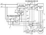
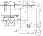
図12は、本発明の実施の形態6による構成を示すブロック図であり、交流回転機1eは誘導機である。なお、図12において、先の実施の形態例と同一の符号を付したものは、同一またはこれに相当するものであり、重複する部分の個々の説明は省略する。
The AC rotating machine in each of the previous embodiments handled a synchronous machine. In the sixth embodiment, a case where the AC rotating machine 1e is an induction machine will be described.
FIG. 12 is a block diagram showing a configuration according to the sixth embodiment of the present invention, and the AC rotating machine 1e is an induction machine. In FIG. 12, the same reference numerals as those in the previous embodiment are the same or equivalent, and the description of the overlapping parts is omitted.
第1の電圧指令演算手段7eは、回転二軸座標(d−q軸)上の電流指令id*およびiq*と角周波数ωとに基づいて回転二軸座標(d−q軸)上の第1の電圧指令vd1*およびvq1*を出力するとともに、すべり角周波数ωsを出力する。
定数測定手段8eは、交流回転機1eの電機子インダクタンス設定値Ls0および交流回転機1eの回転子抵抗設定値Rr0を演算し、第1の電圧指令演算手段7eにLs0およびRr0を出力する。
速度検出器50は、交流回転機1eの回転角周波数ωrを検出し、加算器51は回転角周波数ωrとすべり角周波数ωsとを加算して、角周波数ωを出力する。積分器52は、加算器51から得た角周波数ωを積分して位相θを出力する。
The first voltage command calculation means 7e is configured to output the first voltage command on the rotary biaxial coordinate (dq axis) based on the current command id * and iq * on the rotary biaxial coordinate (dq axis) and the angular frequency ω. 1 voltage commands vd1 * and vq1 * are output, and a slip angular frequency ωs is output.
The constant measuring means 8e calculates the armature inductance set value Ls0 of the AC rotating machine 1e and the rotor resistance set value Rr0 of the AC rotating machine 1e, and outputs Ls0 and Rr0 to the first voltage command calculating means 7e.
The
交流回転機1eは誘導機であり、回転直交座標(d−q軸)が任意の角周波数ωで回転している場合、次式が成り立つ。 The AC rotating machine 1e is an induction machine, and when the rotation orthogonal coordinates (dq axes) are rotating at an arbitrary angular frequency ω, the following expression is established.
vd=Rs×id−ω×σ×Ls×iq−ω×M÷Lr×φqr ・・・(61)
vq=Rs×iq+ω×σ×Ls×id+ω×M÷Lr×φdr ・・・(62)
φdr=M×Rr×(Rr×id+ωs×Lr×iq)
÷(Rr2+ωs2×Lr2) ・・・(63)
φqr=M×Rr×(Rr×iq−ωs×Lr×id)
÷(Rr2+ωs2×Lr2) ・・・(64)
vd = Rs × id−ω × σ × Ls × iq−ω × M ÷ Lr × φqr (61)
vq = Rs × iq + ω × σ × Ls × id + ω × M ÷ Lr × φdr (62)
φdr = M × Rr × (Rr × id + ωs × Lr × iq)
÷ (Rr 2 + ωs 2 × Lr 2 ) (63)
φqr = M × Rr × (Rr × iq−ωs × Lr × id)
÷ (Rr 2 + ωs 2 × Lr 2 ) (64)
但し、
Rs:交流回転機1eの電機子抵抗
Rr:交流回転機1eの回転子抵抗
Ls:交流回転機1eの電機子インダクタンス
M:交流回転機1eの相互インダクタンス
Lr:交流回転機1eの回転子インダクタンス
σ:交流回転機1eの漏れ係数
φdr:交流回転機1eの回転子磁束のd軸成分
φqr:交流回転機1eの回転子磁束のq軸成分
ωs:交流回転機1eのすべり角周波数
However,
Rs: Armature resistance of AC rotating machine 1e Rr: Rotor resistance of AC rotating machine 1e: Armature inductance of AC rotating machine 1e M: Mutual inductance Lr of AC rotating machine 1e: Rotor inductance σ of AC rotating machine 1e : Leakage coefficient φdr of AC rotating machine 1e: d-axis component of rotor magnetic flux of AC rotating machine 1e φqr: q-axis component of rotor magnetic flux of AC rotating machine 1e ωs: slip angular frequency of AC rotating machine 1e
一方、第1の電圧指令演算手段7eでは、回転二軸座標(d−q軸)上の電流指令id*およびiq*と角周波数ωとに基づき(65)、(66)式によって回転二軸座標(d−q軸)上の第1の電圧指令vd1*およびvq1*を出力するとともに、(67)式によってすべり角周波数ωsを出力する。 On the other hand, in the first voltage command calculation means 7e, based on the current commands id * and iq * on the rotating biaxial coordinates (dq axes) and the angular frequency ω, the rotating biaxial is expressed by the equations (65) and (66). The first voltage commands vd1 * and vq1 * on the coordinates (dq axis) are output, and the slip angular frequency ωs is output according to the equation (67).
vd1*=Rs0×id*−ω×σ0×Ls0×iq* ・・・(65)
vq1*=Rs0×iq*+ω×Ls0×id* ・・・(66)
ωs=Rr0×iq*÷(Lr0×id*) ・・・(67)
vd1 * = Rs0 × id * −ω × σ0 × Ls0 × iq * (65)
vq1 * = Rs0 × iq * + ω × Ls0 × id * (66)
ωs = Rr0 × iq * ÷ (Lr0 × id * ) (67)
但し、
Rs0:交流回転機1eの電機子抵抗設定値
Rr0:交流回転機1eの回転子抵抗設定値
Ls0:交流回転機1eの電機子インダクタンス設定値
Lr0:交流回転機1eの回転子インダクタンス設定値
σ0:交流回転機1eの漏れ係数設定値
However,
Rs0: Armature resistance setting value Rc0 of AC rotating machine 1e: Rotor resistance setting value Ls0 of AC rotating machine 1e: Armature inductance setting value Lr0 of AC rotating machine 1e: Rotor inductance setting value σ0 of AC rotating machine 1e: Leakage coefficient setting value for AC rotating machine 1e
ここでは、交流回転機1eの漏れ係数は既知であるとともに電機子インダクタンスと回転子インダクタンスが等しく、即ち、σ0=σおよびLs0=Lr0、Ls=Lrが成り立っている場合について説明する。
先の実施の形態1の場合と同様、動作が定常状態で、第2の電圧指令演算手段9の出力である第2の電圧指令演算値vd2*およびvq2*の絶対値が零に近い所定の範囲内になった時点では以下の動作が確認できる。
Here, the case where the leakage coefficient of the AC rotating machine 1e is known and the armature inductance and the rotor inductance are equal, that is, σ0 = σ, Ls0 = Lr0, and Ls = Lr will be described.
As in the case of the first embodiment, the operation is in a steady state and the absolute values of the second voltage command calculation values vd2 * and vq2 * , which are the outputs of the second voltage command calculation means 9, are close to zero. When it falls within the range, the following operations can be confirmed.
即ち、第2の電圧指令演算手段9では、電流指令のd軸成分id*と電流のd軸成分idとが一致するとともに、電流指令のq軸成分iq*と電流のq軸成分iqとが一致している。また、電圧印加手段2は、第3の電圧指令演算手段10が出力する第3の電圧指令vd3*およびvq3*に基づいて交流回転機1eに電圧を印加しているので、交流回転機1eの電圧のd軸成分vdおよびq軸成分vqは、第3の電圧指令vd3*およびvq3*に一致する。これらの関係を勘案すると(68)〜(73)式が成り立つ。
That is, in the second voltage command calculation means 9, the d-axis component id * of the current command matches the d-axis component id of the current, and the q-axis component iq * of the current command and the q-axis component iq of the current Match. Further, since the
vd3*=vd2*+Rs0×id*−ω×σ×Ls0×iq* ・・・(68)
vq3*=vq2*+Rs0×iq*+ω×Ls0×id* ・・・(69)
id=id* ・・・(70)
iq=iq* ・・・(71)
vd=vd3* ・・・(72)
vq=vq3* ・・・(73)
vd3 * = vd2 * + Rs0 × id * −ω × σ × Ls0 × iq * (68)
vq3 * = vq2 * + Rs0 × iq * + ω × Ls0 × id * (69)
id = id * (70)
iq = iq * (71)
vd = vd3 * (72)
vq = vq3 * (73)
ここで、電機子抵抗および回転子抵抗についてRs0=Rs、Rr0=Rrが成り立つ場合、(65)〜(73)式に代入してvd2*,vq2*に関する近似解を求めると(74)、(75)式を得る。 Here, when Rs0 = Rs and Rr0 = Rr hold for the armature resistance and the rotor resistance, an approximate solution for vd2 * , vq2 * is obtained by substituting into equations (65) to (73) (74), ( 75) is obtained.
vd2*≒−ω×id*2÷(id*2+iq*2)
×(Ls0−Ls)×iq* ・・・(74)
vq2*≒−ω×id*2÷(id*2+iq*2)
×(Ls0−Ls)×id* ・・・(75)
vd2 * ≈−ω × id * 2 ÷ (id * 2 + iq * 2 )
× (Ls0−Ls) × iq * (74)
vq2 * ≈−ω × id * 2 ÷ (id * 2 + iq * 2 )
× (Ls0−Ls) × id * (75)
この(74)、(75)式によれば、電機子インダクタンス誤差(Ls0−Ls)がない場合、vd2*およびvq2*は零であり、電機子インダクタンス誤差が発生する場合、vd2*およびvq2*は非零となる。 According to the equations (74) and (75), when there is no armature inductance error (Ls0−Ls), vd2 * and vq2 * are zero, and when an armature inductance error occurs, vd2 * and vq2 *. Is non-zero.
一方、電機子抵抗および電機子インダクタンスについてRs0=Rs、Ls0=Lsが成り立つ場合、(65)〜(73)式に代入してvd2*,vq2*に関する近似解を求めると(76)、(77)式を得る。 On the other hand, when Rs0 = Rs and Ls0 = Ls hold for the armature resistance and the armature inductance, the approximate solutions for vd2 * and vq2 * are obtained by substituting into the equations (65) to (73) (76), (77 ) Get the formula.
vd2*≒ ω×Lr0×id*×iq*÷{(id*2+iq*2)×Rr0}
×(Rr0−Rr)×id* ・・・・・・・・(76)
vq2*≒−ω×Lr0×id*×iq*÷{(id*2+iq*2)×Rr0}
×(Rr0−Rr)×iq* ・・・・・・・・(77)
vd2 * ≈ω × Lr0 × id * × iq * ÷ {(id * 2 + iq * 2 ) × Rr0}
X (Rr0-Rr) x id * (76)
vq2 * ≈−ω × Lr0 × id * × iq * ÷ {(id * 2 + iq * 2 ) × Rr0}
× (Rr0−Rr) × iq * (77)
上記(74)〜(77)式を勘案すると、電機子抵抗が既知であり、回転子抵抗および電機子インダクタンスが未知の場合、vd2*,vq2*に関して(78)、(79)の近似式が成り立つ。 Considering the above equations (74) to (77), when the armature resistance is known and the rotor resistance and the armature inductance are unknown, the approximate equations of (78) and (79) are related to vd2 * and vq2 *. It holds.
vd2*≒−ω×id*2÷(id*2+iq*2)×(Ls0−Ls)×iq*
+ω×Lr0×id*×iq*÷{(id*2+iq*2)×Rr0}
×(Rr0−Rr)×id* ・・・(78)
vq2*≒−ω×id*2÷(id*2+iq*2)×(Ls0−Ls)×id*
−ω×Lr0×id*×iq*÷{(id*2+iq*2)×Rr0}
×(Rr0−Rr)×iq* ・・・(79)
vd2 * ≈−ω × id * 2 ÷ (id * 2 + iq * 2 ) × (Ls0−Ls) × iq *
+ Ω × Lr0 × id * × iq * ÷ {(id * 2 + iq * 2 ) × Rr0}
× (Rr0−Rr) × id * (78)
vq2 * ≈−ω × id * 2 ÷ (id * 2 + iq * 2 ) × (Ls0−Ls) × id *
−ω × Lr0 × id * × iq * ÷ {(id * 2 + iq * 2 ) × Rr0}
× (Rr0−Rr) × iq * (79)
Ls0=Lr0として(78)、(79)式を整理すると(80)、(81)式を得る。 If Ls0 = Lr0 and formulas (78) and (79) are arranged, formulas (80) and (81) are obtained.
Ls0−Ls≒−(vd2*×iq*+vq2*×id*)÷(ω×id*2)
・・・(80)
Rr0−Rr≒(vd2*×id*−vq2*×iq*)×Rr0
÷(ω×Ls0×id*×iq*) ・・・(81)
Ls0−Ls≈− (vd2 * × iq * + vq2 * × id * ) ÷ (ω × id * 2 )
... (80)
Rr0−Rr≈ (vd2 * × id * −vq2 * × iq * ) × Rr0
÷ (ω × Ls0 × id * × iq * ) (81)
そして、本実施の形態6では、id*とiq*とを正の一定値I1*で与え、ω>0である場合について考える。このとき、(80)、(81)式は(82)、(83)式となる。 In the sixth embodiment, a case where id * and iq * are given as positive constant values I1 * and ω> 0 is considered. At this time, equations (80) and (81) become equations (82) and (83).
Ls0−Ls≒−(vd2*+vq2*)×Ls0÷(ω×Ls0×I1*)
・・・(82)
Rr0−Rr≒(vd2*−vq2*)×Rr0÷(ω×Ls0×I1*)
・・・(83)
Ls0−Ls≈− (vd2 * + vq2 * ) × Ls0 ÷ (ω × Ls0 × I1 * )
... (82)
Rr0−Rr≈ (vd2 * −vq2 * ) × Rr0 ÷ (ω × Ls0 × I1 * )
... (83)
(82)式から電機子インダクタンスについて次のことが判る。 From the equation (82), the following can be understood for the armature inductance.
・(Ls0)>(Ls) の場合、(vd2*+vq2*)<0
・(Ls0)<(Ls) の場合、(vd2*+vq2*)>0
When (Ls0)> (Ls), (vd2 * + vq2 * ) <0
When (Ls0) <(Ls), (vd2 * + vq2 * )> 0
従って、(vd2*+vq2*)が正の場合、電機子インダクタンス設定値Ls0を大きくすると電機子インダクタンス誤差(Ls0−Ls)は零に近づき、(vd2*+vq2*)が負の場合、電機子インダクタンス設定値Ls0を小さくすると電機子インダクタンス誤差(Ls0−Ls)は零に近づく。 Therefore, when (vd2 * + vq2 * ) is positive, increasing the armature inductance setting value Ls0 causes the armature inductance error (Ls0−Ls) to approach zero, and when (vd2 * + vq2 * ) is negative, the armature inductance When the set value Ls0 is decreased, the armature inductance error (Ls0−Ls) approaches zero.
同様に、上記(83)式から回転子抵抗について次のことが判る。 Similarly, from the above equation (83), the following can be seen for the rotor resistance.
・(Rr0)>(Rr) の場合、(vd2*−vq2*)>0
・(Rr0)<(Rr) の場合、(vd2*−vq2*)<0
When (Rr0)> (Rr), (vd2 * -vq2 * )> 0
When (Rr0) <(Rr), (vd2 * −vq2 * ) <0
従って、(vd2*−vq2*)が正の場合、Rr0を小さくすると回転子抵抗誤差(Rr0−Rr)は零に近づき、(vd2*−vq2*)が負の場合、Rr0を大きくすると回転子抵抗誤差(Rr0−Rr)は零に近づく。 Therefore, if (vd2 * -vq2 *) is positive, reducing the Rr0 rotor resistance error (Rr0-Rr) approaches zero, (vd2 * -vq2 *) When is negative, increasing the Rr0 rotor The resistance error (Rr0-Rr) approaches zero.
以上の関係を用いて定数測定手段8eは、(84)、(85)式により第2の電圧指令vd2*およびvq2*に基づいて演算した交流回転機1eの電機子インダクタンス設定値Ls0および回転子抵抗設定値Rr0を第1の電圧指令演算手段7eに出力する。 Using the relationship described above, the constant measuring means 8e determines the armature inductance set value Ls0 and the rotor of the AC rotating machine 1e calculated based on the second voltage commands vd2 * and vq2 * by the equations (84) and (85). The resistance set value Rr0 is output to the first voltage command calculation means 7e.
Ls0= kLs∫(vd2*+vq2*)dt ・・・(84)
Rr0=−kRr∫(vd2*−vq2*)dt ・・・(85)
但し、kLs、kRr:比例定数
Ls0 = k Ls ∫ (vd2 * + vq2 * ) dt (84)
Rr0 = −k Rr ∫ (vd2 * −vq2 * ) dt (85)
Where k Ls and k Rr are proportional constants
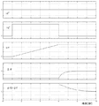
本実施の形態6における動作波形の一例を図13に示す。図において、1段目は電流指令のd軸成分id*、2段目は電流指令のq軸成分iq*、3段目は交流回転機1eの回転角周波数ωr、4段目は回転子抵抗誤差(Rr0−Rr)、5段目は電機子インダクタンス誤差(Ls0−Ls)を示している。
時刻0〜1秒の期間は、停止した状態でid*はI1*、iq*は零である。時刻1秒以降、id*とiq*の大きさはI1*を保ち、交流回転機1eの回転角周波数ωrは発生したトルクによって加速して行く。
定数測定手段8eは、時刻3秒に到達するまでは動作を停止しており、時刻3秒に到達すると、第2の電圧指令vd2*およびvq2*に基づいて電機子インダクタンス設定値Ls0を演算することで、Ls0は電機子インダクタンスLsに近づきインダクタンス誤差(Ls0−Ls)は零に収束する。
回転子抵抗についても、定数測定手段8eは、時刻3秒に到達すると、第2の電圧指令vd2*およびvq2*に基づいて回転子抵抗設定値Rr0を演算することで、Rr0は回転子抵抗Rrに近づき回転子抵抗誤差(Rr0−Rr)は零に収束する。
An example of the operation waveform in the sixth embodiment is shown in FIG. In the figure, the first stage is the d-axis component id * of the current command, the second stage is the q-axis component iq * of the current command, the third stage is the rotational angular frequency ωr of the AC rotating machine 1e, and the fourth stage is the rotor resistance. The error (Rr0-Rr) and the fifth stage show the armature inductance error (Ls0-Ls).
During the period from
The constant measuring means 8e stops operating until reaching
Also for the rotor resistance, when the constant measurement means 8e reaches 3 seconds, the constant resistance measuring means 8e calculates the rotor resistance setting value Rr0 based on the second voltage commands vd2 * and vq2 * , so that Rr0 is the rotor resistance Rr. The rotor resistance error (Rr0-Rr) converges to zero.
また、(84)、(85)式は回転子抵抗や電機子インダクタンスの設定値を第2の電圧指令を積分して得るようにしたので、電圧検出値や電流検出値のノイズが直接反映することを防ぎ、測定した定数もノイズの影響を受ける問題を解決することができる。
なお、本実施の形態6に示した定数測定手段8eは、電機子インダクタンス設定値Ls0の演算を行ったが、誘導機である交流回転機1eにはLs≒Lr≒Mの関係があるので、定数測定手段8eはLs0の代わりに回転子インダクタンス若しくは相互インダクタンスの設定値を演算しても良い。
In addition, since the equations (84) and (85) are obtained by integrating the second voltage command with the set values of the rotor resistance and the armature inductance, the noise of the voltage detection value and the current detection value is directly reflected. The problem that the measured constants are also affected by noise can be solved.
Although the constant measuring means 8e shown in the sixth embodiment calculates the armature inductance set value Ls0, the AC rotating machine 1e that is an induction machine has a relationship of Ls≈Lr≈M. The constant measuring means 8e may calculate a set value of the rotor inductance or mutual inductance instead of Ls0.
以上のように、本実施の形態6では、交流回転機1eは誘導機であって、第2の電圧指令演算手段9は、定数測定手段8eが出力する電気的定数を用いて交流回転機1eのすべり角周波数ωsを演算するとともに、このすべり角周波数ωsと交流回転機1eの回転角周波数ωrとの和を任意の角周波数ωとして出力する加算器51を備えたので、交流回転機1eがすべりが発生する誘導機であっても、該交流回転機1eの電気的定数を得ることができるという効果がある。
また、交流回転機1eは誘導機であって、定数測定手段8eは、相互インダクタンス値、電機子インダクタンス値、回転子抵抗値を第2の電圧指令に基づいて演算し第1の電圧指令演算手段7eに出力するので、誘導機の、電機子インダクタンス値と回転子抵抗値を定数測定手段8eが測定し、第1の電圧指令演算手段7eで用いる電気的定数として設定することができる。
As described above, in the sixth embodiment, the AC rotating machine 1e is an induction machine, and the second voltage command calculating means 9 uses the electrical constant output from the constant measuring means 8e to use the AC rotating machine 1e. Since the
The AC rotating machine 1e is an induction machine, and the
また、定数測定手段8eは、第2の電圧指令演算手段9が出力する第2の電圧指令のd軸成分とq軸成分との和に基づいて、電機子インダクタンス値を演算し、その演算結果を第1の電圧指令演算手段7eに出力するので、誘導機である交流回転機1eの電機子インダクタンス値をより正確に測定し、第1の電圧指令演算手段7eで用いる電気的定数の設定を行えるという効果がある。
また、定数測定手段8eは、第2の電圧指令演算手段9が出力する第2の電圧指令のd軸成分とq軸成分との差に基づいて回転子抵抗値を演算し、その演算結果を第1の電圧指令演算手段7eに出力するので、誘導機である交流回転機1eの回転子抵抗を正確に測定し、第1の電圧指令演算手段7eで用いる電気的定数の設定を行えるという効果がある。
The constant measuring means 8e calculates the armature inductance value based on the sum of the d-axis component and the q-axis component of the second voltage command output from the second voltage command calculating means 9, and the calculation result Is output to the first voltage command calculation means 7e, so that the armature inductance value of the AC rotating machine 1e, which is an induction machine, is measured more accurately, and the electrical constant used by the first voltage command calculation means 7e is set. There is an effect that can be done.
The constant measuring means 8e calculates the rotor resistance value based on the difference between the d-axis component and the q-axis component of the second voltage command output from the second voltage command calculating means 9, and the calculation result is calculated. Since it is output to the first voltage command calculation means 7e, the rotor resistance of the AC rotating machine 1e, which is an induction machine, can be accurately measured, and the electrical constant used by the first voltage command calculation means 7e can be set. There is.
以上のように、本実施の形態6では、定数測定手段8eが、回転二軸座標(d−q軸)上の電流指令のd軸成分とq軸成分とを所定値I1*に保ち、第2の電圧指令演算手段9が出力する第2の電圧指令に基づいて交流回転機1eの電気的定数を演算するので、誘導機の電機子インダクタンスおよび回転子抵抗といった2種類の電気的定数の測定ができるという効果がある。即ち、定数測定手段8eは、回転二軸座標(d−q軸)上の電流指令のd軸成分の大きさとq軸成分の大きさが等しいときの第2の電圧指令演算手段9が出力する第2の電圧指令に基づいて交流回転機1eの電気的定数を演算するので、電機子インダクタンスと回転子抵抗といった交流回転機の電気的定数を測定し、第1の電圧指令演算手段7eで用いる電気的定数の設定を行えるという効果がある。
As described above, in the sixth embodiment, the
実施の形態7.
先の実施の形態6では、定数測定手段8eは(84)、(85)式に従い、第2の電圧指令vd2*およびvq2*に基づいて交流回転機1eの電機子インダクタンス設定値Ls0と回転子抵抗設定値Rr0とを演算していたが、第2の電圧指令vd2*、vq2*、電流指令id*、iq*および角周波数ωに基づいて電機子インダクタンス設定値Ls0と回転子抵抗設定値Rr0とを演算しても良い。
In the previous sixth embodiment, the constant measuring means 8e follows the equations (84) and (85) and the armature inductance set value Ls0 of the AC rotating machine 1e and the rotor based on the second voltage commands vd2 * and vq2 *. Although the resistance set value Rr0 is calculated, the armature inductance set value Ls0 and the rotor resistance set value Rr0 are calculated based on the second voltage commands vd2 * , vq2 * , the current commands id * , iq *, and the angular frequency ω. And may be calculated.
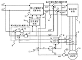
図14は、本発明の実施の形態7による構成を示すブロック図であり、定数測定手段8fは、電機子インダクタンス設定値Ls0と回転子抵抗設定値Rr0とを第2の電圧指令vd2*、vq2*、電流指令id*、iq*および角周波数ωに基づいて演算し、第1の電圧指令演算手段7eにLs0およびRr0を出力する。なお、図14において、図1と同一の符号を付したものは、同一またはこれに相当するものであり、重複する部分の個々の説明は省略する。 FIG. 14 is a block diagram showing a configuration according to the seventh embodiment of the present invention. The constant measuring means 8f uses the armature inductance setting value Ls0 and the rotor resistance setting value Rr0 as the second voltage commands vd2 * and vq2. * Based on the current command id * , iq * and the angular frequency ω, Ls0 and Rr0 are output to the first voltage command calculation means 7e. In FIG. 14, the same reference numerals as those in FIG. 1 denote the same or corresponding parts, and the description of the overlapping parts is omitted.
(80)、(81)式を(86)、(87)式として再掲する。 Expressions (80) and (81) are re-displayed as expressions (86) and (87).
Ls0−Ls≒−(vd2*×iq*+vq2*×id*)÷(ω×id*2)
・・・(86)
Rr0−Rr≒(vd2*×id*−vq2*×iq*)×Rr0
÷(ω×Ls0×id*×iq*) ・・・(87)
Ls0−Ls≈− (vd2 * × iq * + vq2 * × id * ) ÷ (ω × id * 2 )
... (86)
Rr0−Rr≈ (vd2 * × id * −vq2 * × iq * ) × Rr0
÷ (ω × Ls0 × id * × iq * ) (87)
この(86)式右辺は、−(vd2*×iq*+vq2*×id*)の大きさに比例し、id*2の大きさに反比例するとともに、ωの大きさに反比例する。
また、(87)式右辺は、(vd2*×iq*−vq2*×id*)の大きさに比例し、(id*×iq*)の大きさに反比例するとともに、ωの大きさに反比例する。
これらを勘案し、本実施の形態7に示す定数測定手段8fは、(88)、(89)式に基づいて交流回転機1eの電機子インダクタンス設定値Ls0と回転子抵抗設定値Rr0とを第1の電圧指令演算手段7eに出力する。
The right side of the equation (86) is proportional to the magnitude of-(vd2 ** iq * + vq2 ** id * ), inversely proportional to the magnitude of id * 2 , and inversely proportional to the magnitude of ω.
The right side of the equation (87) is proportional to the size of (vd2 * × iq * −vq2 * × id * ), inversely proportional to the size of (id * × iq * ), and inversely proportional to the size of ω. To do.
Taking these into consideration, the constant measuring means 8f shown in the seventh embodiment calculates the armature inductance setting value Ls0 and the rotor resistance setting value Rr0 of the AC rotating machine 1e based on the equations (88) and (89). 1 to the voltage command calculation means 7e.
Ls0= kLs∫{(vd2*×iq*+vq2*×id*)
÷(ω×id*2)}dt ・・・(88)
Rr0=−kRr∫{(vd2*×id*−vq2*×iq*)
÷(ω×id*×iq*)}dt ・・・(89)
但し、kLs、kRr:比例定数
Ls0 = k Ls ∫ {(vd2 * × iq * + vq2 * × id *)
÷ (ω × id * 2 )} dt (88)
Rr0 = −k Rr ∫ {(vd2 * × id * −vq2 * × iq * )
÷ (ω × id * × iq * )} dt (89)
Where k Ls and k Rr are proportional constants
先の実施の形態6では、id*とiq*は正の一定値で、かつ角周波数ωも正であるという制約が伴った。本実施の形態7では、定数測定手段8fが(88)、(89)式を用いるので、iq*の符号や大きさ、およびωの符号や大きさに拘わらず、正確な電機子インダクタンス設定値Ls0と回転子抵抗設定値Rr0との演算を行うことができる。 In the previous sixth embodiment, there is a restriction that id * and iq * are positive constant values and the angular frequency ω is also positive. In the seventh embodiment, since the constant measuring means 8f uses the equations (88) and (89), an accurate armature inductance setting value is obtained regardless of the sign and size of iq * and the sign and size of ω. Calculation of Ls0 and rotor resistance set value Rr0 can be performed.
図15は、本実施の形態7における定数測定手段8fの内部構成を示す図である。図において、乗算器60は、第2の電圧指令のd軸成分vd2*と電流指令のq軸成分iq*との積を演算し、乗算器61は、第2の電圧指令のq軸成分vq2*と電流指令のd軸成分id*との積を演算する。加算器62は、乗算器60の出力と乗算器61の出力とを加算する。乗算器63は、電流指令のd軸成分id*の二乗と角周波数ωとの積を演算しリミッタ64に出力する。リミッタ64は、乗算器63の出力が正の場合は正の所定値以上になるようにリミット動作を行うとともに、乗算器63の出力が負の場合は負の所定値以下になるようにリミット動作を行うことによって、除算器65が零で除算しないようにする。除算器65は、加算器62の出力をリミッタ64の出力で除算し、積分器66は、除算器65の値を積分してkLs倍し、電機子インダクタンス設定値Ls0として出力する。乗算器60、乗算器61、加算器62、乗算器63、リミッタ64、除算器65、積分器66による一連の演算によって(88)式の演算を行うことができる。
FIG. 15 is a diagram showing an internal configuration of the constant measuring means 8f in the seventh embodiment. In the figure, the
同様に、乗算器67は、第2の電圧指令のd軸成分vd2*と電流指令のd軸成分id*との積を演算し、乗算器68は、第2の電圧指令のq軸成分vq2*と電流指令のq軸成分iq*との積を演算する。減算器69は、乗算器67の出力から乗算器68の出力を減算する。乗算器70は、電流指令id*とiq*と角周波数ωとの積を演算しリミッタ71に出力する。リミッタ71は、乗算器70の出力が正の場合は正の所定値以上になるようにリミット動作を行うとともに、乗算器70の出力が負の場合は負の所定値以下になるようにリミット動作を行うことによって、除算器72が零で除算しないようにする。除算器72は、減算器69の出力をリミッタ71の出力で除算し、積分器73は、除算器72の値を積分して−kRr倍し、回転子抵抗設定値Rr0として出力する。乗算器67、乗算器68、減算器69、乗算器70、リミッタ71、除算器72、積分器73による一連の演算によって(89)式の演算を行うことができる。
Similarly, the multiplier 67, the product of the d-axis component id * of the d-
以上のように、本実施の形態7では、定数測定手段8fは、第2の電圧指令vd2*、vq2*、電流指令のid*、iq*および角周波数ωに基づいて回転子抵抗設定値Rr0と電機子インダクタンス設定値Ls0とを演算するようにしたので、電流指令id*、iq*および角周波数ωの符号や大きさに拘わらず、正確な回転子抵抗設定値および電機子インダクタンス設定値を得る効果がある。
As described above, in the seventh embodiment, the
実施の形態8.
先の実施の形態7では、電流指令のd軸成分id*を所定値で与えていたが、角周波数ωが基準角周波数ωBASE(電圧飽和が発生しない最大角周波数)であるときに電圧印加手段2が出力可能な最大電圧振幅になるようにid*を調整しても良い。
交流回転機1eの電圧振幅を大きくすることができれば、同じ出力に対して電流振幅を小さくすることができ、銅損などの損失低減による高効率制御が可能になる。しかし、電圧印加手段2が出力できないような電圧振幅に制御しようとすると電圧飽和が発生し、所望の制御特性が得られない。そこで、電圧印加手段2の出力する角周波数が基準角周波数ωBASEであるときに出力可能な最大電圧振幅になるようにid*の調整をすることで、角周波数ωが基準角周波数ωBASE以下では電圧飽和が発生しない範囲で電圧振幅が大きくなるようにする。
In the
If the voltage amplitude of the AC rotating machine 1e can be increased, the current amplitude can be reduced with respect to the same output, and high-efficiency control by reducing losses such as copper loss becomes possible. However, if it is attempted to control the voltage amplitude such that the
以上の観点から、この実施の形態8は、電気的定数の概念を広く捉え、電流指令のd軸成分id*を電気的定数として扱い、このid*を求める磁束調整手段80を新たに設けたものである。
図16は、本発明の実施の形態8による構成を示すブロック図であり、磁束調整手段80は、電圧印加手段2に入力される第3の電圧指令vd3*,vq3*および角周波数ωに基づいて電流指令のd軸成分id*を出力する。公知の通り、交流回転機1eの磁束振幅は、電流指令のd軸成分id*に比例するので、id*を調整することは交流回転機1eの磁束を調整することでもある。なお、図16において図14と同一の符号を付したものは、同一またはこれに相当するものであり、重複部分の個々の説明は省略する。
From the above point of view, this
FIG. 16 is a block diagram showing a configuration according to the eighth embodiment of the present invention. The magnetic flux adjusting means 80 is based on the third voltage commands vd3 * , vq3 * and the angular frequency ω input to the
磁束調整手段80の動作説明をする前に、交流回転機1eの電圧振幅、即ち、電圧印加手段2に入力される第3の電圧指令の振幅と、電流指令のd軸成分id*との関係について説明する。
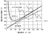
図17は、角周波数50÷2π[rad/s]および60÷2π[rad/s]における電流指令id*と電圧指令の振幅との関係を示す図であり、電圧指令の振幅は(90)式で定義する。
Before explaining the operation of the magnetic flux adjusting means 80, the relationship between the voltage amplitude of the AC rotating machine 1e, that is, the amplitude of the third voltage command input to the
FIG. 17 is a diagram showing the relationship between the current command id * and the amplitude of the voltage command at
電圧指令の振幅=√(vd3*2+vq3*2) ・・・(90) Voltage command amplitude = √ (vd3 * 2 + vq3 * 2 ) (90)
図17を見て判るように、電流指令のd軸成分id*を100%よりも大きくすると電圧指令の振幅は大きくなると同時に、id*を20%よりも小さくしても電圧指令の振幅は大きくなるのでid*と電圧指令の振幅とは比例関係ではない。しかしながら、id*が100%近傍である範囲に限定すると、図17の近似直線のように、id*と電圧指令の振幅とが比例する関係であると見なしても良い。
図18は、角周波数ωと電圧指令の振幅との関係を示す図であり、id*が50〜200%の範囲であれば、角周波数ωと電圧指令の振幅との関係は概ね比例関係であると言っても良い。特に、基準角周波数ωBASEを60×2π[rad/s]に設定する場合、電流指令のd軸成分id*が50〜200%、かつ、角周波数ωが基準角周波数ωBASE近傍では、角周波数ωと電圧指令の振幅とは比例関係にあり、また、id*と電圧指令の振幅とも比例関係にあると言っても良い。換言すると、次の関係が成り立つ。
As can be seen from FIG. 17, when the d-axis component id * of the current command is made larger than 100%, the amplitude of the voltage command becomes large, and at the same time, the amplitude of the voltage command becomes large even if id * is made smaller than 20%. Therefore, id * and the amplitude of the voltage command are not proportional. However, if it is limited to a range where id * is in the vicinity of 100%, it may be considered that id * is proportional to the amplitude of the voltage command, as shown by the approximate line in FIG.
FIG. 18 is a diagram illustrating the relationship between the angular frequency ω and the amplitude of the voltage command. When id * is in the range of 50 to 200%, the relationship between the angular frequency ω and the amplitude of the voltage command is approximately proportional. It can be said that there is. In particular, when the reference angular frequency ω BASE is set to 60 × 2π [rad / s], when the d-axis component id * of the current command is 50 to 200% and the angular frequency ω is near the reference angular frequency ω BASE , the angle It can be said that the frequency ω and the amplitude of the voltage command are in a proportional relationship, and id * and the amplitude of the voltage command are also in a proportional relationship. In other words, the following relationship holds.
電圧指令の振幅 ∝ ω×id*
但し、電流指令のd軸成分id*は、100%近傍、かつ、角周波数ωは、ωBASE近傍とする。
Voltage command amplitude ∝ ω × id *
However, the d-axis component id * of the current command is near 100%, and the angular frequency ω is near ω BASE .
以上の関係を勘案して、磁束調整手段80は、電圧印加手段2に入力される第3の電圧指令vd3*、vq3*および角周波数ωに基づいて、角周波数ωが基準角周波数ωBASEであるときに電圧印加手段2が出力可能な最大電圧振幅になるようにid*を調整する。
Considering the above relationship, the magnetic flux adjusting means 80 determines that the angular frequency ω is the reference angular frequency ω BASE based on the third voltage commands vd3 * , vq3 * and the angular frequency ω input to the
図19は、本実施の形態における磁束調整手段80の内部構成を示す図である。図において、絶対値演算器90は、角周波数ωの絶対値を演算し、ゲイン演算器91は、絶対値演算器90の出力を1/ωBASE倍する。乗算器92は、第3の電圧指令のd軸成分vd3*の二乗を演算し、乗算器93は、第3の電圧指令のq軸成分vq3*の二乗を演算する。
加算器94は、乗算器92の出力と乗算器93の出力との加算演算を行い、平方演算器95は、加算器94の平方を演算し、ゲイン演算器96は、平方演算器95の出力を1/VBASE倍する。ここで、VBASEは電圧印加手段2が出力可能な最大電圧振幅である。
減算器97は、ゲイン演算器91の出力からゲイン演算器96の出力を減算し、増幅器98は、減算器97の出力を積分若しくは比例積分によって増幅する。この比例積分によって「絶対値演算器90の出力の1/ωBASE倍」と「平方演算器95の出力の1/VBASE倍」とを一致させることが可能であり、その結果、角周波数ωがωBASEであるときに電圧指令の振幅がVBASEになるような電流指令のd軸成分id*を出力できる。リミッタ99は、増幅器98の出力がid*の50〜200%になるように上限と下限をリミットする。
定数測定手段として機能する磁束調整手段80を図19の構成にすることにより、角周波数ωがωBASEであるときに電圧指令の振幅がVBASEになるような電流指令のd軸成分id*を出力することができる。
FIG. 19 is a diagram showing an internal configuration of the magnetic flux adjusting means 80 in the present embodiment. In the figure, an
The
The
The magnetic flux adjusting means 80 functioning as the constant measuring means is configured as shown in FIG. 19, so that the d-axis component id * of the current command such that the amplitude of the voltage command becomes V BASE when the angular frequency ω is ω BASE is obtained. Can be output.
本実施の形態8における動作波形の一例を図20に示す。図において、1段目は電流指令のd軸成分id*、2段目は電流指令のq軸成分iq*、3段目は交流回転機1eの回転角周波数ωr、4段目は回転子抵抗誤差(Rr0−Rr)、5段目は電機子インダクタンス誤差(Ls0−Ls)を示している。
時刻0〜1秒の期間は、停止した状態でid*はI1*、iq*は零である。時刻1秒以降、id*とiq*の大きさはI1*を保ち、交流回転機1eの回転角周波数ωrは発生したトルクによって加速して行く。定数測定手段8fは、時刻3秒に到達するまでは動作を停止しており、時刻3秒に到達すると、第2の電圧指令vd2*およびvq2*に基づいて電機子インダクタンス設定値Ls0を演算することで、Ls0は電機子インダクタンスLsに近づき電機子インダクタンス誤差(Ls0−Ls)は零に収束する。
An example of the operation waveform in the eighth embodiment is shown in FIG. In the figure, the first stage is the d-axis component id * of the current command, the second stage is the q-axis component iq * of the current command, the third stage is the rotational angular frequency ωr of the AC rotating machine 1e, and the fourth stage is the rotor resistance. The error (Rr0-Rr) and the fifth stage show the armature inductance error (Ls0-Ls).
During the period from
回転子抵抗についても、定数測定手段8fは、時刻3秒に到達すると、第2の電圧指令vd2*およびvq2*に基づいて回転子抵抗設定値Rr0を演算することで、Rr0は回転子抵抗Rrに近づき回転子抵抗誤差(Rr0−Rr)は零に収束する。
磁束調整手段80は、時刻8秒に到達するまでは動作を停止している。I1*に保たれている電流指令のd軸成分id*は100%近傍であり、かつ、時刻8秒に到達した時点で角周波数ωはωBASE近傍となるので、時刻8秒から磁束調整手段80は動作を開始し、角周波数ωがωBASEであるときに電圧印加手段2が出力可能な最大電圧振幅VBASEになるようなid*の調整ができる。
Also for the rotor resistance, when the constant measurement means 8f reaches 3 seconds, the constant resistance measuring means 8f calculates the rotor resistance setting value Rr0 based on the second voltage commands vd2 * and vq2 * , so that Rr0 is the rotor resistance Rr. The rotor resistance error (Rr0-Rr) converges to zero.
The magnetic
以上のように、本実施の形態8では、磁束調整手段80が所定速度近傍で電圧指令の振幅の定数倍が角周波数ωの定数倍に一致するように電流指令のd軸成分id*を調整することで、交流回転機1eの磁束を調整するようにしたので、電圧印加手段2が基準角周波数ωBASEであるときに出力可能な最大電圧振幅になるようなid*を得、角周波数ωが基準角周波数ωBASE以下では電圧飽和が発生しない範囲で電圧振幅が大きくなるようにできるので、交流回転機1eを安定かつ効率良く制御することができるという効果がある。
As described above, in the eighth embodiment, the magnetic
また、この発明の各変形例において、定数測定手段は、定数設定値を、第2の電圧指令演算手段からの第2の電圧指令、電流指令および角周波数に基づき演算するので、定数設定値を演算する条件が緩和され、定数設定値を求める演算の収束性が向上する。 In each modification of the present invention, the constant measuring means calculates the constant set value based on the second voltage command, current command and angular frequency from the second voltage command calculating means. The calculation condition is relaxed, and the convergence of the calculation for obtaining the constant set value is improved.
また、交流回転機は同期機であって、定数測定手段は、第2の電圧指令のq軸成分に基づき、定数設定値としての電機子抵抗設定値を演算するので、交流回転機である同期機の電機子抵抗が、簡便に精度よく求められる。 The AC rotating machine is a synchronous machine, and the constant measuring means calculates an armature resistance set value as a constant set value based on the q-axis component of the second voltage command. The armature resistance of the machine is required simply and accurately.
交流回転機は同期機であって、定数測定手段は、第2の電圧指令のd軸成分に基づき、定数設定値としての電機子インダクタンス設定値を演算するので、交流回転機である同期機の電機子インダクタンスが、簡便に精度よく求められる。 The AC rotating machine is a synchronous machine, and the constant measuring means calculates an armature inductance setting value as a constant setting value based on the d-axis component of the second voltage command. Armature inductance is required simply and accurately.
また、交流回転機は同期機であって、定数測定手段は、第2の電圧指令のq軸成分と電流指令のq軸成分とに基づき、定数設定値としての電機子抵抗設定値を演算するので、交流回転機である同期機の電機子抵抗が、簡便に精度よく求められる。 The AC rotating machine is a synchronous machine, and the constant measuring means calculates an armature resistance set value as a constant set value based on the q-axis component of the second voltage command and the q-axis component of the current command. Therefore, the armature resistance of the synchronous machine which is an AC rotating machine is easily and accurately obtained.
また、交流回転機は同期機であって、定数測定手段は、第2の電圧指令のd軸成分と電流指令のq軸成分と角周波数とに基づき、定数設定値としての電機子インダクタンス設定値を演算するので、交流回転機である同期機の電機子インダクタンスが、簡便に精度よく求められる。 The AC rotating machine is a synchronous machine, and the constant measuring means is an armature inductance setting value as a constant setting value based on the d-axis component of the second voltage command, the q-axis component of the current command, and the angular frequency. Therefore, the armature inductance of the synchronous machine that is an AC rotating machine is simply and accurately obtained.
また、交流回転機は突極性を有する同期機であって、定数測定手段は、第2の電圧指令のq軸成分に基づき、定数設定値としての電機子インダクタンスのd軸成分設定値を演算するので、交流回転機である突極性を有する同期機の電機子インダクタンスのd軸成分が、簡便に精度よく求められる。 The AC rotating machine is a synchronous machine having saliency, and the constant measuring means calculates the d-axis component set value of the armature inductance as a constant set value based on the q-axis component of the second voltage command. Therefore, the d-axis component of the armature inductance of the synchronous machine having saliency which is an AC rotating machine is simply and accurately obtained.
また、交流回転機は突極性を有する同期機であって、定数測定手段は、第2の電圧指令のd軸成分に基づき、定数設定値としての電機子インダクタンスのq軸成分設定値を演算するので、交流回転機である突極性を有する同期機の電機子インダクタンスのq軸成分が、簡便に精度よく求められる。 The AC rotary machine is a synchronous machine having saliency, and the constant measuring means calculates a q-axis component set value of the armature inductance as a constant set value based on the d-axis component of the second voltage command. Therefore, the q-axis component of the armature inductance of the synchronous machine having saliency which is an AC rotating machine is simply and accurately obtained.
また、交流回転機は突極性を有する同期機であって、定数測定手段は、第2の電圧指令のq軸成分と電流指令のd軸成分と角周波数とに基づき、定数設定値としての電機子インダクタンスのd軸成分設定値を演算するので、交流回転機である突極性を有する同期機の電機子インダクタンスのd軸成分が、簡便迅速に精度よく求められる。 The AC rotating machine is a synchronous machine having saliency, and the constant measuring means is an electric machine as a constant set value based on the q-axis component of the second voltage command, the d-axis component of the current command, and the angular frequency. Since the set value of the d-axis component of the child inductance is calculated, the d-axis component of the armature inductance of the synchronous machine having the saliency which is an AC rotating machine can be obtained simply and quickly with high accuracy.
また、交流回転機は突極性を有する同期機であって、定数測定手段は、第2の電圧指令のd軸成分と電流指令のq軸成分と角周波数とに基づき、定数設定値としての電機子インダクタンスのq軸成分設定値を演算するので、交流回転機である突極性を有する同期機の電機子インダクタンスのq軸成分が、簡便迅速に精度よく求められる。 The AC rotating machine is a synchronous machine having saliency, and the constant measuring means is an electric machine as a constant set value based on the d-axis component of the second voltage command, the q-axis component of the current command, and the angular frequency. Since the q-axis component set value of the child inductance is calculated, the q-axis component of the armature inductance of the synchronous machine having the saliency which is an AC rotating machine can be obtained simply and quickly with high accuracy.
また、交流回転機は同期機であって、定数測定手段は、第2の電圧指令のd軸成分に基づき、d−q軸のd軸と交流回転機の回転子磁束との位相差を演算し、更に、位相差と交流回転機の回転位置検出値とに基づき、定数設定値としての交流回転機の角周波数設定値を演算するので、交流回転機である同期機の角周波数が、簡便に精度よく求められる。 The AC rotating machine is a synchronous machine, and the constant measuring means calculates the phase difference between the d-axis of the dq axis and the rotor magnetic flux of the AC rotating machine based on the d-axis component of the second voltage command. Furthermore, since the angular frequency setting value of the AC rotating machine as a constant setting value is calculated based on the phase difference and the rotational position detection value of the AC rotating machine, the angular frequency of the synchronous machine that is an AC rotating machine is simplified. Is required with high accuracy.
また、交流回転機は同期機であって、定数測定手段は、第2の電圧指令のq軸成分に基づき、定数設定値としての交流回転機の磁束振幅設定値を演算するので、交流回転機である同期機の磁束振幅が、簡便に精度よく求められる。 The AC rotating machine is a synchronous machine, and the constant measuring means calculates the magnetic flux amplitude setting value of the AC rotating machine as a constant setting value based on the q-axis component of the second voltage command. Thus, the magnetic flux amplitude of the synchronous machine can be easily and accurately obtained.
また、交流回転機は誘導機であって、第1の電圧指令演算手段は、d−q軸上の電流指令と電気的定数とに基づき、交流回転機のすべり角周波数を演算し、すべり角周波数と交流回転機の角周波数検出値とから交流回転機の角周波数を演算する加算器を備えたので、交流回転機である誘導機の角周波数が、簡便に精度よく求められる。 The AC rotating machine is an induction machine, and the first voltage command calculation means calculates the slip angular frequency of the AC rotating machine based on the current command on the dq axis and the electrical constant, and the slip angle Since the adder that calculates the angular frequency of the AC rotating machine from the frequency and the detected angular frequency value of the AC rotating machine is provided, the angular frequency of the induction machine that is the AC rotating machine is easily and accurately obtained.
また、定数測定手段は、第2の電圧指令のd軸成分とq軸成分との和に基づき、定数設定値としての電機子インダクタンス設定値、回転子インダクタンス設定値または相互インダクタンス設定値のいずれかを演算するので、交流回転機である誘導機の電機子インダクタンス、回転子インダクタンスまたは相互インダクタンスが、簡便に精度よく求められる。 Further, the constant measuring means is one of an armature inductance setting value, a rotor inductance setting value, and a mutual inductance setting value as a constant setting value based on the sum of the d-axis component and the q-axis component of the second voltage command. Therefore, the armature inductance, rotor inductance, or mutual inductance of the induction machine that is an AC rotating machine is easily and accurately obtained.
また、定数測定手段は、第2の電圧指令のd軸成分とq軸成分との差に基づき、定数設定値としての回転子抵抗設定値を演算するので、交流回転機である誘導機の回転子抵抗が、簡便に精度よく求められる。 Further, the constant measuring means calculates the rotor resistance setting value as the constant setting value based on the difference between the d-axis component and the q-axis component of the second voltage command, so that the rotation of the induction machine that is an AC rotating machine A child resistance is simply and accurately obtained.
また、定数測定手段は、定数設定値を、第2の電圧指令演算手段からの第2の電圧指令、電流指令および角周波数に基づき演算するので、定数設定値を演算する条件が緩和され、定数設定値を求める演算の収束性が向上する。 Further, since the constant measuring means calculates the constant set value based on the second voltage command, current command and angular frequency from the second voltage command calculating means, the condition for calculating the constant set value is relaxed, The convergence of the calculation for obtaining the set value is improved.
また、定数測定手段は、角周波数が所定値以上の範囲にある場合のみ定数設定値を演算し、角周波数が所定値未満の範囲では定数設定値の演算を停止するようにしたので、定数誤差に起因する制御性能の低下を防ぐことが出来る。 In addition, the constant measurement means calculates the constant set value only when the angular frequency is in the range of the predetermined value or more, and stops the calculation of the constant set value when the angular frequency is less than the predetermined value. It is possible to prevent a decrease in control performance due to the above.
また、電圧飽和が発生しない最大角周波数をωBASE、電圧印加手段が出力可能な最大電圧振幅をVBASEとしたとき、第3の電圧指令と角周波数とに基づき、
(前記交流回転機の角周波数)/前記ωBASE=(第3の電圧指令の振幅)/VBASEが成立するよう、電流指令のd軸成分を演算する磁束調整手段を備えたので、電圧飽和が発生しない範囲で電圧振幅が大きくなるようにできるので、交流回転機を安定かつ効率良く制御することができる。
When the maximum angular frequency at which voltage saturation does not occur is ω BASE and the maximum voltage amplitude that can be output by the voltage applying means is V BASE , based on the third voltage command and the angular frequency,
Since magnetic flux adjusting means for calculating the d-axis component of the current command is provided so that (angular frequency of the AC rotating machine) / ω BASE = (amplitude of the third voltage command) / V BASE is established, voltage saturation Since the voltage amplitude can be increased within a range in which no AC occurs, the AC rotating machine can be controlled stably and efficiently.
1,1b,1c,1e 交流回転機、2 電圧印加手段、3 電流検出手段、
4 回転位置検出器、6 座標変換手段、
7,7b,7c,7e 第1の電圧指令演算手段、
8,8a,8b,8c,8d,8e,8f 定数測定手段、
9 第2の電圧指令演算手段、10 第3の電圧指令演算手段、80 磁束調整手段。
1, 1b, 1c, 1e AC rotating machine, 2 voltage applying means, 3 current detecting means,
4 rotational position detector, 6 coordinate conversion means,
7, 7b, 7c, 7e 1st voltage command calculating means,
8, 8a, 8b, 8c, 8d, 8e, 8f Constant measuring means,
9 Second voltage command calculating means, 10th voltage command calculating means, 80 magnetic flux adjusting means.
Claims (19)
前記交流回転機の制御装置は、
前記交流回転機の電流を検出する電流検出手段、前記電流検出手段からの電流検出値を前記d−q軸上の電流検出値に変換する座標変換手段、前記d−q軸上の電流指令と前記角周波数と前記交流回転機の複数の電気的定数との関係式から前記d−q軸上の第1の電圧指令を演算する第1の電圧指令演算手段、前記d−q軸上の電流指令と前記d−q軸上の電流検出値との差分電流が零に収斂するよう前記差分電流に基づき前記d−q軸上の第2の電圧指令を演算する第2の電圧指令演算手段、前記d−q軸上の第1の電圧指令と前記d−q軸上の第2の電圧指令とを加算して前記d−q軸上の第3の電圧指令を演算する第3の電圧指令演算手段、および前記d−q軸上の第3の電圧指令に基づき前記交流回転機に電圧を印加する電圧印加手段を備え、
更に、前記第1の電圧指令演算手段は、その前記複数の電気的定数の少なくとも1つを外部から入力する定数設定値で設定するようにし、
前記定数設定値を、前記第2の電圧指令演算手段からの第2の電圧指令を、もしくは前記第2の電圧指令演算手段からの第2の電圧指令を前記回転二軸座標上の電流指令で除算する演算式により演算した結果を、更に積分し該積分した値に比例定数を乗算する処理を行った結果を前記定数設定値として出力する定数測定手段を備えた交流回転機の制御装置を使用し、
前記電流指令および前記角周波数を所定の値または範囲に設定して前記制御装置を起動し、前記第2の電圧指令が所定の範囲内となった時点における前記定数測定手段からの前記定数設定値を、測定対象である前記交流回転機の電気的定数として出力する交流回転機の電気的定数測定方法。 The AC rotating machine using a controller for the AC rotating machine that drives the AC rotating machine based on a current command on a rotating biaxial coordinate (hereinafter referred to as dq axis) that rotates at an angular frequency of the AC rotating machine. A method for measuring the electrical constant of
The control device for the AC rotating machine is:
Current detection means for detecting the current of the AC rotating machine, coordinate conversion means for converting a current detection value from the current detection means into a current detection value on the dq axis, a current command on the dq axis, and First voltage command calculation means for calculating a first voltage command on the dq axis from a relational expression between the angular frequency and a plurality of electrical constants of the AC rotating machine, current on the dq axis A second voltage command calculating means for calculating a second voltage command on the dq axis based on the difference current so that a difference current between the command and the detected current value on the dq axis converges to zero; A third voltage command for calculating the third voltage command on the dq axis by adding the first voltage command on the dq axis and the second voltage command on the dq axis. A voltage application means for applying a voltage to the AC rotating machine based on a calculation means and a third voltage command on the dq axes Equipped with a,
Further, the first voltage command calculation means sets at least one of the plurality of electrical constants by a constant setting value input from the outside,
The constant set value is a second voltage command from the second voltage command calculating means , or a second voltage command from the second voltage command calculating means is a current command on the rotating biaxial coordinates. A control device for an AC rotating machine provided with constant measuring means for further integrating the result calculated by the arithmetic expression to be divided and multiplying the integrated value by a proportional constant and outputting the result as the constant set value is used. And
The constant setting value from the constant measuring means when the current command and the angular frequency are set to a predetermined value or range, the control device is started, and the second voltage command is within a predetermined range. Is output as an electrical constant of the AC rotating machine to be measured.
前記定数測定手段は、前記第2の電圧指令のq軸成分に基づき、前記定数設定値としての電機子抵抗設定値を演算することを特徴とする請求項1記載の交流回転機の電気的定数測定方法。 The AC rotating machine is a synchronous machine,
2. The electrical constant of an AC rotating machine according to claim 1, wherein the constant measuring means calculates an armature resistance set value as the constant set value based on a q-axis component of the second voltage command. Measuring method.
前記定数測定手段は、前記第2の電圧指令のd軸成分に基づき、前記定数設定値としての電機子インダクタンス設定値を演算することを特徴とする請求項1記載の交流回転機の電気的定数測定方法。 The AC rotating machine is a synchronous machine,
The electrical constant of an AC rotating machine according to claim 1, wherein the constant measuring means calculates an armature inductance setting value as the constant setting value based on a d-axis component of the second voltage command. Measuring method.
前記定数測定手段は、前記第2の電圧指令のq軸成分と前記電流指令のq軸成分とに基づき、前記定数設定値としての電機子抵抗設定値を演算することを特徴とする請求項2記載の交流回転機の電気的定数測定方法。 The AC rotating machine is a synchronous machine,
3. The constant measurement unit calculates an armature resistance set value as the constant set value based on a q-axis component of the second voltage command and a q-axis component of the current command. The electrical constant measurement method of the alternating current rotating machine described .
前記定数測定手段は、前記第2の電圧指令のd軸成分と前記電流指令のq軸成分と前記角周波数とに基づき、前記定数設定値としての電機子インダクタンス設定値を演算することを特徴とする請求項2記載の交流回転機の電気的定数測定方法。 The AC rotating machine is a synchronous machine,
The constant measuring means calculates an armature inductance set value as the constant set value based on a d-axis component of the second voltage command, a q-axis component of the current command, and the angular frequency. The method for measuring an electrical constant of an AC rotating machine according to claim 2 .
前記定数測定手段は、前記第2の電圧指令のq軸成分に基づき、前記定数設定値としての電機子インダクタンスのd軸成分設定値を演算することを特徴とする請求項1記載の交流回転機の電気的定数測定方法。 The AC rotating machine is a synchronous machine having saliency,
2. The AC rotating machine according to claim 1, wherein the constant measuring unit calculates a d-axis component set value of an armature inductance as the constant set value based on a q-axis component of the second voltage command. Electrical constant measurement method.
前記定数測定手段は、前記第2の電圧指令のd軸成分に基づき、前記定数設定値としての電機子インダクタンスのq軸成分設定値を演算することを特徴とする請求項1記載の交流回転機の電気的定数測定方法。 The AC rotating machine is a synchronous machine having saliency,
2. The AC rotating machine according to claim 1, wherein the constant measuring unit calculates a q-axis component set value of an armature inductance as the constant set value based on a d-axis component of the second voltage command. Electrical constant measurement method.
前記定数測定手段は、前記第2の電圧指令のq軸成分と前記電流指令のd軸成分と前記角周波数とに基づき、前記定数設定値としての電機子インダクタンスのd軸成分設定値を演算することを特徴とする請求項2記載の交流回転機の電気的定数測定方法。 The AC rotating machine is a synchronous machine having saliency,
The constant measurement unit calculates a d-axis component set value of the armature inductance as the constant set value based on the q-axis component of the second voltage command, the d-axis component of the current command, and the angular frequency. The method for measuring an electrical constant of an AC rotating machine according to claim 2 .
前記定数測定手段は、前記第2の電圧指令のd軸成分と前記電流指令のq軸成分と前記角周波数とに基づき、前記定数設定値としての電機子インダクタンスのq軸成分設定値を演算することを特徴とする請求項2記載の交流回転機の電気的定数測定方法。 The AC rotating machine is a synchronous machine having saliency,
The constant measuring unit calculates a q-axis component set value of the armature inductance as the constant set value based on the d-axis component of the second voltage command, the q-axis component of the current command, and the angular frequency. The method for measuring an electrical constant of an AC rotating machine according to claim 2 .
前記定数測定手段は、前記第2の電圧指令のd軸成分に基づき、前記d−q軸のd軸と前記交流回転機の回転子磁束との位相差を演算し、更に、前記位相差と前記交流回転機の回転位置検出値とに基づき、前記定数設定値としての前記交流回転機の角周波数設定値を演算することを特徴とする請求項1記載の交流回転機の電気的定数測定方法。 The AC rotating machine is a synchronous machine,
The constant measuring means calculates a phase difference between the d-axis of the dq axis and the rotor magnetic flux of the AC rotating machine based on the d-axis component of the second voltage command, and further, the phase difference The method for measuring an electrical constant of an AC rotating machine according to claim 1, wherein an angular frequency setting value of the AC rotating machine as the constant setting value is calculated based on a rotational position detection value of the AC rotating machine. .
前記定数測定手段は、前記第2の電圧指令のq軸成分に基づき、前記定数設定値としての前記交流回転機の磁束振幅設定値を演算することを特徴とする請求項1記載の交流回転機の電気的定数測定方法。 The AC rotating machine is a synchronous machine,
The constant measurement means, the second based on the q-axis component of the voltage command, the AC rotary machine according to claim 1, wherein computing the flux amplitude set value of the AC rotary machine as the constant setting value Electrical constant measurement method.
前記第1の電圧指令演算手段は、前記d−q軸上の電流指令と前記電気的定数とに基づき、前記交流回転機のすべり角周波数を演算し、
前記すべり角周波数と前記交流回転機の角周波数検出値とから前記交流回転機の角周波数を演算する加算器を備えたことを特徴とする請求項1記載の交流回転機の電気的定数測定方法。 The AC rotating machine is an induction machine,
The first voltage command calculating means calculates a slip angular frequency of the AC rotating machine based on the current command on the dq axis and the electrical constant,
The method for measuring an electrical constant of an AC rotating machine according to claim 1, further comprising an adder that calculates an angular frequency of the AC rotating machine from the slip angular frequency and an angular frequency detection value of the AC rotating machine. .
前記第3の電圧指令と前記角周波数とに基づき、
(前記交流回転機の角周波数)/前記ωBASE=(第3の電圧指令の振幅)/VBASE
が成立するよう、前記電流指令のd軸成分を演算する磁束調整手段を備えたことを特徴とする請求項1ないし17のいずれかに記載の交流回転機の電気的定数測定方法。 When the maximum angular frequency at which no voltage saturation occurs is ω BASE , and the maximum voltage amplitude that can be output by the voltage applying means is V BASE ,
Based on the third voltage command and the angular frequency,
(Angular frequency of the AC rotating machine) / Wω BASE = (Amplitude of the third voltage command) / V BASE
18. The method for measuring an electrical constant of an AC rotating machine according to claim 1, further comprising magnetic flux adjusting means for calculating a d-axis component of the current command so that
Priority Applications (4)
| Application Number | Priority Date | Filing Date | Title |
|---|---|---|---|
| JP2007017800A JP4519864B2 (en) | 2007-01-29 | 2007-01-29 | AC rotating machine electrical constant measuring method and AC rotating machine control apparatus used for carrying out this measuring method |
| US11/851,797 US7800337B2 (en) | 2007-01-29 | 2007-09-07 | Control apparatus for AC rotary machine and method for measuring electrical constant of AC rotary machine using the control apparatus |
| KR1020070096346A KR101046802B1 (en) | 2007-01-29 | 2007-09-21 | Control device of AC rotor and electric constant measurement method of AC rotor using this controller |
| CN2007101618482A CN101237213B (en) | 2007-01-29 | 2007-09-24 | Control apparatus for AC rotary machine and method for measuring electrical constant of ac rotary machine using the control apparatus |
Applications Claiming Priority (1)
| Application Number | Priority Date | Filing Date | Title |
|---|---|---|---|
| JP2007017800A JP4519864B2 (en) | 2007-01-29 | 2007-01-29 | AC rotating machine electrical constant measuring method and AC rotating machine control apparatus used for carrying out this measuring method |
Publications (2)
| Publication Number | Publication Date |
|---|---|
| JP2008187797A JP2008187797A (en) | 2008-08-14 |
| JP4519864B2 true JP4519864B2 (en) | 2010-08-04 |
Family
ID=39667202
Family Applications (1)
| Application Number | Title | Priority Date | Filing Date |
|---|---|---|---|
| JP2007017800A Expired - Fee Related JP4519864B2 (en) | 2007-01-29 | 2007-01-29 | AC rotating machine electrical constant measuring method and AC rotating machine control apparatus used for carrying out this measuring method |
Country Status (4)
| Country | Link |
|---|---|
| US (1) | US7800337B2 (en) |
| JP (1) | JP4519864B2 (en) |
| KR (1) | KR101046802B1 (en) |
| CN (1) | CN101237213B (en) |
Families Citing this family (17)
| Publication number | Priority date | Publication date | Assignee | Title |
|---|---|---|---|---|
| CN101443995B (en) * | 2006-06-29 | 2011-04-27 | 三菱电机株式会社 | Control device for AC rotary machinery |
| JP4301336B2 (en) * | 2007-10-24 | 2009-07-22 | ダイキン工業株式会社 | Power converter |
| DE102008025408A1 (en) * | 2008-05-27 | 2009-12-03 | Sew-Eurodrive Gmbh & Co. Kg | Control or regulating method for a converter |
| JP5178768B2 (en) * | 2010-04-06 | 2013-04-10 | 三菱電機株式会社 | AC rotating machine control device and electric power steering control device |
| JP5656775B2 (en) * | 2011-08-31 | 2015-01-21 | 日立オートモティブシステムズ株式会社 | Power converter |
| KR101221748B1 (en) | 2011-10-27 | 2013-01-11 | 엘에스산전 주식회사 | Apparatus for estimating rotor time constant of induction motor |
| IN2014CN03287A (en) * | 2011-11-17 | 2015-07-03 | Mitsubishi Electric Corp | |
| WO2013080292A1 (en) * | 2011-11-29 | 2013-06-06 | 三菱電機株式会社 | Control device of rotating mechanism and inductance measurement method of rotating mechanism |
| CN103852640B (en) * | 2012-12-04 | 2016-05-04 | 中国北车股份有限公司 | Electric network voltage phase computational methods, device and single phase pulsation width modulation rectification device |
| US9954472B2 (en) * | 2013-11-08 | 2018-04-24 | Mitsubishi Electric Corporation | Control apparatus for AC rotary machine |
| US9923505B2 (en) * | 2013-11-26 | 2018-03-20 | Regal Beloit America, Inc. | Methods and systems for controlling an electric motor |
| US10044310B2 (en) | 2015-03-16 | 2018-08-07 | Deere & Company | Methods of auto tuning machine parameters and systems thereof |
| CN105024613A (en) * | 2015-06-26 | 2015-11-04 | 广东美的制冷设备有限公司 | Obtaining method of motor off-line resistance value, controller and air conditioner |
| KR102036031B1 (en) * | 2017-03-06 | 2019-10-25 | 엘에스산전 주식회사 | Apparatus for controlling inverter |
| US11218100B2 (en) * | 2018-01-12 | 2022-01-04 | Mitsubishi Electric Corporation | Rotary machine control device |
| JP7029368B2 (en) * | 2018-09-06 | 2022-03-03 | 株式会社日立産機システム | Synchronous motor control device |
| KR102226076B1 (en) * | 2019-03-26 | 2021-03-09 | 엘에스일렉트릭(주) | Motor driving system |
Citations (2)
| Publication number | Priority date | Publication date | Assignee | Title |
|---|---|---|---|---|
| JP2001251889A (en) * | 2000-03-06 | 2001-09-14 | Hitachi Ltd | Conjecturing method for position of rotor in synchronous motor, and method and apparatus for sensorless control of position |
| JP2004297966A (en) * | 2003-03-28 | 2004-10-21 | Hitachi Ltd | Ac motor controlling device |
Family Cites Families (14)
| Publication number | Priority date | Publication date | Assignee | Title |
|---|---|---|---|---|
| JPH0319653A (en) | 1989-06-15 | 1991-01-28 | Matsushita Electric Ind Co Ltd | Apparatus for producing ice cream |
| JPH05103471A (en) * | 1991-10-03 | 1993-04-23 | Toshiba Corp | Control method for inverter |
| JP3019653B2 (en) | 1993-03-12 | 2000-03-13 | 株式会社日立製作所 | Control device for AC motor and method for measuring constants of AC motor |
| DE69306703T2 (en) * | 1992-09-16 | 1997-04-30 | Hitachi Ltd | Method for measuring characteristic constants for AC motors and controller based on this method |
| JP3196390B2 (en) * | 1992-12-25 | 2001-08-06 | 富士電機株式会社 | Parameter identifier |
| JP3166525B2 (en) * | 1994-12-28 | 2001-05-14 | 三菱電機株式会社 | Induction motor vector control device |
| JP3468459B2 (en) | 1999-09-01 | 2003-11-17 | 東洋電機製造株式会社 | Control device for permanent magnet type synchronous motor |
| JP3520002B2 (en) * | 1999-12-08 | 2004-04-19 | 三菱電機株式会社 | Vector control device for induction motor |
| JP2002171797A (en) | 2000-11-29 | 2002-06-14 | Toyo Electric Mfg Co Ltd | Control device for permanent magnet synchronous motor |
| KR100428505B1 (en) * | 2001-07-06 | 2004-04-28 | 삼성전자주식회사 | Method of speed speed and flux estimation for induction motor |
| WO2004109310A1 (en) | 2003-06-06 | 2004-12-16 | Mitsubishi Denki Kabushiki Kaisha | Device for determining constant of rotating machine |
| GB2413905B (en) * | 2004-05-05 | 2006-05-03 | Imra Europ S A S Uk Res Ct | Permanent magnet synchronous motor and controller therefor |
| CN100533947C (en) | 2004-07-21 | 2009-08-26 | 三菱电机株式会社 | Ac rotary machine constant measuring apparatus |
| JP4475528B2 (en) * | 2005-03-17 | 2010-06-09 | 日立アプライアンス株式会社 | Synchronous motor control device and adjustment method thereof |
-
2007
- 2007-01-29 JP JP2007017800A patent/JP4519864B2/en not_active Expired - Fee Related
- 2007-09-07 US US11/851,797 patent/US7800337B2/en not_active Expired - Fee Related
- 2007-09-21 KR KR1020070096346A patent/KR101046802B1/en active IP Right Grant
- 2007-09-24 CN CN2007101618482A patent/CN101237213B/en not_active Expired - Fee Related
Patent Citations (2)
| Publication number | Priority date | Publication date | Assignee | Title |
|---|---|---|---|---|
| JP2001251889A (en) * | 2000-03-06 | 2001-09-14 | Hitachi Ltd | Conjecturing method for position of rotor in synchronous motor, and method and apparatus for sensorless control of position |
| JP2004297966A (en) * | 2003-03-28 | 2004-10-21 | Hitachi Ltd | Ac motor controlling device |
Also Published As
| Publication number | Publication date |
|---|---|
| KR20080071055A (en) | 2008-08-01 |
| US20080180054A1 (en) | 2008-07-31 |
| CN101237213A (en) | 2008-08-06 |
| KR101046802B1 (en) | 2011-07-05 |
| CN101237213B (en) | 2010-11-03 |
| JP2008187797A (en) | 2008-08-14 |
| US7800337B2 (en) | 2010-09-21 |
Similar Documents
| Publication | Publication Date | Title |
|---|---|---|
| JP4519864B2 (en) | AC rotating machine electrical constant measuring method and AC rotating machine control apparatus used for carrying out this measuring method | |
| JP5324159B2 (en) | Motor control device | |
| JP5130031B2 (en) | Position sensorless control device for permanent magnet motor | |
| KR102108911B1 (en) | Drive system and inverter device | |
| WO2016121237A1 (en) | Inverter control device and motor drive system | |
| US10637381B2 (en) | Inverter control device and drive system | |
| JP5709932B2 (en) | Synchronous machine controller | |
| JP3707528B2 (en) | AC motor control method and control apparatus therefor | |
| JP2010035363A (en) | Controller for permanent magnet type synchronous motor | |
| JP2004032907A (en) | Controller for permanent magnet type synchronous motor | |
| JP5648310B2 (en) | Synchronous motor control device and synchronous motor control method | |
| JP3914107B2 (en) | DC brushless motor control device | |
| JP2010035352A (en) | Device for estimating rotor position of synchronous electric motor | |
| JP2008206330A (en) | Device and method for estimating magnetic pole position of synchronous electric motor | |
| JP2010166638A (en) | Controller of rotating electrical machine | |
| JP2004266885A (en) | Motor controller and method of detecting deviation from controlled state | |
| JP7304891B2 (en) | Rotating machine control device and electric vehicle control device | |
| JP2006230200A (en) | Control unit of ac motor | |
| JP2006158046A (en) | Sensorless control method and apparatus of ac electric motor | |
| JP2011239518A (en) | Method and apparatus for estimating position and speed of rotor of stepping motor | |
| JP6591794B2 (en) | Induction machine power converter, second-order time constant measuring method and speed control method | |
| JP7251424B2 (en) | INVERTER DEVICE AND INVERTER DEVICE CONTROL METHOD | |
| JP2009165333A (en) | Controller of synchronous electric motor | |
| JP5854057B2 (en) | Step-out detection device and motor drive system | |
| JP7226211B2 (en) | INVERTER DEVICE AND INVERTER DEVICE CONTROL METHOD |
Legal Events
| Date | Code | Title | Description |
|---|---|---|---|
| A621 | Written request for application examination |
Free format text: JAPANESE INTERMEDIATE CODE: A621 Effective date: 20090106 |
|
| A131 | Notification of reasons for refusal |
Free format text: JAPANESE INTERMEDIATE CODE: A131 Effective date: 20090217 |
|
| A521 | Written amendment |
Free format text: JAPANESE INTERMEDIATE CODE: A523 Effective date: 20090415 |
|
| A131 | Notification of reasons for refusal |
Free format text: JAPANESE INTERMEDIATE CODE: A131 Effective date: 20091110 |
|
| A521 | Written amendment |
Free format text: JAPANESE INTERMEDIATE CODE: A523 Effective date: 20091224 |
|
| TRDD | Decision of grant or rejection written | ||
| A01 | Written decision to grant a patent or to grant a registration (utility model) |
Free format text: JAPANESE INTERMEDIATE CODE: A01 Effective date: 20100518 |
|
| A01 | Written decision to grant a patent or to grant a registration (utility model) |
Free format text: JAPANESE INTERMEDIATE CODE: A01 |
|
| A61 | First payment of annual fees (during grant procedure) |
Free format text: JAPANESE INTERMEDIATE CODE: A61 Effective date: 20100519 |
|
| FPAY | Renewal fee payment (event date is renewal date of database) |
Free format text: PAYMENT UNTIL: 20130528 Year of fee payment: 3 |
|
| R150 | Certificate of patent or registration of utility model |
Ref document number: 4519864 Country of ref document: JP Free format text: JAPANESE INTERMEDIATE CODE: R150 Free format text: JAPANESE INTERMEDIATE CODE: R150 |
|
| FPAY | Renewal fee payment (event date is renewal date of database) |
Free format text: PAYMENT UNTIL: 20140528 Year of fee payment: 4 |
|
| R250 | Receipt of annual fees |
Free format text: JAPANESE INTERMEDIATE CODE: R250 |
|
| R250 | Receipt of annual fees |
Free format text: JAPANESE INTERMEDIATE CODE: R250 |
|
| R250 | Receipt of annual fees |
Free format text: JAPANESE INTERMEDIATE CODE: R250 |
|
| R250 | Receipt of annual fees |
Free format text: JAPANESE INTERMEDIATE CODE: R250 |
|
| LAPS | Cancellation because of no payment of annual fees |