EP1132700A1 - Procédé et installation de séparation d'air par distillation cryogénique - Google Patents
Procédé et installation de séparation d'air par distillation cryogénique Download PDFInfo
- Publication number
- EP1132700A1 EP1132700A1 EP01400413A EP01400413A EP1132700A1 EP 1132700 A1 EP1132700 A1 EP 1132700A1 EP 01400413 A EP01400413 A EP 01400413A EP 01400413 A EP01400413 A EP 01400413A EP 1132700 A1 EP1132700 A1 EP 1132700A1
- Authority
- EP
- European Patent Office
- Prior art keywords
- column
- air
- fraction
- oxygen
- compressed
- Prior art date
- Legal status (The legal status is an assumption and is not a legal conclusion. Google has not performed a legal analysis and makes no representation as to the accuracy of the status listed.)
- Granted
Links
- 238000004821 distillation Methods 0.000 title claims abstract description 17
- 238000000034 method Methods 0.000 title claims description 27
- 238000000926 separation method Methods 0.000 title claims description 5
- IJGRMHOSHXDMSA-UHFFFAOYSA-N Atomic nitrogen Chemical compound N#N IJGRMHOSHXDMSA-UHFFFAOYSA-N 0.000 claims abstract description 75
- QVGXLLKOCUKJST-UHFFFAOYSA-N atomic oxygen Chemical compound [O] QVGXLLKOCUKJST-UHFFFAOYSA-N 0.000 claims abstract description 48
- 239000001301 oxygen Substances 0.000 claims abstract description 48
- 229910052760 oxygen Inorganic materials 0.000 claims abstract description 48
- 239000007788 liquid Substances 0.000 claims abstract description 35
- 229910052757 nitrogen Inorganic materials 0.000 claims abstract description 34
- 239000007789 gas Substances 0.000 claims abstract description 32
- 239000012530 fluid Substances 0.000 claims abstract description 12
- 230000008016 vaporization Effects 0.000 claims abstract description 12
- 239000000047 product Substances 0.000 claims abstract description 8
- 230000006835 compression Effects 0.000 claims abstract description 6
- 238000007906 compression Methods 0.000 claims abstract description 6
- 239000012467 final product Substances 0.000 claims abstract description 3
- XKRFYHLGVUSROY-UHFFFAOYSA-N Argon Chemical compound [Ar] XKRFYHLGVUSROY-UHFFFAOYSA-N 0.000 claims description 16
- 238000004519 manufacturing process Methods 0.000 claims description 12
- 238000002156 mixing Methods 0.000 claims description 12
- 238000009434 installation Methods 0.000 claims description 11
- 229910052786 argon Inorganic materials 0.000 claims description 8
- 238000001816 cooling Methods 0.000 claims description 4
- 238000009834 vaporization Methods 0.000 claims description 3
- 238000011144 upstream manufacturing Methods 0.000 claims description 2
- -1 and Substances 0.000 claims 1
- 239000000463 material Substances 0.000 abstract 1
- 238000010992 reflux Methods 0.000 description 5
- 239000000203 mixture Substances 0.000 description 4
- 239000000243 solution Substances 0.000 description 4
- MYMOFIZGZYHOMD-UHFFFAOYSA-N Dioxygen Chemical compound O=O MYMOFIZGZYHOMD-UHFFFAOYSA-N 0.000 description 3
- 238000002347 injection Methods 0.000 description 3
- 239000007924 injection Substances 0.000 description 3
- 239000006200 vaporizer Substances 0.000 description 2
- 230000002745 absorbent Effects 0.000 description 1
- 239000002250 absorbent Substances 0.000 description 1
- 238000010276 construction Methods 0.000 description 1
- 238000010586 diagram Methods 0.000 description 1
- 229910001873 dinitrogen Inorganic materials 0.000 description 1
- 229910001882 dioxygen Inorganic materials 0.000 description 1
- 235000021183 entrée Nutrition 0.000 description 1
- 230000002706 hydrostatic effect Effects 0.000 description 1
- 230000010354 integration Effects 0.000 description 1
- 239000012263 liquid product Substances 0.000 description 1
- 239000012528 membrane Substances 0.000 description 1
- 238000000746 purification Methods 0.000 description 1
Images


Classifications
-
- F—MECHANICAL ENGINEERING; LIGHTING; HEATING; WEAPONS; BLASTING
- F25—REFRIGERATION OR COOLING; COMBINED HEATING AND REFRIGERATION SYSTEMS; HEAT PUMP SYSTEMS; MANUFACTURE OR STORAGE OF ICE; LIQUEFACTION SOLIDIFICATION OF GASES
- F25J—LIQUEFACTION, SOLIDIFICATION OR SEPARATION OF GASES OR GASEOUS OR LIQUEFIED GASEOUS MIXTURES BY PRESSURE AND COLD TREATMENT OR BY BRINGING THEM INTO THE SUPERCRITICAL STATE
- F25J3/00—Processes or apparatus for separating the constituents of gaseous or liquefied gaseous mixtures involving the use of liquefaction or solidification
- F25J3/02—Processes or apparatus for separating the constituents of gaseous or liquefied gaseous mixtures involving the use of liquefaction or solidification by rectification, i.e. by continuous interchange of heat and material between a vapour stream and a liquid stream
- F25J3/04—Processes or apparatus for separating the constituents of gaseous or liquefied gaseous mixtures involving the use of liquefaction or solidification by rectification, i.e. by continuous interchange of heat and material between a vapour stream and a liquid stream for air
- F25J3/04006—Providing pressurised feed air or process streams within or from the air fractionation unit
- F25J3/04078—Providing pressurised feed air or process streams within or from the air fractionation unit providing pressurized products by liquid compression and vaporisation with cold recovery, i.e. so-called internal compression
- F25J3/04103—Providing pressurised feed air or process streams within or from the air fractionation unit providing pressurized products by liquid compression and vaporisation with cold recovery, i.e. so-called internal compression using solely hydrostatic liquid head
-
- F—MECHANICAL ENGINEERING; LIGHTING; HEATING; WEAPONS; BLASTING
- F25—REFRIGERATION OR COOLING; COMBINED HEATING AND REFRIGERATION SYSTEMS; HEAT PUMP SYSTEMS; MANUFACTURE OR STORAGE OF ICE; LIQUEFACTION SOLIDIFICATION OF GASES
- F25J—LIQUEFACTION, SOLIDIFICATION OR SEPARATION OF GASES OR GASEOUS OR LIQUEFIED GASEOUS MIXTURES BY PRESSURE AND COLD TREATMENT OR BY BRINGING THEM INTO THE SUPERCRITICAL STATE
- F25J3/00—Processes or apparatus for separating the constituents of gaseous or liquefied gaseous mixtures involving the use of liquefaction or solidification
- F25J3/02—Processes or apparatus for separating the constituents of gaseous or liquefied gaseous mixtures involving the use of liquefaction or solidification by rectification, i.e. by continuous interchange of heat and material between a vapour stream and a liquid stream
- F25J3/04—Processes or apparatus for separating the constituents of gaseous or liquefied gaseous mixtures involving the use of liquefaction or solidification by rectification, i.e. by continuous interchange of heat and material between a vapour stream and a liquid stream for air
- F25J3/04006—Providing pressurised feed air or process streams within or from the air fractionation unit
- F25J3/04048—Providing pressurised feed air or process streams within or from the air fractionation unit by compression of cold gaseous streams, e.g. intermediate or oxygen enriched (waste) streams
-
- F—MECHANICAL ENGINEERING; LIGHTING; HEATING; WEAPONS; BLASTING
- F25—REFRIGERATION OR COOLING; COMBINED HEATING AND REFRIGERATION SYSTEMS; HEAT PUMP SYSTEMS; MANUFACTURE OR STORAGE OF ICE; LIQUEFACTION SOLIDIFICATION OF GASES
- F25J—LIQUEFACTION, SOLIDIFICATION OR SEPARATION OF GASES OR GASEOUS OR LIQUEFIED GASEOUS MIXTURES BY PRESSURE AND COLD TREATMENT OR BY BRINGING THEM INTO THE SUPERCRITICAL STATE
- F25J3/00—Processes or apparatus for separating the constituents of gaseous or liquefied gaseous mixtures involving the use of liquefaction or solidification
- F25J3/02—Processes or apparatus for separating the constituents of gaseous or liquefied gaseous mixtures involving the use of liquefaction or solidification by rectification, i.e. by continuous interchange of heat and material between a vapour stream and a liquid stream
- F25J3/04—Processes or apparatus for separating the constituents of gaseous or liquefied gaseous mixtures involving the use of liquefaction or solidification by rectification, i.e. by continuous interchange of heat and material between a vapour stream and a liquid stream for air
- F25J3/04006—Providing pressurised feed air or process streams within or from the air fractionation unit
- F25J3/04048—Providing pressurised feed air or process streams within or from the air fractionation unit by compression of cold gaseous streams, e.g. intermediate or oxygen enriched (waste) streams
- F25J3/0406—Providing pressurised feed air or process streams within or from the air fractionation unit by compression of cold gaseous streams, e.g. intermediate or oxygen enriched (waste) streams of nitrogen
-
- F—MECHANICAL ENGINEERING; LIGHTING; HEATING; WEAPONS; BLASTING
- F25—REFRIGERATION OR COOLING; COMBINED HEATING AND REFRIGERATION SYSTEMS; HEAT PUMP SYSTEMS; MANUFACTURE OR STORAGE OF ICE; LIQUEFACTION SOLIDIFICATION OF GASES
- F25J—LIQUEFACTION, SOLIDIFICATION OR SEPARATION OF GASES OR GASEOUS OR LIQUEFIED GASEOUS MIXTURES BY PRESSURE AND COLD TREATMENT OR BY BRINGING THEM INTO THE SUPERCRITICAL STATE
- F25J3/00—Processes or apparatus for separating the constituents of gaseous or liquefied gaseous mixtures involving the use of liquefaction or solidification
- F25J3/02—Processes or apparatus for separating the constituents of gaseous or liquefied gaseous mixtures involving the use of liquefaction or solidification by rectification, i.e. by continuous interchange of heat and material between a vapour stream and a liquid stream
- F25J3/04—Processes or apparatus for separating the constituents of gaseous or liquefied gaseous mixtures involving the use of liquefaction or solidification by rectification, i.e. by continuous interchange of heat and material between a vapour stream and a liquid stream for air
- F25J3/04006—Providing pressurised feed air or process streams within or from the air fractionation unit
- F25J3/04078—Providing pressurised feed air or process streams within or from the air fractionation unit providing pressurized products by liquid compression and vaporisation with cold recovery, i.e. so-called internal compression
- F25J3/0409—Providing pressurised feed air or process streams within or from the air fractionation unit providing pressurized products by liquid compression and vaporisation with cold recovery, i.e. so-called internal compression of oxygen
-
- F—MECHANICAL ENGINEERING; LIGHTING; HEATING; WEAPONS; BLASTING
- F25—REFRIGERATION OR COOLING; COMBINED HEATING AND REFRIGERATION SYSTEMS; HEAT PUMP SYSTEMS; MANUFACTURE OR STORAGE OF ICE; LIQUEFACTION SOLIDIFICATION OF GASES
- F25J—LIQUEFACTION, SOLIDIFICATION OR SEPARATION OF GASES OR GASEOUS OR LIQUEFIED GASEOUS MIXTURES BY PRESSURE AND COLD TREATMENT OR BY BRINGING THEM INTO THE SUPERCRITICAL STATE
- F25J3/00—Processes or apparatus for separating the constituents of gaseous or liquefied gaseous mixtures involving the use of liquefaction or solidification
- F25J3/02—Processes or apparatus for separating the constituents of gaseous or liquefied gaseous mixtures involving the use of liquefaction or solidification by rectification, i.e. by continuous interchange of heat and material between a vapour stream and a liquid stream
- F25J3/04—Processes or apparatus for separating the constituents of gaseous or liquefied gaseous mixtures involving the use of liquefaction or solidification by rectification, i.e. by continuous interchange of heat and material between a vapour stream and a liquid stream for air
- F25J3/04248—Generation of cold for compensating heat leaks or liquid production, e.g. by Joule-Thompson expansion
- F25J3/04284—Generation of cold for compensating heat leaks or liquid production, e.g. by Joule-Thompson expansion using internal refrigeration by open-loop gas work expansion, e.g. of intermediate or oxygen enriched (waste-)streams
- F25J3/0429—Generation of cold for compensating heat leaks or liquid production, e.g. by Joule-Thompson expansion using internal refrigeration by open-loop gas work expansion, e.g. of intermediate or oxygen enriched (waste-)streams of feed air, e.g. used as waste or product air or expanded into an auxiliary column
- F25J3/04296—Claude expansion, i.e. expanded into the main or high pressure column
-
- F—MECHANICAL ENGINEERING; LIGHTING; HEATING; WEAPONS; BLASTING
- F25—REFRIGERATION OR COOLING; COMBINED HEATING AND REFRIGERATION SYSTEMS; HEAT PUMP SYSTEMS; MANUFACTURE OR STORAGE OF ICE; LIQUEFACTION SOLIDIFICATION OF GASES
- F25J—LIQUEFACTION, SOLIDIFICATION OR SEPARATION OF GASES OR GASEOUS OR LIQUEFIED GASEOUS MIXTURES BY PRESSURE AND COLD TREATMENT OR BY BRINGING THEM INTO THE SUPERCRITICAL STATE
- F25J3/00—Processes or apparatus for separating the constituents of gaseous or liquefied gaseous mixtures involving the use of liquefaction or solidification
- F25J3/02—Processes or apparatus for separating the constituents of gaseous or liquefied gaseous mixtures involving the use of liquefaction or solidification by rectification, i.e. by continuous interchange of heat and material between a vapour stream and a liquid stream
- F25J3/04—Processes or apparatus for separating the constituents of gaseous or liquefied gaseous mixtures involving the use of liquefaction or solidification by rectification, i.e. by continuous interchange of heat and material between a vapour stream and a liquid stream for air
- F25J3/04248—Generation of cold for compensating heat leaks or liquid production, e.g. by Joule-Thompson expansion
- F25J3/04333—Generation of cold for compensating heat leaks or liquid production, e.g. by Joule-Thompson expansion using quasi-closed loop internal vapor compression refrigeration cycles, e.g. of intermediate or oxygen enriched (waste-)streams
-
- F—MECHANICAL ENGINEERING; LIGHTING; HEATING; WEAPONS; BLASTING
- F25—REFRIGERATION OR COOLING; COMBINED HEATING AND REFRIGERATION SYSTEMS; HEAT PUMP SYSTEMS; MANUFACTURE OR STORAGE OF ICE; LIQUEFACTION SOLIDIFICATION OF GASES
- F25J—LIQUEFACTION, SOLIDIFICATION OR SEPARATION OF GASES OR GASEOUS OR LIQUEFIED GASEOUS MIXTURES BY PRESSURE AND COLD TREATMENT OR BY BRINGING THEM INTO THE SUPERCRITICAL STATE
- F25J3/00—Processes or apparatus for separating the constituents of gaseous or liquefied gaseous mixtures involving the use of liquefaction or solidification
- F25J3/02—Processes or apparatus for separating the constituents of gaseous or liquefied gaseous mixtures involving the use of liquefaction or solidification by rectification, i.e. by continuous interchange of heat and material between a vapour stream and a liquid stream
- F25J3/04—Processes or apparatus for separating the constituents of gaseous or liquefied gaseous mixtures involving the use of liquefaction or solidification by rectification, i.e. by continuous interchange of heat and material between a vapour stream and a liquid stream for air
- F25J3/04248—Generation of cold for compensating heat leaks or liquid production, e.g. by Joule-Thompson expansion
- F25J3/04333—Generation of cold for compensating heat leaks or liquid production, e.g. by Joule-Thompson expansion using quasi-closed loop internal vapor compression refrigeration cycles, e.g. of intermediate or oxygen enriched (waste-)streams
- F25J3/04351—Generation of cold for compensating heat leaks or liquid production, e.g. by Joule-Thompson expansion using quasi-closed loop internal vapor compression refrigeration cycles, e.g. of intermediate or oxygen enriched (waste-)streams of nitrogen
-
- F—MECHANICAL ENGINEERING; LIGHTING; HEATING; WEAPONS; BLASTING
- F25—REFRIGERATION OR COOLING; COMBINED HEATING AND REFRIGERATION SYSTEMS; HEAT PUMP SYSTEMS; MANUFACTURE OR STORAGE OF ICE; LIQUEFACTION SOLIDIFICATION OF GASES
- F25J—LIQUEFACTION, SOLIDIFICATION OR SEPARATION OF GASES OR GASEOUS OR LIQUEFIED GASEOUS MIXTURES BY PRESSURE AND COLD TREATMENT OR BY BRINGING THEM INTO THE SUPERCRITICAL STATE
- F25J3/00—Processes or apparatus for separating the constituents of gaseous or liquefied gaseous mixtures involving the use of liquefaction or solidification
- F25J3/02—Processes or apparatus for separating the constituents of gaseous or liquefied gaseous mixtures involving the use of liquefaction or solidification by rectification, i.e. by continuous interchange of heat and material between a vapour stream and a liquid stream
- F25J3/04—Processes or apparatus for separating the constituents of gaseous or liquefied gaseous mixtures involving the use of liquefaction or solidification by rectification, i.e. by continuous interchange of heat and material between a vapour stream and a liquid stream for air
- F25J3/04248—Generation of cold for compensating heat leaks or liquid production, e.g. by Joule-Thompson expansion
- F25J3/04375—Details relating to the work expansion, e.g. process parameter etc.
- F25J3/04381—Details relating to the work expansion, e.g. process parameter etc. using work extraction by mechanical coupling of compression and expansion so-called companders
-
- F—MECHANICAL ENGINEERING; LIGHTING; HEATING; WEAPONS; BLASTING
- F25—REFRIGERATION OR COOLING; COMBINED HEATING AND REFRIGERATION SYSTEMS; HEAT PUMP SYSTEMS; MANUFACTURE OR STORAGE OF ICE; LIQUEFACTION SOLIDIFICATION OF GASES
- F25J—LIQUEFACTION, SOLIDIFICATION OR SEPARATION OF GASES OR GASEOUS OR LIQUEFIED GASEOUS MIXTURES BY PRESSURE AND COLD TREATMENT OR BY BRINGING THEM INTO THE SUPERCRITICAL STATE
- F25J3/00—Processes or apparatus for separating the constituents of gaseous or liquefied gaseous mixtures involving the use of liquefaction or solidification
- F25J3/02—Processes or apparatus for separating the constituents of gaseous or liquefied gaseous mixtures involving the use of liquefaction or solidification by rectification, i.e. by continuous interchange of heat and material between a vapour stream and a liquid stream
- F25J3/04—Processes or apparatus for separating the constituents of gaseous or liquefied gaseous mixtures involving the use of liquefaction or solidification by rectification, i.e. by continuous interchange of heat and material between a vapour stream and a liquid stream for air
- F25J3/044—Processes or apparatus for separating the constituents of gaseous or liquefied gaseous mixtures involving the use of liquefaction or solidification by rectification, i.e. by continuous interchange of heat and material between a vapour stream and a liquid stream for air using a single pressure main column system only
-
- F—MECHANICAL ENGINEERING; LIGHTING; HEATING; WEAPONS; BLASTING
- F25—REFRIGERATION OR COOLING; COMBINED HEATING AND REFRIGERATION SYSTEMS; HEAT PUMP SYSTEMS; MANUFACTURE OR STORAGE OF ICE; LIQUEFACTION SOLIDIFICATION OF GASES
- F25J—LIQUEFACTION, SOLIDIFICATION OR SEPARATION OF GASES OR GASEOUS OR LIQUEFIED GASEOUS MIXTURES BY PRESSURE AND COLD TREATMENT OR BY BRINGING THEM INTO THE SUPERCRITICAL STATE
- F25J3/00—Processes or apparatus for separating the constituents of gaseous or liquefied gaseous mixtures involving the use of liquefaction or solidification
- F25J3/02—Processes or apparatus for separating the constituents of gaseous or liquefied gaseous mixtures involving the use of liquefaction or solidification by rectification, i.e. by continuous interchange of heat and material between a vapour stream and a liquid stream
- F25J3/04—Processes or apparatus for separating the constituents of gaseous or liquefied gaseous mixtures involving the use of liquefaction or solidification by rectification, i.e. by continuous interchange of heat and material between a vapour stream and a liquid stream for air
- F25J3/04406—Processes or apparatus for separating the constituents of gaseous or liquefied gaseous mixtures involving the use of liquefaction or solidification by rectification, i.e. by continuous interchange of heat and material between a vapour stream and a liquid stream for air using a dual pressure main column system
- F25J3/04424—Processes or apparatus for separating the constituents of gaseous or liquefied gaseous mixtures involving the use of liquefaction or solidification by rectification, i.e. by continuous interchange of heat and material between a vapour stream and a liquid stream for air using a dual pressure main column system without thermally coupled high and low pressure columns, i.e. a so-called split columns
-
- F—MECHANICAL ENGINEERING; LIGHTING; HEATING; WEAPONS; BLASTING
- F25—REFRIGERATION OR COOLING; COMBINED HEATING AND REFRIGERATION SYSTEMS; HEAT PUMP SYSTEMS; MANUFACTURE OR STORAGE OF ICE; LIQUEFACTION SOLIDIFICATION OF GASES
- F25J—LIQUEFACTION, SOLIDIFICATION OR SEPARATION OF GASES OR GASEOUS OR LIQUEFIED GASEOUS MIXTURES BY PRESSURE AND COLD TREATMENT OR BY BRINGING THEM INTO THE SUPERCRITICAL STATE
- F25J3/00—Processes or apparatus for separating the constituents of gaseous or liquefied gaseous mixtures involving the use of liquefaction or solidification
- F25J3/02—Processes or apparatus for separating the constituents of gaseous or liquefied gaseous mixtures involving the use of liquefaction or solidification by rectification, i.e. by continuous interchange of heat and material between a vapour stream and a liquid stream
- F25J3/04—Processes or apparatus for separating the constituents of gaseous or liquefied gaseous mixtures involving the use of liquefaction or solidification by rectification, i.e. by continuous interchange of heat and material between a vapour stream and a liquid stream for air
- F25J3/04406—Processes or apparatus for separating the constituents of gaseous or liquefied gaseous mixtures involving the use of liquefaction or solidification by rectification, i.e. by continuous interchange of heat and material between a vapour stream and a liquid stream for air using a dual pressure main column system
- F25J3/0443—A main column system not otherwise provided, e.g. a modified double column flowsheet
-
- F—MECHANICAL ENGINEERING; LIGHTING; HEATING; WEAPONS; BLASTING
- F25—REFRIGERATION OR COOLING; COMBINED HEATING AND REFRIGERATION SYSTEMS; HEAT PUMP SYSTEMS; MANUFACTURE OR STORAGE OF ICE; LIQUEFACTION SOLIDIFICATION OF GASES
- F25J—LIQUEFACTION, SOLIDIFICATION OR SEPARATION OF GASES OR GASEOUS OR LIQUEFIED GASEOUS MIXTURES BY PRESSURE AND COLD TREATMENT OR BY BRINGING THEM INTO THE SUPERCRITICAL STATE
- F25J3/00—Processes or apparatus for separating the constituents of gaseous or liquefied gaseous mixtures involving the use of liquefaction or solidification
- F25J3/02—Processes or apparatus for separating the constituents of gaseous or liquefied gaseous mixtures involving the use of liquefaction or solidification by rectification, i.e. by continuous interchange of heat and material between a vapour stream and a liquid stream
- F25J3/04—Processes or apparatus for separating the constituents of gaseous or liquefied gaseous mixtures involving the use of liquefaction or solidification by rectification, i.e. by continuous interchange of heat and material between a vapour stream and a liquid stream for air
- F25J3/0446—Processes or apparatus for separating the constituents of gaseous or liquefied gaseous mixtures involving the use of liquefaction or solidification by rectification, i.e. by continuous interchange of heat and material between a vapour stream and a liquid stream for air using the heat generated by mixing two different phases
- F25J3/04466—Processes or apparatus for separating the constituents of gaseous or liquefied gaseous mixtures involving the use of liquefaction or solidification by rectification, i.e. by continuous interchange of heat and material between a vapour stream and a liquid stream for air using the heat generated by mixing two different phases for producing oxygen as a mixing column overhead gas by mixing gaseous air feed and liquid oxygen
-
- F—MECHANICAL ENGINEERING; LIGHTING; HEATING; WEAPONS; BLASTING
- F25—REFRIGERATION OR COOLING; COMBINED HEATING AND REFRIGERATION SYSTEMS; HEAT PUMP SYSTEMS; MANUFACTURE OR STORAGE OF ICE; LIQUEFACTION SOLIDIFICATION OF GASES
- F25J—LIQUEFACTION, SOLIDIFICATION OR SEPARATION OF GASES OR GASEOUS OR LIQUEFIED GASEOUS MIXTURES BY PRESSURE AND COLD TREATMENT OR BY BRINGING THEM INTO THE SUPERCRITICAL STATE
- F25J3/00—Processes or apparatus for separating the constituents of gaseous or liquefied gaseous mixtures involving the use of liquefaction or solidification
- F25J3/02—Processes or apparatus for separating the constituents of gaseous or liquefied gaseous mixtures involving the use of liquefaction or solidification by rectification, i.e. by continuous interchange of heat and material between a vapour stream and a liquid stream
- F25J3/04—Processes or apparatus for separating the constituents of gaseous or liquefied gaseous mixtures involving the use of liquefaction or solidification by rectification, i.e. by continuous interchange of heat and material between a vapour stream and a liquid stream for air
- F25J3/04642—Recovering noble gases from air
- F25J3/04648—Recovering noble gases from air argon
- F25J3/04654—Producing crude argon in a crude argon column
- F25J3/0466—Producing crude argon in a crude argon column as a parallel working rectification column or auxiliary column system in a single pressure main column system
-
- F—MECHANICAL ENGINEERING; LIGHTING; HEATING; WEAPONS; BLASTING
- F25—REFRIGERATION OR COOLING; COMBINED HEATING AND REFRIGERATION SYSTEMS; HEAT PUMP SYSTEMS; MANUFACTURE OR STORAGE OF ICE; LIQUEFACTION SOLIDIFICATION OF GASES
- F25J—LIQUEFACTION, SOLIDIFICATION OR SEPARATION OF GASES OR GASEOUS OR LIQUEFIED GASEOUS MIXTURES BY PRESSURE AND COLD TREATMENT OR BY BRINGING THEM INTO THE SUPERCRITICAL STATE
- F25J2200/00—Processes or apparatus using separation by rectification
- F25J2200/02—Processes or apparatus using separation by rectification in a single pressure main column system
-
- F—MECHANICAL ENGINEERING; LIGHTING; HEATING; WEAPONS; BLASTING
- F25—REFRIGERATION OR COOLING; COMBINED HEATING AND REFRIGERATION SYSTEMS; HEAT PUMP SYSTEMS; MANUFACTURE OR STORAGE OF ICE; LIQUEFACTION SOLIDIFICATION OF GASES
- F25J—LIQUEFACTION, SOLIDIFICATION OR SEPARATION OF GASES OR GASEOUS OR LIQUEFIED GASEOUS MIXTURES BY PRESSURE AND COLD TREATMENT OR BY BRINGING THEM INTO THE SUPERCRITICAL STATE
- F25J2200/00—Processes or apparatus using separation by rectification
- F25J2200/50—Processes or apparatus using separation by rectification using multiple (re-)boiler-condensers at different heights of the column
-
- F—MECHANICAL ENGINEERING; LIGHTING; HEATING; WEAPONS; BLASTING
- F25—REFRIGERATION OR COOLING; COMBINED HEATING AND REFRIGERATION SYSTEMS; HEAT PUMP SYSTEMS; MANUFACTURE OR STORAGE OF ICE; LIQUEFACTION SOLIDIFICATION OF GASES
- F25J—LIQUEFACTION, SOLIDIFICATION OR SEPARATION OF GASES OR GASEOUS OR LIQUEFIED GASEOUS MIXTURES BY PRESSURE AND COLD TREATMENT OR BY BRINGING THEM INTO THE SUPERCRITICAL STATE
- F25J2200/00—Processes or apparatus using separation by rectification
- F25J2200/50—Processes or apparatus using separation by rectification using multiple (re-)boiler-condensers at different heights of the column
- F25J2200/52—Processes or apparatus using separation by rectification using multiple (re-)boiler-condensers at different heights of the column in the high pressure column of a double pressure main column system
-
- F—MECHANICAL ENGINEERING; LIGHTING; HEATING; WEAPONS; BLASTING
- F25—REFRIGERATION OR COOLING; COMBINED HEATING AND REFRIGERATION SYSTEMS; HEAT PUMP SYSTEMS; MANUFACTURE OR STORAGE OF ICE; LIQUEFACTION SOLIDIFICATION OF GASES
- F25J—LIQUEFACTION, SOLIDIFICATION OR SEPARATION OF GASES OR GASEOUS OR LIQUEFIED GASEOUS MIXTURES BY PRESSURE AND COLD TREATMENT OR BY BRINGING THEM INTO THE SUPERCRITICAL STATE
- F25J2200/00—Processes or apparatus using separation by rectification
- F25J2200/76—Refluxing the column with condensed overhead gas being cycled in a quasi-closed loop refrigeration cycle
-
- F—MECHANICAL ENGINEERING; LIGHTING; HEATING; WEAPONS; BLASTING
- F25—REFRIGERATION OR COOLING; COMBINED HEATING AND REFRIGERATION SYSTEMS; HEAT PUMP SYSTEMS; MANUFACTURE OR STORAGE OF ICE; LIQUEFACTION SOLIDIFICATION OF GASES
- F25J—LIQUEFACTION, SOLIDIFICATION OR SEPARATION OF GASES OR GASEOUS OR LIQUEFIED GASEOUS MIXTURES BY PRESSURE AND COLD TREATMENT OR BY BRINGING THEM INTO THE SUPERCRITICAL STATE
- F25J2230/00—Processes or apparatus involving steps for increasing the pressure of gaseous process streams
- F25J2230/20—Integrated compressor and process expander; Gear box arrangement; Multiple compressors on a common shaft
-
- F—MECHANICAL ENGINEERING; LIGHTING; HEATING; WEAPONS; BLASTING
- F25—REFRIGERATION OR COOLING; COMBINED HEATING AND REFRIGERATION SYSTEMS; HEAT PUMP SYSTEMS; MANUFACTURE OR STORAGE OF ICE; LIQUEFACTION SOLIDIFICATION OF GASES
- F25J—LIQUEFACTION, SOLIDIFICATION OR SEPARATION OF GASES OR GASEOUS OR LIQUEFIED GASEOUS MIXTURES BY PRESSURE AND COLD TREATMENT OR BY BRINGING THEM INTO THE SUPERCRITICAL STATE
- F25J2235/00—Processes or apparatus involving steps for increasing the pressure or for conveying of liquid process streams
- F25J2235/02—Processes or apparatus involving steps for increasing the pressure or for conveying of liquid process streams using a pump in general or hydrostatic pressure increase
-
- F—MECHANICAL ENGINEERING; LIGHTING; HEATING; WEAPONS; BLASTING
- F25—REFRIGERATION OR COOLING; COMBINED HEATING AND REFRIGERATION SYSTEMS; HEAT PUMP SYSTEMS; MANUFACTURE OR STORAGE OF ICE; LIQUEFACTION SOLIDIFICATION OF GASES
- F25J—LIQUEFACTION, SOLIDIFICATION OR SEPARATION OF GASES OR GASEOUS OR LIQUEFIED GASEOUS MIXTURES BY PRESSURE AND COLD TREATMENT OR BY BRINGING THEM INTO THE SUPERCRITICAL STATE
- F25J2235/00—Processes or apparatus involving steps for increasing the pressure or for conveying of liquid process streams
- F25J2235/50—Processes or apparatus involving steps for increasing the pressure or for conveying of liquid process streams the fluid being oxygen
-
- F—MECHANICAL ENGINEERING; LIGHTING; HEATING; WEAPONS; BLASTING
- F25—REFRIGERATION OR COOLING; COMBINED HEATING AND REFRIGERATION SYSTEMS; HEAT PUMP SYSTEMS; MANUFACTURE OR STORAGE OF ICE; LIQUEFACTION SOLIDIFICATION OF GASES
- F25J—LIQUEFACTION, SOLIDIFICATION OR SEPARATION OF GASES OR GASEOUS OR LIQUEFIED GASEOUS MIXTURES BY PRESSURE AND COLD TREATMENT OR BY BRINGING THEM INTO THE SUPERCRITICAL STATE
- F25J2235/00—Processes or apparatus involving steps for increasing the pressure or for conveying of liquid process streams
- F25J2235/58—Processes or apparatus involving steps for increasing the pressure or for conveying of liquid process streams the fluid being argon or crude argon
-
- F—MECHANICAL ENGINEERING; LIGHTING; HEATING; WEAPONS; BLASTING
- F25—REFRIGERATION OR COOLING; COMBINED HEATING AND REFRIGERATION SYSTEMS; HEAT PUMP SYSTEMS; MANUFACTURE OR STORAGE OF ICE; LIQUEFACTION SOLIDIFICATION OF GASES
- F25J—LIQUEFACTION, SOLIDIFICATION OR SEPARATION OF GASES OR GASEOUS OR LIQUEFIED GASEOUS MIXTURES BY PRESSURE AND COLD TREATMENT OR BY BRINGING THEM INTO THE SUPERCRITICAL STATE
- F25J2245/00—Processes or apparatus involving steps for recycling of process streams
- F25J2245/42—Processes or apparatus involving steps for recycling of process streams the recycled stream being nitrogen
Definitions
- the present invention relates to a method and an installation for air separation by cryogenic distillation, and in particular a production process pressurized gaseous oxygen and optionally nitrogen gas using a single column.
- EP-A-0584420 relates to a simple column which produces oxygen and nitrogen with overhead condenser and two reboilers operating at between 5 and 20 bars. A reboilers is heated with compressed nitrogen at room temperature and then cooled.
- EP-B-0 606 027 also describes a single column process for produce oxygen and / or nitrogen under pressure as well as at least one product liquid. Such a process is not interesting if one does not wish to produce products liquid. Indeed, the air pressure is eminently a function of the quantity of liquid produced. At zero or low liquid production, the air pressure is less than 3 bar abs, which poses problems in terms of the design of purification in mind, which requires an enormous amount of absorbent, making this process uneconomic.
- the US-A-5794458 also describes a single column air distillation process. The main criticism that can be made of such a scheme is that it includes a compressor cold compressing a fluid very rich in oxygen. Furthermore, conventionally, the air compression is carried out in one or more compressors operating at the ambient temperature.
- DE-A-1199293 describes a process for the distillation of air according to the preamble to the claim 1 wherein an air flow is separated into a single column and a liquid oxygen flow is withdrawn from the bottom of the column and vaporized by exchange of heat with compressed cycle nitrogen flow in a cold compressor.
- a part compressed nitrogen in the cold compressor at between 30 and 40 atma is used to reboil the single column. In this case it is necessary to heat the nitrogen to compress it before cooling it and liquefying it against the oxygen which vaporizes. This is costly in energy and complicates the construction of the exchangers.
- US-A-5475980 describes a double column process for distillation air which in an original way proposes to compress part of the air necessary for the distillation in a cold compressor.
- the disadvantage of such a solution is the complexity of the exchange line from which the cold fluid to be compressed is extracted before there reintroduce.
- a cold compressor compresses a fluid whose oxygen content does not not exceed 30 mol%.
- Another advantage of such a scheme is that it is better in energy as the diagram described in US Patent 5,794,458 because the turbine of the invention being on a fluid entering the cold box and not a fluid leaving the cold box, the amount of heat exchanged in the main exchanger is much lower, hence less irreversibilities.
- Another aspect of the invention is to produce oxygen at a pressure higher than the pressure of the single column by compressing a liquid rich in oxygen (either by pump or by hydrostatic head) at a pressure greater than that of the single column and by vaporizing it either by heat exchange indirect in a main exchanger or an external vaporizer, either by direct contact in a mixing column.
- the ambient temperature is defined by the suction temperature of the main air compressor supplying the separation unit.
- a separation installation air by distillation in at least a first column this column having a tank reboiler comprising means for sending compressed and purified air to the column, a compressor to compress a gas containing at most 30 mol% oxygen from the column having an inlet temperature of at most 5 ° C plus hot of a column temperature, possibly means to enrich the compressed gas in nitrogen upstream of the reboiler, means for sending the gas compressed to the reboiler, means for returning the compressed gas at least partially condensed in the column reboiler, means for withdrawing an oxygen-enriched liquid from the tank of the first column, means for pressurize it and means for vaporizing the pressurized liquid by heat exchange to form a gaseous product under pressure rich in oxygen, characterized in that it includes means for vaporizing the pressurized liquid by direct heat exchange or indirect and if the exchange is indirect the heat exchange is done with air intended for the first column.
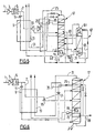
- FIGS. 1 to 6 are schematic representations of installations according to the invention.
- the air 1 is compressed in the compressor 3, purified at 5 and divided in two.
- the fraction 7 is partially cooled in the exchanger 13 and sent to a turbine 15 in which it expands before being sent to the first column 17
- the rest of the air 9 (around 35%) is boosted in the booster 11 and passes through then the exchanger 13 where it condenses before being sent to the column, after a sub-cooling step in exchanger 35, a few trays above the turbine air injection point 15.
- the column operates at a pressure between 1.2 and 1.3 bar abs, this process can be used up to pressures of 20 bar abs, preferably less than 10 bar abs.
- Oxygen 27 is withdrawn from the bottom of the column, pressurized by the pump 23 and sent to the exchanger 13 where it vaporizes.
- Nitrogen 25 from the head of the column heats up in the sub-cooler 35 before being split in half.
- a portion 31 is sent to the exchanger 13 where it heats up.
- the rest 29 is sent to compressor 21 with an inlet temperature of -182 ° C where it is compressed to 4.9 bar before being sent to the tank reboiler 19 of the first column 17. There it condenses and is returned to the top of the column to serve as reflux 33.
- the turbine 15 is coupled to the cold compressor 21.
- Oxygen 27 is withdrawn from the bottom of the column, pressurized by the pump 23 and sent to the exchanger 13 where it vaporizes.
- the cycle nitrogen to the condenser intermediate 39 and the air 12 to the tank reboiler 19 by adjusting the pressures.
- a cold booster 21 with several stages in series, each feeding an intermediate or tank vaporizer.
- the booster cold 21 can have several stages in series each driven by a turbine or combined for example by means of a multiplier with a single turbine.
- Nitrogen 25 from the head of the column heats up in the sub-cooler 21 before being split in half.
- a portion 31 is sent to the exchanger 13 where it heats up.
- the rest 29 is sent to compressor 21 with an inlet temperature of -182 ° C where it is compressed to 4.9 bar before being sent to the tank reboiler 19 of the first column 17 (the pressure could be 4 bar if the nitrogen is sent to the intermediate reboiler). There it condenses and is returned to the top of the column to serve as reflux.
- the turbine 15 is coupled to the cold compressor 21.
- Figure 3 shows the case where the pressurized tank oxygen from the column vaporizes by direct heat exchange in a mixing column.
- the air 1 is compressed in the compressor 3, purified at 5 and divided into two.
- the fraction 7 is partially cooled in the exchanger 13 and sent to a turbine 15 in which it relaxes before being sent to the first column 17.
- the rest of air 9 (about 25%) is boosted in the booster 11 and then passes through the exchanger 13.
- the first column 17 operates at a pressure between 3 and 20 bar.
- the air flow 9 does not liquefy in the exchanger but is sent in the form carbonated in the tank of the mixing column. So the mixing column operates at a higher pressure than first column 17. We can consider operating both columns at the same pressure or operate the mixing column at the lowest pressure.
- the mixing column is supplied at the head with oxygen pumped from the tank of the first column 17 but can be supplied at the head by another flow less rich in oxygen than the flow pumped or in the tank by air from a source other than compressor 1.
- Nitrogen 25 from the head of the column heats up in the sub-cooler 21 before being split in half.
- a portion 31 is sent to the exchanger 13 where it heats up.
- the rest 29 is sent to compressor 21 with an inlet temperature of -182 ° C where it is compressed to 4.9 bar before being sent to the tank reboiler 19 of column 17. There it condenses and is returned to the top of the column to serve as reflux.
- the turbine 15 is coupled to the cold compressor 21.
- an exchanger 49 heats the pumped oxygen sent to the head of the column mixing 47.
- the intermediate liquid flow from the mixing column is sent to the column 17 and the impure oxygen 48 withdrawn at the head of this one is sent to the exchanger 13.
- FIG. 4 illustrates the case where a flow enriched in argon of the column 17 feeds a mixture column 57 having a cooled head condenser 51 by an intermediate liquid from the first column 17. A fluid enriched in argon is withdrawn at the head of the mixture column 57.
- Nitrogen 25 from the head of the column heats up in the sub-cooler 21 before being split in half.
- a portion 31 is sent to the exchanger 13 where it heats up.
- the rest 29 is sent to compressor 21 with an inlet temperature of -182 ° C where it is compressed to 4.9 bar before being sent to the tank reboiler 19 of the first column 17. There it condenses and is returned to the top of the column to serve reflux.
- the turbine 15 is coupled to the cold compressor 21.
- Oxygen 27 is withdrawn from the bottom of the column, pressurized by the pump 23 and sent to the exchanger 13 where it vaporizes.
- Figure 5 shows a Etienne 67 column supplied to the tank by a flow liquid drawn off a few trays below the air injection point 9 and at the same level that the blown air 7. This liquid is pressurized by the pump 63 before being sent to the Etienne column. The liquid formed at the top of the Etienne 67 column is sent in head of the first column 17.
- the Etienne column operating at 2.5 bar has an overhead condenser 61 cooled by part of the tank liquid 65 from the same column, the rest of the liquid being sent to column 17 below the point of injection of the blown air 7.
- the expanded liquid vaporizes in the condenser 61 before being sent some trays above the condenser 19 of column 17.
- Nitrogen 25 from the head of the column heats up in the sub-cooler 21 before being split in half.
- a portion 31 is sent to the exchanger 13 where it heats up.
- the rest 29 is sent to compressor 21 with an inlet temperature of -182 ° C where it is compressed to 4.9 bar before being sent to reboilers 19.69 columns 17.67 respectively.
- reboilers 19.69 columns 17.67 respectively.
- the turbine 15 is coupled to the compressor cold 21.
- Oxygen 27 is withdrawn from the bottom of the column, pressurized by the pump 23 and sent to the exchanger 13 where it vaporizes.
- an air flow 7 is expanded in a turbine 15 and sent to the middle of the first column 19 operating between 1.5 and 20 bar.
- a gas 25 of the first column is heated in the sub-cooler 35, compressed in the cold compressor 21 and sent as the sole supply to the tank of a second column 77, operating at higher pressure than the first column.
- the head of the second column 77 is connected with the tank of the first column 17 by means of a reboiler 19.
- a flow rate liquid nitrogen 78 is withdrawn at the head of the second column.
- the air flow 9 is overpressed and used to vaporize liquid oxygen.
- the compressed gas in the cold compressor 21 is enriched with nitrogen before to be sent to reboiler 19.
- Other means of enrichment, such as membrane can be provided.
- the liquid in the second column is expanded and sent to the first column at the gas withdrawal level 25 to be compressed in the cold compressor 21.
- a gas 31 richer in nitrogen than gas 25 is withdrawn from the device.
Landscapes
- Engineering & Computer Science (AREA)
- Physics & Mathematics (AREA)
- Mechanical Engineering (AREA)
- Thermal Sciences (AREA)
- General Engineering & Computer Science (AREA)
- Health & Medical Sciences (AREA)
- Emergency Medicine (AREA)
- Separation By Low-Temperature Treatments (AREA)
Abstract
Description
- comprimer de l'air, l'épurer et en envoyer au moins une partie à une première (la) colonne ;
- séparer à température cryogénique de l'air dans la colonne ;
- comprimer au moins une partie d'une fraction contenant au plus 30 % molaires d'oxygène extraite de la colonne dans un compresseur dont la température d'aspiration est inférieure à la température ambiante ;
- refroidir au moins partiellement ladite fraction comprimée et la condenser en vaporisant un fluide interne ou extrait de la première colonne, et éventuellement après l'avoir enrichie en azote ; et,
- extraire une fraction liquide riche en oxygène de la première colonne, la pressuriser à une pression supérieure à celle de la colonne et la vaporiser par échange de chaleur direct ou indirect avec une partie de l'air d'alimentation pour former un produit gazeux sous pression riche en oxygène.
- on soutire un produit gazeux riche an azote en tête de la première (la) colonne ;
- on comprime une fraction contenant au plus 30 % molaires d'oxygène extraite de la colonne dans un compresseur dont la température d'aspiration est inférieure à la température ambiante à une pression inférieure à 30 bar ab ;
- la pression de la première (la) colonne est entre 1,3 et 20 bar abs, de préférence entre 3 et 10 bar abs;
- la fraction comprimée contient au plus 19% molaires d'oxygène et au moins 81% molaires d'azote, de préférence au moins 90% molaires d'azote ;
- au moins une partie de l'air est détendue dans une turbine avant de l'envoyer à la première (la) colonne ;
- la production de travail par la détente d'au moins une partie de l'air sert au moins partiellement à comprimer la fraction contenant au plus 30 % d'oxygène en un ou plusieurs étage(s) de compression ;
- au moins une partie de l'air est comprimée à une haute pression, condensée et envoyée à la première (la ) colonne ;
- une partie non-détendue de l'air est condensée en vaporisant un fluide interne ou extrait de la première colonne (Fig. 2) ;
- la vaporisation de la fraction liquide riche en oxygène s'effectue par contact direct dans une colonne auxiliaire dite de mélange (Fig. 3);
- une colonne auxiliaire destinée à la production d'argon est alimentée à partir de la première colonne (Fig. 4) ;
- on distille dans une colonne auxiliaire un liquide enrichi en oxygène extrait de la simple colonne pour produire une fraction plus riche en oxygène et une fraction appauvrie en oxygène réintroduites dans la première colonne (Fig. 5) ;
- au moins une partie de l'air destiné à une colonne de l'appareil vient du compresseur d'une turbine à gaz et/ou un gaz enrichi en azote provenant de la première (la) colonne est renvoyé au système de la turbine à gaz ;
- la pression d'entrée de la turbine à gaz est supérieure à 15 bar abs ;
- la pureté de l'oxygène gazeux produit est au moins 80% molaires, de préférence au moins 90% molaires ;
- la température d'aspiration du compresseur froid est inférieure à -100 °C ou de préférence inférieure à -150 °C ;
- on produit ou on ne produit pas de liquide comme produit final ;
- la fraction comprimée se condense au moins partiellement dans le rebouilleur de cuve de la première (la) colonne ;
- le débit d'air qui sert à vaporiser le liquide riche en oxygène se condense au moins partiellement et est envoyé à la première colonne ;
- la fraction comprimée s'enrichit en azote dans une colonne de distillation reliée thermiquement avec la première colonne.
- l'appareil comprend une turbine alimentée par de l'air et la sortie de la turbine est reliée à la première colonne;
- le liquide pressurisé se vaporise dans une colonne de mélange ;
- l'appareil comprend une colonne de production d'argon alimentée à partir de la première colonne ayant un rebouilleur de cuve ;
- la colonne ayant un rebouilleur de cuve a au moins un condenseur intermédiaire ;
- la colonne ayant un rebouilleur de cuve n'a pas de condenseur de tête
- il y a une deuxième colonne reliée thermiquement avec la première colonne, éventuellement comprenant des moyens pour envoyer le gaz de tête de la deuxième colonne au rebouilleur de cuve (19).
- il y a des moyens pour envoyer le gaz comprimé dans le compresseur (21) en cuve de a deuxième colonne.
Claims (24)
- Procédé de séparation de l'air par distillation cryogénique dans un appareil comprenant au moins une colonne (17,47,57,77) comprenant les étapes de :comprimer de l'air, l'épurer et en envoyer au moins une partie (7,9) à une première (la) colonne (17);séparer à température cryogénique de l'air dans la colonne ;comprimer au moins une partie d'une fraction (25) contenant au plus 30 % molaires d'oxygène extraite de la colonne dans un compresseur (21) dont la température d'aspiration est inférieure à la température ambiante ;refroidir au moins partiellement ladite fraction comprimée et la condenser en vaporisant un fluide interne ou extrait de la première colonne ; et éventuellement après l'avoir enrichie en azote, et,extraire une fraction liquide (33) riche en oxygène de la première colonne, la pressuriser à une pression supérieure à celle de la colonne (17) et la vaporiser par échange de chaleur direct ou indirect avec une partie de l'air (7,9) d'alimentation pour former un produit gazeux sous pression riche en oxygène.
- Procédé selon la revendication 1 dans lequel la fraction comprimée (25) contient au plus 19% molaires d'oxygène et au moins 81% molaires d'azote.
- Procédé selon l'une des revendications 1 et 2 dans lequel au moins une partie (7) de l'air est détendue dans une turbine (15) avant de l'envoyer à la première (la) colonne.
- Procédé selon la revendication 3 dans lequel la production de travail par la détente d'au moins une partie de l'air sert au moins partiellement à comprimer la fraction contenant au plus 30 % d'oxygène en un ou plusieurs étage de compression.
- Procédé selon la revendication 1,2 ,3 ou 4 dans lequel au moins une partie de l'air (9) est comprimée à une haute pression, condensée et envoyée à la première (la) colonne.
- Procédé selon la revendication 5 dans lequel une partie non-détendue de l'air est condensée en vaporisant un fluide interne ou extrait de la première colonne (Fig. 1,2).
- Procédé selon la revendication 1 à 6 dans lequel la vaporisation de la fraction liquide riche en oxygène s'effectue par contact direct dans une colonne auxiliaire dite de mélange (47)(Fig. 3).
- Procédé selon l'une des revendications 1 à 7 dans lequel une colonne auxiliaire (57) destinée à la production d'argon est alimentée à partir de la première colonne. (Fig. 4).
- Procédé selon l'une des revendications 1à 8 dans lequel on distille dans une colonne auxiliaire un liquide enrichi en oxygène extrait de la simple colonne pour produire une fraction plus riche en oxygène et une fraction appauvrie en oxygène réintroduites dans la première colonne (Fig. 5).
- Procédé selon l'une des revendications 1 à 9 dans lequel au moins une partie de l'air destiné à une colonne de l'appareil vient du compresseur d'une turbine à gaz et/ou un gaz enrichi en azote provenant de la première (la) colonne est renvoyé au système de la turbine à gaz.
- Procédé selon la revendication 10 dans lequel la pression d'entrée de la turbine à gaz est supérieure à 15 bar abs.
- Procédé selon l'une des revendications 1 à 11 dans lequel la température d'aspiration du compresseur froid (21) est inférieure à -100 °C.
- Procédé selon la revendication 12 dans lequel la température d'aspiration du compresseur froid (21) est inférieure à -150 °C.
- Procédé selon l'une des revendications 1 à 13 dans lequel on produit ou on ne produit pas de liquide (78) comme produit final.
- Procédé selon l'une des revendications 1 à 14 dans lequel la fraction comprimée se condense au moins partiellement dans le rebouilleur de cuve (19) de la première (la) colonne.
- Procédé selon l'une des revendications précédentes dans lequel la fraction comprimée s'enrichit en azote dans une deuxième colonne de distillation (77) reliée thermiquement avec la première colonne (Fig 6).
- Installation de séparation d'air par distillation dans au moins une première colonne (17) ayant un rebouilleur de cuve (19) comprenant des moyens (7) pour envoyer de l'air comprimé et épuré à la première (la) colonne, un compresseur (21) pour comprimer un gaz (25) contenant au plus 30% molaires d'oxygène provenant de la colonne ayant une température d'entrée au plus 5°C plus chaude d'une température de la première (la) colonne, des moyens pour envoyer le gaz comprimé au rebouilleur de cuve, des moyens (33) pour renvoyer le gaz comprimé au moins partiellement condensé dans le rebouilleur de cuve (19) à la colonne, éventuellement des moyens pour enrichir le gaz comprimé en azote en amont du rebouilleur, des moyens (27) pour soutirer un liquide enrichi en oxygène en cuve de la colonne, des moyens (23) pour le pressuriser et des moyens (13,47) pour vaporiser le liquide pressurisé par échange de chaleur direct ou indirect caractérisé en ce qu'elle comprend des moyens pour vaporiser le liquide pressurisé par échange de chaleur direct ou indirect et si l'échange est indirect l'échange de chaleur se fait avec de l'air (9) destiné à la première colonne.
- Installation selon la revendication 17 comprenant une turbine de détente d'air (15) et dans laquelle la sortie de la turbine est reliée à la première (la) colonne.
- Installation selon une des revendications 17 et 18 dans laquelle le liquide pressurisé se vaporise dans une colonne de mélange (47).
- Installation selon une des revendications 17 à 19 comprenant une colonne de production d'argon (57) alimentée à partir de la colonne (17) ayant un rebouilleur de cuve (19).
- Installation selon une des revendications 17 à 20 dans laquelle la colonne (17) ayant un rebouilleur de cuve (19) a au moins un condenseur intermédiaire (39).
- Installation selon une des revendications 17 à 21 dans laquelle la colonne (17) ayant un rebouilleur de cuve (19) n'a pas de condenseur de tête.
- Installation selon l'une des revendications 17 à 22, comprenant une deuxième colonne (77) reliée thermiquement avec la première colonne, éventuellement comprenant des moyens pour envoyer le gaz de tête de la deuxième colonne au rebouilleur de cuve (19) (Fig 6).
- Installation selon la revendication 23 comprenant des moyens pour envoyer le gaz comprimé dans le compresseur (21) en cuve de la deuxième colonne (77).
Applications Claiming Priority (2)
| Application Number | Priority Date | Filing Date | Title |
|---|---|---|---|
| FR0002924A FR2806152B1 (fr) | 2000-03-07 | 2000-03-07 | Procede et installation de separation d'air par distillation cryogenique |
| FR0002924 | 2000-03-07 |
Publications (2)
| Publication Number | Publication Date |
|---|---|
| EP1132700A1 true EP1132700A1 (fr) | 2001-09-12 |
| EP1132700B1 EP1132700B1 (fr) | 2005-10-26 |
Family
ID=8847820
Family Applications (1)
| Application Number | Title | Priority Date | Filing Date |
|---|---|---|---|
| EP01400413A Expired - Lifetime EP1132700B1 (fr) | 2000-03-07 | 2001-02-16 | Procédé et installation de séparation d'air par distillation cryogénique |
Country Status (8)
| Country | Link |
|---|---|
| US (1) | US6484534B2 (fr) |
| EP (1) | EP1132700B1 (fr) |
| AR (1) | AR027970A1 (fr) |
| BR (1) | BR0102482A (fr) |
| CA (1) | CA2339392A1 (fr) |
| DE (1) | DE60114269T2 (fr) |
| ES (1) | ES2252164T3 (fr) |
| FR (1) | FR2806152B1 (fr) |
Cited By (2)
| Publication number | Priority date | Publication date | Assignee | Title |
|---|---|---|---|---|
| CN101922848A (zh) * | 2009-06-16 | 2010-12-22 | 普莱克斯技术有限公司 | 用于产生加压产物的方法和设备 |
| WO2012155318A1 (fr) * | 2011-05-13 | 2012-11-22 | L'air Liquide, Societe Anonyme Pour L'etude Et L'exploitation Des Procedes Georges Claude | Procédé et appareil de production d'oxygène à haute pression par distillation cryogénique |
Families Citing this family (4)
| Publication number | Priority date | Publication date | Assignee | Title |
|---|---|---|---|---|
| FR2830928B1 (fr) * | 2001-10-17 | 2004-03-05 | Air Liquide | Procede de separation d'air par distillation cryogenique et une installation pour la mise en oeuvre de ce procede |
| US7296437B2 (en) * | 2002-10-08 | 2007-11-20 | L'air Liquide, Societe Anonyme A Directoire Et Conseil De Surveillance Pour L'etude Et L'exploitation Des Procedes Georges Claude | Process for separating air by cryogenic distillation and installation for implementing this process |
| JP2007512846A (ja) * | 2003-12-04 | 2007-05-24 | ゼンコー・インコーポレイテッド | 増加した宿主ストリング含有量を有する変異体タンパク質の生成方法およびその組成物 |
| EP1767884A1 (fr) * | 2005-09-23 | 2007-03-28 | L'Air Liquide Société Anon. à Directoire et Conseil de Surveillance pour l'Etude et l'Exploitation des Procédés Georges Claude | Procédé et dispositif pour la séparation cryogénique d'air |
Citations (5)
| Publication number | Priority date | Publication date | Assignee | Title |
|---|---|---|---|---|
| DE1199293B (de) * | 1963-03-29 | 1965-08-26 | Linde Eismasch Ag | Verfahren und Vorrichtung zur Luftzerlegung in einem Einsaeulenrektifikator |
| US3392536A (en) * | 1966-09-06 | 1968-07-16 | Air Reduction | Recompression of mingled high air separation using dephlegmator pressure and compressed low pressure effluent streams |
| EP0589646A1 (fr) * | 1992-09-23 | 1994-03-30 | Air Products And Chemicals, Inc. | Procédé de distillation pour la production d'azote dépourvu de monoxyde de carbone |
| US5596885A (en) * | 1994-06-20 | 1997-01-28 | L'air Liquide, Societe Anonyme Pour L'etude Et L'exploitation Des Procedes Georges Claude | Process and installation for the production of gaseous oxygen under pressure |
| EP0810412A2 (fr) * | 1996-05-29 | 1997-12-03 | Teisan Kabushiki Kaisha | Installation et procédé de génération d'azote de haute pureté |
Family Cites Families (3)
| Publication number | Priority date | Publication date | Assignee | Title |
|---|---|---|---|---|
| US5379599A (en) * | 1993-08-23 | 1995-01-10 | The Boc Group, Inc. | Pumped liquid oxygen method and apparatus |
| US5832748A (en) * | 1996-03-19 | 1998-11-10 | Praxair Technology, Inc. | Single column cryogenic rectification system for lower purity oxygen production |
| US6082135A (en) * | 1999-01-29 | 2000-07-04 | The Boc Group, Inc. | Air separation method and apparatus to produce an oxygen product |
-
2000
- 2000-03-07 FR FR0002924A patent/FR2806152B1/fr not_active Expired - Fee Related
-
2001
- 2001-02-16 EP EP01400413A patent/EP1132700B1/fr not_active Expired - Lifetime
- 2001-02-16 DE DE60114269T patent/DE60114269T2/de not_active Expired - Lifetime
- 2001-02-16 ES ES01400413T patent/ES2252164T3/es not_active Expired - Lifetime
- 2001-03-05 CA CA002339392A patent/CA2339392A1/fr not_active Abandoned
- 2001-03-06 AR ARP010101047A patent/AR027970A1/es unknown
- 2001-03-07 US US09/799,735 patent/US6484534B2/en not_active Expired - Lifetime
- 2001-03-07 BR BR0102482-5A patent/BR0102482A/pt active Search and Examination
Patent Citations (5)
| Publication number | Priority date | Publication date | Assignee | Title |
|---|---|---|---|---|
| DE1199293B (de) * | 1963-03-29 | 1965-08-26 | Linde Eismasch Ag | Verfahren und Vorrichtung zur Luftzerlegung in einem Einsaeulenrektifikator |
| US3392536A (en) * | 1966-09-06 | 1968-07-16 | Air Reduction | Recompression of mingled high air separation using dephlegmator pressure and compressed low pressure effluent streams |
| EP0589646A1 (fr) * | 1992-09-23 | 1994-03-30 | Air Products And Chemicals, Inc. | Procédé de distillation pour la production d'azote dépourvu de monoxyde de carbone |
| US5596885A (en) * | 1994-06-20 | 1997-01-28 | L'air Liquide, Societe Anonyme Pour L'etude Et L'exploitation Des Procedes Georges Claude | Process and installation for the production of gaseous oxygen under pressure |
| EP0810412A2 (fr) * | 1996-05-29 | 1997-12-03 | Teisan Kabushiki Kaisha | Installation et procédé de génération d'azote de haute pureté |
Cited By (3)
| Publication number | Priority date | Publication date | Assignee | Title |
|---|---|---|---|---|
| CN101922848A (zh) * | 2009-06-16 | 2010-12-22 | 普莱克斯技术有限公司 | 用于产生加压产物的方法和设备 |
| CN101922848B (zh) * | 2009-06-16 | 2015-03-18 | 普莱克斯技术有限公司 | 用于产生加压产物的方法和设备 |
| WO2012155318A1 (fr) * | 2011-05-13 | 2012-11-22 | L'air Liquide, Societe Anonyme Pour L'etude Et L'exploitation Des Procedes Georges Claude | Procédé et appareil de production d'oxygène à haute pression par distillation cryogénique |
Also Published As
| Publication number | Publication date |
|---|---|
| AR027970A1 (es) | 2003-04-16 |
| US20020134105A1 (en) | 2002-09-26 |
| EP1132700B1 (fr) | 2005-10-26 |
| BR0102482A (pt) | 2001-10-16 |
| US6484534B2 (en) | 2002-11-26 |
| FR2806152A1 (fr) | 2001-09-14 |
| ES2252164T3 (es) | 2006-05-16 |
| DE60114269D1 (de) | 2005-12-01 |
| CA2339392A1 (fr) | 2001-09-07 |
| FR2806152B1 (fr) | 2002-08-30 |
| DE60114269T2 (de) | 2006-07-20 |
Similar Documents
| Publication | Publication Date | Title |
|---|---|---|
| EP0713069B1 (fr) | Procédé et installation de séparation d'air | |
| EP0689019B1 (fr) | Procédé et installation de production d'oxygène gazeux sous pression | |
| EP2122282B1 (fr) | Procédé de séparation d'un mélange de monoxyde de carbone, de méthane, d'hydrogène et d'azote par distillation cryogénique | |
| JP4728219B2 (ja) | 空気の低温蒸留により加圧空気ガスを製造するための方法及びシステム | |
| FR2990500A1 (fr) | Procede et appareil de separation d'air par distillation cryogenique | |
| JPH10227560A (ja) | 空気分離方法 | |
| EP1014020B1 (fr) | Procédé de séparation cryogénique des gaz de l'air | |
| CA2119597A1 (fr) | Procd et installation de production d'oxygne gazeux et/ou d'azote gazeux sous pression par distillation d'air | |
| EP3631327A1 (fr) | Procédé et appareil pour la séparation de l'air par distillation cryogénique | |
| EP2694898B1 (fr) | Procédé et appareil de séparation d'air par distillation cryogénique | |
| EP1189003B1 (fr) | Procédé et installation de séparation d'air par distillation cryogénique | |
| US20110041552A1 (en) | Apparatus And Method For Separating Air By Cryogenic Distillation | |
| FR3150578A3 (fr) | Procédé et appareil de séparation d’air par distillation cryogénique | |
| JP2009509120A (ja) | 低温蒸留による空気の分離方法及び装置。 | |
| EP1132700B1 (fr) | Procédé et installation de séparation d'air par distillation cryogénique | |
| FR2831249A1 (fr) | Procede et installation de separation d'air par distillation cryogenique | |
| US20040244416A1 (en) | Method for separating air by cryogenic distillation and installation therefor | |
| EP3058297B1 (fr) | Procédé et appareil de séparation d'air par distillation cryogénique | |
| FR2787559A1 (fr) | Procede et installation de separation d'air par distillation cryogenique | |
| EP0612967A1 (fr) | Procédé et installation de production d'oxygène et/ou d'azote sous pression | |
| EP1063485B1 (fr) | Appareil et procédé de séparation d'air par distillation cryogénique | |
| FR2787561A1 (fr) | Procede de separation d'air par distillation cryogenique | |
| FR3135134A1 (fr) | Procédé d’augmentation de la capacité d’un appareil de séparation d’air par distillation cryogénique existant et appareil de séparation d’air | |
| FR2864213A1 (fr) | Procede et installation de production sous forme gazeuse et sous haute pression d'au moins un fluide choisi parmi l'oxygene, l'argon et l'azote par distillation cryogenique de l'air | |
| FR3110685A1 (fr) | Procédé et appareil de séparation d’air par distillation cryogénique |
Legal Events
| Date | Code | Title | Description |
|---|---|---|---|
| PUAI | Public reference made under article 153(3) epc to a published international application that has entered the european phase |
Free format text: ORIGINAL CODE: 0009012 |
|
| AK | Designated contracting states |
Kind code of ref document: A1 Designated state(s): DE ES FI FR GB SE Kind code of ref document: A1 Designated state(s): AT BE CH CY DE DK ES FI FR GB GR IE IT LI LU MC NL PT SE TR |
|
| AX | Request for extension of the european patent |
Free format text: AL;LT;LV;MK;RO;SI |
|
| RAP1 | Party data changed (applicant data changed or rights of an application transferred) |
Owner name: L'AIR LIQUIDE, S.A. A DIRECTOIRE ET CONSEIL DE SUR |
|
| 17P | Request for examination filed |
Effective date: 20020312 |
|
| AKX | Designation fees paid |
Free format text: DE ES FI FR GB SE |
|
| 17Q | First examination report despatched |
Effective date: 20030718 |
|
| GRAP | Despatch of communication of intention to grant a patent |
Free format text: ORIGINAL CODE: EPIDOSNIGR1 |
|
| GRAS | Grant fee paid |
Free format text: ORIGINAL CODE: EPIDOSNIGR3 |
|
| GRAA | (expected) grant |
Free format text: ORIGINAL CODE: 0009210 |
|
| AK | Designated contracting states |
Kind code of ref document: B1 Designated state(s): DE ES FI FR GB SE |
|
| PG25 | Lapsed in a contracting state [announced via postgrant information from national office to epo] |
Ref country code: FI Free format text: LAPSE BECAUSE OF FAILURE TO SUBMIT A TRANSLATION OF THE DESCRIPTION OR TO PAY THE FEE WITHIN THE PRESCRIBED TIME-LIMIT Effective date: 20051026 |
|
| REG | Reference to a national code |
Ref country code: GB Ref legal event code: FG4D Free format text: NOT ENGLISH |
|
| REF | Corresponds to: |
Ref document number: 60114269 Country of ref document: DE Date of ref document: 20051201 Kind code of ref document: P |
|
| PG25 | Lapsed in a contracting state [announced via postgrant information from national office to epo] |
Ref country code: SE Free format text: LAPSE BECAUSE OF FAILURE TO SUBMIT A TRANSLATION OF THE DESCRIPTION OR TO PAY THE FEE WITHIN THE PRESCRIBED TIME-LIMIT Effective date: 20060126 |
|
| GBT | Gb: translation of ep patent filed (gb section 77(6)(a)/1977) |
Effective date: 20060116 |
|
| REG | Reference to a national code |
Ref country code: ES Ref legal event code: FG2A Ref document number: 2252164 Country of ref document: ES Kind code of ref document: T3 |
|
| PLBE | No opposition filed within time limit |
Free format text: ORIGINAL CODE: 0009261 |
|
| STAA | Information on the status of an ep patent application or granted ep patent |
Free format text: STATUS: NO OPPOSITION FILED WITHIN TIME LIMIT |
|
| 26N | No opposition filed |
Effective date: 20060727 |
|
| PGFP | Annual fee paid to national office [announced via postgrant information from national office to epo] |
Ref country code: FR Payment date: 20110302 Year of fee payment: 11 |
|
| PGFP | Annual fee paid to national office [announced via postgrant information from national office to epo] |
Ref country code: ES Payment date: 20110228 Year of fee payment: 11 Ref country code: GB Payment date: 20110217 Year of fee payment: 11 |
|
| GBPC | Gb: european patent ceased through non-payment of renewal fee |
Effective date: 20120216 |
|
| REG | Reference to a national code |
Ref country code: FR Ref legal event code: ST Effective date: 20121031 |
|
| PG25 | Lapsed in a contracting state [announced via postgrant information from national office to epo] |
Ref country code: FR Free format text: LAPSE BECAUSE OF NON-PAYMENT OF DUE FEES Effective date: 20120229 Ref country code: GB Free format text: LAPSE BECAUSE OF NON-PAYMENT OF DUE FEES Effective date: 20120216 |
|
| REG | Reference to a national code |
Ref country code: ES Ref legal event code: FD2A Effective date: 20130708 |
|
| PG25 | Lapsed in a contracting state [announced via postgrant information from national office to epo] |
Ref country code: ES Free format text: LAPSE BECAUSE OF NON-PAYMENT OF DUE FEES Effective date: 20120217 |
|
| PGFP | Annual fee paid to national office [announced via postgrant information from national office to epo] |
Ref country code: DE Payment date: 20140219 Year of fee payment: 14 |
|
| REG | Reference to a national code |
Ref country code: DE Ref legal event code: R119 Ref document number: 60114269 Country of ref document: DE |
|
| PG25 | Lapsed in a contracting state [announced via postgrant information from national office to epo] |
Ref country code: DE Free format text: LAPSE BECAUSE OF NON-PAYMENT OF DUE FEES Effective date: 20150901 |