EP1132690B1 - Vorrichtung zur Temperierung und/oder Belüftung eines Raumes - Google Patents
Vorrichtung zur Temperierung und/oder Belüftung eines Raumes Download PDFInfo
- Publication number
- EP1132690B1 EP1132690B1 EP01103816A EP01103816A EP1132690B1 EP 1132690 B1 EP1132690 B1 EP 1132690B1 EP 01103816 A EP01103816 A EP 01103816A EP 01103816 A EP01103816 A EP 01103816A EP 1132690 B1 EP1132690 B1 EP 1132690B1
- Authority
- EP
- European Patent Office
- Prior art keywords
- air
- heat exchanger
- pass
- exhaust air
- exhaust
- Prior art date
- Legal status (The legal status is an assumption and is not a legal conclusion. Google has not performed a legal analysis and makes no representation as to the accuracy of the status listed.)
- Expired - Lifetime
Links
- 238000005496 tempering Methods 0.000 title claims description 4
- 238000011084 recovery Methods 0.000 claims description 36
- 238000010438 heat treatment Methods 0.000 claims description 11
- 238000001816 cooling Methods 0.000 claims description 10
- 238000011144 upstream manufacturing Methods 0.000 claims description 4
- 230000003134 recirculating effect Effects 0.000 abstract description 9
- 238000009423 ventilation Methods 0.000 abstract description 4
- 238000009434 installation Methods 0.000 abstract description 3
- 238000004378 air conditioning Methods 0.000 abstract 1
- 230000008901 benefit Effects 0.000 description 3
- 230000007423 decrease Effects 0.000 description 3
- 238000013461 design Methods 0.000 description 3
- 238000010586 diagram Methods 0.000 description 3
- 230000001143 conditioned effect Effects 0.000 description 2
- 238000010276 construction Methods 0.000 description 2
- 239000011521 glass Substances 0.000 description 2
- 230000017525 heat dissipation Effects 0.000 description 2
- 238000004519 manufacturing process Methods 0.000 description 2
- 230000000149 penetrating effect Effects 0.000 description 2
- 230000009467 reduction Effects 0.000 description 2
- 230000004913 activation Effects 0.000 description 1
- 230000033228 biological regulation Effects 0.000 description 1
- 230000008859 change Effects 0.000 description 1
- 238000005253 cladding Methods 0.000 description 1
- 230000001427 coherent effect Effects 0.000 description 1
- 238000011161 development Methods 0.000 description 1
- 230000003670 easy-to-clean Effects 0.000 description 1
- 238000009413 insulation Methods 0.000 description 1
- 239000000203 mixture Substances 0.000 description 1
- 238000012986 modification Methods 0.000 description 1
- 230000004048 modification Effects 0.000 description 1
- 238000012549 training Methods 0.000 description 1
- 238000012546 transfer Methods 0.000 description 1
- 230000007704 transition Effects 0.000 description 1
- XLYOFNOQVPJJNP-UHFFFAOYSA-N water Substances O XLYOFNOQVPJJNP-UHFFFAOYSA-N 0.000 description 1
Images



Classifications
-
- F—MECHANICAL ENGINEERING; LIGHTING; HEATING; WEAPONS; BLASTING
- F24—HEATING; RANGES; VENTILATING
- F24F—AIR-CONDITIONING; AIR-HUMIDIFICATION; VENTILATION; USE OF AIR CURRENTS FOR SCREENING
- F24F7/00—Ventilation
- F24F7/04—Ventilation with ducting systems, e.g. by double walls; with natural circulation
- F24F7/06—Ventilation with ducting systems, e.g. by double walls; with natural circulation with forced air circulation, e.g. by fan positioning of a ventilator in or against a conduit
- F24F7/08—Ventilation with ducting systems, e.g. by double walls; with natural circulation with forced air circulation, e.g. by fan positioning of a ventilator in or against a conduit with separate ducts for supplied and exhausted air with provisions for reversal of the input and output systems
-
- F—MECHANICAL ENGINEERING; LIGHTING; HEATING; WEAPONS; BLASTING
- F24—HEATING; RANGES; VENTILATING
- F24D—DOMESTIC- OR SPACE-HEATING SYSTEMS, e.g. CENTRAL HEATING SYSTEMS; DOMESTIC HOT-WATER SUPPLY SYSTEMS; ELEMENTS OR COMPONENTS THEREFOR
- F24D19/00—Details
- F24D19/008—Details related to central heating radiators
- F24D19/0085—Fresh air entries for air entering the room to be heated by the radiator
-
- F—MECHANICAL ENGINEERING; LIGHTING; HEATING; WEAPONS; BLASTING
- F24—HEATING; RANGES; VENTILATING
- F24F—AIR-CONDITIONING; AIR-HUMIDIFICATION; VENTILATION; USE OF AIR CURRENTS FOR SCREENING
- F24F12/00—Use of energy recovery systems in air conditioning, ventilation or screening
- F24F12/001—Use of energy recovery systems in air conditioning, ventilation or screening with heat-exchange between supplied and exhausted air
- F24F12/006—Use of energy recovery systems in air conditioning, ventilation or screening with heat-exchange between supplied and exhausted air using an air-to-air heat exchanger
-
- F—MECHANICAL ENGINEERING; LIGHTING; HEATING; WEAPONS; BLASTING
- F24—HEATING; RANGES; VENTILATING
- F24F—AIR-CONDITIONING; AIR-HUMIDIFICATION; VENTILATION; USE OF AIR CURRENTS FOR SCREENING
- F24F7/00—Ventilation
- F24F2007/0025—Ventilation using vent ports in a wall
-
- F—MECHANICAL ENGINEERING; LIGHTING; HEATING; WEAPONS; BLASTING
- F24—HEATING; RANGES; VENTILATING
- F24F—AIR-CONDITIONING; AIR-HUMIDIFICATION; VENTILATION; USE OF AIR CURRENTS FOR SCREENING
- F24F11/00—Control or safety arrangements
- F24F11/0001—Control or safety arrangements for ventilation
- F24F2011/0006—Control or safety arrangements for ventilation using low temperature external supply air to assist cooling
-
- F—MECHANICAL ENGINEERING; LIGHTING; HEATING; WEAPONS; BLASTING
- F24—HEATING; RANGES; VENTILATING
- F24F—AIR-CONDITIONING; AIR-HUMIDIFICATION; VENTILATION; USE OF AIR CURRENTS FOR SCREENING
- F24F12/00—Use of energy recovery systems in air conditioning, ventilation or screening
- F24F12/001—Use of energy recovery systems in air conditioning, ventilation or screening with heat-exchange between supplied and exhausted air
- F24F2012/007—Use of energy recovery systems in air conditioning, ventilation or screening with heat-exchange between supplied and exhausted air using a by-pass for bypassing the heat-exchanger
-
- Y—GENERAL TAGGING OF NEW TECHNOLOGICAL DEVELOPMENTS; GENERAL TAGGING OF CROSS-SECTIONAL TECHNOLOGIES SPANNING OVER SEVERAL SECTIONS OF THE IPC; TECHNICAL SUBJECTS COVERED BY FORMER USPC CROSS-REFERENCE ART COLLECTIONS [XRACs] AND DIGESTS
- Y02—TECHNOLOGIES OR APPLICATIONS FOR MITIGATION OR ADAPTATION AGAINST CLIMATE CHANGE
- Y02B—CLIMATE CHANGE MITIGATION TECHNOLOGIES RELATED TO BUILDINGS, e.g. HOUSING, HOUSE APPLIANCES OR RELATED END-USER APPLICATIONS
- Y02B30/00—Energy efficient heating, ventilation or air conditioning [HVAC]
- Y02B30/56—Heat recovery units
Definitions
- Such a device for which the term “decentralized balustrade device” is also common is known for example from DE 87 00 632 U1.
- the vacuumed near the ceiling Exhaust air is conducted there via a heat exchanger for heat recovery and then emitted to the environment by an exhaust air fan as exhaust air.
- the outside air sucked in by an outside air inlet from an outside air fan arranged behind it and then passed over the heat exchanger for heat recovery, in order to then in a heating or cooling element after-heating as required and ultimately as supply air to be delivered to the room to be tempered or ventilated.
- the air duct leading the exhaust air to the heat exchanger for heat recovery a branch from which the exhaust air without further treatment as so-called recirculating air directly the supply air flow can be supplied before the heating and / or cooling element.
- a separate circulating air fan is arranged in this circulating air bypass.
- a disadvantage of the known device is that the equipment and therefore manufacturing costs using three separate fans is also high. Is too the control engineering effort is very great, for example, while maintaining a a certain proportion of recirculated air in the supply air, the supply air volume flow is to be increased.
- the known device does not offer the possibility of outside air if necessary to lead all or part of the heat exchanger for heat recovery. Likewise, it is not provided that part of the exhaust air is not passed through the heat exchanger Conduct heat recovery. For devices, however, where this possibility exists, it proves disadvantageous that space for the aforementioned bypasses is lost goes that is not available for a larger training of the heat exchanger. Out For the greatest possible flexibility, it is therefore desirable to use both a variant the aforementioned bypasses as well as one without being able to offer them without the need for larger ones Modifications to the device are necessary.
- the invention is therefore based on the object of being as simple in construction as possible To propose a device with which different requirements can be met in a simple manner can also be met in terms of heat recovery characteristics.
- this object is achieved according to the invention solved in that an exhaust air conveyor between the exhaust air inlet and the branch of the circulating air bypass from an exhaust air duct and a supply air delivery device between an opening of the circulating air bypass into a supply air duct and the supply air outlet is arranged.
- the arrangement of the conveyor device according to the invention allows access to a third one in the circulating air bypass duct arranged conveyor are completely dispensed with.
- the invention Arrangement also has the advantage that when the delivery rate changes by the user, for example by varying the speed of the conveyor devices, both can be controlled in parallel without the distribution of the supply air volume flow changes in outside air share and recirculated air share.
- Exhaust air conveyor arranged between the first heat exchanger and the exhaust air outlet if the ratio of recirculated air to outside air changed, the output would have to be this conveyor can also be changed so that no unwanted Changes in the partial volume flows in the device result and the air balance for the Space is balanced, i.e.
- An embodiment of the device according to the invention is that the outside air over an air bypass past the first heat exchanger to the second heat exchanger is.
- Such outside air routing is particularly useful when the air volume flow required for heat dissipation is significantly greater than the outside air volume flow required for hygienic reasons. This is particularly the case for administration buildings with a normal occupancy of one person per 10 m 2 of floor space. In this case, if the cooling situation decreases, a reduction in the proportion of outside air in favor of a higher proportion of recirculating air makes sense. Only when the heat losses in the room outweigh the heat gains from internal loads, is the heat recovery started up and the outside air passed through the heat recovery heat exchanger. For this reason, it is advantageous if the ratio of the outside air volume flow through the first heat exchanger to the volume flow through the outside air bypass is adjustable.
- a further development of the device according to the invention is that a heat recovery bypass valve for the outside air, the inlet cross-section of the first one Heat exchanger or the outside air bypass blocked or a variable in the intermediate position Distribution of outside air to the first heat exchanger and outside air bypass allowed.
- a combined heat recovery bypass valve replaces two separate valves in the strand of the heat exchanger on the one hand and in the outside air bypass duct on the other hand and therefore represents a way to reduce manufacturing costs.
- the invention is further designed to provide that exhaust air via an exhaust air bypass past the first heat exchanger. Because of the good insulation of today's buildings it is usually not necessary to recover all the heat contained in the exhaust air, so that pressure relief of the exhaust air conveying device is achieved with the help of the bypass can be.
- the exhaust air bypass has an invariable cross section and opens into a duct in front of an exhaust air damper, through which exhaust air flows through the first heat exchanger is feasible.
- the object underlying the invention is further - starting from a device of the type described above - also solved in that the first heat exchanger together with the outside air bypass and / or the exhaust air bypass one as such from the Device removable unit forms.
- the entire structural unit i.e. especially the heat exchanger, and the internals that may be present in the bypasses, e.g. Flaps to be cleaned.
- the design of the aforementioned removable structural unit offers the advantage that instead of a heat exchanger combined with one or two bypass channels a heat exchanger combined with only one or with no bypass channel is used can be.
- the heat exchanger can be larger than a combination with one or more bypasses are formed, because of the one or more Bypass or bypass free space are also occupied by the heat exchanger can.
- Such a bypass-free heat exchanger unit is particularly useful in rooms with high occupancy, such as in educational institutions or meeting rooms the case is.
- air recirculation is due to the high demand for fresh air not useful, so that the supply air always consists of 100% outside air.
- Through a Exchange of the heat exchanger assembly combined with bypasses with one without Bypasses can lead a larger outside air volume flow through the heat exchanger.
- such a design allows an increase in the amount of heat recovery with pure outside air operation. To cover the energy requirements of the room, a increased amount of energy return may make sense in certain operating conditions.
- the device according to the invention is therefore characterized by great flexibility with regard to the required operating conditions. While maintaining the same basic concept can be a variant by simply replacing a single unit realize where operation with a large proportion of recirculated air makes sense (low occupancy), as well as a variant where due to a high occupancy In times of regular use, air recirculation is hardly possible and therefore a large heat recovery rate is to be aimed for.
- a particularly advantageous embodiment of the invention is that a side wall of the outside air bypass and / or the exhaust air bypass of one wall of a housing each Device and / or the heat exchanger is formed. On one or two additional ones Wall parts for forming a bypass channel can be dispensed with in this case, which is why the construction effort is further reduced and the change between a version with or is simplified without bypass channels.
- a preferred embodiment of the device according to the invention is that the Unit is cuboid and from a cuboid plate heat exchanger and one cuboidal outside air bypass and exhaust air bypass each having the same base area exists, the flows through the plate heat exchanger the outside air bypass and the exhaust air bypass in mutually parallel planes and the flows through the outdoor air bypass and enclose the exhaust air bypass by an angle of 90 °.
- the second heat exchanger has a heating register and a cooling register.
- two in an outside air nozzle There are inlet openings, one of which is air from a space between the Facade and one of these upstream outer shell and another outside air from the Sucks the outer shell surrounding environment, the effective opening cross-sections both inlet openings are adjustable independently of each other. In this way, in the Warm air, for example, between an outer glass shell of the building and the actual load-bearing building wall can be used to reheat the To be able to avoid supply air.
- Fig. 1 shows a schematic partial vertical section through a building 1, the whose outer environment 2 is delimited by a facade 3, which in turn consists of wall sections 4 and 5 window sections.
- a room 6 in building 1 is surrounded by a upper floor ceiling 7 and a lower floor ceiling 8 limited.
- a device 10 arranged for Temperature control and ventilation of the room 6 serves and in this form usually as "decentralized Parapet device "is called.
- the device 10 has an outside air inlet 11, above the outside air along the arrow 12 through a pipe socket 13 penetrating the parapet 9 into the interior of the device can be performed.
- the outside air will be closer to the device 10 later conditioned way and may be mixed with exhaust air from room 6 and then through a supply air outlet 14 in arranged on the upper side of the device 10 Delivered in the direction of arrow 15 to room 6.
- the device 10 is in the lower region provided with an exhaust air inlet 16 through which in the direction of arrow 17 exhaust air from the Room 6 is extractable.
- the exhaust air becomes either one inside the device 10
- Exhaust air outlet 18 arranged on the rear side of the device 10 is guided from there along an arrow 19 into the surroundings through a pipe socket 20 penetrating the parapet 9 2 to arrive.
- the parapet 9 is upstream of a cladding element 21, so that an air gap 22 is formed between the latter and the parapet 9.
- a Bulkheads 23 ensure that the exhaust air emerging from the upper pipe socket 20 flows upwards and not in the manner of a short circuit with the inflowing from below and can mix incoming air through the pipe socket 13.
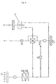
- Fig. 2 shows the circuit diagram of the device 10.
- the entering through an exhaust air inlet 16 Exhaust air (arrow 17) is first passed through a filter 24 and then reaches an exhaust air conveying device 25. Downstream of this is a branch 26, from from a partial strand through a first heat exchanger 27 and via a motor-operated Exhaust air flap 28 is guided to the exhaust air outlet, not shown, by the exhaust air (arrow 19) is released into the environment.
- Part of the exhaust air is over an exhaust air bypass 29 past the heat exchanger 27 so that the pressure loss for the exhaust air conveying device 25 can be kept low even with 100% exhaust air operation can.
- the exhaust air bypass 29 has an unchangeable cross section.
- outside air flows along the Arrow 12 through a filter 30 to then reach a branch 31. From there the Outside air either via the first heat exchanger 27 for energy recovery and via led a second heat exchanger 32 to a supply air outlet 14 for post-heating, from which the supply air enters the room according to the arrows 15.
- a circulating air bypass 37 runs to one Junction 38 in the outside air line, which makes it possible - depending on the position a recirculating air flap 39 and the exhaust air flap 28 -, exhaust air as recirculating air directly to the second Heat exchanger 32 and then feed to the supply air outlet.
- All flaps 28, 34, 35 and 39 are motor-adjustable, which also applies to valves 40 of the registers 32 ', 32 "of the second heat exchanger 32 applies.
- the temperatures of the exhaust air the outside air and the supply air can be determined continuously using temperature meters 41.
- the exhaust air conveyor 25 and the supply air conveyor 33 are in their speed, i.e. their funding, variable.
- FIG. 3 shows an alternative installation situation of the device 10 ', in which case before the Facade 3 an outer shell 42 made of glass elements arranged at a distance parallel to the latter is.
- an outer shell 42 made of glass elements arranged at a distance parallel to the latter is.
- the exhaust air connector 20 ' is in this case through the space 43 passed so that the exhaust air (arrow 19) is released into the environment 2.
- the outside air connector 13 ' has two inlet openings 44U and 44Z, each with the help a flap 45U and 45Z can be closed.
- Inlet opening 45Z corresponds to the Space 43, so that it is possible to preheated air by sunlight (arrow 46) to suck from the space 43.
- the first heat exchanger for energy recovery from the exhaust air 27 is designed as a cuboid plate heat exchanger and, on one edge standing, installed in a likewise cuboidal and horizontally arranged housing 48. From the outside air connection 11, the outside air either passes through the heat recovery flap 34 and the first heat exchanger 27 or, alternatively, via the bypass flap 35 and the exhaust air bypass 36 each to the second heat exchanger 32 and then passed through the supply air conveyor 33 into the room to be tempered.
- the exhaust air from the room becomes a (larger) one with the aid of the exhaust air conveying device 25. Part also through the first heat exchanger 27 to the exhaust air outlet 18 and one (Smaller) part, which is shown in dashed lines in Fig. 4, led to the exhaust air outlet 18.
- the ratio between the two aforementioned parts is constant in the present case.
- the recirculation flap 39 Located below the heat exchanger the recirculation flap 39, with the exhaust air from an area in front of the heat exchanger 27 in the flow of (conditioned) outside air can be mixed before it enters the second Heat exchanger 32 occurs.
- the air recirculation flap 29 can be completely closed (pure outside air operation) or to open completely, whereby when the exhaust air flap 28 and likewise closed heat recovery flap 34 and bypass flap 35 a pure one Recirculation mode results.
- FIG. 7 shows a heat exchanger 27, exhaust air bypass 29 and outside air bypass 36, overall cuboidal unit 49.
- Both the heat exchanger 27 and the exhaust air bypass 29 and the outside air bypass 36 have a cuboid shape with the same Base and are stacked one above the other or next to each other. All currents take place in planes parallel to each other.
- a combined heat recovery bypass flap 50 articulated on a side wall 51 of the assembly 49 is, more or less large portions of the outside air through the heat exchanger 27 and led the outside air bypass 36.
- the exhaust air bypass 29, which is directly connected to the heat exchanger 27 adjacent, its effective cross section is not adjustable. The volume flow ratio results from the respective flow resistances for the exhaust air flow.
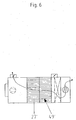
- the assembly 49 is as such as a coherent part in the housing 48 of the device usable and removable again. On the one hand, this results in the advantage of a particularly easy to clean. On the other hand, unit 49 can also be used replace such a unit 49 'shown in FIG. 6, in which both the exhaust air bypass and the outside air bypass has also disappeared and the volume released from an enlarged one Heat exchanger 27 'is filled. In this way, a higher heat recovery rate can be achieved achieve what especially in rooms with high occupancy can be useful, since in this case the device is often used in pure outside air operation becomes. Because of the simple interchangeability of the assembly 49 or 49 'can be used a device of a variety of requirements that has not changed in its basic design satisfy.
- FIG. 8 shows the diagram of a device in which instead of each a separate outside air damper and heat recovery damper a combined one Heat recovery bypass valve 50 is used.
- the constructive execution of a Such a combined heat recovery bypass valve 50 is exemplified in FIG. 7 shown.
- the outside air In pure outside air operation, the outside air is closed when the heat recovery flap is closed 34 and open bypass flap 35 directly past the first heat exchanger 27 to the second heat exchanger 32 and from there via the air supply device 33 in led the room.
- the exhaust air from the room flows in part via the heat exchanger 27 and partly into the environment via the exhaust air bypass 29.
- no need for heat recovery on the outside air side for example in the transition period at an outside air temperature of 15 ° C and internal heat loads in the temperature to be controlled Cooling is required. In this case, this is without activation of the Cooling register 32 "possible.
- the exhaust air flow partly through the heat exchanger 27 is harmless, since on the one hand a pressure relief due to the fixed exhaust air bypass 29 the exhaust air conveyor 25 and on the other hand due to the closed heat recovery flap 34 no undesired heating of the outside air is brought about.
- the heat recovery flap is in combined outdoor and recirculation mode with heat recovery 34 opened and the bypass flap 35 closed.
- the outside air passed over the heat exchanger 27 and preheated. If the supply air temperature despite heat recovery is too low, can be reheated via the heating register 32 '.
- the pure air recirculation mode in which the exhaust air flap 28 is completely closed and the air recirculation flap 39 is fully open, serves the building in the absence of users (Weekend) to keep at a predetermined temperature level. Outside air is in this Case not necessary and would only increase consumption for heating in winter lead in energy.
- the second heat exchanger 32 guided circulating air heated or cooled.
- the exhaust air conveyor can 25 and the supply air conveying device 33 connected in series for this purpose individually or operated together. When operating together, the heating phase can be done on Shorten tomorrow. The nightly lowering of the room temperature can thus be maintained for longer which saves energy.
- a special operating case is the so-called summer night cooling formed in which the room is pre-cooled with outside air at night for the next day becomes.
- the bypass flap 35 is fully open and the heat recovery flap 34 completely closed.
Landscapes
- Engineering & Computer Science (AREA)
- Chemical & Material Sciences (AREA)
- Combustion & Propulsion (AREA)
- Mechanical Engineering (AREA)
- General Engineering & Computer Science (AREA)
- Physics & Mathematics (AREA)
- Thermal Sciences (AREA)
- Ventilation (AREA)
- Central Air Conditioning (AREA)
- Electrostatic Separation (AREA)
- Building Environments (AREA)
- Air-Conditioning For Vehicles (AREA)
Description
- einem Außenlufteinlaß, durch den Außenluft über einen ersten Wärmetauscher zur Energierückgewinnung aus der Abluft und über einen zweiten Wärmetauscher zur weiteren Temperierung führbar und durch einen Zuluftauslaß in den Raum abgebbar ist,
- einem Ablufteinlaß, durch den Abluft aus dem Raum über den ersten Wärmetauscher zu einem Fortluftanschluß führbar und dort an die Umgebung abgebbar ist,
- einem im Abluftstrom vor dem ersten Wärmetauscher abzweigenden und im Zuluftstrom hinter diesem einmündenden Umluftbypass, durch den Abluft als Umluft zu dem Zuluftauslaß führbar ist, wobei der freie Querschnitt des Umluftbypass mittels einer Verstelleinrichtung veränderbar ist, und
- mehreren Luftfördereinrichtungen für eine aktive Luftführung.
- Fig. 1
- einen Schnitt durch einen Raum eines Gebäudes mit einer vor einer Brüstung einer Fassade installierten Vorrichtung zur Temperierung und/oder Belüftung;
- Fig. 2
- ein Schaltbild der Vorrichtung gemäß Fig. 1;
- Fig. 3
- wie Fig. 1, jedoch mit einem Gebäude mit vorgehängter Außenschale;
- Fig. 4
- einen Vertikalschnitt durch die Vorrichtung gemäß Fig. 1;
- Fig. 5
- einen Horizontalschnitt durch die Vorrichtung gemäß Fig. 1;
- Fig. 6
- wie Fig. 5, jedoch einer alternativen Ausführung der Vorrichtung;
- Fig. 7
- eine schematische Darstellung einer aus Wärmetauscher, Abluftbypass und Außenluftbypass gebildeten Baueinheit mit einer kombinierten Wärmerückgewinnungs-Bypassklappe und
- Fig. 8
- wie Fig. 2, jedoch mit einer kombinierten Wärmerückgewinnungs-Bypassklappe.
Claims (11)
- Vorrichtung (10, 10') zur Temperierung und/oder Belüftung eines Raumes (6) in einem Gebäude (1) und zur Anordnung in oder in der Nähe einer Fassade (3), die den Raum (6) von der äußeren Umgebung (2) des Gebäudes (1) trennt, mitdadurch gekennzeichnet, daß eine Abluftfördereinrichtung (25) zwischen dem Ablufteinlaß (16) und dem Abzweig (26) des Umluftbypass (37) aus einem Abluftkanal und eine Zuluftfördereinrichtung (33) zwischen einer Einmündung des Umluftbypass (37) in einen Zuluftkanal und dem Zuluftauslaß (14) angeordnet ist.einem Außenlufteinlaß (11), durch den Außenluft über einen ersten Wärmetauscher (27) zur Energierückgewinnung aus der Abluft und über einen zweiten Wärmetauscher (32) zur weiteren Temperierung führbar und durch einen Zuluftauslaß (14) in den Raum abgebbar ist,einem Ablufteinlaß (16), durch den Abluft aus dem Raum (6) über den ersten Wärmetauscher (27) zu einem Fortluftauslaß (18) führbar und dort an die Umgebung (2) abgebbar ist,einem im Abluftstrom vor dem ersten Wärmetauscher (27) abzweigenden und im Zuluftstrom hinter diesem einmündenden Umluftbypass (37), durch den Abluft als Umluft zu dem Zuluftauslaß (14) führbar ist, wobei der freie Querschnitt des Umluftbypaß (37) mittels einer Verstelleinrichtung veränderbar ist, undmehreren Luftfördereinrichtungen (25, 33) für eine aktive Luftführung,
- Vorrichtung nach Anspruch 1, dadurch gekennzeichnet, daß die Außenluft über einen Außenluftbypass (36) an einem ersten Wärmetauscher (27) vorbei zu dem zweiten Wärmetauscher (32) führbar ist.
- Vorrichtung nach Anspruch 2, dadurch gekennzeichnet, daß das Verhältnis des durch den ersten Wärmetauscher (27) geführten Luftvolumenstroms zu dem durch den Außenluftbypass (36) geführten Luftvolumenstrom einstellbar ist.
- Vorrichtung nach Anspruch 3, dadurch gekennzeichnet, daß eine Wärmerückgewinnung-Bypassklappe (50) für die Außenluft wahlweise den Einlaßquerschnitt des ersten Wärmetauschers (27) oder den Außenluftbypass (36) versperrt oder in Zwischenstellungen eine variable Verteilung der Außenluft auf den ersten Wärmetauscher (27) und den Außenluftbypass (36) erlaubt.
- Vorrichtung nach einem der Ansprüche 1 bis 4, dadurch gekennzeichnet, daß Abluft über einen Abluftbypass (29) an einem einem ersten Wärmetauscher (27) vorbei führbar ist.
- Vorrichtung nach Anspruch 5, dadurch gekennzeichnet, daß der Abluftbypass (29) einen unveränderlichen Querschnitt besitzt und vor einer Fortluftklappe (25) in einen Kanal mündet, durch den die Abluft aus dem ersten Wärmetauscher (27) führbar ist.
- Vorrichtung nach dem Oberbegriff von Anspruch 1, dadurch gekennzeichnet, daß der erste Wärmetauscher (27) gemeinsam mit dem Außenluftbypass (36) und/oder dem Abluftbypass (29) eine als solche aus der Vorrichtung (10, 10') entnehmbare Baueinheit (49, 49') bildet.
- Vorrichtung nach Anspruch 7, dadurch gekennzeichnet, daß eine Seitenwand des Außenluftbypass (36) und/oder Abluftbypass (29) von jeweils einer Wand eines Gehäuses (48) der Vorrichtung (10, 10') und/oder des Wärmetauschers (27) gebildet wird.
- Vorrichtung nach Anspruch 7 oder 8, dadurch gekennzeichnet, daß die Baueinheit (49, 49') quaderförmig ist und aus einem quaderförmigen Plattenwärmetauscher und einem jeweils dieselbe Grundfläche aufweisenden quaderförmigen Außenluftbypass (36) und Abluftbypass (29) besteht, wobei die Strömungen durch den Plattenwärmetauscher, den Außenluftbypass (36) und den Abluftbypass (29) in zueinander parallelen Ebenen verlaufen und die Strömungen durch den Außenluftbypass (36) und den Abluftbypass (29) einen Winkel von 90° miteinander einschließen.
- Vorrichtung nach einem der Ansprüche 1 bis 9, dadurch gekennzeichnet, daß der zweite Wärmetauscher (32) ein Heizregister (32') und ein Kühlregister (32") aufweist.
- Vorrichtung nach einem der Ansprüche 1 bis 10, dadurch gekennzeichnet, daß ein Außenluftstutzen (13') zwei Einlaßöffnungen (47Z und 47U) aufweist, von denen eine Luft aus einem Zwischenraum (43) zwischen der Fassade (3) und einer dieser vorgelagerten Außenschale (42) und eine andere Außenluft aus der die Außenschale (42) umgebenden Umgebung (2) ansaugt, wobei die wirksamen Öffnungsquerschnitte beider Einlaßöffnungen (47Z, 47U) unabhängig voneinander einstellbar sind.
Applications Claiming Priority (2)
| Application Number | Priority Date | Filing Date | Title |
|---|---|---|---|
| DE10010832A DE10010832C1 (de) | 2000-03-09 | 2000-03-09 | Vorrichtung zur Temperierung und/oder Belüftung eines Raumes |
| DE10010832 | 2000-03-09 |
Publications (2)
| Publication Number | Publication Date |
|---|---|
| EP1132690A1 EP1132690A1 (de) | 2001-09-12 |
| EP1132690B1 true EP1132690B1 (de) | 2004-07-07 |
Family
ID=7633670
Family Applications (1)
| Application Number | Title | Priority Date | Filing Date |
|---|---|---|---|
| EP01103816A Expired - Lifetime EP1132690B1 (de) | 2000-03-09 | 2001-02-16 | Vorrichtung zur Temperierung und/oder Belüftung eines Raumes |
Country Status (5)
| Country | Link |
|---|---|
| EP (1) | EP1132690B1 (de) |
| AT (1) | ATE270763T1 (de) |
| CZ (1) | CZ2001698A3 (de) |
| DE (2) | DE10010832C1 (de) |
| PL (1) | PL346316A1 (de) |
Cited By (4)
| Publication number | Priority date | Publication date | Assignee | Title |
|---|---|---|---|---|
| DE102017107582A1 (de) * | 2017-04-07 | 2018-10-11 | Emco Klima Gmbh | Klimatisierung von Schiffskabinen |
| EP3988854A1 (de) | 2020-10-21 | 2022-04-27 | Viessmann Climate Solutions SE | Verschlusseinheit einer lüftungsvorrichtung |
| EP3686501B1 (de) * | 2017-09-22 | 2023-03-01 | Mitsubishi Electric Corporation | Belüftungssystem vom wärmetauschertyp |
| PL448868A1 (pl) * | 2024-06-17 | 2025-12-22 | Politechnika Wrocławska | Instalacja do transportu powietrza z odzyskiem energii mechanicznej z procesu regulacji przepływu powietrza i przetwarzaniem jej na energię elektryczną |
Families Citing this family (21)
| Publication number | Priority date | Publication date | Assignee | Title |
|---|---|---|---|---|
| DE20204755U1 (de) * | 2002-03-25 | 2003-05-28 | Meltem Wärmerückgewinnung GmbH & Co. KG, 82239 Alling | Luftaustauschvorrichtung |
| DE10307047A1 (de) * | 2003-02-20 | 2004-09-02 | Lüftomatic GmbH Lüftungs- und Klimatechnik | Lüftungsgerät |
| KR100577256B1 (ko) | 2004-01-28 | 2006-05-10 | 엘지전자 주식회사 | 환기겸용 공기청정기 |
| KR100577214B1 (ko) | 2004-01-28 | 2006-05-10 | 엘지전자 주식회사 | 환기겸용 공기청정기 |
| CH697104A5 (de) * | 2004-01-30 | 2008-04-30 | Polybloc Ag | Verfahren zum Kühlen eines Zuluftstroms für einen Raum. |
| KR100628078B1 (ko) * | 2005-02-15 | 2006-09-26 | 엘지전자 주식회사 | 환기시스템 |
| KR100747802B1 (ko) * | 2005-11-14 | 2007-08-08 | 엘지전자 주식회사 | 환기장치 및 환기장치의 제어방법 |
| NL1032801C2 (nl) * | 2006-11-02 | 2008-05-06 | Johannes Dirk Mooij | Systeem voor het koppelen van twee naast elkaar geplaatste warmtewisselaars en daarbij toe te passen koppeleenheid. |
| DE102007008572B8 (de) * | 2007-02-17 | 2009-01-08 | Gea Air Treatment Gmbh | Verfahren und Vorrichtung zum Steuern der Luftströmungen in einem lufttechnischen Gerät |
| DE102007008512A1 (de) * | 2007-02-21 | 2008-08-28 | Robert Bosch Gmbh | Wärmerückgewinnungsmodul |
| DE102007052178A1 (de) * | 2007-10-30 | 2009-05-07 | Baier, Anita | Vorrichtung zum Belüften eines Raumes |
| DE102008029922B4 (de) * | 2008-06-24 | 2010-07-01 | Loose, Jürgen, Dipl.-Ing. (FH) | Raumlufttechnisches Gerät |
| GB0820803D0 (en) * | 2008-11-13 | 2008-12-24 | Esg Pool Ventilation Ltd | Building ventilation apparatus |
| JPWO2010116824A1 (ja) * | 2009-03-30 | 2012-10-18 | 三菱電機株式会社 | 熱交換換気装置 |
| DE102010010711A1 (de) * | 2010-03-08 | 2011-09-08 | Kampmann Gmbh | Verfahren und Vorrichtung zum Lüften eines Objekts |
| FR2964448B1 (fr) * | 2010-09-07 | 2014-03-28 | 4E | Installation de ventilation, notamment de batiment d'elevage. |
| DE202011050699U1 (de) * | 2011-07-12 | 2011-09-26 | Trox Gmbh | Lüftungssystem zur Be- und/oder Entlüftung eines, insbesondere mehrgeschossigen, mehrere Räume aufweisenden Gebäudes |
| US9551502B2 (en) * | 2011-09-08 | 2017-01-24 | Korea Institute Of Construction Technology | Hybrid ventilation apparatus capable of both natural and forced ventilation |
| DE102011112857A1 (de) * | 2011-09-12 | 2013-03-14 | Gea Air Treatment Gmbh | Wärmeaustauscher |
| DE102015104959B4 (de) * | 2015-03-31 | 2019-01-10 | Carsten Falley | Gegenstromplattenwärmeübertrager |
| EP3611438B1 (de) * | 2017-04-10 | 2023-01-04 | Mitsubishi Electric Corporation | Klimatisierungslüftungsvorrichtung und steuerungsverfahren |
Family Cites Families (9)
| Publication number | Priority date | Publication date | Assignee | Title |
|---|---|---|---|---|
| DE3006318C2 (de) * | 1980-02-20 | 1986-08-07 | MLL Maximal Lärmschutz-Lüftungen GmbH | Lüftungsvorrichtung |
| DE8019601U1 (de) * | 1980-07-22 | 1981-12-17 | Eltreva AG, 4147 Aesch | Einrichtung zur belueftung eines raumes |
| DE3112394A1 (de) * | 1980-07-22 | 1982-07-08 | Eltreva AG, 4147 Aesch | "einrichtung zur luftregulierung einer energiefassade" |
| DE3047890A1 (de) * | 1980-12-19 | 1982-07-29 | Philips Patentverwaltung Gmbh, 2000 Hamburg | "vorrichtung zum belueften und heizen von innenraeumen" |
| DE8700632U1 (de) * | 1987-01-15 | 1987-08-13 | Mosbacher, Erich, 7990 Friedrichshafen | Einrichtung zur Luftversorgung eines Gebäudeinnenraumes |
| FI83134C (fi) * | 1987-12-18 | 1991-05-27 | Ilmaterae Oy | Foerfarande och anordning foer reglering av luftstroemmar och tryck i luftkonditionering. |
| DE29611515U1 (de) * | 1996-07-02 | 1996-09-05 | Siegenia-Frank Kg, 57074 Siegen | Umluft-Betriebsvorrichtung für ein Zwangslüftungsgerät |
| DE29704633U1 (de) * | 1997-03-14 | 1997-06-26 | Hahn, Ulf, 34637 Schrecksbach | Einrichtung zur Rückgewinnung von Wärmeenergie |
| DE19960390C2 (de) * | 1999-02-10 | 2002-06-20 | Margot Doepp | Frischluftheiz-, Kühl- und Belüftungsanlage |
-
2000
- 2000-03-09 DE DE10010832A patent/DE10010832C1/de not_active Expired - Fee Related
-
2001
- 2001-02-16 AT AT01103816T patent/ATE270763T1/de not_active IP Right Cessation
- 2001-02-16 EP EP01103816A patent/EP1132690B1/de not_active Expired - Lifetime
- 2001-02-16 DE DE50102775T patent/DE50102775D1/de not_active Expired - Lifetime
- 2001-02-23 CZ CZ2001698A patent/CZ2001698A3/cs unknown
- 2001-03-07 PL PL01346316A patent/PL346316A1/xx not_active Application Discontinuation
Cited By (5)
| Publication number | Priority date | Publication date | Assignee | Title |
|---|---|---|---|---|
| DE102017107582A1 (de) * | 2017-04-07 | 2018-10-11 | Emco Klima Gmbh | Klimatisierung von Schiffskabinen |
| EP3686501B1 (de) * | 2017-09-22 | 2023-03-01 | Mitsubishi Electric Corporation | Belüftungssystem vom wärmetauschertyp |
| EP3988854A1 (de) | 2020-10-21 | 2022-04-27 | Viessmann Climate Solutions SE | Verschlusseinheit einer lüftungsvorrichtung |
| WO2022084156A1 (de) | 2020-10-21 | 2022-04-28 | Viessmann Climate Solutions Se | Verschlusseinheit einer lüftungsvorrichtung |
| PL448868A1 (pl) * | 2024-06-17 | 2025-12-22 | Politechnika Wrocławska | Instalacja do transportu powietrza z odzyskiem energii mechanicznej z procesu regulacji przepływu powietrza i przetwarzaniem jej na energię elektryczną |
Also Published As
| Publication number | Publication date |
|---|---|
| DE50102775D1 (de) | 2004-08-12 |
| DE10010832C1 (de) | 2001-11-22 |
| CZ2001698A3 (cs) | 2001-10-17 |
| PL346316A1 (en) | 2001-09-10 |
| EP1132690A1 (de) | 2001-09-12 |
| ATE270763T1 (de) | 2004-07-15 |
Similar Documents
| Publication | Publication Date | Title |
|---|---|---|
| EP1132690B1 (de) | Vorrichtung zur Temperierung und/oder Belüftung eines Raumes | |
| DE3112394C2 (de) | ||
| EP1918650A2 (de) | Verfahren zur Klimatisierung eines Raums und Klimatisierungsvorrichtung | |
| DE1604246A1 (de) | Verfahren und System zur Klimatisierung eines Gebaeudes | |
| EP4433753A1 (de) | System zur klimatisierung von innenräumen eines gebäudes | |
| EP0942237B1 (de) | Lüftungs-Heizvorrichtung | |
| DE4408096A1 (de) | Lüftungs-Heizungseinheit | |
| EP2194329A1 (de) | Raumlufftechnisches Geräts sowie Verfahren zum Betreiben des raumlufttechnischen Geräts | |
| DE3040739A1 (de) | Anordnung zur abluftwaermerueckgewinnung | |
| DE19734955C2 (de) | Verfahren und Anordnung zur Raumbeheizung unter Zufuhr von Außenluft | |
| DE102014001447A1 (de) | Kühlanlage mit wenigstens einer Ventilatoranordnung | |
| EP3370491A1 (de) | Anordnung eines kühlsystems zur kühlung mindestens eines, in einem raum angeordneten serverschranks | |
| DE212020000567U1 (de) | Gesteuertes mechanisches Ventilationssystem mit Luftmischeinheit | |
| DE9318764U1 (de) | Geräteanordnung für ein Heizungs-, Lüftungs- und Warmwasserzubereitungssystem | |
| EP2161512B1 (de) | Dezentrales lufttechnisches Gerät sowie lufttechnische Anlage mit einem derartigen Gerät | |
| DE4017272A1 (de) | Luftaufbereitungsgeraet fuer einzelraeume mit dezentraler zumischung von aussenluft | |
| EP3425300B1 (de) | Verfahren zur klimatisierung eines gebäudes und ein gebäude mit einer vorrichtung zur durchführung des verfahrens | |
| DE10164721A1 (de) | Raumlufttechnische Einrichtung | |
| AT508645B1 (de) | Wohnraumlüftungsanlage | |
| DE3829956A1 (de) | Luftfuehrendes fenster | |
| EP0513194B1 (de) | Lüftungsgerät für shelter insbesondere für bewegliche shelter | |
| DE3700944A1 (de) | Einrichtung zur luftversorgung eines gebaeudeinnenraumes | |
| DE2312716A1 (de) | Verfahren und vorrichtung zum individuellen klimatisieren von raeumen | |
| DE2412930C2 (de) | Anlage zum Lüften eines Raumes eines Gebäudes od.dgl. | |
| DE4108258A1 (de) | Verfahren zur lueftung und klimatisierung von raeumen und anlage zur durchfuehrung des verfahrens |
Legal Events
| Date | Code | Title | Description |
|---|---|---|---|
| PUAI | Public reference made under article 153(3) epc to a published international application that has entered the european phase |
Free format text: ORIGINAL CODE: 0009012 |
|
| AK | Designated contracting states |
Kind code of ref document: A1 Designated state(s): AT BE CH CY DE DK ES FI FR GB GR IE IT LI LU MC NL PT SE TR |
|
| AX | Request for extension of the european patent |
Free format text: AL;LT;LV;MK;RO;SI |
|
| 17P | Request for examination filed |
Effective date: 20010921 |
|
| AKX | Designation fees paid |
Free format text: AT BE CH CY DE DK ES FI FR GB GR IE IT LI LU MC NL PT SE TR |
|
| GRAP | Despatch of communication of intention to grant a patent |
Free format text: ORIGINAL CODE: EPIDOSNIGR1 |
|
| GRAS | Grant fee paid |
Free format text: ORIGINAL CODE: EPIDOSNIGR3 |
|
| GRAA | (expected) grant |
Free format text: ORIGINAL CODE: 0009210 |
|
| AK | Designated contracting states |
Kind code of ref document: B1 Designated state(s): AT BE CH CY DE DK ES FI FR GB GR IE IT LI LU MC NL PT SE TR |
|
| PG25 | Lapsed in a contracting state [announced via postgrant information from national office to epo] |
Ref country code: IE Free format text: LAPSE BECAUSE OF FAILURE TO SUBMIT A TRANSLATION OF THE DESCRIPTION OR TO PAY THE FEE WITHIN THE PRESCRIBED TIME-LIMIT Effective date: 20040707 Ref country code: FR Free format text: LAPSE BECAUSE OF FAILURE TO SUBMIT A TRANSLATION OF THE DESCRIPTION OR TO PAY THE FEE WITHIN THE PRESCRIBED TIME-LIMIT Effective date: 20040707 Ref country code: FI Free format text: LAPSE BECAUSE OF FAILURE TO SUBMIT A TRANSLATION OF THE DESCRIPTION OR TO PAY THE FEE WITHIN THE PRESCRIBED TIME-LIMIT Effective date: 20040707 Ref country code: TR Free format text: LAPSE BECAUSE OF FAILURE TO SUBMIT A TRANSLATION OF THE DESCRIPTION OR TO PAY THE FEE WITHIN THE PRESCRIBED TIME-LIMIT Effective date: 20040707 |
|
| REG | Reference to a national code |
Ref country code: GB Ref legal event code: FG4D Free format text: NOT ENGLISH |
|
| REG | Reference to a national code |
Ref country code: CH Ref legal event code: EP |
|
| REG | Reference to a national code |
Ref country code: IE Ref legal event code: FG4D Free format text: GERMAN |
|
| REF | Corresponds to: |
Ref document number: 50102775 Country of ref document: DE Date of ref document: 20040812 Kind code of ref document: P |
|
| GBT | Gb: translation of ep patent filed (gb section 77(6)(a)/1977) |
Effective date: 20040915 |
|
| PG25 | Lapsed in a contracting state [announced via postgrant information from national office to epo] |
Ref country code: SE Free format text: LAPSE BECAUSE OF FAILURE TO SUBMIT A TRANSLATION OF THE DESCRIPTION OR TO PAY THE FEE WITHIN THE PRESCRIBED TIME-LIMIT Effective date: 20041007 Ref country code: DK Free format text: LAPSE BECAUSE OF FAILURE TO SUBMIT A TRANSLATION OF THE DESCRIPTION OR TO PAY THE FEE WITHIN THE PRESCRIBED TIME-LIMIT Effective date: 20041007 Ref country code: GR Free format text: LAPSE BECAUSE OF FAILURE TO SUBMIT A TRANSLATION OF THE DESCRIPTION OR TO PAY THE FEE WITHIN THE PRESCRIBED TIME-LIMIT Effective date: 20041007 |
|
| PG25 | Lapsed in a contracting state [announced via postgrant information from national office to epo] |
Ref country code: ES Free format text: LAPSE BECAUSE OF FAILURE TO SUBMIT A TRANSLATION OF THE DESCRIPTION OR TO PAY THE FEE WITHIN THE PRESCRIBED TIME-LIMIT Effective date: 20041018 |
|
| REG | Reference to a national code |
Ref country code: CH Ref legal event code: NV Representative=s name: PA ALDO ROEMPLER |
|
| PG25 | Lapsed in a contracting state [announced via postgrant information from national office to epo] |
Ref country code: CY Free format text: LAPSE BECAUSE OF FAILURE TO SUBMIT A TRANSLATION OF THE DESCRIPTION OR TO PAY THE FEE WITHIN THE PRESCRIBED TIME-LIMIT Effective date: 20050216 Ref country code: LU Free format text: LAPSE BECAUSE OF NON-PAYMENT OF DUE FEES Effective date: 20050216 |
|
| PGFP | Annual fee paid to national office [announced via postgrant information from national office to epo] |
Ref country code: GB Payment date: 20050216 Year of fee payment: 5 |
|
| PG25 | Lapsed in a contracting state [announced via postgrant information from national office to epo] |
Ref country code: MC Free format text: LAPSE BECAUSE OF NON-PAYMENT OF DUE FEES Effective date: 20050228 |
|
| REG | Reference to a national code |
Ref country code: IE Ref legal event code: FD4D |
|
| PLBE | No opposition filed within time limit |
Free format text: ORIGINAL CODE: 0009261 |
|
| STAA | Information on the status of an ep patent application or granted ep patent |
Free format text: STATUS: NO OPPOSITION FILED WITHIN TIME LIMIT |
|
| 26N | No opposition filed |
Effective date: 20050408 |
|
| EN | Fr: translation not filed | ||
| PGFP | Annual fee paid to national office [announced via postgrant information from national office to epo] |
Ref country code: NL Payment date: 20060205 Year of fee payment: 6 |
|
| PGFP | Annual fee paid to national office [announced via postgrant information from national office to epo] |
Ref country code: AT Payment date: 20060213 Year of fee payment: 6 |
|
| PGFP | Annual fee paid to national office [announced via postgrant information from national office to epo] |
Ref country code: CH Payment date: 20060215 Year of fee payment: 6 |
|
| PG25 | Lapsed in a contracting state [announced via postgrant information from national office to epo] |
Ref country code: GB Free format text: LAPSE BECAUSE OF NON-PAYMENT OF DUE FEES Effective date: 20060216 |
|
| PGFP | Annual fee paid to national office [announced via postgrant information from national office to epo] |
Ref country code: IT Payment date: 20060228 Year of fee payment: 6 |
|
| PGFP | Annual fee paid to national office [announced via postgrant information from national office to epo] |
Ref country code: BE Payment date: 20060418 Year of fee payment: 6 |
|
| GBPC | Gb: european patent ceased through non-payment of renewal fee |
Effective date: 20060216 |
|
| PG25 | Lapsed in a contracting state [announced via postgrant information from national office to epo] |
Ref country code: CH Free format text: LAPSE BECAUSE OF NON-PAYMENT OF DUE FEES Effective date: 20070228 Ref country code: LI Free format text: LAPSE BECAUSE OF NON-PAYMENT OF DUE FEES Effective date: 20070228 |
|
| REG | Reference to a national code |
Ref country code: CH Ref legal event code: PL |
|
| NLV4 | Nl: lapsed or anulled due to non-payment of the annual fee |
Effective date: 20070901 |
|
| PG25 | Lapsed in a contracting state [announced via postgrant information from national office to epo] |
Ref country code: AT Free format text: LAPSE BECAUSE OF NON-PAYMENT OF DUE FEES Effective date: 20070216 |
|
| BERE | Be: lapsed |
Owner name: *KRANTZ-TKT G.M.B.H. Effective date: 20070228 |
|
| PG25 | Lapsed in a contracting state [announced via postgrant information from national office to epo] |
Ref country code: PT Free format text: LAPSE BECAUSE OF NON-PAYMENT OF DUE FEES Effective date: 20041207 Ref country code: BE Free format text: LAPSE BECAUSE OF NON-PAYMENT OF DUE FEES Effective date: 20070228 |
|
| PG25 | Lapsed in a contracting state [announced via postgrant information from national office to epo] |
Ref country code: NL Free format text: LAPSE BECAUSE OF NON-PAYMENT OF DUE FEES Effective date: 20070901 |
|
| PG25 | Lapsed in a contracting state [announced via postgrant information from national office to epo] |
Ref country code: IT Free format text: LAPSE BECAUSE OF NON-PAYMENT OF DUE FEES Effective date: 20070216 |
|
| REG | Reference to a national code |
Ref country code: DE Ref legal event code: R081 Ref document number: 50102775 Country of ref document: DE Owner name: MAKULLA, DETLEF, DE Free format text: FORMER OWNER: CAVERION GMBH, 70499 STUTTGART, DE Effective date: 20110228 Ref country code: DE Ref legal event code: R081 Ref document number: 50102775 Country of ref document: DE Owner name: CAVERION DEUTSCHLAND GMBH, DE Free format text: FORMER OWNER: CAVERION GMBH, 70499 STUTTGART, DE Effective date: 20110228 |
|
| REG | Reference to a national code |
Ref country code: DE Ref legal event code: R082 Ref document number: 50102775 Country of ref document: DE Representative=s name: BAUER WAGNER PRIESMEYER, PATENT- UND RECHTSANW, DE |
|
| REG | Reference to a national code |
Ref country code: DE Ref legal event code: R082 Ref document number: 50102775 Country of ref document: DE Representative=s name: BAUER WAGNER PRIESMEYER, PATENT- UND RECHTSANW, DE Effective date: 20140217 Ref country code: DE Ref legal event code: R081 Ref document number: 50102775 Country of ref document: DE Owner name: CAVERION DEUTSCHLAND GMBH, DE Free format text: FORMER OWNER: YIT GERMANY GMBH, 80992 MUENCHEN, DE Effective date: 20140217 Ref country code: DE Ref legal event code: R082 Ref document number: 50102775 Country of ref document: DE Representative=s name: PATENT- & RECHTSANWAELTE BAUER WAGNER PRIESMEY, DE Effective date: 20140217 Ref country code: DE Ref legal event code: R081 Ref document number: 50102775 Country of ref document: DE Owner name: MAKULLA, DETLEF, DE Free format text: FORMER OWNER: YIT GERMANY GMBH, 80992 MUENCHEN, DE Effective date: 20140217 |
|
| PGFP | Annual fee paid to national office [announced via postgrant information from national office to epo] |
Ref country code: DE Payment date: 20140228 Year of fee payment: 14 |
|
| REG | Reference to a national code |
Ref country code: DE Ref legal event code: R082 Ref document number: 50102775 Country of ref document: DE Representative=s name: PATENT- & RECHTSANWAELTE BAUER WAGNER PRIESMEY, DE |
|
| REG | Reference to a national code |
Ref country code: DE Ref legal event code: R082 Ref document number: 50102775 Country of ref document: DE Effective date: 20150305 Ref country code: DE Ref legal event code: R081 Ref document number: 50102775 Country of ref document: DE Owner name: MAKULLA, DETLEF, DE Free format text: FORMER OWNER: CAVERION DEUTSCHLAND GMBH, 80992 MUENCHEN, DE Effective date: 20150305 Ref country code: DE Ref legal event code: R082 Ref document number: 50102775 Country of ref document: DE Effective date: 20150324 |
|
| REG | Reference to a national code |
Ref country code: DE Ref legal event code: R119 Ref document number: 50102775 Country of ref document: DE |
|
| PG25 | Lapsed in a contracting state [announced via postgrant information from national office to epo] |
Ref country code: DE Free format text: LAPSE BECAUSE OF NON-PAYMENT OF DUE FEES Effective date: 20150901 |