EP1132525B1 - Aushubgerät für die Herstellung von Ortbetonpfählen - Google Patents
Aushubgerät für die Herstellung von Ortbetonpfählen Download PDFInfo
- Publication number
- EP1132525B1 EP1132525B1 EP01400576A EP01400576A EP1132525B1 EP 1132525 B1 EP1132525 B1 EP 1132525B1 EP 01400576 A EP01400576 A EP 01400576A EP 01400576 A EP01400576 A EP 01400576A EP 1132525 B1 EP1132525 B1 EP 1132525B1
- Authority
- EP
- European Patent Office
- Prior art keywords
- auger
- core
- diameter
- fact
- drilling
- Prior art date
- Legal status (The legal status is an assumption and is not a legal conclusion. Google has not performed a legal analysis and makes no representation as to the accuracy of the status listed.)
- Expired - Lifetime
Links
- 238000009412 basement excavation Methods 0.000 title claims description 22
- 239000002689 soil Substances 0.000 claims abstract description 17
- 230000035515 penetration Effects 0.000 claims abstract description 6
- 238000005553 drilling Methods 0.000 claims description 23
- 239000000463 material Substances 0.000 claims description 4
- 230000007246 mechanism Effects 0.000 abstract 1
- 210000001364 upper extremity Anatomy 0.000 abstract 1
- 238000000034 method Methods 0.000 description 6
- 239000004459 forage Substances 0.000 description 2
- 238000006073 displacement reaction Methods 0.000 description 1
- 230000000694 effects Effects 0.000 description 1
- 238000004519 manufacturing process Methods 0.000 description 1
- 230000001737 promoting effect Effects 0.000 description 1
- 230000002787 reinforcement Effects 0.000 description 1
- 230000001846 repelling effect Effects 0.000 description 1
Images
Classifications
-
- E—FIXED CONSTRUCTIONS
- E02—HYDRAULIC ENGINEERING; FOUNDATIONS; SOIL SHIFTING
- E02D—FOUNDATIONS; EXCAVATIONS; EMBANKMENTS; UNDERGROUND OR UNDERWATER STRUCTURES
- E02D5/00—Bulkheads, piles, or other structural elements specially adapted to foundation engineering
- E02D5/22—Piles
- E02D5/34—Concrete or concrete-like piles cast in position ; Apparatus for making same
- E02D5/36—Concrete or concrete-like piles cast in position ; Apparatus for making same making without use of mouldpipes or other moulds
Definitions
- the present invention relates to an excavating apparatus of the ground for producing molded piles.
- the present invention relates to a apparatus that allows digging into the ground of a well for subsequently make a pile molded by filling with concrete and possibly a reinforcement of the well thus produced.
- the invention relates to devices of this type whose excavation tool is constituted by an auger.
- Excavating the soil with an auger to make a well cylindrical can implement two techniques of soil excavation respectively called drilling and pushing.
- the first technique consists, using an auger with one or more blades, to dig the soil and cause the excavated soil to rise as measuring this excavation so as to obtain a cylindrical well which will later be filled with concrete or similar materials.
- the Discharge technique involves repelling the soil with the aid of the auger excavated at the periphery and the well tip thus produced.
- rate of refoulement means in relation to the total section of the well excavated the fraction of that section that results from the phenomenon of repression due to the tool used.
- EP 131,562 and EP 853,162 describe in particular devices and methods for carrying out molded piles. However, these devices do not solve the problem stated above.
- An object of the present invention is to provide a device soil excavation for the production of molded piles which allows to use, where necessary, drilling or backflow in particular for carrying out the excavation of diameters between 0.3 and 1.2 meters and preferably between 0.4 and 0.8 meters.
- the relationship is 0.5 d 2 ⁇ d 1 ⁇ 0.75 d 2 .
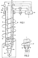
- a first auger 12 or inner auger which has a core 14 of diameter d 1 and whose lower end 14a is equipped with a tip 16 promoting the penetration of the auger into the ground and can play the role of discharge plug.
- This tip 16 which may have different configurations, has a maximum outside diameter at most equal to the diameter of the core 14.
- the core 14 is equipped with a blade 18 in the form of a helix which extends substantially over the entire length of the core 14 from its lower end 14a to near its upper end 14b.
- the outer diameter of the helical blade 18 of the auger 12 will be called d 2 .
- the upper end 14b of the core 14 cooperates with a first drill head 18 whose function is the rotation of the auger 14 by printing to it a speed of rotation and a torque defined by a control circuit 20.
- the other function of the drill head 18 is to apply to the auger 12 a force vertical penetration into the ground, controlled by the control circuit 22.
- the drilling head 18 is provided with a sensor 24 which makes it possible to determine the depth or speed of penetration of the end of the auger in the soil in the excavation of the lower end 14a of the inner auger 12.
- the apparatus also includes an external auger 26 which has a hollow core 28 and whose lower end 28a is opened.
- the upper end 28b of the core 28 cooperates with a second drilling head 30 independent of the first drilling head 18.
- the core 28 of the outer auger 26 is equipped on its outer face at least one helical blade 32 which extends from its end lower 28a to near its upper end 28b.
- the head of drilling 30 is associated with a control circuit of the speed of rotation and torque and referenced 34, to an application device of a force 36, and to a measuring sensor 40 of the depth of the end lower auger 26, in the excavation.
- the diameter d 1 of the core of the inner auger 12 and the diameter d 2 of the turn of the same auger are chosen in such a way that the ratio of the cross sectional area of the core to the surface a circle of diameter d 2 corresponding to the blade is between 25% and 80% and preferably between 30% and 50%.
- the ratio between the diameter d 3 of the core 28 of the external auger and the diameter d 4 of the helical blade 32 of the external auger 28 is chosen in such a way that the ratio between the surfaces of the circles of diameter d 3 and d 4 are between 25% and 60% and preferably between 30% and 50%.
- FIG. 2 shows an improved mode of embodiment in which the internal auger 12 is equipped with a dip tube 50 permitting, after completion of the excavation by drilling and / or discharge, convey the concrete or similar material necessary for realization of the molded pile inside the excavation carried out.
- a station or console 52 which allows to manage the control circuits 20 and 34 of the drill heads 18 and 30 according to instructions I entered in this station and according to information delivered by depth sensors 24 and 40.
- the instructions I entered in the control station 52 can advantageously resulting from test drilling carried out beforehand in the area where molded piles are to be made.
Landscapes
- Engineering & Computer Science (AREA)
- Structural Engineering (AREA)
- Life Sciences & Earth Sciences (AREA)
- General Life Sciences & Earth Sciences (AREA)
- Mining & Mineral Resources (AREA)
- Paleontology (AREA)
- Civil Engineering (AREA)
- General Engineering & Computer Science (AREA)
- Earth Drilling (AREA)
- Piles And Underground Anchors (AREA)
- Moulds For Moulding Plastics Or The Like (AREA)
Claims (7)
- Aushubvorrichtung für die Herstellung von geformten Pfählen, dadurch gekennzeichnet, daß sie umfaßt:so daß das Verhältnis Bohrung/Verdrängung variiert werden kann.einen ersten Erdlochbohrer (12), der eine erste Seele (14) mit einem Durchmesser d1, die in einer Spitze (16) endet, deren Außendurchmesser nicht über jenem der Seele (14) liegt, und mindestens eine Schaufel (18) in Propellerform umfaßt, welche sich im wesentlichen über die gesamte Länge der Seele (14) erstreckt, wobei der Außendurchmesser der Schaufel (18) gleich d2 ist;einen zweiten Erdlochbohrer (26), der eine zweite, hohle Seele (28) mit einem Innendurchmesser d3 > d2, in welcher der erste Erdlochbohrer (12) frei in Translation befestigt ist, und mindestens eine Schaufel (32) in Propellerform umfaßt, die sich im wesentlichen auf der gesamten Länge der zweiten Seele (28) erstreckt und einen Außendurchmesser d4 aufweist;einen ersten Bohrkopf (18), um den ersten Erdlochbohrer (12) zu drehen und eine vertikale Kraft auf den Erdlochbohrer (26) auszuüben;erste Mittel (20), um die Drehgeschwindigkeit, das Drehmoment und die vertikale Kraft zu steuern, die auf den ersten Erdlochbohrer (12) angewendet werden;erste Mittel (24), um die effektive Eindringgeschwindigkeit des ersten Erdlochbohrers (12) zu messen;einen zweiten Bohrkopf (30), der von dem ersten Kopf (18) unabhängig ist, und dem Drehen des zweiten Erdlochbohrers (26) und dem Anwenden einer vertikalen Kraft auf den Erdlochbohrer (26) dient;zweite Mittel (34) zum Steuern der Drehgeschwindigkeit, des Drehmoments und der vertikalen Kraft, die auf den zweiten Erdlochbohrer angewendet werden; undzweite Mittel (40) zum Messen der effektiven Eindringgeschwindigkeit des zweiten Erdlochbohrers,
- Vorrichtung nach Anspruch 1, dadurch gekennzeichnet, daß der Durchmesser d1 der Seele (14) des ersten Erdlochbohrers (12) so ist, daß 0,5 d2 < d1 < 0,75 d2.
- Vorrichtung nach einem der Ansprüche 1 bis 2, dadurch gekennzeichnet, daß der Durchmesser d3 der Seele des zweiten Erdlochbohrers (26) so ist, daß 0,5 d4 < d3 < 0,75 d4.
- Vorrichtung nach einem der Ansprüche 1 bis 3, dadurch gekennzeichnet, daß sie ferner eine Steueranordnung (52) umfaßt, um die Steuermittel der beiden Bohrköpfe getrennt zu steuern, damit jeder der beiden Erdlochbohrer getrennt im Verdrängungs- oder im Bohrungsmodus funktioniert oder angehalten wird.
- Vorrichtung nach Anspruch 4, dadurch gekennzeichnet, daß die Steueranordnung (52) Mittel zum gleichzeitigen Steuern der gleichzeitigen Drehung der beiden Erdlochbohrer (12, 26) umfaßt, so daß eine Bodenverdrängungsrate erreicht wird, welche dem Durchmesser der hohlen Seele des zweiten Erdlochbohrers entspricht.
- Vorrichtung nach Anspruch 5, dadurch gekennzeichnet, daß die Steueranordnung (52) Mittel zum Steuern der gleichzeitigen Drehung der beiden Erdlochbohrer (12, 26) umfaßt, um sie im Bohrungsmodus zu betreiben.
- Vorrichtung nach einem der Ansprüche 1 bis 6, dadurch gekennzeichnet, daß der erste Erdlochbohrer (12) mit einem Tauchrohr (50) ausgestattet ist, um während des Aushebens das Einführen von Material zu ermöglichen, das der Herstellung des Pfahls dient.
Applications Claiming Priority (2)
| Application Number | Priority Date | Filing Date | Title |
|---|---|---|---|
| FR0003103 | 2000-03-10 | ||
| FR0003103A FR2806110B1 (fr) | 2000-03-10 | 2000-03-10 | Appareil d'excavation pour la realisation de pieux moules |
Publications (2)
| Publication Number | Publication Date |
|---|---|
| EP1132525A1 EP1132525A1 (de) | 2001-09-12 |
| EP1132525B1 true EP1132525B1 (de) | 2005-12-14 |
Family
ID=8847961
Family Applications (1)
| Application Number | Title | Priority Date | Filing Date |
|---|---|---|---|
| EP01400576A Expired - Lifetime EP1132525B1 (de) | 2000-03-10 | 2001-03-06 | Aushubgerät für die Herstellung von Ortbetonpfählen |
Country Status (6)
| Country | Link |
|---|---|
| EP (1) | EP1132525B1 (de) |
| JP (1) | JP2001288974A (de) |
| AT (1) | ATE312977T1 (de) |
| DE (1) | DE60115741T2 (de) |
| FR (1) | FR2806110B1 (de) |
| HK (1) | HK1040538A1 (de) |
Families Citing this family (12)
| Publication number | Priority date | Publication date | Assignee | Title |
|---|---|---|---|---|
| FR2831205B1 (fr) * | 2001-10-24 | 2004-05-14 | Cie Du Sol | Procede et systeme de forage de puits pour la realisation de pieux moules |
| BE1018097A3 (nl) * | 2008-04-16 | 2010-05-04 | Noterman Putboringen | Boorvoorziening en werkwijze voor het vervaardigen van een funderingspaal en verbeterde funderingspaal met schroefvorm. |
| WO2011056162A2 (en) * | 2009-08-19 | 2011-05-12 | Leonardo Mohamed | A multifunctional screw drill and reaming device |
| WO2011048404A1 (en) * | 2009-10-23 | 2011-04-28 | Hesco Bastion Limited | Auger and method |
| GB2477792B (en) * | 2010-02-15 | 2012-02-15 | Hesco Bastion Ltd | Auger and method |
| GB2525630A (en) * | 2014-04-30 | 2015-11-04 | Roger Bullivant Ltd | Improvements in or relating to methods and apparatus for use in forming piles |
| CN106285461B (zh) * | 2016-11-01 | 2018-03-30 | 周兆弟 | 打桩机的钻杆转动驱动装置 |
| CN106978974B (zh) * | 2017-05-12 | 2024-04-09 | 李广信 | Cfg变径倒锥台阶型桩以及制备方法和钻具 |
| RO134509A1 (ro) | 2019-04-08 | 2020-10-30 | Tudor Saidel | Procedeu şi dispozitiv de execuţie pe loc a unui pilot, cu diametre diferite, descrescătoare în adâncime |
| CN111911075B (zh) * | 2020-09-15 | 2024-11-05 | 济宁市鲁星重工机械有限公司 | 一种多功能吊装旋挖钻一体机 |
| CN116291181B (zh) * | 2023-05-19 | 2023-08-08 | 山东能源重装集团大族再制造有限公司 | 一种适用于天然煤炭矿表层碎石土壤层的钻探设备 |
| US12282009B1 (en) * | 2024-04-30 | 2025-04-22 | Open Acre | System for measuring a ground material health level |
Family Cites Families (4)
| Publication number | Priority date | Publication date | Assignee | Title |
|---|---|---|---|---|
| GB1391109A (en) * | 1972-09-11 | 1975-04-16 | Turzillo L A | Method for producing pile or like structural columns in situ |
| DE3461663D1 (en) | 1983-07-07 | 1987-01-22 | Atlas Palen Nv | Method for casting piles by means of a drive-out screw |
| KR940004906B1 (ko) * | 1987-10-05 | 1994-06-04 | 가와사끼세이떼쓰 가부시끼가이샤 | 강관말뚝, 그의 제조방법 및 말뚝박는 방법 |
| ES2143356B1 (es) | 1997-01-10 | 2000-12-16 | Codina Juan Vicente Herrero | Dispositivo y procedimiento para la realizacion de pilotajes de cimentacion en maquinas perforadoras. |
-
2000
- 2000-03-10 FR FR0003103A patent/FR2806110B1/fr not_active Expired - Fee Related
-
2001
- 2001-03-06 EP EP01400576A patent/EP1132525B1/de not_active Expired - Lifetime
- 2001-03-06 DE DE60115741T patent/DE60115741T2/de not_active Expired - Fee Related
- 2001-03-06 AT AT01400576T patent/ATE312977T1/de not_active IP Right Cessation
- 2001-03-12 JP JP2001069363A patent/JP2001288974A/ja active Pending
-
2002
- 2002-03-07 HK HK02101754.2A patent/HK1040538A1/zh unknown
Also Published As
| Publication number | Publication date |
|---|---|
| DE60115741T2 (de) | 2006-09-07 |
| HK1040538A1 (zh) | 2002-06-14 |
| DE60115741D1 (de) | 2006-01-19 |
| JP2001288974A (ja) | 2001-10-19 |
| FR2806110B1 (fr) | 2002-12-27 |
| FR2806110A1 (fr) | 2001-09-14 |
| ATE312977T1 (de) | 2005-12-15 |
| EP1132525A1 (de) | 2001-09-12 |
Similar Documents
| Publication | Publication Date | Title |
|---|---|---|
| EP1132525B1 (de) | Aushubgerät für die Herstellung von Ortbetonpfählen | |
| EP1146173B1 (de) | Einrichtung zur Herstellung von Bohrpfählen | |
| EP3645823B1 (de) | Vertikales bohrsystem vom schneckentyp mit trajektoriekorrekturvorrichtung | |
| EP1306517A1 (de) | Verfahren und Vorrichtung zum Bohren bei der Herstellung von Betonpfählen | |
| EP2652205B1 (de) | Bohrverfahren | |
| EP1259792B1 (de) | Verfahren und vorrichtung zur einbringung eines rohrförmigem werkzeuges in den seeboden zwecks probenentnahme oder messung der eigenschaften dieses bodens, insbesondere in grosser tiefe | |
| EP1471186B1 (de) | Bohrschnecke zur Pfahlherstellung | |
| EP0382607B1 (de) | Vorrichtung zum Herstellen von Pfählen im Boden mit einem kontinuierlichen hohlen Bohrer | |
| EP2157277B1 (de) | Einrichtung zur Herstellung von Bohrungen im Boden | |
| FR2648839A1 (fr) | Pieux de fondation, procedes, outils et machines pour la construction desdits pieux | |
| EP0826835B1 (de) | Baggergerät zum Graben von Tiefgräben | |
| EP2631367B1 (de) | Bohrmaschine zum Aufstellen von Masten, die eine Sonde zur penetrometrischen Messung umfasst | |
| FR2889556A1 (fr) | Dispositif de forage d'un puits suivant un axe de forage pour mesurer un parametre d'une partie d'un sol | |
| EP3172383B1 (de) | Vorrichtung zur verankerung in mehrschichtigem boden mit verbindungsring | |
| EP3414399A1 (de) | Verfahren zur herstellung einer verankerungszugstange und verankerungszugstange | |
| FR2826050A1 (fr) | Outil de forage et de refoulement | |
| FR2797466A1 (fr) | Procede pour mesurer un parametre d'une partie d'un sol situee a une distance donnee de sa surface et dispositif permettant de mettre en oeuvre le procede | |
| FR2988423A1 (fr) | Appareil de nettoyage pour une tariere. | |
| EP2900875A1 (de) | Verfahren zur herstellung eines erdankers | |
| EP1085166A1 (de) | Spiralbohrer | |
| FR2635129A1 (fr) | Perfectionnements aux dispositifs et procedes pour la realisation de pieux en beton dans le sol | |
| FR2831206A1 (fr) | Outil de forage et de refoulement | |
| FR2889241A1 (fr) | Tariere a ergot mobile | |
| FR3024481A1 (fr) | Dispositif d'ancrage, structure amovible et procede d'ancrage associe | |
| FR2792341A1 (fr) | Dispositif de commande d'obturateur d'alimentation, equipement de forage tel que tariere, et element de fondation |
Legal Events
| Date | Code | Title | Description |
|---|---|---|---|
| PUAI | Public reference made under article 153(3) epc to a published international application that has entered the european phase |
Free format text: ORIGINAL CODE: 0009012 |
|
| AK | Designated contracting states |
Kind code of ref document: A1 Designated state(s): AT BE CH CY DE DK ES FI FR GB GR IE IT LI LU MC NL PT SE TR |
|
| AX | Request for extension of the european patent |
Free format text: AL;LT;LV;MK;RO;SI |
|
| 17P | Request for examination filed |
Effective date: 20011210 |
|
| AKX | Designation fees paid |
Free format text: AT BE CH CY DE DK ES FI FR GB GR IE IT LI LU MC NL PT SE TR |
|
| 17Q | First examination report despatched |
Effective date: 20031027 |
|
| GRAP | Despatch of communication of intention to grant a patent |
Free format text: ORIGINAL CODE: EPIDOSNIGR1 |
|
| GRAS | Grant fee paid |
Free format text: ORIGINAL CODE: EPIDOSNIGR3 |
|
| GRAA | (expected) grant |
Free format text: ORIGINAL CODE: 0009210 |
|
| AK | Designated contracting states |
Kind code of ref document: B1 Designated state(s): AT BE CH CY DE DK ES FI FR GB GR IE IT LI LU MC NL PT SE TR |
|
| PG25 | Lapsed in a contracting state [announced via postgrant information from national office to epo] |
Ref country code: IT Free format text: LAPSE BECAUSE OF FAILURE TO SUBMIT A TRANSLATION OF THE DESCRIPTION OR TO PAY THE FEE WITHIN THE PRESCRIBED TIME-LIMIT;WARNING: LAPSES OF ITALIAN PATENTS WITH EFFECTIVE DATE BEFORE 2007 MAY HAVE OCCURRED AT ANY TIME BEFORE 2007. THE CORRECT EFFECTIVE DATE MAY BE DIFFERENT FROM THE ONE RECORDED. Effective date: 20051214 Ref country code: IE Free format text: LAPSE BECAUSE OF FAILURE TO SUBMIT A TRANSLATION OF THE DESCRIPTION OR TO PAY THE FEE WITHIN THE PRESCRIBED TIME-LIMIT Effective date: 20051214 Ref country code: FI Free format text: LAPSE BECAUSE OF FAILURE TO SUBMIT A TRANSLATION OF THE DESCRIPTION OR TO PAY THE FEE WITHIN THE PRESCRIBED TIME-LIMIT Effective date: 20051214 Ref country code: GB Free format text: LAPSE BECAUSE OF FAILURE TO SUBMIT A TRANSLATION OF THE DESCRIPTION OR TO PAY THE FEE WITHIN THE PRESCRIBED TIME-LIMIT Effective date: 20051214 Ref country code: AT Free format text: LAPSE BECAUSE OF FAILURE TO SUBMIT A TRANSLATION OF THE DESCRIPTION OR TO PAY THE FEE WITHIN THE PRESCRIBED TIME-LIMIT Effective date: 20051214 Ref country code: NL Free format text: LAPSE BECAUSE OF FAILURE TO SUBMIT A TRANSLATION OF THE DESCRIPTION OR TO PAY THE FEE WITHIN THE PRESCRIBED TIME-LIMIT Effective date: 20051214 |
|
| REG | Reference to a national code |
Ref country code: GB Ref legal event code: FG4D Free format text: NOT ENGLISH |
|
| REG | Reference to a national code |
Ref country code: CH Ref legal event code: EP |
|
| REG | Reference to a national code |
Ref country code: IE Ref legal event code: FG4D Free format text: LANGUAGE OF EP DOCUMENT: FRENCH |
|
| REF | Corresponds to: |
Ref document number: 60115741 Country of ref document: DE Date of ref document: 20060119 Kind code of ref document: P |
|
| PG25 | Lapsed in a contracting state [announced via postgrant information from national office to epo] |
Ref country code: GR Free format text: LAPSE BECAUSE OF FAILURE TO SUBMIT A TRANSLATION OF THE DESCRIPTION OR TO PAY THE FEE WITHIN THE PRESCRIBED TIME-LIMIT Effective date: 20060314 Ref country code: DK Free format text: LAPSE BECAUSE OF FAILURE TO SUBMIT A TRANSLATION OF THE DESCRIPTION OR TO PAY THE FEE WITHIN THE PRESCRIBED TIME-LIMIT Effective date: 20060314 Ref country code: SE Free format text: LAPSE BECAUSE OF FAILURE TO SUBMIT A TRANSLATION OF THE DESCRIPTION OR TO PAY THE FEE WITHIN THE PRESCRIBED TIME-LIMIT Effective date: 20060314 |
|
| PG25 | Lapsed in a contracting state [announced via postgrant information from national office to epo] |
Ref country code: ES Free format text: LAPSE BECAUSE OF FAILURE TO SUBMIT A TRANSLATION OF THE DESCRIPTION OR TO PAY THE FEE WITHIN THE PRESCRIBED TIME-LIMIT Effective date: 20060325 |
|
| PG25 | Lapsed in a contracting state [announced via postgrant information from national office to epo] |
Ref country code: LI Free format text: LAPSE BECAUSE OF NON-PAYMENT OF DUE FEES Effective date: 20060331 Ref country code: CH Free format text: LAPSE BECAUSE OF NON-PAYMENT OF DUE FEES Effective date: 20060331 Ref country code: BE Free format text: LAPSE BECAUSE OF NON-PAYMENT OF DUE FEES Effective date: 20060331 Ref country code: MC Free format text: LAPSE BECAUSE OF NON-PAYMENT OF DUE FEES Effective date: 20060331 Ref country code: LU Free format text: LAPSE BECAUSE OF NON-PAYMENT OF DUE FEES Effective date: 20060331 |
|
| PG25 | Lapsed in a contracting state [announced via postgrant information from national office to epo] |
Ref country code: PT Free format text: LAPSE BECAUSE OF FAILURE TO SUBMIT A TRANSLATION OF THE DESCRIPTION OR TO PAY THE FEE WITHIN THE PRESCRIBED TIME-LIMIT Effective date: 20060515 |
|
| NLV1 | Nl: lapsed or annulled due to failure to fulfill the requirements of art. 29p and 29m of the patents act | ||
| GBV | Gb: ep patent (uk) treated as always having been void in accordance with gb section 77(7)/1977 [no translation filed] |
Effective date: 20051214 |
|
| REG | Reference to a national code |
Ref country code: IE Ref legal event code: FD4D |
|
| PG25 | Lapsed in a contracting state [announced via postgrant information from national office to epo] |
Ref country code: DE Free format text: LAPSE BECAUSE OF NON-PAYMENT OF DUE FEES Effective date: 20061003 |
|
| PLBE | No opposition filed within time limit |
Free format text: ORIGINAL CODE: 0009261 |
|
| STAA | Information on the status of an ep patent application or granted ep patent |
Free format text: STATUS: NO OPPOSITION FILED WITHIN TIME LIMIT |
|
| REG | Reference to a national code |
Ref country code: CH Ref legal event code: PL |
|
| 26N | No opposition filed |
Effective date: 20060915 |
|
| BERE | Be: lapsed |
Owner name: CIE DU SOL Effective date: 20060331 |
|
| PG25 | Lapsed in a contracting state [announced via postgrant information from national office to epo] |
Ref country code: TR Free format text: LAPSE BECAUSE OF FAILURE TO SUBMIT A TRANSLATION OF THE DESCRIPTION OR TO PAY THE FEE WITHIN THE PRESCRIBED TIME-LIMIT Effective date: 20051214 |
|
| REG | Reference to a national code |
Ref country code: HK Ref legal event code: WD Ref document number: 1040538 Country of ref document: HK |
|
| PG25 | Lapsed in a contracting state [announced via postgrant information from national office to epo] |
Ref country code: CY Free format text: LAPSE BECAUSE OF FAILURE TO SUBMIT A TRANSLATION OF THE DESCRIPTION OR TO PAY THE FEE WITHIN THE PRESCRIBED TIME-LIMIT Effective date: 20051214 |
|
| PGFP | Annual fee paid to national office [announced via postgrant information from national office to epo] |
Ref country code: FR Payment date: 20080327 Year of fee payment: 8 |
|
| REG | Reference to a national code |
Ref country code: FR Ref legal event code: ST Effective date: 20091130 |
|
| PG25 | Lapsed in a contracting state [announced via postgrant information from national office to epo] |
Ref country code: FR Free format text: LAPSE BECAUSE OF NON-PAYMENT OF DUE FEES Effective date: 20091123 |