EP1132316A1 - Container for dispensing beverages under air-free conditions - Google Patents
Container for dispensing beverages under air-free conditions Download PDFInfo
- Publication number
- EP1132316A1 EP1132316A1 EP00105575A EP00105575A EP1132316A1 EP 1132316 A1 EP1132316 A1 EP 1132316A1 EP 00105575 A EP00105575 A EP 00105575A EP 00105575 A EP00105575 A EP 00105575A EP 1132316 A1 EP1132316 A1 EP 1132316A1
- Authority
- EP
- European Patent Office
- Prior art keywords
- beverage container
- chamber section
- volume
- chamber
- beverage
- Prior art date
- Legal status (The legal status is an assumption and is not a legal conclusion. Google has not performed a legal analysis and makes no representation as to the accuracy of the status listed.)
- Granted
Links
Images


Classifications
-
- B—PERFORMING OPERATIONS; TRANSPORTING
- B65—CONVEYING; PACKING; STORING; HANDLING THIN OR FILAMENTARY MATERIAL
- B65D—CONTAINERS FOR STORAGE OR TRANSPORT OF ARTICLES OR MATERIALS, e.g. BAGS, BARRELS, BOTTLES, BOXES, CANS, CARTONS, CRATES, DRUMS, JARS, TANKS, HOPPERS, FORWARDING CONTAINERS; ACCESSORIES, CLOSURES, OR FITTINGS THEREFOR; PACKAGING ELEMENTS; PACKAGES
- B65D81/00—Containers, packaging elements, or packages, for contents presenting particular transport or storage problems, or adapted to be used for non-packaging purposes after removal of contents
- B65D81/24—Adaptations for preventing deterioration or decay of contents; Applications to the container or packaging material of food preservatives, fungicides, pesticides or animal repellants
- B65D81/245—Internal membrane, floating cover or the like isolating the contents from the ambient atmosphere
Definitions
- the invention relates to a beverage container Recording, storing and dispensing a drink in doses, that can be a ready mixed drink. Also from the Invention is concerned with an operating or working method Operate a beverage container to remove contaminants from the ready mixed and dispensed beverages avoid.
- Beverage containers usually consist of a lower and an upper chamber, the lower chamber the drink saves.
- the lower lying one that stores the drink Chamber section is assigned an outlet for metered Withdrawal of the stored drink.
- the second section of the chamber or the drink stored in it can be chilled.
- Premix dispensers can be found at locations or parking spaces Community catering, e.g. Canteens or restaurants in Companies, hospitals and old people's homes, but also in the System catering, such as fast food restaurants, kiosks or Snack bars, sports studios and in general in the hotel and Restaurant area.
- the object of the invention is therefore to improve the quality of the dispensed beverage, in particular not to reduce its quality by storing this beverage in the premix dispensing device over a longer period of time.
- the invention proposes the above To make the volume of the chamber section changeable. This provides a way to keep the drink under Keep air tight, both in the operating hours, as well outside of business hours. It is nevertheless achieved that at there is a change in volume when the beverage is dispensed, while maintaining the air seal, according to the Lowering the water level and without having to influence it the user.
- the upper volume and the lower volume are in a free flow connection (Claim 3) and can therefore easily counteract her Change volume without being in contact with ambient air come.
- a membrane (claim 4) protects against one Air access to the filled drink, which membrane on the one side is connected to the ambient air and on on the other hand delimits the first chamber, which in turn is one has free flow connection to the filled drink.
- the arrangement of the membrane can be rigid at the edges Cover part take place (claim 5).
- the arrangement can be in both half height, as well as in the upper or lower area of the lid respectively.
- At least a section of the membrane should be flexible and / or be elastic (claim 6).
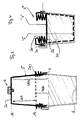
- a beverage dispenser is to be explained schematically with reference to FIG. 1 .
- the following elements are shown in section, a lower part 1 of a container and an upper part 2 placed on the lower part via a seal 3.
- Two filling heights h 1 and h 2 are shown in the lower part, each representative of a filling height of the filled drink G, which is represented here two alternatively specified outlets 8,8a can be removed. Either through the bottom wall of the lower container part 1 or through a lateral tap 8a.
- the upper part 2 which rests on the seal 3 so that Air exclusion is guaranteed is a schematic Lock 3a shown secured in the closed state.
- the upper part consists of a rigid lower wall section 2a and a rigid upper wall section 2b, which together form the Define the vertical extent of the upper part 2.
- the upper Wall section is with a horizontal section 2c closed, in which an opening 6a is provided, in the one Seal 6 is releasably used so that it is airtight Locking used and for supplying ambient air and be removed to create a free flow connection can.
- This element hereinafter referred to as the valve, allows the control of a membrane 4 explained below, which in Upper part 2 on the edge at a circumferential fastening point 4a is arranged airtight.
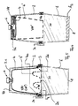
- FIGS. 2a, 2b and 1 correspond to three particularly recognizable in FIG. 2b Chamber areas. These chamber areas are the top one Chamber area 11, which leads to ambient air when valve 6 is open Has connection.
- the second, also arranged in the cover 2 Upper chamber area 10 ends at the upper end of the lower one Chamber area 20, which symbolizes the volume of the beverage. Volumes are assigned according to the chamber areas. For the top chamber area the volume V11, for the one in the lid still provided further upper chamber area 10 that Volume V10 and volume V20 for the drink.
- the changes in the different volumes go from one Comparison of Figures 2a and 2b.
- the two Volumes V10.V11 are assigned to the lid and the lower one Volume V20 the fuselage 1 of the entire container, the volumes should in their vertical order with first, second and third Volume.
- the first volume is in FIG. 2a practically zero
- the second volume V10 has its maximum value
- the third volume V20 corresponds to the filled one Beverage volume.
- the valve When the valve is open it lowers by reducing the Fill level ⁇ h from the membrane 4, by reducing the Membrane height ⁇ b.
- the volume V11 and changes accordingly becomes larger up to the maximum volume of FIG. 2b.
- the Volume V10 changes in opposite directions and decreases, corresponding to the increase in volume V11 if it is assumed that the filling volume V20 remains the same at Keeping a parting plane on the original Level hl. If you take a decrease in volume V20 according to the remaining beverage, so it stays Volume V10 unchanged, and the volumes V11 change and V20 in opposite directions.
- the first volume of the top Chamber section is therefore according to the metered delivery of Beverage changeable via the outlet. Alternatively, the Change the first or second volume V11, V10 dem Lowering of the water level in the second chamber section 20.
- the volume V11 acts as a pressure compensation volume, which for the complete emptying of the container is greater than or equal to that Volume V20 of the filled beverage is.
- the bilateral deflection of the membrane 4 based on one Horizontal plane along the peripheral edge attachment 4a half of the volume deflected in the upper end position Use membrane to double the volume available place, at least according to the filled Beverage volume.
- the lock 3a can be opened and the lid 2 is removed from the body 1.
- a new drink can be filled up to the filling level h 1 , and before the lid 2 is replaced, the membrane 4 is returned to its upper starting position and the valve 6 is initially closed. If the valve 6 is closed, with a practically negligible volume V11, the cover 2 can be handled freely without the risk that the membrane will fall out of its upper end position too soon. Only when the cover 2 is placed on the seals 3, in particular also when the latch 3a is closed, can the valve 6 be removed from the valve seat 6a, the membrane then still remaining in its practically unchanged upper end position. It now (first) follows the level of the metered beverage.
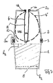
- FIG. 3 A not completely rigid design of the cover is shown in Figure 3 .
- the deformed locations of the cover are the walls here, with the upper end 2c of the cover, which is cup-shaped or square in the original, upper state, remaining essentially horizontal.
- the filling level of the beverage has decreased in accordance with the difference dimension ⁇ d, which is not shown separately in FIG. 3.
- the two volumes V10a and V10b are drawn in the upper and lower end positions of the horizontal section of the cover 2 * which can be deformed in the wall.
- the difference volume corresponds to the difference measure ⁇ d times the base area of the cover, at least essentially.
- the valve 6 shown is for the embodiment of FIG. 3 not absolutely necessary, but it can be used for repatriation of the lid from its elastically compressed state is helpful to avoid negative pressure. Throughout the entire Beverage dispensing valve 6 remains closed in order to Ambient air access to the first (upper) chamber V10 prevent and the surface of the drink before (new) preserve harmful influences.
- FIG. 3 An embodiment of an elastically deformable cover, which is designed in accordance with FIG. 3 but is reduced in container height, is illustrated in FIG .
- the horizontal section 2c of the lid which is elastically deformable in the wall regions 2w, lies essentially at the filling level of the beverage in the lower chamber section 20 before the dispensing begins. If the water level drops, the horizontal surface of the cover 2 * follows, elongating the wall sections 2w.
- These can either be elastic, or they can be meandering or accordion-like in order to allow them to yield and practically correspond to the inner shape of the second chamber 20 at the end of the removal process.
- the elastic shaping is inverted compared to FIG. 3, the lid is not compressed, but decompressed, based on the deformable section. Also in FIG. 4, a valve is not absolutely necessary, but may be helpful for returning the cover 2 * to its initial position.
- Figure 5 illustrates a bag-shaped membrane 4, which is shown both in the upper starting position, when the drink is full in the chamber volume 20, and - in dashed lines - in the lower end position 4 'when the drink is dispensed and the pressure compensation in the lower chamber volume by giving in of the bag in the direction of the water level.
- an arrangement of the edge 4a of the bag 4 at the lower edge, near the seal 3, is provided.
- the volume of the bag is therefore twice as large, based on the level at the height of the seal.
- the valve which is also shown, is used - as in FIG. 2b - to return the bag from its lower end position to its upper starting position.
- the valve is only opened before the start of beverage dispensing and allows new ambient air to be fed into the uppermost chamber volume V11.
- the valve helps to temporarily fix the larger bag 4 in the upper starting position until it is placed on the seal.
- the lid can be a pot or hood-shaped top have an additional plate-shaped connecting part that is arranged at the height of the seal 3 and in Flow connection with the lower chamber volume 20 is.
- the horizontal connecting plate 2d can be used together with the Seal 3 and the lid upper part 2a, 2b as a common Attachment part to be formed.
- the lid is there to compensate for the compressed air to create, he does not take a drink himself, but is in the Volume adapted to the chamber volume of the beverage.
- FIG. 6 illustrates a further design of the rigid lid part 2, with the fuselage 1 unchanged.
- a similarly flexibly designed bag 4 is shown in the upper rest position and in the lower deflected position 4 ′, the lower position being dashed.
- the deflected position 4 ' includes the filling height h 2 of the beverage dispensed through the outlet 8 in the second chamber volume 20.
- the edge fastening 4a of the bag-shaped container 4 is again circumferential, but here it is provided at the upper end of the rigid lid 2, essentially opposite to the previous location of FIG. 5, where the membrane is formed near the seal 3 on the cover 2 or directly on the seal 3 or even in one piece with the seal 3.
- the volumes are uncoated when filled (V11) and in emptied condition deleted (V11 ') clarified.
- the valve 6 is to be opened when removing the drink, so that the originally small volume V11 to a larger volume V11 ' can develop, with a corresponding reduction of initially larger volume V10, with an assumed constant Volume V20. If the volume V20 is as appropriate Increasing the volume V11 assuming a reduction, so remains the intermediate volume V10 constant.
- the membrane 4 can be flexible with itself overlapping sections in the compressed state as well be formed as elastic without such overlapping Sections.
- FIGS. 5 and 6 Both realizations of FIGS. 5 and 6 can be modified such that the bag lies at the height of the beverage surface before the start of the beverage dispensing and closely follows it during the dispensed dispensing.
- an elongation prepared by folding is possible as well as an enlargement made possible by elasticity.
- the intermediate wall 2d of the cover 2 would be omitted to enable the membrane 4 to be adjusted, the volume V10 being very small, whereas the volume V11 would increase as the filling height h 1 decreased. There would then be no need to design the cover 2 hood-shaped. It could have a reduced overall height.
- FIG. 7 A balloon-like design of the membrane 4 is illustrated in FIG. 7 .
- the elastic bag arranged in the upper horizontal section 2c fills up in volume, the upper chamber 11 being an inner chamber with an initial volume Vlla and a final volume Vllb.
- the volume V10 of the further upper chamber 10 what has been said above applies, either this volume decreases with a constant volume V20, or it remains the same if the volume V20 also changes in accordance with the decrease in the filling height h 1 .
- the balloon-like design of the membrane 4 can be prepared by elasticity as well as by elongation or volume expansion made possible by folds.
- a balloon with reduced volume is shown in the starting position 4 in such a way that its edge section 4b is arranged on an opening 6a of a horizontal section 2c of the cover.
- the valve is open and a drop in the water level h 1 allows the volume Vlla to expand to the volume Vllb in the state 4 ′ of the membrane 4 shown in broken lines.
- the arrangement 4b as an inlet area can also be off-center respectively.
- the cover 2 is inflexible.
Abstract
Description
Die Erfindung befaßt sich mit einem Getränkebehälter zur Aufnahme, Speicherung und zur dosierten Abgabe eines Getränks, das ein fertig gemischtes Getränk sein kann. Ebenfalls von der Erfindung betroffen ist ein Betriebs- oder Arbeitsverfahren zum Betreiben eines Getränkebehälters, um Verunreinigungen des fertig gemischten und dosiert abgegebenen Getränkes zu vermeiden.The invention relates to a beverage container Recording, storing and dispensing a drink in doses, that can be a ready mixed drink. Also from the Invention is concerned with an operating or working method Operate a beverage container to remove contaminants from the ready mixed and dispensed beverages avoid.
Getränkebehälter bestehen in der Regel aus einer unteren und einer oberen Kammer, wobei die untere Kammer das Getränk speichert. Dem das Getränk speichernden, tiefer liegenden Kammerabschnitt ist ein Auslaß zugeordnet, zur dosierten Entnahme des gespeicherten Getränks. Der zweite Kammerabschnitt oder das in ihm gespeicherte Getränk können gekühlt sein. Solche Premix-Dispenser finden sich an Standorten bzw. Stellplätzen zur Gemeinschaftsverpflegung, z.B. Kantinen oder Restaurants in Betrieben, Krankenhäusern und Altenheimen, aber auch in der Systemgastronomie, wie Fast-Food-Restaurants, Kiosken oder Imbißbetrieben, Sport-Studios sowie allgemein im Hotel- und Gaststättenbereich.Beverage containers usually consist of a lower and an upper chamber, the lower chamber the drink saves. The lower lying one that stores the drink Chamber section is assigned an outlet for metered Withdrawal of the stored drink. The second section of the chamber or the drink stored in it can be chilled. Such Premix dispensers can be found at locations or parking spaces Community catering, e.g. Canteens or restaurants in Companies, hospitals and old people's homes, but also in the System catering, such as fast food restaurants, kiosks or Snack bars, sports studios and in general in the hotel and Restaurant area.
Um das Getränk jeweils nachfüllen zu können, existiert ein zumeist lose auf dem oberen Kammerabschnitt aufliegender Behälterdeckel, der nicht vermeiden kann, das das Getränk in ständigem Kontakt mit der Umgebungsluft steht, die an einigen Standorten durchaus belastet sein kann, aber auch die Gefahr mit sich bringt, fahrlässigen oder vorsätzlichen Verunreinigungen des Getränks, insbesondere in den Zeiträumen, welche außerhalb der Betriebszeiten und damit der zugehörigen Überwachungen liegen, eine Basis zu bieten. Geht man den Weg, die Behälterdeckel abzudichten und absichtlich luftundurchlässig zu machen, fehlt ein Erfordernis bei der Getränkeabgabe, namentlich der erforderliche Druckausgleich beim langsamen und dosierten Abgeben des Getränks. Selbst ein nur teilweise abdichtender Deckel, der in den Betriebszeiten geöffnet wird und außerhalb der Betriebszeiten luftdicht verschlossen ist, kann die Gefahr der Verunreinigung durch ständigen Kontakt mit erneuerter Umgebungsluft - zumindest während der Betriebszeiten - nicht verhindern.In order to refill the drink, there is a mostly lying loosely on the upper chamber section Container lid that can not avoid that the drink in is in constant contact with the ambient air, which some Locations can be burdened, but also with the danger brings negligent or willful contamination of the drink, especially in the periods outside the operating times and thus the associated monitoring to provide a basis. If you go the way that Sealing the container lid and intentionally closing it to air make, there is no requirement for beverage delivery, namely the necessary pressure compensation for slow and dosed Deliver the drink. Even a partially sealing one Lid that is opened during operating hours and outside of the operating times is sealed airtight, the danger contamination through constant contact with renewed Ambient air - at least during the operating hours - not prevent.
Die Erfindung hat sich deshalb zur Aufgabe gestellt, die Qualität des dosiert abgegebenen Getränks zu verbessern, insbesondere seine Qualität nicht dadurch herabzusetzen, daß dieses Getränk ggf. über einen längeren Zeitraum in dem Premix-Ausschankgerät gespeichert bleibt.The object of the invention is therefore to improve the quality of the dispensed beverage, in particular not to reduce its quality by storing this beverage in the premix dispensing device over a longer period of time.
Zur Lösung dieser Aufgabe schlägt die Erfindung vor, den oberen Kammerabschnitt in seinem Volumen veränderbar zu gestalten. Damit ist eine Möglichkeit gegeben, das Getränk dauernd unter Luftabschluß zu halten, sowohl in den Betriebszeiten, wie auch außerhalb der Betriebszeiten. Es wird dennoch erreicht, daß bei der Abgabe des Getränkes eine Volumenveränderung stattfindet, unter Beibehaltung des Luftabschlusses, entsprechend dem Absinken des Pegelstandes und ohne notwendige Einflußnahme durch den Benutzer.To achieve this object, the invention proposes the above To make the volume of the chamber section changeable. This provides a way to keep the drink under Keep air tight, both in the operating hours, as well outside of business hours. It is nevertheless achieved that at there is a change in volume when the beverage is dispensed, while maintaining the air seal, according to the Lowering the water level and without having to influence it the user.
Die Veränderung des Volumens geschieht quasi von selbst, allein durch das Absinken des Pegelstandes.The change in volume happens almost automatically, alone by the drop in the water level.
Es versteht sich, daß die Veränderbarkeit in verschiedenen Arten
realisiert werden kann. Ausgehend davon, daß sich das Volumen
der oberen Kammer gegenläufig zur Abnahme des tiefer liegenden
Getränkevolumens bei der dosierten Abgabe entwickelt, kann ein
weiteres oberes Volumen hinzutreten, das gemäß Anspruch 2
gegenläufig zur Abnahme des ersten oberen Volumens arbeitet und
mit der Umgebungsluft in Verbindung steht (Anspruch 2).It is understood that the changeability in different ways
can be realized. Assuming that the volume
the upper chamber counter to the decrease of the lower one
Beverage volume developed during metered dispensing can
add further upper volume, which according to
Das obere Volumen und das untere Volumen (letzteres mit dem eingefüllten Getränk) stehen in einer freien Strömungsverbindung (Anspruch 3) und können deshalb ohne weiteres gegenläufig ihr Volumen verändern, ohne mit Umgebungsluft in Verbindung zu kommen. Statt dessen schützt eine Membran (Anspruch 4) vor einem Luftzutritt zu dem eingefüllten Getränk, welche Membran auf der einen Seite mit der Umgebungsluft in Verbindung steht und auf der anderen Seite die erste Kammer begrenzt, die ihrerseits eine freie Strömungsverbindung zum eingefüllten Getränk besitzt.The upper volume and the lower volume (the latter with the filled drink) are in a free flow connection (Claim 3) and can therefore easily counteract her Change volume without being in contact with ambient air come. Instead, a membrane (claim 4) protects against one Air access to the filled drink, which membrane on the one side is connected to the ambient air and on on the other hand delimits the first chamber, which in turn is one has free flow connection to the filled drink.
Die Anordnung der Membran kann randseitig in einem starren Deckelteil erfolgen (Anspruch 5). Die Anordnung kann sowohl in halber Höhe, wie auch im oberen oder unteren Bereich des Deckels erfolgen. Zumindest ein Abschnitt der Membran sollte flexibel und/oder elastisch ausgebildet sein (Anspruch 6).The arrangement of the membrane can be rigid at the edges Cover part take place (claim 5). The arrangement can be in both half height, as well as in the upper or lower area of the lid respectively. At least a section of the membrane should be flexible and / or be elastic (claim 6).
Zur Veränderung des ersten (oberen) Kammervolumens kann auch
eine Veränderung des Deckelteils selbst vorgesehen werden, indem
es luftdicht gegenüber der Außenluft abgeschlossen ist und mit
Absinken des Pegelstandes seine Form (sein Volumen) verändert.
Der an dem Deckel angreifende Unterdruck sorgt für ein Nachgeben
des Deckels und für eine Reduzierung des oberen Volumens,
entsprechend dem Absinken des Pegelstandes des eingefüllten
Getränks (Anspruch 7a). Für eine solche Verformung bietet sich
ein elastisch verformbarer Deckel an, der insbesondere in seinen
Seitenwandabschnitten eine Nachgiebigkeit aufweist. Ist dagegen
eine flexible, elastische oder nachgiebige Membran vorgesehen,
so kann der Deckel als solches starr sein (Anspruch 10,14). You can also change the first (upper) chamber volume
a change of the lid part itself can be provided by
it is airtight and sealed off from the outside air
Falling level changes its shape (volume).
The negative pressure applied to the lid ensures that it gives way
of the lid and for a reduction in the upper volume,
corresponding to the drop in the level of the filled
Beverage (claim 7a). For such a deformation offers
an elastically deformable lid, which in particular in its
Sidewall sections has a compliance. Is against
a flexible, elastic or resilient membrane is provided,
the lid as such can be rigid (
Auführungsbeispiele der Erfindung sind in den Zeichnungen erläutert.
-
Figur 1 - ist ein erstes Ausführungsbeispiel des
Getränkebehälters mit zwei Lagen einer
verformbaren Membran 4, die den vollständig befüllten Behälter (Strichlinie) oder den entleerten Behälter (durchgezogen) veranschaulicht. -
Figur 2a Figur 2b - veranschaulichen die beiden in
Figur 1 zusammen eingezeichneten Zustände jeweils individuell, verbunden mit dem jeweils zugehörigen Pegelstand h1 bzw. h2. -
Figur 3 - veranschaulicht ein elastisches Deckelteil, ohne eine zusätzliche Membran.
-
Figur 4 - veranschaulicht eine alternative Deckelgestaltung mit ebenfalls elastisch nachgiebigen Abschnitten.
-
Figur 5Figur 6 Figur 7 - veranschaulichen alternative Ausführungsformen mit starrem Deckel und einer zusätzlich darin angeordneten Membran, die entweder flexibel, elastisch oder nachgiebig gestaltet ist.
- Figure 1
- is a first embodiment of the beverage container with two layers of a
deformable membrane 4, which illustrates the completely filled container (dashed line) or the empty container (solid). - Figure 2a Figure 2b
- 1 illustrate the two states drawn together in FIG. 1 individually, connected to the respectively associated level h 1 and h 2 .
- Figure 3
- illustrates an elastic cover part, without an additional membrane.
- Figure 4
- illustrates an alternative lid design with also resilient sections.
- Figure 5 Figure 6 Figure 7
- illustrate alternative embodiments with a rigid lid and an additional membrane arranged therein, which is either flexible, elastic or flexible.
Anhand von Figur 1 soll ein Getränke-Ausschankgerät schematisch
erläutert werden. Im Schnitt sind folgende Elemente gezeigt, ein
Unterteil 1 eines Behälters und ein auf das Unterteil über eine
Dichtung 3 aufgesetztes Oberteil 2. Im Unterteil sind zwei
Füllhohen h1 und h2 eingezeichnet, jeweils repräsentativ für eine
Füllhöhe des eingefüllten Getränkes G, das hier durch zwei
alternativ angegebene Auslässe 8,8a entnommen werden kann.
Entweder durch die Bodenwand des Behälterunterteils 1 oder durch
einen seitlichen Zapfhahn 8a. A beverage dispenser is to be explained schematically with reference to FIG. 1 . The following elements are shown in section, a
Das Oberteil 2, das auf der Dichtung 3 so aufsitzt, daß
Luftabschluß gewährleistet ist, ist über eine schematisch
dargestellte Verriegelung 3a im geschlossenen Zustand gesichert.
Das Oberteil besteht aus einem starren unteren Wandabschnitt 2a
und einem starren oberen Wandabschnitt 2b, die zusammen die
Vertikalerstreckung des Oberteils 2 definieren. Der obere
Wandabschnitt ist mit einem horizontalen Abschnitt 2c
verschlossen, in dem eine Öffnung 6a vorgesehen ist, in die eine
Dichtung 6 lösbar so eingesetzt ist, daß sie zum luftdichten
Abschließen eingesetzt und zum Zuführen von Umgebungsluft und
zum Schaffen einer freien Strömungsverbindung entnommen werden
kann. Dieses im folgenden als Ventil bezeichnete Element erlaubt
die Steuerung einer weiter unten erläuterten Membran 4, die im
Oberteil 2 randseitig an einer umlaufenden Befestigungsstelle 4a
luftdicht angeordnet ist.The
Die einzelnen Volumina der unterschiedlichen Kammern oder
Abteilungen sollen erläutert werden, wenn die Funktion der
Membran beschrieben wurde, die auch anhand der Figuren 2a und 2b
gezeigt werden kann, die dieselben Elemente zeigt wie die
Figur 1.
Die in den Figuren 2a,2b sowie 1 eingezeichneten Volumina
entsprechen drei besonders in Figur 2b zu erkennenden
Kammerbereichen. Diese Kammerbereiche sind der oberste
Kammerbereich 11, der zur Umgebungsluft bei geöffnetem Ventil 6
Verbindung hat. Der ebenfalls im Deckel 2 angeordnete zweite
obere Kammerbereich 10 endet am oberen Ende des unteren
Kammerbereiches 20, der das Volumen des Getränkes symbolisiert.
Entsprechend den Kammerbereichen sind Volumina zugeordnet. Für
den obersten Kammerbereich das Volumen V11, für den im Deckel
noch vorgesehenen weiteren oberen Kammerbereich 10 das
Volumen V10 und für das Getränk das Volumen V20.The volumes shown in FIGS. 2a, 2b and 1
correspond to three particularly recognizable in FIG. 2b
Chamber areas. These chamber areas are the top one
Die Veränderungen der unterschiedlichen Volumen gehen aus einem
Vergleich der Figuren 2a und 2b hervor. Obwohl die beiden
Volumina V10.V11 dem Deckel zugeordnet sind und das untere
Volumen V20 dem Rumpf 1 des Gesamtbehälters, sollen die Volumina
in ihrer vertikalen Reihenfolge mit erstes, zweites und dritten
Volumen bezeichnet werden. Das erste Volumen ist in der Figur 2a
praktisch Null, das zweite Volumen V10 hat seinen Maximalwert
und das dritte Volumen V20 entspricht dem eingefüllten
Getränkevolumen.The changes in the different volumes go from one
Comparison of Figures 2a and 2b. Although the two
Volumes V10.V11 are assigned to the lid and the lower one
Volume V20 the
Bei geöffnetem Ventil senkt sich durch Reduzierung der
Füllhöhe Δh die Membran 4 ab, durch Reduzierung der
Membranhöhe Δb. Entsprechend verändert sich das Volumen V11 und
wird größer, bis zu dem Maximalvolumen der Figur 2b. Das
Volumen V10 verändert sich gegenläufig und reduziert sich,
entsprechend der Zunahme des Volumens V11, wenn angenommen wird,
daß das Einfüllvolumen V20 weiterhin gleich bleibt, bei
Beibehaltung einer Trennebene auf der ursprünglichen
Füllhöhe hl. Nimmt man ein Absinken des Volumens V20
entsprechend dem verbleibenden Getränkerest an, so bleibt das
Volumen V10 unverändert, und es verändern sich die Volumina V11
und V20 gegenläufig. Das erste Volumen des oberen
Kammerabschnitts ist also entsprechend der dosierten Abgabe des
Getränks über den Auslaß veränderbar. Alternativ entspricht die
Veränderung des ersten oder zweiten Volumens V11,V10 dem
Absinken des Pegelstandes im zweiten Kammerabschnitt 20.When the valve is open it lowers by reducing the
Fill level Δh from the
Das Volumen V11 wirkt als Druckausgleichs-Volumen, welches für
die vollständige Entleerung des Behälters größer oder gleich dem
Volumen V20 des eingefüllten Getränkes ist. Gemäß Figur 2b kann
die bilaterale Auslenkung der Membran 4, orientiert an einer
Horizontalebene entlang der umlaufenden Randanbringung 4a, ein
hälftiges Volumen einer in der oberen Endlage ausgelenkte
Membran dazu verwenden, das doppelte Volumen zur Verfügung zu
stellen, entsprechend zumindest dem eingefüllten
Getränkevolumen.The volume V11 acts as a pressure compensation volume, which for
the complete emptying of the container is greater than or equal to that
Volume V20 of the filled beverage is. According to Figure 2b
the bilateral deflection of the
Ist das Getränk entnommen und die Membran 4 in der unteren
Endposition gemäß Figur 2b, kann die Arretierung 3a geöffnet
werden und der Deckel 2 wird von dem Rumpf 1 abgenommen. Ein
neues Getränk kann bis zur Füllhöhe h1 eingefüllt werden, und
bevor der Deckel 2 erneut aufgesetzt wird, wird die Membran 4 in
ihre obere Ausgangslage zurückversetzt und das Ventil 6 zunächst
geschlossen. Ist das Ventil 6 geschlossen, bei praktisch
vernachlässigbaren Volumen V11, kann der Deckel 2 frei
gehandhabt werden, ohne die Gefahr, daß die Membran zu früh aus
ihrer oberen Endlage herausfällt. Erst dann, wenn der Deckel 2
auf die Dichtungen 3 aufgesetzt ist, insbesondere auch dann,
wenn die Verriegelung 3a geschlossen ist, kann das Ventil 6 aus
dem Ventilsitz 6a herausgenommen werden, wobei die Membran dann
noch immer in ihrer praktisch unveränderten oberen Endlage
verbleibt. Sie folgt jetzt (erst) dem Pegelstand des dosiert
entnommenen Getränkes.Once the drink has been removed and the
Alternative Ausführungsformen des anhand der Figuren 1,2a,2b beschriebenen Konzeptes finden sich in den folgenden Figuren.Alternative embodiments of the based on Figures 1,2a, 2b The concept described can be found in the following figures.
Eine nicht vollständig starre Ausbildung des Deckels ist in
Figur 3 dargestellt. Der dortige Deckel 2* gibt unter
entstehendem Unterdruck im Wandabschnitt 2w nach, und die beiden
Kammerabschnitte, der obere Kammerabschnitt und der untere
Kammerabschnitt bilden eine gemeinsame Kammer. Die verformten
Stellen des Deckels sind hier die Wände, bei im wesentlichen
horizontal verbleibendem oberen Ende 2c des im oberen
ursprünglichen Zustand d1 topfförmigen oder quadratischen
Deckels. Im abgesenkten, mit elastisch verformten Wänden
versehenen Zustand bei der Höhe d2 ist der Füllpegel des
Getränkes entsprechend dem Differenzmaß Δd gesunken, was in
Figur 3 nicht gesondert eingezeichnet ist. Eingezeichnet sind
die beiden Volumina V10a und V10b in der oberen und unteren
Endlage des horizontalen Abschnitts des in der Wand verformbaren
Deckels 2*. Das Differenzvolumen entspricht dem Differenzmaß Δd
mal der Grundfläche des Deckels, zumindest im wesentlichen.A not completely rigid design of the cover is shown in Figure 3 . The
Das eingezeichnete Ventil 6 ist für die Ausführung der Figur 3
nicht zwingend erforderlich, es kann aber bei der Rückführung
des Deckels aus seinem elastisch komprimierten Zustand hilfreich
sein, um Unterdruck zu vermeiden. Während der gesamten
Getränkeabgabe bleibt das Ventil 6 aber geschlossen, um der
Umgebungsluft den Zutritt zu der ersten (oberen) Kammer V10 zu
verwehren und die Oberfläche des Getränkes vor (neuen)
schädlichen Einflüssen zu bewahren. The
Soweit andere Konstruktionselemente des Dispensers von Figur 3 nicht gesondert erläutert worden sind, sind sie identisch mit denjenigen der Figuren 2.As far as other construction elements of the dispenser of Figure 3 have not been explained separately, they are identical to those of Figures 2.
Eine entsprechend der Figur 3 ausgestaltete, aber in der
Behälterhöhe reduzierte Ausführung eines elastisch verformbaren
Deckels ist in Figur 4 veranschaulicht. Der horizontale
Abschnitt 2c des in den Wandbereichen 2w elastisch verformbaren
Deckels liegt vor Beginn der Ausgabe im wesentlichen auf der
Füllhöhe des Getränks im unteren Kammerabschnitt 20 auf. Sinkt
der Pegelstand, folgt die horizontale Fläche des Deckels 2*
nach, unter Längung der Wandabschnitte 2w. Diese können entweder
elastisch ausgebildet sein, oder aber mäander- oder
ziehharmonikaartig, um ein Nachgeben zu erlauben und am Ende des
Entnahmevorgangs praktisch der inneren Form der zweiten
Kammer 20 zu entsprechen. Die elastische Ausformung geschieht
gegenüber der Figur 3 invertiert, es wird der Deckel nicht
komprimiert, sondern entkomprimiert, bezogen auf den
verformbaren Abschnitt. Auch in Figur 4 ist ein Ventil nicht
zwingend erforderlich, möglicherweise aber hilfreich zur
Rückführung des Deckels 2* in seine Ausgangslage.An embodiment of an elastically deformable cover, which is designed in accordance with FIG. 3 but is reduced in container height, is illustrated in FIG . The
Figur 5 veranschaulicht eine beutelförmig ausgebildete
Membran 4, die sowohl in der oberen Ausgangslage, bei gefülltem
Getränk im Kammervolumen 20, wie auch - strichliniert - in der
unteren Endlage 4' dargestellt ist, wenn das Getränk abgegeben
ist und der Druckausgleich im unteren Kammervolumen durch
Nachgeben des Beutels in Richtung auf den Pegelstand erfolgt
ist. Gegenüber der Figur 2b ist eine Anordnung des Randes 4a des
Beutels 4 am unteren Rand, nahe der Dichtung 3 vorgesehen. Das
Volumen des Beutels ist demnach doppelt so groß, bezogen auf die
Ebene in der Höhe der Dichtung. Das ebenfalls eingezeichnete
Ventil dient - wie schon bei Figur 2b - zum Rückführen des
Beutels aus seiner unteren Endlage in seine obere Ausgangslage.
Das Ventil wird erst geöffnet, vor Beginn der Getränkeausgabe
und erlaubt die Zufuhr neuer Umgebungsluft in das oberste
Kammervolumen V11. Auch hier hilft das Ventil bei der temporären
Fixierung des größeren Beutels 4 in der oberen Ausgangslage, bis
zum Aufsetzen auf die Dichtung. Figure 5 illustrates a bag-shaped
Der Deckel kann außer einem topf- oder haubenförmigen Oberteil
ein zusätzliches plattenförmiges Verbindungsteil besitzen, das
in der Höhe der Dichtung 3 angeordnet ist und in
Strömungsverbindung mit dem unteren Kammervolumen 20 steht. Die
horizontale Verbindungsplatte 2d kann gemeinsam mit der
Dichtung 3 und dem Deckeloberteil 2a,2b als ein gemeinsames
Aufsetzteil ausgebildet sein.The lid can be a pot or hood-shaped top
have an additional plate-shaped connecting part that
is arranged at the height of the
Ebenso wie bei allen vorhergehenden und nachfolgenden Ausführungsformen ist der Deckel dazu da, den Druckluftausgleich zu schaffen, er nimmt selbst kein Getränk auf, ist aber im Volumen an das Kammervolumen des Getränkes angepaßt.As with all previous and subsequent ones In embodiments, the lid is there to compensate for the compressed air to create, he does not take a drink himself, but is in the Volume adapted to the chamber volume of the beverage.
Figur 6 veranschaulicht eine weitere Gestaltung des starren
Deckelteils 2, bei unverändertem Rumpf 1. Ein in ähnlicher Weise
flexibel gestalteter Beutel 4 ist in oberer Ruhestellung und in
unterer ausgelenkter Stellung 4' gezeigt, wobei die untere
Stellung strichliniert ist. Zu der ausgelenkten Stellung 4'
gehört die Füllhöhe h2 des durch den Auslaß 8 dosiert abgegebenen
Getränks in dem zweiten Kammervolumen 20. Die Randbefestigung 4a
des beutelförmigen Behälters 4 ist zwar erneut umlaufend, hier
aber am oberen Ende des starren Deckels 2 vorgesehen, im
wesentlichen entgegengesetzt zu dem vorhergehenden
Anbringungsort der Figur 5, wo die Membran nahe der Dichtung 3
am Deckel 2 bzw. direkt an der Dichtung 3 oder sogar einstückig
mit der Dichtung 3 ausgebildet ist. FIG. 6 illustrates a further design of the
Die Volumina sind im gefüllten Zustand ungestrichen (V11) und im
entleerten Zustand gestrichen (V11') verdeutlicht. Das Ventil 6
ist bei der Entnahme des Getränks zu öffnen, so daß sich das
ursprünglich kleine Volumen V11 zu einem größeren Volumen V11'
entwickeln kann, bei entsprechender Reduzierung des zunächst
größeren Volumens V10, bei einem angenommenen gleichbleibenden
Volumen V20. Wird das Volumen V20 als sich entsprechend dem
Vergrößern des Volumens V11 reduzierend angenommen, so bleibt
das Zwischenvolumen V10 konstant. Das Zurückführen des Beutels 4
von Figur 6 nach der Entnahme und das Halten dieses Beutels in
der komprimierten Position am oberen Deckelende 2c geschieht
durch Schließen des Ventils 6 und im übrigen ebenso, wie zu den
Figuren 2 erläutert. Die Membran 4 kann flexibel mit sich
überlappenden Abschnitten im komprimierten Zustand ebenso
ausgebildet werden, wie elastisch ohne solche überlappende
Abschnitte.The volumes are uncoated when filled (V11) and in
emptied condition deleted (V11 ') clarified. The
Beide Realisierungen der Figuren 5 und 6 können so modifiziert
werden, daß vor Beginn der Getränkeausgabe der Beutel in der
Höhe der Getränkeoberfläche liegt und ihr bei der dosierten
Abgabe eng benachbart folgt. Auch hier ist eine durch Faltung
vorbereitete Längung ebenso möglich wie eine durch Elastizität
ermöglichte Vergrößerung. In Figur 5 würde dazu die
Zwischenwand 2d des Deckels 2 fortfallen, um ein Nachführen der
Membran 4 zu ermöglichen, wobei das Volumen V10 sehr klein wäre,
dagegen das Volumen V11 sich mit senkender Füllhöhe h1 vergrößern
würde. Es würde dann die Notwendigkeit entfallen, den Deckel 2
haubenförmig auszugestalten. Er könnte eine reduzierte Bauhöhe
aufweisen.Both realizations of FIGS. 5 and 6 can be modified such that the bag lies at the height of the beverage surface before the start of the beverage dispensing and closely follows it during the dispensed dispensing. Here, too, an elongation prepared by folding is possible as well as an enlargement made possible by elasticity. In FIG. 5, the
Eine ballonartige Gestaltung der Membran 4 ist in Figur 7
veranschaulicht. Während der Getränkeausgabe füllt sich der im
oberen Horizontalabschnitt 2c angeordnete elastische Beutel in
seinem Volumen an, wobei die obere Kammer 11 eine innere Kammer
mit einem Anfangsvolumen Vlla und einem Endvolumen Vllb ist.
Hinsichtlich des Volumens V10 der weiteren oberen Kammer 10 gilt
das zuvor Gesagte, entweder sinkt dieses Volumen bei konstantem
Volumen V20, oder aber es bleibt gleich, wenn sich das
Volumen V20 entsprechend dem Absinken der Füllhöhe h1 mit ändert.A balloon-like design of the
Die ballonartige Gestaltung der Membran 4 kann durch Elastizität
wie auch durch von Falten ermöglichter Längung oder
Volumenerweiterung vorbereitet sein. Ein in seinem Volumen
reduzierter Ballon ist in der Ausgangslage 4 so gezeigt, daß er
mit seinem Randabschnitt 4b auf einer Öffnung 6a eines
horizontalen Abschnitts 2c des Deckels angeordnet ist. Das
Ventil ist geöffnet, und ein Absinken des Pegelstandes h1 erlaubt
ein Aufweiten des Volumens Vlla zu dem Volumen Vllb im
gestrichelt dargestellten Zustand 4' der Membran 4.The balloon-like design of the
Die Anordnung 4b als Einlaßbereich kann auch außermittig
erfolgen. Der Deckel 2 ist unflexibel ausgebildet.The arrangement 4b as an inlet area can also be off-center
respectively. The
Claims (30)
Kammerabschnitt (10) eine Membran (4,4a) angeordnet ist, die so ausgebildet ist, ihre Form zwischen der Kammer und dem oberen Kammerabschnitt zu ändern, entsprechend und infolge der Änderung des Pegelstandes (hl,h2) des Getränks (G) im zweiten Kammerabschnitt. 4. Beverage container according to claim 2, wherein between the further upper chamber (11) and the first (upper)
Chamber section (10) a membrane (4,4a) is arranged, which is designed to change its shape between the chamber and the upper chamber section, correspondingly and as a result of the change in the level (hl, h2) of the beverage (G) in the second Chamber section.
öffnungsbar ist, um das Volumen (V11) der oberen Kammer (11) gemäß Anspruch 2 - im Betrieb des Getränkebehälters - in Strömungsverbindung mit der Außenluft zu bringen. 7. Beverage container according to claim 2, wherein the further (upper) chamber (11) of walls (2b, 2c, 4) is surrounded, which allow an air seal and a valve opening (6a) is provided which
is openable to bring the volume (V11) of the upper chamber (11) according to claim 2 - in operation of the beverage container - in flow communication with the outside air.
schließbar ist (6), um das Volumen (V10) des ersten oberen Kammerabschnitts (10) - im Betrieb des Getränkebehälters - gegenüber der Außenluft zu sperren, so daß keine Strömungsverbindung zur Oberfläche des Getränkes besteht, und der obere Kammerabschnitt (10) von einem zumindest abschnittsweise unter Druck nachgebenden Deckel umgeben ist. 7. a. A beverage container according to claim 1, wherein the upper chamber section (10) is surrounded by walls (2b, 2c) which allow an air seal and a valve opening (6a) is provided which
is closable (6) to block the volume (V10) of the first upper chamber section (10) - during operation of the beverage container - from the outside air, so that there is no flow connection to the surface of the beverage, and the upper chamber section (10) of one cover is at least partially surrounded under pressure.
die Membran (4) randseitig (4a) an einer Innenseite eines starren Deckels (1) auf einer im wesentlichen halben Höhe des starren Deckels (1) angebracht ist, wobei die Anbringung eine Befestigungsebene definiert, um zwei zur Befestigungsebene im wesentlichen spiegelbildlich ausgebildete Endstellungen zu haben. Beverage container for receiving, storing and dispensing a - especially ready-mixed - beverage through an outlet (8a; 8),
the membrane (4) is attached at the edge (4a) to an inside of a rigid cover (1) at a substantially half height of the rigid cover (1), the attachment defining a fastening plane in order to form two end positions which are essentially mirror images of the fastening plane to have.
öffnungsbar ist, um das Volumen (V11) der oberen Kammer (11) gemäß Anspruch 2 - im Betrieb des Getränkebehälters - in Strömungsverbindung mit der Außenluft zu bringen.Beverage container according to claim 1, wherein the further upper chamber (11) is surrounded by walls (2b, 2c, 4) which allow an air seal and a valve opening (6a) is provided which
is openable to bring the volume (V11) of the upper chamber (11) according to claim 2 - in operation of the beverage container - in flow communication with the outside air.
schließbar ist (6), um das Volumen (V10) des ersten oberen Kammerabschnitts (10) - im Betrieb des Getränkebehälters - gegenüber der Außenluft zu sperren, so daß keine Strömungsverbindung zur Oberfläche des Getränkes besteht, und der obere Kammerabschnitt (10) von einem zumindest abschnittsweise unter Druck nachgebenden Deckel umgeben ist.A beverage container according to claim 1, wherein the upper chamber section (10) is surrounded by walls (2b, 2c) which allow an air seal and a valve opening (6a) is provided which
is closable (6) to block the volume (V10) of the first upper chamber section (10) - during operation of the beverage container - from the outside air, so that there is no flow connection to the surface of the beverage, and the upper chamber section (10) of one cover is at least partially surrounded under pressure.
dadurch gekennzeichnet, daß ein Abschnitt (2c) eines bei Unterdruck zumindest abschnittsweise verformbaren Deckels (2*) im wesentlichen auf der Füllhöhe des in den unteren Abschnitt (20) eingefüllten Getränks aufliegt, um einem sinkenden Pegel des Getränks bei einer dosierten Abgabe entsprechend nachzufolgen. Beverage container for receiving, storing and dispensing a - in particular ready-mixed - beverage via an outlet (8a; 8), with a chamber section (20) for receiving the drink, with this chamber section being assigned the outlet (8,8a) for metering Removal of a beverage filled into the chamber section,
characterized in that a section (2c) of a lid (2 * ) which is deformable at least in sections under negative pressure rests essentially at the filling level of the drink filled into the lower section (20) in order to follow a falling level of the drink when dispensed in a metered manner.
Priority Applications (7)
| Application Number | Priority Date | Filing Date | Title |
|---|---|---|---|
| PT00105575T PT1132316E (en) | 2000-03-16 | 2000-03-16 | CONTAINER FOR A DISTRIBUTION OF BEVERAGES UNDER EXCLUSION OF THE AR |
| ES00105575T ES2164631T3 (en) | 2000-03-16 | 2000-03-16 | DRINK CONTAINER, FOR THE EXTRACTION OF A PART OF THE DRINK WITHOUT PENETRE AIR. |
| DK00105575T DK1132316T3 (en) | 2000-03-16 | 2000-03-16 | Beverage container for dispensing beverages under anhydrous conditions |
| DE50000018T DE50000018D1 (en) | 2000-03-16 | 2000-03-16 | Beverage container for a beverage extraction under the exclusion of air |
| AT00105575T ATE206096T1 (en) | 2000-03-16 | 2000-03-16 | DRINK CONTAINER FOR DRINK DISPENSING UNDER AIR SEAL |
| EP00105575A EP1132316B1 (en) | 2000-03-16 | 2000-03-16 | Container for dispensing beverages under air-free conditions |
| DE10028493A DE10028493A1 (en) | 2000-03-16 | 2000-06-08 | Beverage container for a beverage extraction under exclusion of air |
Applications Claiming Priority (1)
| Application Number | Priority Date | Filing Date | Title |
|---|---|---|---|
| EP00105575A EP1132316B1 (en) | 2000-03-16 | 2000-03-16 | Container for dispensing beverages under air-free conditions |
Publications (2)
| Publication Number | Publication Date |
|---|---|
| EP1132316A1 true EP1132316A1 (en) | 2001-09-12 |
| EP1132316B1 EP1132316B1 (en) | 2001-09-26 |
Family
ID=8168119
Family Applications (1)
| Application Number | Title | Priority Date | Filing Date |
|---|---|---|---|
| EP00105575A Expired - Lifetime EP1132316B1 (en) | 2000-03-16 | 2000-03-16 | Container for dispensing beverages under air-free conditions |
Country Status (6)
| Country | Link |
|---|---|
| EP (1) | EP1132316B1 (en) |
| AT (1) | ATE206096T1 (en) |
| DE (2) | DE50000018D1 (en) |
| DK (1) | DK1132316T3 (en) |
| ES (1) | ES2164631T3 (en) |
| PT (1) | PT1132316E (en) |
Cited By (3)
| Publication number | Priority date | Publication date | Assignee | Title |
|---|---|---|---|---|
| EP1431239A1 (en) * | 2002-12-16 | 2004-06-23 | Wolfgang Jobmann Gmbh | Locking device for the lid of a beverage dispenser |
| NL1033999C2 (en) * | 2007-06-18 | 2008-12-22 | Emm Productions B V | A spray cup lid, method for releasing a bellows in a spray cup and a flange for placement between a spray cup and a lid. |
| CN112839690A (en) * | 2018-10-19 | 2021-05-25 | 斯泰米德有限公司 | Device and system for providing medical solution and method thereof |
Families Citing this family (1)
| Publication number | Priority date | Publication date | Assignee | Title |
|---|---|---|---|---|
| EP4011822A1 (en) | 2020-12-13 | 2022-06-15 | Wolfgang Jobmann GmbH | Drinks dispenser with locking device and/or damping device |
Citations (4)
| Publication number | Priority date | Publication date | Assignee | Title |
|---|---|---|---|---|
| FR2497772A1 (en) * | 1981-01-15 | 1982-07-16 | Tomiati Umberto | Air sealed liquid container - has receptacle divided internally by impermeable cover with closable de-gassing vent |
| DE3339877A1 (en) * | 1982-11-05 | 1984-05-10 | Franz Georg 7250 Leonberg Miller | Storage container for drinks |
| GB2290279A (en) * | 1994-06-10 | 1995-12-20 | Riverlynx Ltd | Rigid walled container with liquid outlet and air inlet |
| JPH0862962A (en) * | 1994-08-26 | 1996-03-08 | Toshiba Corp | Toner pack |
Family Cites Families (1)
| Publication number | Priority date | Publication date | Assignee | Title |
|---|---|---|---|---|
| US3568485A (en) * | 1968-08-09 | 1971-03-09 | Republic Steel Corp | Method and apparatus for straightening and testing workpieces |
-
2000
- 2000-03-16 AT AT00105575T patent/ATE206096T1/en not_active IP Right Cessation
- 2000-03-16 DK DK00105575T patent/DK1132316T3/en active
- 2000-03-16 PT PT00105575T patent/PT1132316E/en unknown
- 2000-03-16 ES ES00105575T patent/ES2164631T3/en not_active Expired - Lifetime
- 2000-03-16 DE DE50000018T patent/DE50000018D1/en not_active Expired - Fee Related
- 2000-03-16 EP EP00105575A patent/EP1132316B1/en not_active Expired - Lifetime
- 2000-06-08 DE DE10028493A patent/DE10028493A1/en not_active Withdrawn
Patent Citations (4)
| Publication number | Priority date | Publication date | Assignee | Title |
|---|---|---|---|---|
| FR2497772A1 (en) * | 1981-01-15 | 1982-07-16 | Tomiati Umberto | Air sealed liquid container - has receptacle divided internally by impermeable cover with closable de-gassing vent |
| DE3339877A1 (en) * | 1982-11-05 | 1984-05-10 | Franz Georg 7250 Leonberg Miller | Storage container for drinks |
| GB2290279A (en) * | 1994-06-10 | 1995-12-20 | Riverlynx Ltd | Rigid walled container with liquid outlet and air inlet |
| JPH0862962A (en) * | 1994-08-26 | 1996-03-08 | Toshiba Corp | Toner pack |
Non-Patent Citations (1)
| Title |
|---|
| DATABASE WPI Section PQ Week 199620, Derwent World Patents Index; Class P84, AN 1996-192462, XP002142342 * |
Cited By (7)
| Publication number | Priority date | Publication date | Assignee | Title |
|---|---|---|---|---|
| EP1431239A1 (en) * | 2002-12-16 | 2004-06-23 | Wolfgang Jobmann Gmbh | Locking device for the lid of a beverage dispenser |
| WO2004054920A1 (en) * | 2002-12-16 | 2004-07-01 | Wolfgang Jobmann Gmbh | Blocking device for a beverage dispenser |
| US7717298B2 (en) | 2002-12-16 | 2010-05-18 | Wolfgang Jobmann Gmbh | Blocking device for a beverage dispenser |
| NL1033999C2 (en) * | 2007-06-18 | 2008-12-22 | Emm Productions B V | A spray cup lid, method for releasing a bellows in a spray cup and a flange for placement between a spray cup and a lid. |
| WO2008156357A1 (en) * | 2007-06-18 | 2008-12-24 | Emm Productions B.V. | Lid for a spray cup, method for releasing a bellows in a spray cup, and flange for placement between a spray cup and a lid |
| CN112839690A (en) * | 2018-10-19 | 2021-05-25 | 斯泰米德有限公司 | Device and system for providing medical solution and method thereof |
| CN112839690B (en) * | 2018-10-19 | 2024-04-19 | 斯泰米德有限公司 | Apparatus and system for providing medical solution and method thereof |
Also Published As
| Publication number | Publication date |
|---|---|
| ES2164631T3 (en) | 2002-03-01 |
| PT1132316E (en) | 2002-03-28 |
| DE10028493A1 (en) | 2001-11-08 |
| EP1132316B1 (en) | 2001-09-26 |
| DE50000018D1 (en) | 2001-11-22 |
| DK1132316T3 (en) | 2002-01-28 |
| ATE206096T1 (en) | 2001-10-15 |
Similar Documents
| Publication | Publication Date | Title |
|---|---|---|
| DE60222907T2 (en) | MULTIKAMMER TANK ASSEMBLY SYSTEM WITH MULTIPLE FAN | |
| DE3441237C2 (en) | Toilet paper dispenser | |
| DE60008746T2 (en) | FLEXIBLE BAG AND WEARING UNIT | |
| DE2544671C3 (en) | Container for the dosed delivery of liquids | |
| DE29924765U1 (en) | Containers for in particular aerated drinks | |
| EP0322729B1 (en) | Apparatus for dispensing beverages, especially beverages under pressure | |
| DE2438298A1 (en) | LIQUID DISPENSER WITH A NON-BLEED PUMP AND A FOLDABLE BAG | |
| DE2918054A1 (en) | SYRUP FEEDING DEVICE FOR A BEVERAGE DISPENSER WITH ADDITIONAL MIXING | |
| DE1475960B1 (en) | Dispensing valve for pressureless containers, preferably for disposable packaging | |
| EP1132316B1 (en) | Container for dispensing beverages under air-free conditions | |
| WO2000055071A1 (en) | Plastic container and corresponding metering element with a closure | |
| EP0064949A1 (en) | Container closure for a tapping unit | |
| WO2005110620A1 (en) | Pump, dispenser and corresponding process for dispensing a liquid or viscous mass | |
| EP1162157B1 (en) | Beverage container for dispensing drinks under air free conditions | |
| DE10200748A1 (en) | Lockable dispensing device for dispensing a liquid, viscous or pasty medium contained in a container | |
| WO1990004553A1 (en) | A package for goods to be packed in a foil pouch | |
| DE3738792C2 (en) | ||
| DE2214368A1 (en) | Toilet seats | |
| EP0697001B1 (en) | Refillable package | |
| DE3536009A1 (en) | Skeleton box for liquid containers | |
| WO2007113192A1 (en) | Drinks bag having a movable pocket for a dispenser as drinks dispensing system, and associated operating method | |
| DE102005016060A1 (en) | One-way valve and vacuum reduction device | |
| DE2835070C2 (en) | Heat-insulating container with a pump device | |
| EP1167277B1 (en) | Storage container for use in a beverage dispenser | |
| EP3979874A1 (en) | Drinking bottle |
Legal Events
| Date | Code | Title | Description |
|---|---|---|---|
| GRAG | Despatch of communication of intention to grant |
Free format text: ORIGINAL CODE: EPIDOS AGRA |
|
| GRAG | Despatch of communication of intention to grant |
Free format text: ORIGINAL CODE: EPIDOS AGRA |
|
| GRAH | Despatch of communication of intention to grant a patent |
Free format text: ORIGINAL CODE: EPIDOS IGRA |
|
| PUAI | Public reference made under article 153(3) epc to a published international application that has entered the european phase |
Free format text: ORIGINAL CODE: 0009012 |
|
| GRAA | (expected) grant |
Free format text: ORIGINAL CODE: 0009210 |
|
| 17P | Request for examination filed |
Effective date: 20000928 |
|
| AK | Designated contracting states |
Kind code of ref document: A1 Designated state(s): AT BE CH CY DE DK ES FI FR GB GR IE IT LI LU MC NL PT SE |
|
| AX | Request for extension of the european patent |
Free format text: AL;LT;LV;MK;RO;SI |
|
| AK | Designated contracting states |
Kind code of ref document: B1 Designated state(s): AT BE CH CY DE DK ES FI FR GB GR IE IT LI LU MC NL PT SE |
|
| AX | Request for extension of the european patent |
Free format text: AL;LT;LV;MK;RO;SI |
|
| LTIE | Lt: invalidation of european patent or patent extension | ||
| PG25 | Lapsed in a contracting state [announced via postgrant information from national office to epo] |
Ref country code: LI Free format text: LAPSE BECAUSE OF NON-PAYMENT OF DUE FEES Effective date: 20010926 Ref country code: CH Free format text: LAPSE BECAUSE OF NON-PAYMENT OF DUE FEES Effective date: 20010926 |
|
| REF | Corresponds to: |
Ref document number: 206096 Country of ref document: AT Date of ref document: 20011015 Kind code of ref document: T |
|
| REG | Reference to a national code |
Ref country code: CH Ref legal event code: EP |
|
| REG | Reference to a national code |
Ref country code: IE Ref legal event code: FG4D Free format text: GERMAN |
|
| REF | Corresponds to: |
Ref document number: 50000018 Country of ref document: DE Date of ref document: 20011122 |
|
| REG | Reference to a national code |
Ref country code: GB Ref legal event code: IF02 |
|
| GBT | Gb: translation of ep patent filed (gb section 77(6)(a)/1977) |
Effective date: 20011204 |
|
| REG | Reference to a national code |
Ref country code: DK Ref legal event code: T3 |
|
| REG | Reference to a national code |
Ref country code: CH Ref legal event code: NV Representative=s name: KELLER & PARTNER PATENTANWAELTE AG |
|
| ET | Fr: translation filed | ||
| REG | Reference to a national code |
Ref country code: ES Ref legal event code: FG2A Ref document number: 2164631 Country of ref document: ES Kind code of ref document: T3 |
|
| REG | Reference to a national code |
Ref country code: PT Ref legal event code: SC4A Free format text: AVAILABILITY OF NATIONAL TRANSLATION Effective date: 20011220 |
|
| REG | Reference to a national code |
Ref country code: GR Ref legal event code: EP Ref document number: 20010402362 Country of ref document: GR |
|
| AKX | Designation fees paid |
Free format text: AT BE CH CY DE DK ES FI FR GB GR IE IT LI LU MC NL PT SE |
|
| PLBE | No opposition filed within time limit |
Free format text: ORIGINAL CODE: 0009261 |
|
| STAA | Information on the status of an ep patent application or granted ep patent |
Free format text: STATUS: NO OPPOSITION FILED WITHIN TIME LIMIT |
|
| 26N | No opposition filed | ||
| PGFP | Annual fee paid to national office [announced via postgrant information from national office to epo] |
Ref country code: CY Payment date: 20030224 Year of fee payment: 4 |
|
| PGFP | Annual fee paid to national office [announced via postgrant information from national office to epo] |
Ref country code: SE Payment date: 20030225 Year of fee payment: 4 |
|
| PGFP | Annual fee paid to national office [announced via postgrant information from national office to epo] |
Ref country code: PT Payment date: 20030227 Year of fee payment: 4 |
|
| PGFP | Annual fee paid to national office [announced via postgrant information from national office to epo] |
Ref country code: ES Payment date: 20030228 Year of fee payment: 4 Ref country code: LU Payment date: 20030228 Year of fee payment: 4 |
|
| PGFP | Annual fee paid to national office [announced via postgrant information from national office to epo] |
Ref country code: MC Payment date: 20030303 Year of fee payment: 4 |
|
| PGFP | Annual fee paid to national office [announced via postgrant information from national office to epo] |
Ref country code: BE Payment date: 20030304 Year of fee payment: 4 Ref country code: FI Payment date: 20030304 Year of fee payment: 4 |
|
| PGFP | Annual fee paid to national office [announced via postgrant information from national office to epo] |
Ref country code: GR Payment date: 20030306 Year of fee payment: 4 |
|
| PGFP | Annual fee paid to national office [announced via postgrant information from national office to epo] |
Ref country code: FR Payment date: 20030307 Year of fee payment: 4 |
|
| PGFP | Annual fee paid to national office [announced via postgrant information from national office to epo] |
Ref country code: DK Payment date: 20030311 Year of fee payment: 4 |
|
| PGFP | Annual fee paid to national office [announced via postgrant information from national office to epo] |
Ref country code: AT Payment date: 20030331 Year of fee payment: 4 |
|
| PGFP | Annual fee paid to national office [announced via postgrant information from national office to epo] |
Ref country code: DE Payment date: 20030528 Year of fee payment: 4 |
|
| PG25 | Lapsed in a contracting state [announced via postgrant information from national office to epo] |
Ref country code: AT Free format text: LAPSE BECAUSE OF NON-PAYMENT OF DUE FEES Effective date: 20040316 Ref country code: FI Free format text: LAPSE BECAUSE OF NON-PAYMENT OF DUE FEES Effective date: 20040316 Ref country code: IE Free format text: LAPSE BECAUSE OF NON-PAYMENT OF DUE FEES Effective date: 20040316 Ref country code: LU Free format text: LAPSE BECAUSE OF NON-PAYMENT OF DUE FEES Effective date: 20040316 Ref country code: GB Free format text: LAPSE BECAUSE OF NON-PAYMENT OF DUE FEES Effective date: 20040316 Ref country code: CY Free format text: LAPSE BECAUSE OF NON-PAYMENT OF DUE FEES Effective date: 20040316 |
|
| PG25 | Lapsed in a contracting state [announced via postgrant information from national office to epo] |
Ref country code: ES Free format text: LAPSE BECAUSE OF NON-PAYMENT OF DUE FEES Effective date: 20040317 Ref country code: SE Free format text: LAPSE BECAUSE OF NON-PAYMENT OF DUE FEES Effective date: 20040317 |
|
| PG25 | Lapsed in a contracting state [announced via postgrant information from national office to epo] |
Ref country code: MC Free format text: LAPSE BECAUSE OF NON-PAYMENT OF DUE FEES Effective date: 20040331 Ref country code: BE Free format text: LAPSE BECAUSE OF NON-PAYMENT OF DUE FEES Effective date: 20040331 Ref country code: DK Free format text: LAPSE BECAUSE OF NON-PAYMENT OF DUE FEES Effective date: 20040331 |
|
| BERE | Be: lapsed |
Owner name: *WOLFGANG JOBMANN G.M.B.H. Effective date: 20040331 |
|
| PG25 | Lapsed in a contracting state [announced via postgrant information from national office to epo] |
Ref country code: NL Free format text: LAPSE BECAUSE OF NON-PAYMENT OF DUE FEES Effective date: 20041001 Ref country code: DE Free format text: LAPSE BECAUSE OF NON-PAYMENT OF DUE FEES Effective date: 20041001 |
|
| PG25 | Lapsed in a contracting state [announced via postgrant information from national office to epo] |
Ref country code: GR Free format text: LAPSE BECAUSE OF NON-PAYMENT OF DUE FEES Effective date: 20041006 |
|
| PG25 | Lapsed in a contracting state [announced via postgrant information from national office to epo] |
Ref country code: PT Free format text: LAPSE BECAUSE OF NON-PAYMENT OF DUE FEES Effective date: 20041015 |
|
| EUG | Se: european patent has lapsed | ||
| GBPC | Gb: european patent ceased through non-payment of renewal fee |
Effective date: 20040316 |
|
| REG | Reference to a national code |
Ref country code: CH Ref legal event code: PL |
|
| PG25 | Lapsed in a contracting state [announced via postgrant information from national office to epo] |
Ref country code: FR Free format text: LAPSE BECAUSE OF NON-PAYMENT OF DUE FEES Effective date: 20041130 |
|
| REG | Reference to a national code |
Ref country code: PT Ref legal event code: MM4A Free format text: LAPSE DUE TO NON-PAYMENT OF FEES Effective date: 20040930 |
|
| NLV4 | Nl: lapsed or anulled due to non-payment of the annual fee |
Effective date: 20041001 |
|
| REG | Reference to a national code |
Ref country code: FR Ref legal event code: ST |
|
| REG | Reference to a national code |
Ref country code: IE Ref legal event code: MM4A |
|
| PG25 | Lapsed in a contracting state [announced via postgrant information from national office to epo] |
Ref country code: IT Free format text: LAPSE BECAUSE OF NON-PAYMENT OF DUE FEES Effective date: 20050316 |
|
| REG | Reference to a national code |
Ref country code: ES Ref legal event code: FD2A Effective date: 20040317 |
|
| PGFP | Annual fee paid to national office [announced via postgrant information from national office to epo] |
Ref country code: IE Payment date: 20030331 Year of fee payment: 4 |