EP1132141A2 - Pull-out shower head for kitchen - Google Patents
Pull-out shower head for kitchen Download PDFInfo
- Publication number
- EP1132141A2 EP1132141A2 EP01104569A EP01104569A EP1132141A2 EP 1132141 A2 EP1132141 A2 EP 1132141A2 EP 01104569 A EP01104569 A EP 01104569A EP 01104569 A EP01104569 A EP 01104569A EP 1132141 A2 EP1132141 A2 EP 1132141A2
- Authority
- EP
- European Patent Office
- Prior art keywords
- water
- port
- shower head
- opening
- outer enclosure
- Prior art date
- Legal status (The legal status is an assumption and is not a legal conclusion. Google has not performed a legal analysis and makes no representation as to the accuracy of the status listed.)
- Granted
Links
Images




Classifications
-
- B—PERFORMING OPERATIONS; TRANSPORTING
- B05—SPRAYING OR ATOMISING IN GENERAL; APPLYING FLUENT MATERIALS TO SURFACES, IN GENERAL
- B05B—SPRAYING APPARATUS; ATOMISING APPARATUS; NOZZLES
- B05B1/00—Nozzles, spray heads or other outlets, with or without auxiliary devices such as valves, heating means
- B05B1/14—Nozzles, spray heads or other outlets, with or without auxiliary devices such as valves, heating means with multiple outlet openings; with strainers in or outside the outlet opening
- B05B1/16—Nozzles, spray heads or other outlets, with or without auxiliary devices such as valves, heating means with multiple outlet openings; with strainers in or outside the outlet opening having selectively- effective outlets
- B05B1/1609—Nozzles, spray heads or other outlets, with or without auxiliary devices such as valves, heating means with multiple outlet openings; with strainers in or outside the outlet opening having selectively- effective outlets with a selecting mechanism comprising a lift valve
- B05B1/1618—Nozzles, spray heads or other outlets, with or without auxiliary devices such as valves, heating means with multiple outlet openings; with strainers in or outside the outlet opening having selectively- effective outlets with a selecting mechanism comprising a lift valve where said valve is a double-seat lift valve
-
- B—PERFORMING OPERATIONS; TRANSPORTING
- B05—SPRAYING OR ATOMISING IN GENERAL; APPLYING FLUENT MATERIALS TO SURFACES, IN GENERAL
- B05B—SPRAYING APPARATUS; ATOMISING APPARATUS; NOZZLES
- B05B1/00—Nozzles, spray heads or other outlets, with or without auxiliary devices such as valves, heating means
- B05B1/14—Nozzles, spray heads or other outlets, with or without auxiliary devices such as valves, heating means with multiple outlet openings; with strainers in or outside the outlet opening
- B05B1/18—Roses; Shower heads
-
- B—PERFORMING OPERATIONS; TRANSPORTING
- B05—SPRAYING OR ATOMISING IN GENERAL; APPLYING FLUENT MATERIALS TO SURFACES, IN GENERAL
- B05B—SPRAYING APPARATUS; ATOMISING APPARATUS; NOZZLES
- B05B15/00—Details of spraying plant or spraying apparatus not otherwise provided for; Accessories
- B05B15/60—Arrangements for mounting, supporting or holding spraying apparatus
- B05B15/65—Mounting arrangements for fluid connection of the spraying apparatus or its outlets to flow conduits
Definitions
- the invention relates to a pull-out shower head for kitchen.
- shower heads for kitchen are connected to a flexible hose so that they can be pulled out from faucets in order to reach distant positions within sinks, as occurs in particular in large kitchens of the professional type, and convey water with the possibility to provide discharge in the form of a central jet or of a peripheral jet by way of a simple maneuver on an appropriately provided device.
- shower heads provides for the presence of a substantially cylindrical portion which is connected, at one end, to a water dispensing nozzle, essentially forming a pipe-like shape which entails some problems in terms of handling by the user.
- a pull-out shower head which comprises a body whose shape allows a user to grip it easily for comfortable use in professional kitchens has also been proposed; however, it has disadvantageous characteristics owing to a certain complexity in construction and assembly.
- the aim of the present invention is to provide a pull-out shower head for kitchen which offers maximum comfort in handling and great simplicity in construction and assembly.
- a kitchen pull-out shower head comprising a water conveyance body having, at its intake end, means for coupling to a flexible hose comprised within a faucet, and is associated, at its delivery end, with a disk comprising a central port and peripheral ports for water passage, characterized in that said body comprises a cavity being arranged substantially transversely to the water delivery direction and having an opening toward a duct which branches off from the water intake end and is divided into two facing portions which lie on opposite sides with respect to said opening, each portion comprising a water delivery port, one of said ports being adapted to be connected to the peripheral ports, the other port being suitable to be connected to the central water passage port that is comprised within said disk, at least one of said portions being provided with a hollow plug which comprises, at the wall, a port for connection to the water delivery port that is comprised within said portion, a flow control element being provided which has a rod which protrudes externally so as to be associated with an actuation lever, and is suitable to a
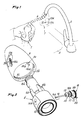
- reference numeral 1 generally designates the shower head, which is shown in Figure 1 in two positions: one position, shown in dot-and-dash lines, in which it is in contact with the end of the faucet 2 on the sink 3, and a position, shown in solid lines, in which the shower head has been gripped by a user and moved away from the faucet 2 in order to reach, with a localized jet, distant positions in the sink by taking advantage of the presence of the flexible hose 4 which is comprised within the faucet 2 and is associated, in manners described hereafter, with said shower head 1.
- the shower head 1 comprises the outer enclosure 5, which is formed as a solid of revolution which allows comfortable grip by a user and has two substantially opposite openings 5a and 5b; the central body 6, meant to convey water from the intake end, which is provided with a thread 6a for coupling to the flexible hose 4, is contained and locked within said outer enclosure.
- the disk 7 comprises the central water delivery port 7a, which is provided with the filters and aerator set 7b, and ports such 7c, 7d to discharge of the water in the form of a peripheral jet.
- the central body 6 comprises a cavity which is arranged substantially transversely to the water delivery direction and is divided into two facing portions 8 and 9 which lie on opposite sides with respect to the opening 10 which connects said cavity to the duct 11 which branches off from the water intake end.
- the cavity portion 8 is provided with a port 8a for the discharge of the water toward the duct 12, which is connected to the ports such as 7c, 7d of the disk 7 that provide the peripheral jet, and is shaped at the water intake section so as to form the surface 8b that provides a seal by abutment against the flow control element 13 connected to the rod 14, which is shown in Figure 2 in two operating positions, as detailed hereinafter.
- Said rod 14 protrudes from the bottom of the cavity portion 8, which is protected by the gasket 14a, which is locked by means of the plate 14b, and protrudes from the slot-shaped opening 15 which lies longitudinally along the wall of the outer enclosure 5: in this manner it is associated with the actuation lever 16, which will be described further hereinafter and is pivoted on the support 16a.
- Reference numeral 17 designates a covering hood which is associated with the outer enclosure 5 by insertion of a tab provided at one end of the hood in the hole 17a, with locking on the tooth 17b, and of a tab at the other end thereof in the end region of the opening 15: said hood is made of elastic material and is shaped so as to form two regions 17c, 17d which lie respectively over the end of the lever 16 and over the button 14c, which is located at the partially spherical end of the rod 14 and is associated therewith at the flat face 14d which prevents abnormal movements: said regions are highly differentiated in terms of their dimensions, so that they can be easily recognized by the user simply by touch.
- the cavity portion 9 is provided with the port 9a for delivering the water toward the portion of space 18 connected to the central port 7a of the disk 7 and is suitable to contain the movable plug or slider 19 with sealing gaskets 19a, 19b.
- Said slider 19 comprises the cavity 20, which has a water intake opening delimited by the surface 20a for providing a seal by abutment against the flow control element 13 and contains the spring 21 for actuating said flow control element 13, said spring being associated with the bottom 19c of the slider;
- the numeral 22 furthermore designates a port which is provided in the wall of the slider 19 and is suitable to connect the cavity 20 to the water delivery port 9a, and
- the numeral 23 designates a tooth which protrudes from said slider in order to keep it in position during the movements described hereinafter, being able to slide within a guide 6c formed in the central body 6.
- reference numeral 24 designates a ridge which protrudes from the internal surface of the wall of the outer enclosure 5 and comprises an inclined portion 24a and a longitudinal portion 24b; said ridge is suitable to move the slider 19 during the insertion, on assembly, of the central body 6 in the outer enclosure 5, in a manner described hereafter.
- the assembly formed by the slider 19 with the spring 21 and the flow control element 13 with the corresponding rod 14 is assembled first; then the assembly is inserted in the cavity portion 9 of the central body 6, taking care to place the end of the rod 14 at the hole provided on the bottom of the cavity portion 8, which is controlled by the gasket 14a.
- the central body 6 is inserted in the outer enclosure 5, and during the first steps of insertion, such as the one shown in Figure 4, passage is allowed by the fact that the bottom of the slider 19 and the end of the rod 14 skim the internal surface of the wall of said outer enclosure 5, in conditions of minimum axial space occupation achieved by virtue of the resiliency of the spring 21, which has assumed the maximum compression condition.
- FIG. 7 A second embodiment of the invention is now described with reference to Figures 7 and 8; such embodiment comprises the outer enclosure 25, which has the two mutually opposite openings 25a and 25b and internally contains the central body 26, which is adapted to convey water from the intake end, being provided with a thread 26a for coupling to a flexible hose such as 4.
- the central body 26 is locked within the outer enclosure 25 by virtue of the disk 27, which is associated by means of an internal thread with the thread 25c provided on the outer surface of said enclosure and is suitable to abut with said central body 26 at the water delivery end; said disk 27 of course comprises a central water delivery port, which is provided with the filters and aerator set 27a, and ports such as 27b, 27c, 27d for providing the peripheral jet.
- the central body 26 comprises, like the previously described central body 6, a cavity which is arranged substantially transversely to the water delivery direction and is divided into two facing portions 28, 29 which lie on opposite sides with respect to the opening 30 that connects said cavity to the duct 31 that branches off from the water intake end.
- the cavity portion 28 has a port 28a for delivering the water toward the duct 32, which is connected to the ports such as 27b, 27c, 27d of the disk 27 that provide the peripheral jet, and is shaped at the water intake section so as to form the surface 28b for providing a seal by abutment with the flow control element 33 connected to the rod 34, which is fully identical to the flow control element 13 of the previously described embodiment.
- Said rod 34 protrudes from the bottom of the cavity portion 28 and protrudes from the opening 35 that lies longitudinally on the wall of the outer enclosure 25 in the form of a notch which is open at the opening 25b of said enclosure; in this manner, the rod is associated with the actuation lever 36 which is pivoted to the support 36a and is covered, together with the button 34a arranged at the end of said rod, by the hood made of elastic material 37, all as described with reference to the first embodiment.
- the cavity portion 29 is provided with the port 29a for delivering the water toward the portion of space 38 that is connected to the central port of the disk 27 and is suitable to contain the fixed plug 39, which is associated therewith by virtue of the thread 39a and is provided with the sealing gaskets 39b, 39c.
- Said plug 39 comprises the cavity 40, which has a water intake opening which is delimited by the surface 40a for forming a seal by abutment with the flow control element 33, and contains the spring 41, associated with the bottom, for the actuation of said flow control element 33; reference numeral 42 furthermore designates a port which is provided in the wall of the fixed plug 39 and is suitable to connect the cavity 40 to the water delivery port 29a.
- the assembly of this embodiment of the invention first of all entails forming the assembly that comprises the plug 39 with the spring 41 and the flow control element 33 with the corresponding rod 34 and screwing said plug 39 into the seat formed within the portion of cavity 29 of the central body 6.
- Final closure occurs by screwing the disk 27, which by surrounding from the outside the enclosure 25 ensures its absolute compactness, and the operation is completed, before fully tightening the disk, by assembling the button 34a, the lever 36 and the hood 37.
- a third embodiment of the invention is now described with reference to Figure 9 and comprises the water conveyance body 43, which is provided at its intake end with a thread 43a for coupling to a flexible hose such as 4 and with which the disk 44 is associated by means of a thread at the delivery end; said disk has a central port, which is provided with the filters and aerator set 44a, and ports such as 44b, 44c for providing the peripheral jet.
- Said body 43 internally has a configuration which is fully similar to the configuration of the central body 26 of the previously described variation, and this is true also for the elements associated therewith, such as the flow control element with the corresponding rod, the fixed plug for the abutment of the contrast spring of said flow control element, and the hood for covering the actuation lever; it is merely noted that in this embodiment said rod of the flow control element protrudes from the body 43, passing through a circular hole protected by the gasket 45.
- a fourth embodiment of the invention is described with reference to Figure 10; such fourth embodiment comprises the water conveyance body 46, with a thread 46a at the intake end, and is provided, at the delivery end, with the disk 47, which has a central port provided with the filters and aerator set 47a, and ports such as 47b, 47c for providing the peripheral jet.
- the configuration of the body 46 is fully similar to the configuration of the body 43 shown in Figure 9, the only change being the fact that the plug 48 is located at the bottom of the portion 49 of the transverse cavity from which the rod of the flow control element protrudes, without altering the fact that said cavity portion is connected to the duct 50 which conveys water to the disk 47 in order to form the peripheral jet, while the water for forming the central jet reaches the portion of space 51 by arriving from the transverse cavity portion 52 whose bottom is formed monolithically within the body 46.
- a placement of the plug 48 such as the one described might also be provided in the embodiment shown in Figure 7 described earlier.
- the embodiment shown in Figure 11, described hereafter, comprises the water conveyance body 53, which has a thread 53a at the intake end and is provided, at its delivery end, with the disk 54 with a central port provided with the filters and aerator set 54a, and with ports such as 54b, 54c for providing the peripheral jet.
- the modification that the body 53 has with respect to the body 43 described in Figure 9 consists in that the transverse cavity portion 55 from the bottom of which the rod of the flow control element protrudes is connected, by means of the duct 56, to the portion of space 57 that conveys the water to the central jet, while the portion 58 of said transverse cavity is connected, by means of the duct 59, to the holes of the disk 54 that form the peripheral jet.
Landscapes
- Nozzles (AREA)
- Bathtubs, Showers, And Their Attachments (AREA)
- Combinations Of Kitchen Furniture (AREA)
- Domestic Plumbing Installations (AREA)
Abstract
Description
- The invention relates to a pull-out shower head for kitchen.
- The great diffusion achieved by so-called shower heads for kitchen is known; said shower heads are connected to a flexible hose so that they can be pulled out from faucets in order to reach distant positions within sinks, as occurs in particular in large kitchens of the professional type, and convey water with the possibility to provide discharge in the form of a central jet or of a peripheral jet by way of a simple maneuver on an appropriately provided device.
- One very common form of said shower heads provides for the presence of a substantially cylindrical portion which is connected, at one end, to a water dispensing nozzle, essentially forming a pipe-like shape which entails some problems in terms of handling by the user.
- A pull-out shower head which comprises a body whose shape allows a user to grip it easily for comfortable use in professional kitchens has also been proposed; however, it has disadvantageous characteristics owing to a certain complexity in construction and assembly.
- The aim of the present invention is to provide a pull-out shower head for kitchen which offers maximum comfort in handling and great simplicity in construction and assembly.
- This aim is achieved by a kitchen pull-out shower head, according to the invention, comprising a water conveyance body having, at its intake end, means for coupling to a flexible hose comprised within a faucet, and is associated, at its delivery end, with a disk comprising a central port and peripheral ports for water passage, characterized in that said body comprises a cavity being arranged substantially transversely to the water delivery direction and having an opening toward a duct which branches off from the water intake end and is divided into two facing portions which lie on opposite sides with respect to said opening, each portion comprising a water delivery port, one of said ports being adapted to be connected to the peripheral ports, the other port being suitable to be connected to the central water passage port that is comprised within said disk, at least one of said portions being provided with a hollow plug which comprises, at the wall, a port for connection to the water delivery port that is comprised within said portion, a flow control element being provided which has a rod which protrudes externally so as to be associated with an actuation lever, and is suitable to abut, on opposite sides, with sealing surfaces at the water intake section respectively of the portion that is not provided with the plug and of the cavity of the plug comprised within the other portion.
- Further characteristics and advantages of the invention will become better apparent from the following detailed description of preferred but not exclusive embodiments thereof, illustrated only by way of non-limitative example in the accompanying drawings, wherein:
- Figure 1 is a view of the invention during use;
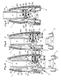
- Figure 2 is a sectional view of the invention, taken along a longitudinal plane, in the fully assembled condition;
- Figure 3 is an exploded view of the invention;
- Figures 4, 5 and 6 are views of three successive steps of the assembly of the invention;
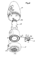
- Figures 7 and 8 are, respectively, a longitudinal sectional view and an exploded view of a second embodiment according to the invention;
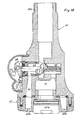
- Figures 9, 10 and 11 are longitudinal sectional views of further embodiments according to the invention.
-
- With reference to Figures 1 to 6, reference numeral 1 generally designates the shower head, which is shown in Figure 1 in two positions: one position, shown in dot-and-dash lines, in which it is in contact with the end of the
faucet 2 on thesink 3, and a position, shown in solid lines, in which the shower head has been gripped by a user and moved away from thefaucet 2 in order to reach, with a localized jet, distant positions in the sink by taking advantage of the presence of the flexible hose 4 which is comprised within thefaucet 2 and is associated, in manners described hereafter, with said shower head 1. - The shower head 1 comprises the
outer enclosure 5, which is formed as a solid of revolution which allows comfortable grip by a user and has two substantiallyopposite openings 5a and 5b; thecentral body 6, meant to convey water from the intake end, which is provided with a thread 6a for coupling to the flexible hose 4, is contained and locked within said outer enclosure. - The
central body 6, which has reinforcement fins such as 6b, is locked within theouter enclosure 5 by means of thedisk 7, which has an external thread, is associated with said outer enclosure by means of the thread 5c, and is adapted to abut against saidcentral body 6 at the water delivery end: thedisk 7 comprises the central water delivery port 7a, which is provided with the filters and aerator set 7b, and ports such 7c, 7d to discharge of the water in the form of a peripheral jet. - The
central body 6 comprises a cavity which is arranged substantially transversely to the water delivery direction and is divided into two facingportions 8 and 9 which lie on opposite sides with respect to the opening 10 which connects said cavity to theduct 11 which branches off from the water intake end. - The
cavity portion 8 is provided with a port 8a for the discharge of the water toward theduct 12, which is connected to the ports such as 7c, 7d of thedisk 7 that provide the peripheral jet, and is shaped at the water intake section so as to form the surface 8b that provides a seal by abutment against theflow control element 13 connected to therod 14, which is shown in Figure 2 in two operating positions, as detailed hereinafter. - Said
rod 14 protrudes from the bottom of thecavity portion 8, which is protected by the gasket 14a, which is locked by means of theplate 14b, and protrudes from the slot-shaped opening 15 which lies longitudinally along the wall of the outer enclosure 5: in this manner it is associated with theactuation lever 16, which will be described further hereinafter and is pivoted on thesupport 16a. -
Reference numeral 17 designates a covering hood which is associated with theouter enclosure 5 by insertion of a tab provided at one end of the hood in thehole 17a, with locking on the tooth 17b, and of a tab at the other end thereof in the end region of the opening 15: said hood is made of elastic material and is shaped so as to form two regions 17c, 17d which lie respectively over the end of thelever 16 and over the button 14c, which is located at the partially spherical end of therod 14 and is associated therewith at theflat face 14d which prevents abnormal movements: said regions are highly differentiated in terms of their dimensions, so that they can be easily recognized by the user simply by touch. - The cavity portion 9 is provided with the port 9a for delivering the water toward the portion of
space 18 connected to the central port 7a of thedisk 7 and is suitable to contain the movable plug orslider 19 withsealing gaskets - Said
slider 19 comprises thecavity 20, which has a water intake opening delimited by the surface 20a for providing a seal by abutment against theflow control element 13 and contains thespring 21 for actuating saidflow control element 13, said spring being associated with thebottom 19c of the slider; thenumeral 22 furthermore designates a port which is provided in the wall of theslider 19 and is suitable to connect thecavity 20 to the water delivery port 9a, and thenumeral 23 designates a tooth which protrudes from said slider in order to keep it in position during the movements described hereinafter, being able to slide within a guide 6c formed in thecentral body 6. - Finally,
reference numeral 24 designates a ridge which protrudes from the internal surface of the wall of theouter enclosure 5 and comprises aninclined portion 24a and a longitudinal portion 24b; said ridge is suitable to move theslider 19 during the insertion, on assembly, of thecentral body 6 in theouter enclosure 5, in a manner described hereafter. - The per se known operation of the device for switching from the central jet to the peripheral jet and vice versa is briefly described with reference to Figure 2, which illustrates the shower head in a fully assembled condition and in the operating position.
- With the faucet closed, the
spring 21 pushes theflow control element 13 against the sealing surface 8b, as shown in the lower region of Figure 2, so as to produce the central-jet condition when the faucet opens; the water, arriving from theduct 11, in fact enters thecavity 20 of theslider 19, passing through 20a, and then reaches, by following the dashed-line path of Figure 2 through theports 22 and 9a, the portion ofspace 18 that is connected to the central port 7a of thedisk 7. - If one wishes to switch the jet from central to peripheral, it is sufficient to press the button 14c, so as to move the
flow control element 13 into the condition shown in the upper region of Figure 2, i.e., in contact with the sealing surface 20a: the water traces the path shown in solid lines in Figure 2 and the peripheral jet is produced through the ports such as 7c, 7d. - The situation is maintained by virtue of the passage of the water, and if one wishes to return to the central-jet condition it is sufficient to press the end of the
lever 16, i.e., close the faucet. - The method of assembling the shower head according to the invention is of primary interest and is now described with reference to Figures 4, 5 and 6.
- The assembly formed by the
slider 19 with thespring 21 and theflow control element 13 with thecorresponding rod 14 is assembled first; then the assembly is inserted in the cavity portion 9 of thecentral body 6, taking care to place the end of therod 14 at the hole provided on the bottom of thecavity portion 8, which is controlled by the gasket 14a. - At this point, the
central body 6 is inserted in theouter enclosure 5, and during the first steps of insertion, such as the one shown in Figure 4, passage is allowed by the fact that the bottom of theslider 19 and the end of therod 14 skim the internal surface of the wall of saidouter enclosure 5, in conditions of minimum axial space occupation achieved by virtue of the resiliency of thespring 21, which has assumed the maximum compression condition. - As the insertion of the
central body 6 continues, one reaches the condition of Figure 5, in which the end of therod 14 has arranged itself at the opening 15 and can protrude from it, pushed by thespring 21. - From this moment onward, by virtue of the appropriate arrangement of the
ridge 24, the further insertion of thecentral body 6 produces the movement of theslider 19 which, appropriately guided by thetooth 23, is pushed by theportion 24a of said ridge to the active position shown in Figure 6, which is rendered stable by the contact of the portion 24b of the ridge with thebottom 19c of the slider, which has thetooth 23 in contact with an abutment and locking surface. - Final closure occurs by screwing the
disk 7, and the operation is completed, just before fully closing saiddisk 7, by assembling the button 14c, thelever 16 and thehood 17. - A second embodiment of the invention is now described with reference to Figures 7 and 8; such embodiment comprises the
outer enclosure 25, which has the two mutually opposite openings 25a and 25b and internally contains thecentral body 26, which is adapted to convey water from the intake end, being provided with athread 26a for coupling to a flexible hose such as 4. - The
central body 26 is locked within theouter enclosure 25 by virtue of thedisk 27, which is associated by means of an internal thread with the thread 25c provided on the outer surface of said enclosure and is suitable to abut with saidcentral body 26 at the water delivery end; saiddisk 27 of course comprises a central water delivery port, which is provided with the filters and aerator set 27a, and ports such as 27b, 27c, 27d for providing the peripheral jet. - The
central body 26 comprises, like the previously describedcentral body 6, a cavity which is arranged substantially transversely to the water delivery direction and is divided into two facingportions duct 31 that branches off from the water intake end. - In a manner similar to what occurs for the previously described
cavity portion 8, thecavity portion 28 has a port 28a for delivering the water toward theduct 32, which is connected to the ports such as 27b, 27c, 27d of thedisk 27 that provide the peripheral jet, and is shaped at the water intake section so as to form the surface 28b for providing a seal by abutment with theflow control element 33 connected to therod 34, which is fully identical to theflow control element 13 of the previously described embodiment. - Said
rod 34 protrudes from the bottom of thecavity portion 28 and protrudes from the opening 35 that lies longitudinally on the wall of theouter enclosure 25 in the form of a notch which is open at the opening 25b of said enclosure; in this manner, the rod is associated with theactuation lever 36 which is pivoted to thesupport 36a and is covered, together with the button 34a arranged at the end of said rod, by the hood made ofelastic material 37, all as described with reference to the first embodiment. - The
cavity portion 29 is provided with the port 29a for delivering the water toward the portion ofspace 38 that is connected to the central port of thedisk 27 and is suitable to contain thefixed plug 39, which is associated therewith by virtue of thethread 39a and is provided with the sealing gaskets 39b, 39c. - Said
plug 39 comprises thecavity 40, which has a water intake opening which is delimited by the surface 40a for forming a seal by abutment with theflow control element 33, and contains thespring 41, associated with the bottom, for the actuation of saidflow control element 33;reference numeral 42 furthermore designates a port which is provided in the wall of thefixed plug 39 and is suitable to connect thecavity 40 to the water delivery port 29a. - The assembly of this embodiment of the invention first of all entails forming the assembly that comprises the
plug 39 with thespring 41 and theflow control element 33 with thecorresponding rod 34 and screwing saidplug 39 into the seat formed within the portion ofcavity 29 of thecentral body 6. - At this point, the
central body 26 is inserted in theouter enclosure 25 and is moved to the operating condition shown in Figure 7 without encountering any obstacle, since therod 34 enters and slides in thenotch 35, which is open at the end. - Final closure occurs by screwing the
disk 27, which by surrounding from the outside theenclosure 25 ensures its absolute compactness, and the operation is completed, before fully tightening the disk, by assembling the button 34a, thelever 36 and thehood 37. - A third embodiment of the invention is now described with reference to Figure 9 and comprises the
water conveyance body 43, which is provided at its intake end with a thread 43a for coupling to a flexible hose such as 4 and with which thedisk 44 is associated by means of a thread at the delivery end; said disk has a central port, which is provided with the filters and aerator set 44a, and ports such as 44b, 44c for providing the peripheral jet. - Said
body 43 internally has a configuration which is fully similar to the configuration of thecentral body 26 of the previously described variation, and this is true also for the elements associated therewith, such as the flow control element with the corresponding rod, the fixed plug for the abutment of the contrast spring of said flow control element, and the hood for covering the actuation lever; it is merely noted that in this embodiment said rod of the flow control element protrudes from thebody 43, passing through a circular hole protected by thegasket 45. - A fourth embodiment of the invention is described with reference to Figure 10; such fourth embodiment comprises the
water conveyance body 46, with a thread 46a at the intake end, and is provided, at the delivery end, with thedisk 47, which has a central port provided with the filters and aerator set 47a, and ports such as 47b, 47c for providing the peripheral jet. - The configuration of the
body 46 is fully similar to the configuration of thebody 43 shown in Figure 9, the only change being the fact that theplug 48 is located at the bottom of theportion 49 of the transverse cavity from which the rod of the flow control element protrudes, without altering the fact that said cavity portion is connected to theduct 50 which conveys water to thedisk 47 in order to form the peripheral jet, while the water for forming the central jet reaches the portion ofspace 51 by arriving from thetransverse cavity portion 52 whose bottom is formed monolithically within thebody 46. - The shape and operation of the flow control element of course remain unchanged.
- A placement of the
plug 48 such as the one described might also be provided in the embodiment shown in Figure 7 described earlier. - The embodiment shown in Figure 11, described hereafter, comprises the
water conveyance body 53, which has a thread 53a at the intake end and is provided, at its delivery end, with thedisk 54 with a central port provided with the filters and aerator set 54a, and with ports such as 54b, 54c for providing the peripheral jet. - The modification that the
body 53 has with respect to thebody 43 described in Figure 9 consists in that thetransverse cavity portion 55 from the bottom of which the rod of the flow control element protrudes is connected, by means of theduct 56, to the portion ofspace 57 that conveys the water to the central jet, while theportion 58 of said transverse cavity is connected, by means of theduct 59, to the holes of thedisk 54 that form the peripheral jet. - A modification such as the one described above with regard to the embodiment shown in Figure 9 can also be performed in the embodiments shown in Figures 2, 7 and 10, and this is true also for the further modification that can be noticed in Figure 11, which consists of the absence of the actuation spring of the flow control element, which is otherwise unchanged.
- The described invention is susceptible of numerous other modifications and variations, all of which are within the scope of the inventive concept; all the details may further be replaced with other technically equivalent elements.
- The disclosures in Italian Patent Application No. MN2000A000013 from which this application claims priority are incorporated herein by reference.
- Where technical features mentioned in any claim are followed by reference signs, those reference signs have been included for the sole purpose of increasing the intelligibility of the claims and accordingly, such reference signs do not have any limiting effect on the interpretation of each element identified by way of example by such reference signs.
Claims (19)
- A pull-out shower head for kitchen, comprising a water conveyance body (6) which has, at its intake end, means (6a) for coupling to a flexible hose (4) which is comprised within a faucet (2), and is associated, at its delivery end, with a disk (7) which comprises a central port (7a) and peripheral ports (7c,7d) for water passage, characterized in that said body comprises a cavity (8,9) which is arranged substantially transversely to the water delivery direction and has an opening (10) toward a duct (11) which branches off from the water intake end and is divided into two facing portions (8,9) which lie on opposite sides with respect to said opening (10), each portion (8,9) comprising a water delivery port (8a,9a), one of said ports (8a) being adapted to be connected to the peripheral ports (7c,7d), the other port (9a) being suitable to be connected to the central water passage port (7a) that is comprised within said disk (7), at least a first one (9) of said portions (8,9) being provided with a hollow plug (19) which comprises, at the wall, a port (22) for connection to the water delivery port (9a) that is comprised within said portion (9), a flow control element (13) being provided which has a rod (14) which protrudes externally so as to be associated with an actuation lever (16), and is adapted to abut, on opposite sides, with sealing surfaces (18b,20a) at the water intake section respectively of the second portion (8) free from the plug (19) and of the cavity (20) of the plug (19) comprised within the first portion (9).
- The shower head according to claim 1, characterized in that it comprises an outer enclosure (5) provided with two openings (5a,5b) and the central water conveyance body (6) adapted to be contained within the outer enclosure (5) in order to be locked therein by way of the abutment disk (7) at the water delivery end which is associated with a first opening (5b) of said outer enclosure (5) and comprises the central port (7a) and the peripheral ports (7c,7d) for the passage of the water, said central body (6) being provided, at the other end for water intake which is located at the second opening (5a) of the outer enclosure (5), with the means (6a) for coupling to the flexible hose (4) comprised within the faucet (2), and comprising the cavity (8,9) which is arranged substantially transversely to the water delivery direction and is provided with the opening (10) toward the duct (11) which branches off from the water intake end, and is divided into the two facing portions (8,9) which protrude on opposite sides with respect to said opening (10), each portion (8,9) comprising a water delivery port (8a,9a), one (8a) of said ports being adapted to connect to the peripheral ports (7c,7d) while the other port (9a) is adapted to connect to the central water passage port (7a) comprised within said disk (7), at least a first one (9) of said portions being provided with the hollow plug (19) which comprises, at the wall, the port (22) for connection to the water delivery port (9a) that is comprised within said portion (9), the flow control element (13) being provided which has the rod (14) which protrudes externally so as to be associated with the actuation lever (16), said flow control element (13) being adapted to abut on opposite sides with sealing surfaces (8b,20a) at the water intake section respectively of the second portion (8) that is free from the plug and of the cavity (20) of the plug (19) that is comprised within the first portion (9).
- The shower head according to one or more of the preceding claims, characterized in that it comprises a hood (17) for covering the actuation lever (16) of the rod (14) of the flow control element (13), said hood (17) being made of elastic material and being shaped so as to form two regions (17c,17d) which are highly differentiated in terms of dimensions and lie over the end of said lever (16) and over a button (14c) located at the end of said rod, respectively.
- The shower head according to one or more of the preceding claims, characterized in that the hood (17) for covering the lever (16) for actuating the rod (14) of the flow control element (13) is provided with end tabs (17b) which are insertable in appropriately provided openings (17a) in order to lock said hood (17).
- The shower head according to one or more of the preceding claims, characterized in that the rod (14) of the flow control element has an end (14c) which is shaped like a partial sphere with a flat face which, by making contact with a similar flat face (14d) provided in the button (14c) that is in contact with it, prevents abnormal movements thereof.
- The shower head according to one or more of the preceding claims, characterized in that the hole for the outward passage of the rod of the flow control element is protected by a gasket (14a) which is locked by means of a plate (14b) which is associated with the surface that is adjacent to said hole.
- The shower head according to one or more of the preceding claims, characterized by the presence of a flow control element actuation spring (21).
- The shower head according to one or more of the preceding claims, characterized in that the outer enclosure (5) has a shape which allows it to be gripped comfortably by an operator.
- The shower head according to one or more of the preceding claims, characterized in that the outer enclosure (5) has the shape of a solid of revolution and is suitable to be gripped comfortably by an operator, with the two openings (5a,5b) at the bases.
- The shower head according to one or more of the preceding claims, characterized in that the abutment disk (7) suitable to lock the central body (6) within the outer enclosure (5) is associated by way of a thread (5c) with an opening (5b) of said enclosure (5), and comprises filters and an aerator (7b) at the central water passage port (7a).
- The shower head according to one or more of the preceding claims,
characterized in that it comprises the outer enclosure (25) provided with two openings (25a,25b) and a central water conveyance body (26) which is adapted to be contained within the outer enclosure (25) in order to be locked therein by way of the abutment disk (27) at the water delivery end, said disk (27) being associated with a first opening (25b) of said outer enclosure (25) and comprising a central port and peripheral ports (27b,27c,27d) for water passage, said central body (26) being provided, at its other end for water intake, located at the second opening of the outer enclosure, with means (26a) for coupling to a flexible hose (4) which is comprised within a faucet (2), and comprising the cavity (28,29) which is arranged substantially transversely to the water delivery direction, is provided with an opening (30) toward a duct (31) which branches off from the water intake end, and is divided into two facing portions (28,29) which lie on opposite sides with respect to said opening (30):a first portion (28), which is provided with a water delivery port (28a) which is suitable to connect to the peripheral water passage ports (27b,27c,27d) of said abutment disk (27) and is shaped, at the water intake section, so as to form a surface (28b) for sealing by abutment against a flow control element (33) which is connected to a rod (34) which protrudes from the bottom of said first portion so as to protrude from an opening (25b) which lies longitudinally on the wall of said outer enclosure (25), so as to be associated with an actuation lever (36);a second portion (29), which is provided with a water delivery port (29a) which is adapted to connect to the central water passage port of said abutment disk (27) and is suitable to contain a plug (39) which comprises a cavity (40) having, at one end, a water intake opening delimited by a surface (40a) for forming a seal by abutment against said flow control element (33) and containing a spring (41) for the actuation of said flow control element (33), and comprising, at the wall, a port (29a) for connection to said central water passage port for the delivery of the water from said second portion (29). - The shower head according to one or more of the preceding claims, characterized in that the second cavity portion (9) comprises a movable plug (19), or slider, which is suitable to be moved during the insertion of the central body (6) in the outer enclosure (5) in order to be placed in the active position and be locked thereat by a ridge (24) which protrudes from the internal surface of the wall of said outer enclosure (5), the opening (15) that lies longitudinally on the wall of the outer enclosure (5) being slot-shaped so as to allow the protrusion of the rod (14) of the flow control element (13).
- The shower head according to one or more of the preceding claims, characterized in that the abutment disk (7) suitable to lock the central body (6) within the outer enclosure (5) is associated, by means of a thread provided at its outer surface, with an opening (5b) of said enclosure (5).
- The shower head according to one or more of the preceding claims, characterized in that the slider (19) is provided with a tooth (23) which is suitable to move into the active position in contact with an abutment surface formed within the central body (6), moving within a guide formed in said central body (6).
- The shower head according to one or more of the preceding claims, characterized in that the ridge (24) that protrudes from the internal surface of the wall of the outer enclosure (5) is adapted to make contact with the bottom of the slider (19) and has:a first portion (24a), which is inclined and adapted to move said slider (19) until it reaches the active position during the insertion of the central body (6) in the outer enclosure (5) from a position in which the bottom of said slider (19) is in contact with said internal surface, said first inclined portion (24a) being arranged so as to determine the beginning of said movement substantially from the position of the central body (6) in which the rod (14) of the flow control element (13) protrudes from the opening (15) that lies longitudinally on said wall of the outer enclosure (5);a second portion (24b), which is longitudinal and suitable to arrange itself in contact with the bottom of the slider (19) in the active position.
- The shower head according to claim 1, characterized in that the second cavity portion (29) comprises a fixed plug (39), the opening (35) that lies longitudinally along the wall of the outer enclosure (25) being formed in the shape of a notch which is open at the water delivery end in order to allow the rod (34) of the flow control element (33) to protrude, the abutment disk (27) being adapted to lock the central body (26) within the outer enclosure (25) associated with said enclosure (25) by way of an internal thread which is complementary to a thread (25c) formed on the outer surface of said enclosure (25).
- The shower head according to claim 16, characterized in that the fixed plug (39) is associated with the second cavity portion (29) by means of a thread (39a).
- The shower head according to claim 16, characterized in that the fixed plug (39) is associated with the second portion (29) of cavity by forced keying.
- The shower head according to one or more of the preceding claims, characterized in that it comprises a water conveyance body (43) which has, at its intake end, means (43a) for coupling to a flexible hose (4) which is comprised within the faucet (2), and is provided, proximate to the delivery end, with a thread for connection to a disk (44) which comprises a central port and peripheral ports for water passage, said body (43) comprising a cavity (28,29) which is arranged substantially transversely to the water delivery direction and is provided with an opening toward a duct which branches off from the water intake end and is divided into two facing portions which protrude on opposite sides with respect to said opening, each portion comprising a water delivery port, one of said ports being suitable to connect to the peripheral ports, the other port being instead adapted to connect to the central water passage port comprised within said disk (44), at least one (29) of said portions being provided with a fixed hollow plug (39) which comprises, at the wall, a port for connection to the water delivery port comprised within said portion, a flow control element (33) being furthermore present which has a rod (34) which protrudes outward so as to be associated with an actuation lever (36) and being adapted to abut, on opposite sides, against sealing surfaces at the water intake section of, respectively, the portion (28) free from the plug and the cavity (40) of the plug (39) that is comprised in the other portion (29).
Applications Claiming Priority (2)
| Application Number | Priority Date | Filing Date | Title |
|---|---|---|---|
| ITMN000013 | 2000-03-10 | ||
| IT2000MN000013A ITMN20000013A1 (en) | 2000-03-10 | 2000-03-10 | REMOVABLE SHOWER FOR KITCHEN |
Publications (3)
| Publication Number | Publication Date |
|---|---|
| EP1132141A2 true EP1132141A2 (en) | 2001-09-12 |
| EP1132141A3 EP1132141A3 (en) | 2003-01-22 |
| EP1132141B1 EP1132141B1 (en) | 2009-04-08 |
Family
ID=11450203
Family Applications (1)
| Application Number | Title | Priority Date | Filing Date |
|---|---|---|---|
| EP01104569A Expired - Lifetime EP1132141B1 (en) | 2000-03-10 | 2001-03-05 | Pull-out shower head for kitchen |
Country Status (7)
| Country | Link |
|---|---|
| US (1) | US6370713B2 (en) |
| EP (1) | EP1132141B1 (en) |
| CN (1) | CN1292837C (en) |
| AT (1) | ATE427786T1 (en) |
| DE (1) | DE60138238D1 (en) |
| ES (1) | ES2323446T3 (en) |
| IT (1) | ITMN20000013A1 (en) |
Cited By (9)
| Publication number | Priority date | Publication date | Assignee | Title |
|---|---|---|---|---|
| EP1618962A1 (en) * | 2004-07-21 | 2006-01-25 | Fabrizio Nobili | Spray head for sprayers in general and particularly for manual sprayers for sinks and the like |
| EP1656997A3 (en) * | 2004-11-16 | 2006-06-07 | T & S Brass and Bronze Works, Inc. | Pre-rinse unit spray valve mechanism |
| EP1736695A1 (en) | 2005-06-24 | 2006-12-27 | Weidmann Plastics Technology AG | Valve, especially for a sanitary fitting |
| US7314189B2 (en) | 2004-01-26 | 2008-01-01 | Fabrizio Nobili | Delivery system for treated water, showerhead and supply pipe for said system |
| EP1987884A1 (en) * | 2007-05-03 | 2008-11-05 | Fabrizio Nobili | Improved shower sprayhead |
| US7607588B2 (en) | 2006-02-28 | 2009-10-27 | Fabrizio Nobili | Sink spray head with supply jet variation and flow rate regulation |
| US9545639B2 (en) | 2013-03-15 | 2017-01-17 | Delta Faucet Company | Multi-function wand assembly |
| US9962718B2 (en) | 2005-05-13 | 2018-05-08 | Delta Faucet Company | Power sprayer |
| US11267003B2 (en) | 2005-05-13 | 2022-03-08 | Delta Faucet Company | Power sprayer |
Families Citing this family (79)
| Publication number | Priority date | Publication date | Assignee | Title |
|---|---|---|---|---|
| US6843432B1 (en) * | 2000-11-17 | 2005-01-18 | Robert L. Philpott | Personal hygiene cleansing apparatus |
| EP1262240B1 (en) * | 2001-05-22 | 2004-04-14 | Weidmann Plastics Technology AG | Valve for a water discharge nozzle with a switching device |
| US20020185553A1 (en) * | 2001-06-08 | 2002-12-12 | Benstead Evan A. | Spray head |
| US6619567B1 (en) * | 2002-07-15 | 2003-09-16 | Globe Union Industrial Corp. | Structure of a flexible water tap |
| US6757921B2 (en) | 2002-07-16 | 2004-07-06 | Kohler Co. | Pull-out faucet |
| US7000854B2 (en) * | 2002-11-08 | 2006-02-21 | Moen Incorporated | Pullout spray head with single-button mode selector |
| US6738996B1 (en) * | 2002-11-08 | 2004-05-25 | Moen Incorporated | Pullout spray head with pause button |
| US6938837B2 (en) * | 2003-01-23 | 2005-09-06 | Masco Corporation Of Indiana | Faucet spray head assembly |
| US6915816B2 (en) * | 2003-03-12 | 2005-07-12 | Masco Corporation Of Indiana | Faucet spray head hose guide and retraction mechanism |
| US6789751B1 (en) * | 2003-03-25 | 2004-09-14 | Winner Double-H Co., Ltd. | Collapsible handle for a shower head |
| USD491253S1 (en) | 2003-07-17 | 2004-06-08 | Anthony Hansle | Telescoping mixer tap |
| DE10335652A1 (en) * | 2003-07-29 | 2005-02-24 | Hansgrohe Ag | Washbasin with a hair-wash shower on a pipe that is withdrawn in use from a socket fixture within the washbasin surround |
| US8939429B2 (en) | 2004-01-12 | 2015-01-27 | Masco Corporation Of Indiana | Spout assembly for an electronic faucet |
| US7997301B2 (en) | 2004-01-12 | 2011-08-16 | Masco Corporation Of Indiana | Spout assembly for an electronic faucet |
| ITMN20040005A1 (en) * | 2004-03-01 | 2004-06-01 | Amfag Spa | REMOVABLE WATER DISPENSER |
| JP2005281984A (en) * | 2004-03-26 | 2005-10-13 | San-Ei Faucet Mfg Co Ltd | Hot-cold water mixing faucet |
| US7231673B1 (en) | 2004-09-28 | 2007-06-19 | Care Giver Support Products, Llc | Portable shower stall |
| US7343930B2 (en) | 2004-12-03 | 2008-03-18 | Masco Corporation Of Indiana | Sprayer with non-faucet control |
| US20060207670A1 (en) * | 2005-03-16 | 2006-09-21 | Mike Peters | Faucet extension which makes it easier to reach the running water. |
| US7748406B2 (en) * | 2005-04-01 | 2010-07-06 | Newfrey Llc | Two handle pull-out faucet |
| US7533917B2 (en) * | 2005-04-07 | 2009-05-19 | International Truck Intellectual Property Company, Llc | Integrated kitchen unit for a mobile vehicle |
| GB0509348D0 (en) * | 2005-05-09 | 2005-06-15 | Astracast Plc | A water tap |
| US7604001B2 (en) * | 2005-06-03 | 2009-10-20 | Craghead John W | Kitchen cooktop system |
| US7753079B2 (en) | 2005-06-17 | 2010-07-13 | Masco Corporation Of Indiana | Magnetic coupling for sprayheads |
| US7909061B2 (en) | 2005-06-17 | 2011-03-22 | Masco Corporation Of Indiana | Magnetic coupling for sprayheads |
| US7162782B1 (en) | 2005-07-07 | 2007-01-16 | Masco Corporation Of Indiana | Spring retainer and installation aid |
| EP1759770B1 (en) * | 2005-08-30 | 2009-08-19 | Weidmann Plastics Technology AG | Shower |
| US8800893B2 (en) * | 2005-12-14 | 2014-08-12 | Moen Incorporated | Faucet wand |
| US7344095B1 (en) * | 2006-01-25 | 2008-03-18 | Da Yuan Sheng Industrial Co., Ltd. | Water sprayer having two water output manners |
| US7871020B2 (en) | 2006-01-26 | 2011-01-18 | Masco Corporation Of Indiana | Faucet spray head with volume control |
| WO2007092850A2 (en) | 2006-02-06 | 2007-08-16 | Masco Corporation Of Indiana | Power sprayer |
| CH698984B1 (en) * | 2006-02-09 | 2009-12-31 | Weidmann Plastics Tech Ag | Pull-out spray. |
| CN100382829C (en) * | 2006-03-01 | 2008-04-23 | 王信锁 | Bladder cancer treating Chinese medicine prepn |
| US7717362B2 (en) * | 2006-03-06 | 2010-05-18 | Brasstech, Inc. | Pull-down spray head with metal shell |
| US8162236B2 (en) | 2006-04-20 | 2012-04-24 | Masco Corporation Of Indiana | Electronic user interface for electronic mixing of water for residential faucets |
| US8118240B2 (en) | 2006-04-20 | 2012-02-21 | Masco Corporation Of Indiana | Pull-out wand |
| US7331536B1 (en) * | 2006-07-14 | 2008-02-19 | Globe Union Industrial Corp. (Guic) | Shower head |
| US20080060709A1 (en) * | 2006-09-13 | 2008-03-13 | Ming-Dang Shieh | Adjustable water-dispersing device for a faucet |
| US7380731B1 (en) * | 2006-09-13 | 2008-06-03 | Da Yuan Sheng Industrial Co., Ltd. | Water sprayer having two water different spraying modes |
| US7909269B2 (en) * | 2006-09-19 | 2011-03-22 | Kohler Co. | Faucet spray control assembly |
| US8152078B2 (en) | 2006-10-25 | 2012-04-10 | Masco Corporation Of Indiana | Faucet spray head |
| US20080122691A1 (en) * | 2006-11-27 | 2008-05-29 | Carani Sherry L | Tracking system and method with multiple time zone selector, dynamic screens and multiple screen presentations |
| USD574930S1 (en) | 2007-02-13 | 2008-08-12 | Newfrey Llc | Spout body |
| USD573697S1 (en) | 2007-02-26 | 2008-07-22 | Newfrey Llc | Spout |
| USD574469S1 (en) | 2007-02-26 | 2008-08-05 | Newfrey Llc | Faucet body |
| US20100155639A1 (en) * | 2007-07-09 | 2010-06-24 | Zhou Huasong | Switching unit for pushbutton of kitchen water faucet |
| US9272295B2 (en) * | 2008-02-12 | 2016-03-01 | Kohler Co. | Sprayer assembly |
| US7766260B2 (en) * | 2008-02-12 | 2010-08-03 | Wen-Yi Lin | Showerhead |
| KR101039709B1 (en) * | 2008-10-20 | 2011-06-08 | 김종구 | Water valve |
| US8087640B2 (en) * | 2009-04-01 | 2012-01-03 | Luis Bassols | Flow valve for example for faucets |
| CA2677866C (en) * | 2009-08-25 | 2013-02-26 | Globe Union Industrial Corp. | Removable shower head |
| CN101642734B (en) * | 2009-09-09 | 2012-10-31 | 厦门松霖科技有限公司 | Lever switching shower and water outlet control method |
| US8448667B2 (en) | 2009-10-19 | 2013-05-28 | Masco Corporation Of Indiana | Multi-function pull-out wand |
| WO2011079805A1 (en) * | 2009-12-31 | 2011-07-07 | 厦门松霖科技有限公司 | Toggle switching shower head for kitchen |
| CN101773881B (en) * | 2009-12-31 | 2012-09-05 | 厦门松霖科技有限公司 | Kitchen sprinkler capable of being switched by shifting |
| KR101117488B1 (en) | 2010-04-29 | 2012-02-24 | 주식회사 킴스코파쎄 | a faucet |
| CN104254653B (en) | 2012-04-20 | 2016-04-20 | 德尔塔阀门公司 | Comprise the water tap that capacitor induction type can pull out rod |
| CN102671784B (en) * | 2012-05-10 | 2014-10-15 | 厦门松霖科技有限公司 | Valve group switched by push button and shower head using valve group |
| US9242262B2 (en) * | 2012-05-25 | 2016-01-26 | Delta Faucet Company | Body spray with extending sprayhead |
| US9181685B2 (en) | 2012-07-27 | 2015-11-10 | Kohler Co. | Magnetic docking faucet |
| US9284723B2 (en) | 2012-07-27 | 2016-03-15 | Kohler Co. | Magnetic docking faucet |
| US9259743B2 (en) | 2013-03-14 | 2016-02-16 | Kohler Co. | Splashless spray head |
| TWI509176B (en) * | 2013-06-28 | 2015-11-21 | Alexander Yeh Ind Co Ltd | Wall faucet outlet switch structure |
| WO2015048436A1 (en) * | 2013-09-26 | 2015-04-02 | As Ip Holdco, Llc | Faucet-integrated touch-free soap dispensing systems |
| US9175459B2 (en) * | 2013-12-26 | 2015-11-03 | Global Union Industrial Corp. | Water supply device with double supply modes |
| DE102014202474B3 (en) * | 2014-02-11 | 2015-06-25 | Hansgrohe Se | Shower head with valve |
| CN204083263U (en) * | 2014-08-25 | 2015-01-07 | 厦门建霖工业有限公司 | Bathtub water outlet switching construction |
| KR20190004370A (en) | 2014-09-10 | 2019-01-11 | 글로벌 마케팅 엔터프라이즈(지엠이) 리미티드 | Water toy |
| ES2664811T3 (en) * | 2015-03-06 | 2018-04-23 | Amfag S.R.L. | Removable spray head with magnetic coupling system |
| CN205013826U (en) * | 2015-08-31 | 2016-02-03 | 厦门建霖工业有限公司 | Multi -functional structure of individual palpation button |
| CN205013833U (en) * | 2015-09-09 | 2016-02-03 | 厦门松霖科技有限公司 | Individual palpation button circulation switching components |
| US9707572B2 (en) | 2015-12-18 | 2017-07-18 | Kohler Co. | Multi-function splashless sprayhead |
| CN106000689B (en) * | 2016-07-28 | 2018-12-25 | 厦门建霖健康家居股份有限公司 | Double-button shower and its working method |
| CN106763889A (en) * | 2017-01-03 | 2017-05-31 | 恺霖卫浴科技(厦门)有限公司 | A kind of difunctional bubbler of Automatic-reset |
| CN107269884B (en) * | 2017-06-27 | 2023-05-30 | 开平市汉顺洁具实业有限公司 | Go out water structure and play water structure's pull-out head with reset function |
| US10704239B2 (en) | 2018-05-29 | 2020-07-07 | Brian Richard ABOOD | Adjustable shower head assembly |
| KR102063927B1 (en) * | 2019-04-19 | 2020-01-08 | 송명훈 | Shower device for sink faucet |
| US11865557B2 (en) | 2019-07-08 | 2024-01-09 | Benoit Poirier | Flexible shower head |
| CN113152597B (en) * | 2021-04-01 | 2023-01-13 | 浙江凯玛卫浴有限公司 | Water tap capable of adjusting flow direction at will |
Citations (4)
| Publication number | Priority date | Publication date | Assignee | Title |
|---|---|---|---|---|
| CH661306A5 (en) | 1984-07-23 | 1987-07-15 | Visentin Spa | Shower for domestic use |
| DE9314443U1 (en) | 1993-09-24 | 1993-12-02 | H. Weidmann Ag, Rapperswil, St. Gallen | Water outlet for a sanitary fitting |
| EP0732148A2 (en) | 1995-03-17 | 1996-09-18 | Hansa Metallwerke Ag | Multiple function shower head |
| EP0933136A2 (en) | 1998-01-30 | 1999-08-04 | Friedrich Grohe Aktiengesellschaft | Valve for a water discharge nozzle |
Family Cites Families (8)
| Publication number | Priority date | Publication date | Assignee | Title |
|---|---|---|---|---|
| US3722799A (en) * | 1971-06-16 | 1973-03-27 | Modern Faucet Mfg Co | Adjustable shower head assembly with diverter valve |
| US4117979A (en) * | 1977-04-15 | 1978-10-03 | Speakman Company | Showerhead |
| CH661303A5 (en) * | 1984-11-14 | 1987-07-15 | Matisa Materiel Ind Sa | APPARATUS FOR HANDLING A RAILWAY APPARATUS PANEL. |
| CH681731A5 (en) * | 1990-01-26 | 1993-05-14 | Kugler Fonderie Robinetterie | |
| CN1054080C (en) * | 1995-09-07 | 2000-07-05 | 华东理工大学 | Three-way channel combined water coal slurry gasification nozzle with cyclone |
| US5860599A (en) * | 1997-08-27 | 1999-01-19 | Lin; Wen-Yi | Shower head assembly |
| US6296011B1 (en) * | 1999-04-14 | 2001-10-02 | Kohler Co. | Fluid valve |
| US6290147B1 (en) * | 2000-09-19 | 2001-09-18 | Moen Incorporated | Pullout faucet wand button mechanism |
-
2000
- 2000-03-10 IT IT2000MN000013A patent/ITMN20000013A1/en unknown
-
2001
- 2001-03-05 ES ES01104569T patent/ES2323446T3/en not_active Expired - Lifetime
- 2001-03-05 US US09/797,573 patent/US6370713B2/en not_active Expired - Lifetime
- 2001-03-05 DE DE60138238T patent/DE60138238D1/en not_active Expired - Lifetime
- 2001-03-05 EP EP01104569A patent/EP1132141B1/en not_active Expired - Lifetime
- 2001-03-05 AT AT01104569T patent/ATE427786T1/en not_active IP Right Cessation
- 2001-03-09 CN CNB011112050A patent/CN1292837C/en not_active Expired - Lifetime
Patent Citations (4)
| Publication number | Priority date | Publication date | Assignee | Title |
|---|---|---|---|---|
| CH661306A5 (en) | 1984-07-23 | 1987-07-15 | Visentin Spa | Shower for domestic use |
| DE9314443U1 (en) | 1993-09-24 | 1993-12-02 | H. Weidmann Ag, Rapperswil, St. Gallen | Water outlet for a sanitary fitting |
| EP0732148A2 (en) | 1995-03-17 | 1996-09-18 | Hansa Metallwerke Ag | Multiple function shower head |
| EP0933136A2 (en) | 1998-01-30 | 1999-08-04 | Friedrich Grohe Aktiengesellschaft | Valve for a water discharge nozzle |
Cited By (13)
| Publication number | Priority date | Publication date | Assignee | Title |
|---|---|---|---|---|
| US7314189B2 (en) | 2004-01-26 | 2008-01-01 | Fabrizio Nobili | Delivery system for treated water, showerhead and supply pipe for said system |
| EP1618962A1 (en) * | 2004-07-21 | 2006-01-25 | Fabrizio Nobili | Spray head for sprayers in general and particularly for manual sprayers for sinks and the like |
| EP1656997A3 (en) * | 2004-11-16 | 2006-06-07 | T & S Brass and Bronze Works, Inc. | Pre-rinse unit spray valve mechanism |
| US7150415B2 (en) | 2004-11-16 | 2006-12-19 | T&S Brass And Bronze Works, Inc. | Pre-rinse unit spray valve mechanism |
| US9962718B2 (en) | 2005-05-13 | 2018-05-08 | Delta Faucet Company | Power sprayer |
| US11267003B2 (en) | 2005-05-13 | 2022-03-08 | Delta Faucet Company | Power sprayer |
| US10618066B2 (en) | 2005-05-13 | 2020-04-14 | Delta Faucet Company | Power sprayer |
| EP1736695A1 (en) | 2005-06-24 | 2006-12-27 | Weidmann Plastics Technology AG | Valve, especially for a sanitary fitting |
| US7341239B2 (en) | 2005-06-24 | 2008-03-11 | Weidmann Plastics Technology Ag | Valve in particular for a sanitary fitting |
| US7607588B2 (en) | 2006-02-28 | 2009-10-27 | Fabrizio Nobili | Sink spray head with supply jet variation and flow rate regulation |
| EP1987884A1 (en) * | 2007-05-03 | 2008-11-05 | Fabrizio Nobili | Improved shower sprayhead |
| WO2008135184A1 (en) * | 2007-05-03 | 2008-11-13 | Fabrizio Nobili | Improved showerhead |
| US9545639B2 (en) | 2013-03-15 | 2017-01-17 | Delta Faucet Company | Multi-function wand assembly |
Also Published As
| Publication number | Publication date |
|---|---|
| CN1319456A (en) | 2001-10-31 |
| ITMN20000013A0 (en) | 2000-03-10 |
| CN1292837C (en) | 2007-01-03 |
| ES2323446T3 (en) | 2009-07-16 |
| US6370713B2 (en) | 2002-04-16 |
| ATE427786T1 (en) | 2009-04-15 |
| EP1132141A3 (en) | 2003-01-22 |
| DE60138238D1 (en) | 2009-05-20 |
| US20010020302A1 (en) | 2001-09-13 |
| ITMN20000013A1 (en) | 2001-09-10 |
| EP1132141B1 (en) | 2009-04-08 |
Similar Documents
| Publication | Publication Date | Title |
|---|---|---|
| EP1132141B1 (en) | Pull-out shower head for kitchen | |
| US7104473B2 (en) | Pull-out kitchen sprayer | |
| US8152078B2 (en) | Faucet spray head | |
| US7607588B2 (en) | Sink spray head with supply jet variation and flow rate regulation | |
| EP2384819B1 (en) | Kitchen sink sprayer | |
| US5184777A (en) | Shower with manipulable head and selective outflows | |
| JPS6023678A (en) | Sanitary single lever type mixed armature | |
| MY130747A (en) | Variable port valve plug | |
| US6276659B1 (en) | Pushbutton controlled valve | |
| US20190345699A1 (en) | Multipurpose faucet to release a water stream in two directions | |
| KR100755488B1 (en) | Multi-pass valves for combining water supply and drain pipes | |
| US20070059995A1 (en) | Single control roman tub faucet | |
| US8662107B2 (en) | Switch device for water conduit valve | |
| KR200476073Y1 (en) | Cartridge for cold water and hot water having step operation means of rotary click type | |
| US20180127959A1 (en) | Faucets providing mixed water and air flow | |
| WO2016202211A1 (en) | Labor-saving spray gun | |
| CN208997397U (en) | A kind of Lode switching valve of water route switching valve and bathtub | |
| JP2001011916A (en) | Valve device for switching waterway of faucet appliance | |
| US20130087231A1 (en) | Cold/hot water balance valve with burn-proof functions | |
| JPH11229462A (en) | Water discharge device | |
| JP2005131143A (en) | Water discharge switching structure for shower head | |
| JP2004232691A (en) | Push type faucet | |
| US20060219304A1 (en) | Increased area single handle fluid cartridge | |
| JPH11188289A (en) | Shower device | |
| US20240271398A1 (en) | Pull-out faucet and water outlet panel assembly configured to be connected to pull-out faucet |
Legal Events
| Date | Code | Title | Description |
|---|---|---|---|
| PUAI | Public reference made under article 153(3) epc to a published international application that has entered the european phase |
Free format text: ORIGINAL CODE: 0009012 |
|
| AK | Designated contracting states |
Kind code of ref document: A2 Designated state(s): AT BE CH CY DE DK ES FI FR GB GR IE IT LI LU MC NL PT SE TR |
|
| AX | Request for extension of the european patent |
Free format text: AL;LT;LV;MK;RO;SI |
|
| PUAL | Search report despatched |
Free format text: ORIGINAL CODE: 0009013 |
|
| AK | Designated contracting states |
Kind code of ref document: A3 Designated state(s): AT BE CH CY DE DK ES FI FR GB GR IE IT LI LU MC NL PT SE TR |
|
| AX | Request for extension of the european patent |
Free format text: AL;LT;LV;MK;RO;SI |
|
| 17P | Request for examination filed |
Effective date: 20030701 |
|
| AKX | Designation fees paid |
Designated state(s): AT BE CH CY DE DK ES FI FR GB GR IE IT LI LU MC NL PT SE TR |
|
| RAP1 | Party data changed (applicant data changed or rights of an application transferred) |
Owner name: AMFAG S.P.A. |
|
| 17Q | First examination report despatched |
Effective date: 20050203 |
|
| RAP3 | Party data changed (applicant data changed or rights of an application transferred) |
Owner name: AMFAG S.P.A. |
|
| GRAP | Despatch of communication of intention to grant a patent |
Free format text: ORIGINAL CODE: EPIDOSNIGR1 |
|
| GRAS | Grant fee paid |
Free format text: ORIGINAL CODE: EPIDOSNIGR3 |
|
| GRAA | (expected) grant |
Free format text: ORIGINAL CODE: 0009210 |
|
| AK | Designated contracting states |
Kind code of ref document: B1 Designated state(s): AT BE CH CY DE DK ES FI FR GB GR IE IT LI LU MC NL PT SE TR |
|
| REG | Reference to a national code |
Ref country code: GB Ref legal event code: FG4D |
|
| REG | Reference to a national code |
Ref country code: CH Ref legal event code: NV Representative=s name: PATENTANWALTSBUERO JEAN HUNZIKER AG Ref country code: CH Ref legal event code: EP |
|
| REG | Reference to a national code |
Ref country code: IE Ref legal event code: FG4D |
|
| REF | Corresponds to: |
Ref document number: 60138238 Country of ref document: DE Date of ref document: 20090520 Kind code of ref document: P |
|
| REG | Reference to a national code |
Ref country code: ES Ref legal event code: FG2A Ref document number: 2323446 Country of ref document: ES Kind code of ref document: T3 |
|
| NLV1 | Nl: lapsed or annulled due to failure to fulfill the requirements of art. 29p and 29m of the patents act | ||
| PG25 | Lapsed in a contracting state [announced via postgrant information from national office to epo] |
Ref country code: FI Free format text: LAPSE BECAUSE OF FAILURE TO SUBMIT A TRANSLATION OF THE DESCRIPTION OR TO PAY THE FEE WITHIN THE PRESCRIBED TIME-LIMIT Effective date: 20090408 Ref country code: AT Free format text: LAPSE BECAUSE OF FAILURE TO SUBMIT A TRANSLATION OF THE DESCRIPTION OR TO PAY THE FEE WITHIN THE PRESCRIBED TIME-LIMIT Effective date: 20090408 Ref country code: PT Free format text: LAPSE BECAUSE OF FAILURE TO SUBMIT A TRANSLATION OF THE DESCRIPTION OR TO PAY THE FEE WITHIN THE PRESCRIBED TIME-LIMIT Effective date: 20090908 |
|
| PG25 | Lapsed in a contracting state [announced via postgrant information from national office to epo] |
Ref country code: SE Free format text: LAPSE BECAUSE OF FAILURE TO SUBMIT A TRANSLATION OF THE DESCRIPTION OR TO PAY THE FEE WITHIN THE PRESCRIBED TIME-LIMIT Effective date: 20090708 Ref country code: NL Free format text: LAPSE BECAUSE OF FAILURE TO SUBMIT A TRANSLATION OF THE DESCRIPTION OR TO PAY THE FEE WITHIN THE PRESCRIBED TIME-LIMIT Effective date: 20090408 |
|
| PG25 | Lapsed in a contracting state [announced via postgrant information from national office to epo] |
Ref country code: DK Free format text: LAPSE BECAUSE OF FAILURE TO SUBMIT A TRANSLATION OF THE DESCRIPTION OR TO PAY THE FEE WITHIN THE PRESCRIBED TIME-LIMIT Effective date: 20090408 |
|
| PLBE | No opposition filed within time limit |
Free format text: ORIGINAL CODE: 0009261 |
|
| STAA | Information on the status of an ep patent application or granted ep patent |
Free format text: STATUS: NO OPPOSITION FILED WITHIN TIME LIMIT |
|
| PG25 | Lapsed in a contracting state [announced via postgrant information from national office to epo] |
Ref country code: BE Free format text: LAPSE BECAUSE OF FAILURE TO SUBMIT A TRANSLATION OF THE DESCRIPTION OR TO PAY THE FEE WITHIN THE PRESCRIBED TIME-LIMIT Effective date: 20090408 |
|
| 26N | No opposition filed |
Effective date: 20100111 |
|
| PG25 | Lapsed in a contracting state [announced via postgrant information from national office to epo] |
Ref country code: MC Free format text: LAPSE BECAUSE OF NON-PAYMENT OF DUE FEES Effective date: 20100331 Ref country code: GR Free format text: LAPSE BECAUSE OF FAILURE TO SUBMIT A TRANSLATION OF THE DESCRIPTION OR TO PAY THE FEE WITHIN THE PRESCRIBED TIME-LIMIT Effective date: 20090709 |
|
| GBPC | Gb: european patent ceased through non-payment of renewal fee |
Effective date: 20100305 |
|
| REG | Reference to a national code |
Ref country code: IE Ref legal event code: MM4A |
|
| PG25 | Lapsed in a contracting state [announced via postgrant information from national office to epo] |
Ref country code: IE Free format text: LAPSE BECAUSE OF NON-PAYMENT OF DUE FEES Effective date: 20100305 |
|
| PG25 | Lapsed in a contracting state [announced via postgrant information from national office to epo] |
Ref country code: GB Free format text: LAPSE BECAUSE OF NON-PAYMENT OF DUE FEES Effective date: 20100305 |
|
| PG25 | Lapsed in a contracting state [announced via postgrant information from national office to epo] |
Ref country code: CY Free format text: LAPSE BECAUSE OF FAILURE TO SUBMIT A TRANSLATION OF THE DESCRIPTION OR TO PAY THE FEE WITHIN THE PRESCRIBED TIME-LIMIT Effective date: 20090408 |
|
| PG25 | Lapsed in a contracting state [announced via postgrant information from national office to epo] |
Ref country code: LU Free format text: LAPSE BECAUSE OF NON-PAYMENT OF DUE FEES Effective date: 20100305 |
|
| PG25 | Lapsed in a contracting state [announced via postgrant information from national office to epo] |
Ref country code: TR Free format text: LAPSE BECAUSE OF FAILURE TO SUBMIT A TRANSLATION OF THE DESCRIPTION OR TO PAY THE FEE WITHIN THE PRESCRIBED TIME-LIMIT Effective date: 20090408 |
|
| REG | Reference to a national code |
Ref country code: FR Ref legal event code: PLFP Year of fee payment: 16 |
|
| REG | Reference to a national code |
Ref country code: FR Ref legal event code: PLFP Year of fee payment: 17 |
|
| REG | Reference to a national code |
Ref country code: FR Ref legal event code: PLFP Year of fee payment: 18 |
|
| PGFP | Annual fee paid to national office [announced via postgrant information from national office to epo] |
Ref country code: IT Payment date: 20200218 Year of fee payment: 20 Ref country code: DE Payment date: 20200218 Year of fee payment: 20 |
|
| PGFP | Annual fee paid to national office [announced via postgrant information from national office to epo] |
Ref country code: CH Payment date: 20200221 Year of fee payment: 20 |
|
| PGFP | Annual fee paid to national office [announced via postgrant information from national office to epo] |
Ref country code: FR Payment date: 20200220 Year of fee payment: 20 |
|
| PGFP | Annual fee paid to national office [announced via postgrant information from national office to epo] |
Ref country code: ES Payment date: 20200401 Year of fee payment: 20 |
|
| REG | Reference to a national code |
Ref country code: CH Ref legal event code: PFUS Owner name: AMFAG S.P.A., IT Free format text: FORMER OWNER: AMFAG S.P.A., IT |
|
| REG | Reference to a national code |
Ref country code: DE Ref legal event code: R071 Ref document number: 60138238 Country of ref document: DE |
|
| REG | Reference to a national code |
Ref country code: CH Ref legal event code: PL |
|
| REG | Reference to a national code |
Ref country code: ES Ref legal event code: FD2A Effective date: 20220128 |
|
| PG25 | Lapsed in a contracting state [announced via postgrant information from national office to epo] |
Ref country code: ES Free format text: LAPSE BECAUSE OF EXPIRATION OF PROTECTION Effective date: 20210306 |