EP1130833A2 - Asynchrone Wiederabtastubg für Datenübertragung - Google Patents
Asynchrone Wiederabtastubg für Datenübertragung Download PDFInfo
- Publication number
- EP1130833A2 EP1130833A2 EP01103123A EP01103123A EP1130833A2 EP 1130833 A2 EP1130833 A2 EP 1130833A2 EP 01103123 A EP01103123 A EP 01103123A EP 01103123 A EP01103123 A EP 01103123A EP 1130833 A2 EP1130833 A2 EP 1130833A2
- Authority
- EP
- European Patent Office
- Prior art keywords
- signals
- location
- signal
- generating
- phase
- Prior art date
- Legal status (The legal status is an assumption and is not a legal conclusion. Google has not performed a legal analysis and makes no representation as to the accuracy of the status listed.)
- Withdrawn
Links
Images

Classifications
-
- H—ELECTRICITY
- H04—ELECTRIC COMMUNICATION TECHNIQUE
- H04L—TRANSMISSION OF DIGITAL INFORMATION, e.g. TELEGRAPHIC COMMUNICATION
- H04L7/00—Arrangements for synchronising receiver with transmitter
- H04L7/0016—Arrangements for synchronising receiver with transmitter correction of synchronization errors
- H04L7/002—Arrangements for synchronising receiver with transmitter correction of synchronization errors correction by interpolation
- H04L7/0029—Arrangements for synchronising receiver with transmitter correction of synchronization errors correction by interpolation interpolation of received data signal
-
- H—ELECTRICITY
- H04—ELECTRIC COMMUNICATION TECHNIQUE
- H04J—MULTIPLEX COMMUNICATION
- H04J3/00—Time-division multiplex systems
- H04J3/02—Details
- H04J3/06—Synchronising arrangements
- H04J3/062—Synchronisation of signals having the same nominal but fluctuating bit rates, e.g. using buffers
- H04J3/0632—Synchronisation of packets and cells, e.g. transmission of voice via a packet network, circuit emulation service [CES]
Definitions
- This invention relates to the transport of a multiplex of sampled signals from one location to another, and more particularly relates to such transport accomplished asynchronously.
- the present invention addresses the foregoing problems raised by conventional transport and provides alternative solutions.
- the invention is useful in a communication system for transporting a plurality of sampled signals from a first location to a second location.
- one or more data signals and a set of one or more synchronously-related clock signals exist at a first location.
- One or more reference signals are generated at the first location, preferably by a reference clock.
- a phase signal is generated which represents at least an estimate of the difference in phase between one of the data clock signals and one of the reference signals.
- the one or more data signals and phase signal are transported to a second location.
- resample filters are conditioned in response to the phase signal, preferably by a filter selector. Each conditioned resample filter is responsive to the one or more data signals in order to generate one or more resampled data signals at the second location.
- Digital signal processing or analog conversion may be accomplished on these one or more resampled data signals at the second location, using the second location's reference clocks, with fidelity approaching processing with the synchronous sample clocks at the first location.
- phase signal increases the transport data by less than 0.2%, while maintaining necessary fidelity provided by synchronous processing at the first location, in one application.
- Figure 1 is a schematic block diagram of a preferred form of the present invention as operated on a single sampled signal.
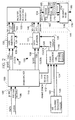
- Figure 2 is a schematic block diagram of one alternative of the present invention applied to a multiplicity of sampled signals.
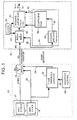
- Figure 3 is a schematic block diagram of a second, preferred, implementation of the present invention applied to a multiplicity of sampled signals.
- a preferred form of the present invention is used to transport a single data signal from a first location 10 to a second location 40.
- a source 12 of one data signal and one clock signal there is a source 12 of one data signal and one clock signal. More specifically, source 12 comprises a data signal source 14 and a clock signal source 16.
- the data signal is transmitted over an M bit bus 18, and the clock signal is transmitted over a bus 20 which also provides an input to a phase difference estimator 22. Inputs are also received by estimator 22 over a bus 26 from one or more reference clocks 24 which generate reference signals.
- Phase difference estimator 22 generates a phase signal on an output bus 28 representing at least an estimate of the difference in phase between the data clock signal on bus 20 and the reference clock signal on bus 26.
- Mux and Buffer 30 multiplexes the phase differences 28 with the data signal 18 and buffers and formats for asynchronous transport.
- Bus 32 comprises a long distance communication line which transports the multiplexed data signal and phase signal to location 40.
- a clock 42 transmits clock pulses over a bus 44 to a Buffer and Demux 46 and a resample filter 50 which interpolates the data received over a bus 48 from buffer 46.
- Clock 42 may be asynchronous with respect to other clocks shown in the system, such as data clock 16.
- the data is clocked out of buffer 46 by the clock signals on bus 44.
- Filter 50 comprises a finite impulse response (FIR) filter which interpolates based on coefficients received over an input bus 52 from a filter selector 54.
- Selector 54 includes a coefficient read only memory (ROM) 56 addressed by signals received over an address bus 58 from an address interface 60 which conditions the phase signal received on bus 28 in order to address ROM 56.
- Buffer and Demux 46 strips off the phase estimates and provides these to the Address Interface 60 over Bus 38.
- FIR finite impulse response
- filter 50 In response to the coefficients read out of ROM 56, filter 50 generates resample data signals that are transmitted over an output bus 51. Since the resampling process generates data in addition to the original M bits of data received on bus 48, the output bus 51 provides for M plus L bits of data.
- Estimator 22 may comprise the phase estimate portion of part number G802480 manufactured by TRW, Inc.
- location 100 is provided with multiple channels of multiplexed synchronously sampled data signals on a bus 106 and is provided with a high rate clock signal on a bus 108.
- Data is transmitted on bus 106 at a rate of 800 megabytes per second (in one embodiment), and the clock signal on bus 108 has a frequency of 800 MHz.
- Busses 106 and 108 provide inputs to a conventional demultiplexer 110 which separates the data and clock into individual channels, such as channels 132 and 133.
- Channel 132 comprises a pair of busses 134 and 135.
- Bus 134 transmits M bits of data and bus 135 transmits a subharmonic of the 800 MHz clock signal.
- Channel 133 comprises an M bit data bus 138 and a clock bus 139 which transmits a subharmonic of the 800 MHz clock signal.
- Demultiplexer 110 also extracts the frame synch signal transmitted on bus 106 from the data signals and supplies the frame synch-signal on a bus 112. Demultiplexer 110 also divides the 800 MHz clock signal to form a 50 MHz clock signal on an output conductor 114.
- phase estimator 116 which also divides the 50 MHz clock in order to form a 2.5 MHz clock 118. Additional inputs to phase estimator 116 are provided by coherent reference clocks 120 which provide coherent (i.e., phase aligned) clock signals over buses 122 and 124. Phase estimator 116 generates a phase signal on an output conductor 126 which represents at least an estimate of the phase difference between the reference clock signals and (a) the 50 MHz clock signal and (b) the 2.5 MHz clock signal.
- the 2.5 MHz clock signal from clock 118 provides ambiguity resolution information for the phase difference calculation.
- the phase signal generated on bus 126 provides a phase difference between the phase of the reference clock signals and the 2.5 MHz clock signal, but with fidelity to the least significant bits relative to the 50 MHz clock signal.
- the embodiment of Figure 2 can achieve a least significant bit fidelity to the phase of the 800 MHz clock signal (which is divided to form the 50 MHz clock signal).
- the phase estimator 116 may use the frame synch signal.
- ambiguity resolution may be achieved by the lowest clock rate for which resampling is to occur, that is, the lowest data clock for which the resampling function is required.
- the lowest clock rate used for ambiguity resolution must be synchronous with the 800 MHz clock. Synchronization can be accomplished by dividing the 800 MHz clock by conventional dividers (not shown).
- a phase estimator clock signal is transmitted over a bus 128 to each of several data insertion modules, such as 130 and 131.
- the phase estimate signal on bus 126 also is transmitted to each of the data insertion modules.
- the data insertion modules insert the phase signals on buses 126 as an extra bit in the data words transmitted on the channels.
- output data buses 142 and 146 transmit M plus 1 bits of data.
- Output busses 143 and 147 continue to carry subharmonics of the 800 MHz clock signal which was passed through from busses 135 and 139.
- Module 150 includes communication channels which transmit data and clock signals between location 100 and a location 160 which may be many miles from location 100.
- the illustrated channel comprises a clock bus 162 which transmits the 800 MHz clock and a data bus 164 which transmits the M plus 1 bits received on channel 142.
- Bus 164 provides an input to a demultiplexer circuit 166 which separates the data into a. data bus 170 of M bits and a phase estimate bus 168 which transmits the phase estimate signal to a selector 172 that may be identical to selector 54 shown in Figure 1.
- Coefficients are selected and provided to a resample or interpolate filter 176 over a bus 174. In the same manner described in connection with Figure 1, resample filter 176 provides resampled data signals over an output bus 180 and 800 MHz clock signals over an output bus 178.
- phase estimates were multiplexed into each data signal stream by adding an extra bit to each sample. This may have advantages, in particular regarding legacy equipment. However, this does mean redundant information is included in the transport from location 100 to location 160 (since identical phase inserts are inserted multiple times). A more efficient approach is shown in Figure 3, with each phase estimate only inserted one time into the transport.
- location 200 is provided with a multiplex of synchronously sampled data signals on a bus 206 and is provided with a high rate clock signal on a bus 208.
- Bus 206 transmits multiple channels of data signals at 800 megabytes per second (in one embodiment) and also transmits multiple channels of clock signals at 800 MHz over a bus 208.
- Buses 206 and 208 provide an input to a frame synch extract and clock divider module 210 which passes the multiple channels of data signals at 800 megabytes per second over buses 212 and passes the 800 megahertz clock signals over buses 214.
- Module 210 also extracts the frame synch signal from the data signals and transmits it over an output bus 218.
- Module 210 also divides the 800 MHz clock signal to generate a 50MHz clock signal over a bus 216.
- a phase estimator 116 receives the frame synch signal and 50 MHz clock signal, and also receives coherent (e.g., phase aligned) reference clock signals from clocks 120 over input busses 122 and 124.
- Estimator 116 includes a 2.5 MHz clock 118.
- Phase estimator 116 operates in the same manner described in connection with estimator 116 shown in Figure 2 and provides a phase estimate signal over bus 126 on a clock signal over bus 128 in the manner previously described.
- the components of Figure 3 which bear the same numbers as components shown in Figure 2 are constructed the same and operate in the same manner described in connection with Figure 2.
- the data and clocks on buses 212 and 214 are assembled into data packets by a packatize format and forward error correction (FEC) encode module 230.
- FEC forward error correction
- the phase estimate signal on bus 126 and the clock on bus 128 are also assembled into data packets by module 230. All of the packets are transmitted over a communication line 232 to location 240 which may be at a distance of many miles from location 200.
- a packet to data stream assembly, FEC decode and demultiplex - module 242 divides the data and clocks into multiple channels, including data channels 1-N and corresponding clock channels as shown. Only two pairs of the data and clock channels are illustrated in Figure 3. For example, in channel 1, data signals are transmitted over a data bus 244 and clock signals are transmitted over a clock bus 245. Similarly, in channel N, data signals are transmitted over a bus 248 and corresponding clock signals are transmitted over a bus 249.
- the phase estimate signal is recovered by module 242 and is transmitted over a bus 252 to selectors, such as selectors 254 and 255.
- selectors such as selectors 254 and 255.
- the selectors transmit coefficients over buses 258 and 259 to resample filters 262 and 263 as shown.
- Resample or interpolate filters 262 and 263 operate in the same manner as resample or interpolate filter 50 shown in Figure 1.
- resampled data signals are transmitted over buses 266 and 267, and corresponding clock signals are transmitted over buses 270 and 271.
- phase estimate signals on bus 126 must be put in packets by module 230 frequently enough to provide adequate phase estimates for selectors 254 and 255 and resample filters 262 and 263. Even at low data stream sample rates, there are, for example, greater than 50 samples of data for each phase estimate. At this point, the phase estimates are not time critical. Phase estimates may be added to the data samples with only one bit.
- phase estimates on bus 252 need not be generated frequently, and there is no urgency in aligning these estimates precisely with the data bits in the high rate serial stream, such as bus 244.
- the phase difference information on bus 252 is not time critical (relative to the high rate serial clock on bus 245). Thus, the phase estimate need not be handled and delivered with nanosecond timing alignment to the serial data on bus 244.
- the phase estimate on bus 126 may be performed on a divided down clock from the 800 MHz clock signal on bus 208.
- the estimated phase signal on bus 126 is inserted into the high rate multiplexed data stream one signal or one packet at a time for use by the multiplex data streams at location 240.
- two resampler phase estimates may be needed for ambiguity resolution, one for the highest resampling clock (e.g., 50 MHz) and one for the lowest (e.g., 2.5 MHz). These two phase estimates (modulo 360°) may be combined into a single phase estimate which extends beyond 360° (i.e., resolved ambiguity).
- the frame synch signal on bus 218 may be used for ambiguity resolution.
- selector 54 may compute the coefficients used by filter 50.
Landscapes
- Engineering & Computer Science (AREA)
- Computer Networks & Wireless Communication (AREA)
- Signal Processing (AREA)
- Multimedia (AREA)
- Computer Hardware Design (AREA)
- Time-Division Multiplex Systems (AREA)
- Synchronisation In Digital Transmission Systems (AREA)
Applications Claiming Priority (2)
| Application Number | Priority Date | Filing Date | Title |
|---|---|---|---|
| US09/516,800 US6904111B1 (en) | 2000-03-01 | 2000-03-01 | Asynchronous resampling for data transport |
| US516800 | 2000-03-01 |
Publications (2)
| Publication Number | Publication Date |
|---|---|
| EP1130833A2 true EP1130833A2 (de) | 2001-09-05 |
| EP1130833A3 EP1130833A3 (de) | 2004-01-02 |
Family
ID=24057148
Family Applications (1)
| Application Number | Title | Priority Date | Filing Date |
|---|---|---|---|
| EP01103123A Withdrawn EP1130833A3 (de) | 2000-03-01 | 2001-02-09 | Asynchrone Wiederabtastubg für Datenübertragung |
Country Status (4)
| Country | Link |
|---|---|
| US (1) | US6904111B1 (de) |
| EP (1) | EP1130833A3 (de) |
| JP (1) | JP2001268063A (de) |
| CA (1) | CA2337308C (de) |
Cited By (6)
| Publication number | Priority date | Publication date | Assignee | Title |
|---|---|---|---|---|
| WO2001089137A3 (de) * | 2000-05-17 | 2002-10-03 | Bosch Gmbh Robert | Rundfunkempfänger für den empfang von digitalen rundfunksignalen und verfahren zum empfang von digitalen rundfunksignalen |
| WO2004017544A3 (en) * | 2002-08-14 | 2004-05-21 | Oasis Silicon Systems | Communication system for sending and receiving data onto and from a network at a network frame rate using a phase locked loop, sample rate conversion, or synchronizing clocks generated from the network frame rate |
| US7106224B2 (en) | 2002-08-14 | 2006-09-12 | Standard Microsystems Corporation | Communication system and method for sample rate converting data onto or from a network using a high speed frequency comparison technique |
| US7158596B2 (en) | 2002-08-14 | 2007-01-02 | Standard Microsystems Corp. | Communication system and method for sending and receiving data at a higher or lower sample rate than a network frame rate using a phase locked loop |
| US7272202B2 (en) | 2002-08-14 | 2007-09-18 | Standard Microsystems Corp. | Communication system and method for generating slave clocks and sample clocks at the source and destination ports of a synchronous network using the network frame rate |
| WO2012103686A1 (en) * | 2011-02-01 | 2012-08-09 | Huawei Technologies Co., Ltd. | Method and apparatus for providing signal processing coefficients |
Families Citing this family (2)
| Publication number | Priority date | Publication date | Assignee | Title |
|---|---|---|---|---|
| US7203017B1 (en) * | 2003-09-23 | 2007-04-10 | Marvell International Ltd. | Timing recovery for data storage channels with buffered sectors |
| US8693601B2 (en) | 2012-01-03 | 2014-04-08 | Intel Corporation | Self-correcting multirate filter |
Family Cites Families (20)
| Publication number | Priority date | Publication date | Assignee | Title |
|---|---|---|---|---|
| DE69225320T2 (de) * | 1992-09-25 | 1998-11-19 | Ibm | Adapter zum Anschluss an ein "clear channel"-Übertragungsnetz |
| US5426643A (en) * | 1993-11-01 | 1995-06-20 | Motorola Inc. | Apparatus and method for transmitting bit synchronous data over an unreliable channel |
| US5533072A (en) * | 1993-11-12 | 1996-07-02 | International Business Machines Corporation | Digital phase alignment and integrated multichannel transceiver employing same |
| US5694174A (en) * | 1994-10-21 | 1997-12-02 | Nec Corporation | Television system capable of synchronizing a receiver with a transmitter by using a reference signal having a varying phase angle |
| FR2726713B1 (fr) * | 1994-11-09 | 1997-01-24 | Sgs Thomson Microelectronics | Circuit de transmission de donnees en mode asynchrone a frequence libre de reception calee sur la frequence d'emission |
| EP0718995A1 (de) * | 1994-12-20 | 1996-06-26 | International Business Machines Corporation | Apparat und Verfahren zur Synchronisierung von Taktsignalen für digitalen Leitungen |
| US5680422A (en) * | 1995-04-27 | 1997-10-21 | Adtran | Method and apparatus for reducing waiting time jitter in pulse stuffing synchronized digital communications |
| WO1997003508A1 (en) * | 1995-07-13 | 1997-01-30 | Sony Corporation | Data transmission method, data transmission apparatus and data transmission system |
| JPH0936871A (ja) * | 1995-07-17 | 1997-02-07 | Sony Corp | データ伝送システムおよびデータ伝送方法 |
| US5822317A (en) * | 1995-09-04 | 1998-10-13 | Hitachi, Ltd. | Packet multiplexing transmission apparatus |
| US5563891A (en) * | 1995-09-05 | 1996-10-08 | Industrial Technology Research Institute | Waiting time jitter reduction by synchronizer stuffing threshold modulation |
| DE59611151D1 (de) * | 1996-05-21 | 2004-12-30 | Keymile Ag Liebefeld | Stopfverfahren für plesiochrone datenübertragung (ii) |
| US6072810A (en) * | 1996-11-08 | 2000-06-06 | Alcatel | Method to transparently transport an incoming clock signal over a network segment, and related transmitter and receiver unit |
| JP3790329B2 (ja) * | 1997-06-27 | 2006-06-28 | 富士通株式会社 | 信号ループバック装置 |
| US5950115A (en) * | 1997-08-29 | 1999-09-07 | Adaptec, Inc. | GHz transceiver phase lock loop having autofrequency lock correction |
| KR100261295B1 (ko) * | 1997-12-03 | 2000-07-01 | 이계철 | 준안정이 고려된 디지털 위상 정렬장치 |
| US6397042B1 (en) * | 1998-03-06 | 2002-05-28 | Texas Instruments Incorporated | Self test of an electronic device |
| US6167078A (en) * | 1998-03-30 | 2000-12-26 | Motorola | Conservation of power in a serial modem |
| US6285726B1 (en) * | 1998-05-18 | 2001-09-04 | National Semiconductor Corporation | 10/100 mb clock recovery architecture for switches, repeaters and multi-physical layer ports |
| JP3085293B2 (ja) * | 1998-11-18 | 2000-09-04 | 日本電気株式会社 | データ伝送装置 |
-
2000
- 2000-03-01 US US09/516,800 patent/US6904111B1/en not_active Expired - Fee Related
-
2001
- 2001-02-09 EP EP01103123A patent/EP1130833A3/de not_active Withdrawn
- 2001-02-15 CA CA002337308A patent/CA2337308C/en not_active Expired - Fee Related
- 2001-02-19 JP JP2001041219A patent/JP2001268063A/ja active Pending
Cited By (12)
| Publication number | Priority date | Publication date | Assignee | Title |
|---|---|---|---|---|
| WO2001089137A3 (de) * | 2000-05-17 | 2002-10-03 | Bosch Gmbh Robert | Rundfunkempfänger für den empfang von digitalen rundfunksignalen und verfahren zum empfang von digitalen rundfunksignalen |
| US7702039B2 (en) | 2000-05-17 | 2010-04-20 | Robert Bosch Gmbh | Radio receiver for receiving digital radio signals and method for receiving digital radio signals |
| WO2004017544A3 (en) * | 2002-08-14 | 2004-05-21 | Oasis Silicon Systems | Communication system for sending and receiving data onto and from a network at a network frame rate using a phase locked loop, sample rate conversion, or synchronizing clocks generated from the network frame rate |
| US7106224B2 (en) | 2002-08-14 | 2006-09-12 | Standard Microsystems Corporation | Communication system and method for sample rate converting data onto or from a network using a high speed frequency comparison technique |
| US7158596B2 (en) | 2002-08-14 | 2007-01-02 | Standard Microsystems Corp. | Communication system and method for sending and receiving data at a higher or lower sample rate than a network frame rate using a phase locked loop |
| US7272202B2 (en) | 2002-08-14 | 2007-09-18 | Standard Microsystems Corp. | Communication system and method for generating slave clocks and sample clocks at the source and destination ports of a synchronous network using the network frame rate |
| EP2262138A3 (de) * | 2002-08-14 | 2011-03-09 | Standard Microsystems Corporation | Übertragungssystem zum senden und zum empfangen von daten in und aus einem netzwerk mit einer netzwerksrate unter verwendung eines phasenregelkreises, abtastratennumwandlung oder mit einer aus der netzwerksrahmenrate erzeugten taktsynchronisierung |
| CN1689258B (zh) * | 2002-08-14 | 2011-05-11 | 绿洲硅体系公司 | 用锁相环、采样速率转换在网络上收发数据的通信系统 |
| WO2012103686A1 (en) * | 2011-02-01 | 2012-08-09 | Huawei Technologies Co., Ltd. | Method and apparatus for providing signal processing coefficients |
| CN102783034A (zh) * | 2011-02-01 | 2012-11-14 | 华为技术有限公司 | 用于提供信号处理系数的方法和设备 |
| CN102783034B (zh) * | 2011-02-01 | 2014-12-17 | 华为技术有限公司 | 用于提供信号处理系数的方法和设备 |
| US9800453B2 (en) | 2011-02-01 | 2017-10-24 | Huawei Technologies Co., Ltd. | Method and apparatus for providing speech coding coefficients using re-sampled coefficients |
Also Published As
| Publication number | Publication date |
|---|---|
| JP2001268063A (ja) | 2001-09-28 |
| CA2337308A1 (en) | 2001-09-01 |
| EP1130833A3 (de) | 2004-01-02 |
| CA2337308C (en) | 2004-01-06 |
| US6904111B1 (en) | 2005-06-07 |
Similar Documents
| Publication | Publication Date | Title |
|---|---|---|
| US6085270A (en) | Multi-channel, multi-rate isochronous data bus | |
| EP2076983B1 (de) | Verfahren zur taktwiedergewinnung unter verwendung aktualisierter zeitstempel | |
| JP2964457B2 (ja) | 通信処理装置 | |
| US6631138B1 (en) | Reduced pin-count 10Base-T MAC to transceiver interface | |
| SE516082C2 (sv) | Radiotelefonikommunikationssystem som gränsar till ett system av ISDN typ | |
| JPH0621860A (ja) | 多目的デジタル信号再生処理装置 | |
| US6904111B1 (en) | Asynchronous resampling for data transport | |
| US6782007B1 (en) | TDM bus synchronization circuit and protocol and method of operation | |
| US6167048A (en) | Clock recovery for video communication over ATM network | |
| JP2005519490A (ja) | 複数のmpegデータストリームのエイリアシング及びルーティング | |
| JP2000131474A (ja) | 時刻同期システム,時刻同期システムに適用される衛星システム,時刻同期システムに適用される地上システム,時刻同期方法およびその方法をコンピュータに実行させるプログラムを記録したコンピュータ読み取り可能な記録媒体 | |
| JP6258006B2 (ja) | Ip回線を利用したsfn放送システムおよび放送ts伝送方法 | |
| CN101783725B (zh) | 一种输出同步时间的方法、装置和系统 | |
| US6717960B1 (en) | Method for reconstructing an aggregate ATM cell stream and related device | |
| CN110048764B (zh) | 传输卫星信号的方法和系统及其接收器 | |
| US9618623B2 (en) | Satellite receiver module for telecommunication equipment | |
| EP1193901A3 (de) | Verfahren und System für Rahmen- und Zeigerausrichtung von sonet Datenkanälen | |
| JP2003518874A (ja) | データ通信 | |
| US7774494B2 (en) | Audio/video router | |
| US6178470B1 (en) | Chip for CCSDS compatible serial data streams | |
| WO2004100434B1 (en) | A transform-based alias cancellation multi-channel tuner | |
| US6404771B1 (en) | Clock lead/lag extraction in an isochronous data bus | |
| US5212688A (en) | TDM expansion bus | |
| US6381226B1 (en) | Guard time reducing system in data communication from earth station to static orbit communication satellite and method thereof | |
| US6400733B1 (en) | Apparatus and method for recovery of relative signal timing |
Legal Events
| Date | Code | Title | Description |
|---|---|---|---|
| PUAI | Public reference made under article 153(3) epc to a published international application that has entered the european phase |
Free format text: ORIGINAL CODE: 0009012 |
|
| AK | Designated contracting states |
Kind code of ref document: A2 Designated state(s): AT BE CH CY DE DK ES FI FR GB GR IE IT LI LU MC NL PT SE TR |
|
| AX | Request for extension of the european patent |
Free format text: AL;LT;LV;MK;RO;SI |
|
| PUAL | Search report despatched |
Free format text: ORIGINAL CODE: 0009013 |
|
| RAP1 | Party data changed (applicant data changed or rights of an application transferred) |
Owner name: NORTHROP GRUMMAN CORPORATION |
|
| RAP1 | Party data changed (applicant data changed or rights of an application transferred) |
Owner name: NORTHROP GRUMMAN CORPORATION |
|
| AK | Designated contracting states |
Kind code of ref document: A3 Designated state(s): AT BE CH CY DE DK ES FI FR GB GR IE IT LI LU MC NL PT SE TR |
|
| AX | Request for extension of the european patent |
Extension state: AL LT LV MK RO SI |
|
| STAA | Information on the status of an ep patent application or granted ep patent |
Free format text: STATUS: THE APPLICATION HAS BEEN WITHDRAWN |
|
| 18W | Application withdrawn |
Effective date: 20040621 |