EP1130540B1 - Banding reduction in incremental printing, through use of like weights for complementary printhead regions - Google Patents
Banding reduction in incremental printing, through use of like weights for complementary printhead regions Download PDFInfo
- Publication number
- EP1130540B1 EP1130540B1 EP01105021A EP01105021A EP1130540B1 EP 1130540 B1 EP1130540 B1 EP 1130540B1 EP 01105021 A EP01105021 A EP 01105021A EP 01105021 A EP01105021 A EP 01105021A EP 1130540 B1 EP1130540 B1 EP 1130540B1
- Authority
- EP
- European Patent Office
- Prior art keywords
- odd
- group
- image
- bands
- band
- Prior art date
- Legal status (The legal status is an assumption and is not a legal conclusion. Google has not performed a legal analysis and makes no representation as to the accuracy of the status listed.)
- Expired - Lifetime
Links
Images


Classifications
-
- G—PHYSICS
- G06—COMPUTING; CALCULATING OR COUNTING
- G06K—GRAPHICAL DATA READING; PRESENTATION OF DATA; RECORD CARRIERS; HANDLING RECORD CARRIERS
- G06K15/00—Arrangements for producing a permanent visual presentation of the output data, e.g. computer output printers
- G06K15/02—Arrangements for producing a permanent visual presentation of the output data, e.g. computer output printers using printers
- G06K15/10—Arrangements for producing a permanent visual presentation of the output data, e.g. computer output printers using printers by matrix printers
- G06K15/102—Arrangements for producing a permanent visual presentation of the output data, e.g. computer output printers using printers by matrix printers using ink jet print heads
- G06K15/105—Multipass or interlaced printing
- G06K15/107—Mask selection
Definitions
- This invention relates generally to machines and procedures for printing text or graphics on printing media such as paper, transparency stock, or other glossy media; and more particularly to a scanning thermal-inkjet machine and method that construct text or images from individual ink spots created on a printing medium, in a two-dimensional pixel array.
- the invention employs print-mode techniques to optimize image quality.
- the spatial frequency or wavenumber of the banding can be raised ( i. e. the period shortened, lowered). Banding at higher spatial frequency is less visible to the human eye than banding at a low frequency.
- Another strategy is assignment of smaller printing stress ⁇ or "workload" ⁇ to the worst-performing printhead regions. Accordingly, respective performances of regions (or individual printing elements) in the printhead are advantageously monitored over its life, and the allocation of workload modified correspondingly.
- the innovations introduced in this document achieve valuable reduction in banding without resort to large numbers of passes.
- the invention moves the field of incremental printing forward by enabling high image quality without degradation of printing throughput.
- the invention is a method of generating a printmask for incremental printing of an image.
- the printing uses image-forming elements in an array.
- the image-forming elements may be nozzles in an inkjet or bubblejet printer ⁇ or may be the analogous elements in a hot-wax transfer machine, dot-matrix printer, or other piezo- or thermally-driven system.
- the method includes the step of creating a structure of bands, respectively associated with the image-forming elements and constituting the printmask.
- bands here, i. e. groups of one or more adjacent printing elements along the printing-element array, is not to be confused with the concept of "banding" ⁇ which refers to the appearance of horizontal striations or strips across an image printed on a printing medium.
- Certain specific bands within the band structure are complementary to other specific bands within the band structure.
- the term "complementary" here means either geometrically related, as for instance by symmetry with respect to the overall array, or functionally related in a way that is analogous to such a geometrical relation.
- Another step is specifying a relatively low usage percentage for at least one particular band in which the operation of at least one image-forming element is identified as being problematic.
- Yet another step is specifying a like relatively low usage percentage for another band, in which all image-forming elements are well performing, that is respectively complementary to each "at least one" particular band.
- complementarity in structuring the duty-cycle relationships along a printhead (as defined in the course of designing a printmask) is a very powerful tool in shaping the profiles of inking density, as mentioned earlier, to obtain smaller discontinuities than possible heretofore.
- Mask smoothness is improved and with it the smooth blending of swath irregularities, particularly such irregularities within the printing-element array ( i. e. , rather than at its ends).
- the technique can also be employed to minimize swath-boundary coalescence.
- the creating step includes setting a number N of actual printing passes desired and establishing an effective spatial-frequency multiplier M desired for the image.
- the complementary bands include bands that are binary opposites.
- these binary-opposite bands are in alternate groups of the band structure as listed above.
- the like-low-percentage specifying step tend to smooth the mask and produce smoother output printing of the image.
- the at least one particular band be associated with image-forming elements known to be problematic in operation.
- the at least one particular band is chosen substantially independent of location of the image-forming elements in the array.
- the method includes the step of monitoring printing operation to identify the bands that are problematic.
- the at least one particular band include a band that is associated with image-forming elements which are not at either end of the array.
- the at least one particular band also include a band which is associated with image-forming elements at at least one end of the array.
- the method include the step of assigning a common usage percentage to all the image-forming elements associated with each band, respectively.
- the assigning step includes the two specifying steps.
- the invention form a method for printing an image using a printmask generated by the method of the first main aspect or facet of the invention.
- the printing method includes executing plural passes of a printhead over a print medium.
- Each pass forms a swath of marks on the medium.
- the method includes, between printing passes of the printhead, stepping the printing medium by a step distance that varies as between steps.
- the invention is apparatus for generating and using a printmask for incremental printing of an image.
- the printing uses image-forming elements in an array, and the array has two ends.
- the apparatus includes some means for creating a geometrical structure of bands, respectively associated with the image-forming elements and constituting the printmask. For purposes of generality and breadth in discussing the invention, these means will be called simply the "creating means”.
- the apparatus also includes some means for specifying a relatively low usage percentage for at least a first and a second particular bands which are defined to be complementary each other(85), said first an second bands are associated with image-forming elements wherein the operation of at least one image forming elements in the first band is identified as being problematic and the operation of all the image forming elements in the second band are well performing. Again for breadth and generality these means will be termed the "specifying means".
- the apparatus includes some means for applying the printmask in said printing. These means, for the reason suggested above, will be called the “applying means”.
- this second aspect of the invention is unique in addressing problems of mask smoothness and reducing associated image patterning well within the boundaries of the printing-element array.
- the apparatus also include some means for specifying a relatively low usage percentage for at least one particular band that is associated with image-forming elements that are at one or the other of the ends of the array.
- the combination of improving image quality both within and at the ends of the array is considered particularly potent.
- the apparatus further include some means defining an optimized multipass printmode having nonconstant media advance among passes.
- the optimized multipass printmode uses the printmask.
- the apparatus include a printhead, and some means for passing the printhead over a printing medium multiple times, each pass forming a swath of marks on such medium.
- the printmask includes some means for spacing edges of each swath well away from edges of substantially every other swath so that substantially no two swath edges coincide on the medium.
- the invention is amenable to implementation in a great variety of products. It can be embodied in a printer/plotter that includes a main case 1 (Fig. 1) with a window 2, and a left-hand pod 3 which encloses one end of the chassis. Within that enclosure are carriage-support and -drive mechanics and one end of the printing-medium advance mechanism, as well as a pen-refill station with supplemental ink cartridges.
- the printer/plotter also includes a printing-medium roll cover 4, and a receiving bin 5 for lengths or sheets of printing medium on which images have been formed, and which have been ejected from the machine.
- a bottom brace and storage shelf 6 spans the legs which support the two ends of the case 1.
- an entry slot 7 for receipt of continuous lengths of printing medium 4. Also included are a lever 8 for control of the gripping of the print medium by the machine.
- a front-panel display 11 and controls 12 are mounted in the skin of the right-hand pod 13. That pod encloses the right end of the carriage mechanics and of the medium advance mechanism, and also a printhead cleaning station. Near the bottom of the right-hand pod for readiest access is a standby switch 14.
- a cylindrical platen 41 (Fig. 2) ⁇ driven by a motor 42, worm 43 and worm gear 44 under control of signals from a digital electronic processor ⁇ rotates to drive sheets or lengths of printing medium 4A in a medium-advance direction. Print medium 4A is thereby drawn out of the print-medium roll cover 4.
- a pen-holding carriage assembly 20 carries pens back and forth across the printing medium, along a scanning track ⁇ perpendicular to the medium-advance direction ⁇ while the pens eject ink.
- the medium 4A thus receives inkdrops for formation of a desired image, and is ejected into the print-medium bin 5.
- the image may be a test pattern of numerous color patches or swatches 56, for reading by an optical sensor to generate calibration data.
- test patterns are for use in monitoring for and detecting printing elements (e. g. nozzles) that are performing poorly or not at all.
- a small automatic optoelectronic sensor 51 rides with the pens on the carriage and is directed downward to obtain data about pen condition (nozzle firing volume and direction, and interpen alignment).
- the sensor 51 can readily perform optical measurements 65, 81, 82 (Fig. 10); suitable algorithmic control 82 is well within the skill of the art, and may be guided by the discussions in the present document.
- a very finely graduated encoder strip 36 is extended taut along the scanning path of the carriage assembly 20 and read by another, very small automatic optoelectronic sensor 37 to provide position and speed information 37B for the microprocessor.
- One advantageous location for the encoder strip 36 is immediately behind the pens.
- a currently preferred position for the encoder strip 33 (Fig. 3), however, is near the rear of the pen-carriage tray ⁇ remote from the space into which a user's hands are inserted for servicing of the pen refill cartridges.
- the sensor 37 is disposed with its optical beam passing through orifices or transparent portions of a scale formed in the strip.
- the pen-carriage assembly 20 is driven in reciprocation by a motor 31 ⁇ along dual support and guide rails 32, 34 ⁇ through the intermediary of a drive belt 35.
- the motor 31 is under the control of signals from the digital processor.
- the pen-carriage assembly includes a forward bay structure 22 for pens ⁇ preferably at least four pens 23-26 holding ink of four different colors respectively. Most typically the inks are yellow in the leftmost pen 23, then cyan 24, magenta 25 and black 26.
- Another increasingly common system has inks of different colors that are actually different dilutions for one or more common chromatic colors, in the several pens.
- different dilutions of black may be in the several pens 23-26.
- both plural-chromatic-color and plural-black pens may be in a single printer, either in a common carriage or plural carriages.
- a rear tray 21 carrying various electronics.
- the colorimeter carriage too has a rear tray or extension 53 (Fig. 3), with a step 54 to clear the drive cables 35.
- Figs. 1 through 3 most specifically represent a system such as the Hewlett Packard printer/plotter model "DesignJet 2000CP", which does not include the present invention. These drawings, however, also illustrate certain embodiments of the invention, and ⁇ with certain detailed differences mentioned below ⁇ a printer/plotter that includes preferred embodiments of the invention.
- This implementation varies the distance by which the print medium is advanced, in plural-pass printmodes.
- the advance is best changed frequently ⁇ in fact, most often it is changed between each pair of successive passes.
- the point is to create a greater number of different locations for the edges of swaths.
- the first operation described will be a three-pass mode that is conventional.
- the beginning b and end e of the swath are formed by the two ends of the overall printhead. As successive passes occur, inking is completed progressively for each swath segment.
- segments A , B and C are each partially inked during a first pass (Fig. 5) of the present example. Previous inking in the upper two segments A and B occurs in earlier passes, and the example here picks up with a representative segment C .
- the first pass shown in Fig. 5 is also the first pass in which segment C receives any ink.
- swath segments B , C and D are each partially inked; and in a third pass, swath segments C , D and E are each partially inked.
- segment C receives no ink at all in this pass; in other words, after the third pass, inking of segment C is finished.
- segment C is completely inked, from start to finish, in three passes ⁇ namely, the first, second and third passes of the first cycle. Each of these passes provides one-third of the total inking for segment C .
- Each of the other segments D , E , F , G and H similarly is inked in three passes ⁇ cycling between the numbered passes in the drawing thus: 123, then 231, 312, and then starting again with 123. Furthermore each pass is inked by the same groups of printing elements (nozzles). Each pass provides one-third of the total colorant placed on the printing medium.
- the interfaces (dashed horizontal lines i 1-2, i 2-3, i 3-1) between passes appear at a spatial periodicity of a third of the swath height.
- the spatial periodicity may also be expressed in reciprocal terms ⁇ that is, in terms of spatial frequency or wavenumber.
- ⁇ is, in terms of spatial frequency or wavenumber.
- variable advance can be used to double the spatial frequency of the banding.
- Both the underlying three-pass operation and the doubling of frequency are examples only; other frequency multiples as well as other numbers of passes are possible.
- Swath segment A will now be identified as two narrower segments J and K (Fig. 6). Remaining segments, too, are subdivided due to the effects of the printhead positions illustrated - yielding segments N through X ⁇ or previously printing positions not shown, to produce segments L and M .
- the advance differs between each successive pair of passes.
- regions of the swath that are completed by two, or three, or four passes: for example two for segment Q ; three for N , P , R and T ; four for O and S .
- the regions of the image are filled by cycling between passes thus: 12, 123, 1234, 234, 34, 3412, 12, 123 . . . .
- the number of possible combinations of nozzle groupings that print a region of the swath is larger (seven rather than only three).
- the present invention deals with the construction of printmasks.
- the main principle consists of dividing the mask into NxMx2 horizontal bands, and assigning a constant usage to each of the bands. To illustrate this, some examples follow.
- Example one 8-pass Mask that minimizes swath-boundary coalescence
- ink density will look like a stair step function, with 16 steps, therefore making the same impression as if we were using a 16-pass printmode.
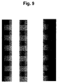
- FIG. 8 A real sample of example one appears as Fig. 8, and a counter example, in which nozzle weighting is not compensated, as Fig. 9. Note stripes of different densities in the printmask that do not appear in Fig. 8. Also note the apparent 16-pass printing in Fig. 8 (this is what the user will see while the machine is printing), versus the default 8-pass appearance shown in Fig. 9.
- Example two 6-pass Mask that minimizes swath-boundary coalescence
- '1a' determines a 116% usage for the rest of 'a' bands
- '6c' determines also a 116% usage for the rest of 'c' bands
- '1b' and '6b' determine a 125% usage for the rest of the 'b' bands.
- the detection can be achieved by several means:
- a hardware device made up of an infrared LED and a sensor. The resulting reading can be correlated not only to the fact that a nozzle is firing or not, but also to the consistency or the trajectory of the fired drop.
- the invention divides masks into multiple bands, and assigns a single usage percentage to all the nozzles in each band.
- a swath band is weighted below nominal.
- 'a-even' and 'b-odd' are complementary, as well as 'a-odd' and 'b-even'.
- 3x and 4x apparent frequencies although complementary is not so simple a rule. What also may appear is a simple mathematical rule that establishes exactly the weight for each complementary band.
- the method to operate is first to assign low weights to those printhead regions that must address coalescence problems, or to those regions of the pen that have been detected performing poorly. Then additional, complementary low weights are assigned, in order to compensate for mask smoothness.
- Figs. 12 and 13 show actual weight data for a printhead that was automatically given complementary weights, demonstrating directly how the system is capable of improving balance or symmetry.
- Figs. 14 and 15 are comparable to Figs. 8 and 9 but are simulations, for a very strongly enlarged small segment of a single swath ⁇ rather than actual printouts.
- Electronic simulations of the masking process do not take into account nonlinearities introduced by e. g. each drop of ink expanding on the media, interacting with neighboring drops etc.; however, as they are in black-and-white and very greatly enlarged, they may be helpful in appreciating the differences in performance.
- the invention helps to enable meaningful use of portions of each printing-element array that are performing below nominal ⁇ but to do so without making the resulting relatively substandard performance needlessly conspicuous.
- the printout can be made to appear as if there were, for example, twice as many passes as actually there are ⁇ as set forth particularly in the companion Zapata document.
- the mask can be changed, and automatically, according to the health of pen. Output quality improves because error is better distributed.
- Fig. 10 Before discussion of details in the block diagrammatic showing of Fig. 10, a general orientation to that drawing will be offered.
- most portions 70, 73,75-78 across the center, including the printing stage 4A-51 at far right, are generally conventional and represent the context of the invention in an inkjet printer/plotter.
- the lower portions 171-188 of Fig. 10 represent most of the concepts introduced in the related Zapata document, and serving here both as a representative implementation of the present invention and also as an inventive combination with the unique features of the present invention.
- the three main blocks 171, 176, 181 are drawn overlapping to symbolize the conceptually overlapped character of functions in these blocks.
- the swath-edge spacing means 171, wavenumber (1/ ⁇ ) varying means 176, and nozzle-combination varying or increasing means 181 are most preferably integrated with one another, so that these features of the invention are practiced in combination together.
- the accepted wavenumber symbol "1/ ⁇ " has been used to represent spatial frequency, " ⁇ " to represent variation, and "2 ⁇ ” to represent doubling.
- the spatial-frequency varying means 176 appear labeled as ⁇ (1/ ⁇ ) and the preferred spatial-frequency doubling means 177 as 2 ⁇ (1/ ⁇ ).
- the pen-carriage assembly is represented separately at 20 (Fig. 10) when traveling to the left 16 while discharging ink 18, and at 20' when traveling to the right 17 while discharging ink 19. It will be understood that both 20 and 20' represent the same pen carriage.
- the previously mentioned digital processor 71 provides control signals 20B to fire the pens with correct timing, coordinated with platen drive control signals 42A to the platen motor 42, and carriage drive control signals 31A to the carriage drive motor 31.
- the processor 71 develops these carriage drive signals 31A based partly upon information about the carriage speed and position derived from the encoder signals 37B provided by the encoder 37.
- the codestrip 33 thus enables formation of color inkdrops at ultrahigh precision during scanning of the carriage assembly 20 in each direction ⁇ i. e. , either left to right (forward 20') or right to left (back 20).
- New image data 70 are received 191 into an image-processing stage 73, which may conventionally include a contrast and color adjustment or correction module 76 and a rendition, scaling etc. module 77.
- a printmasking module 74 typically including a stage 61 for specific pass and nozzle assignments.
- the latter stage 61 performs generally conventional functions, but in accordance with certain aspects of the present invention particularly includes means 171 for defining or creating a geometrical band structure.
- the band structure established in the creating means 171 is conditioned or configured 187 by "low-usage specifying means" 84, which according to the present invention particularly and primarily includes means 85 for specifying internal bands whose condition calls for low usage ⁇ though like means 86 for specifying end bands are preferably also included.
- Information for driving the specifying means is derived by a module 63 that controls 80 the final output stage 78 to print nozzle test patterns for reading by the sensor 51, Fig. 10 (or if preferred to eject inkdrops selectively into an optical detector, not shown, that senses the drops directly, e. g. while in flight).
- the resulting sensor signal 65 is monitored in a monitoring module 72.
- That module operates according to a program 81 for reading the sensor signal, and another program stage 82 that measures the signals, and compares some signals with others, to determine inking levels and thereby determine the performance for each band of the printheads.
- the results of these measurements are massaged in a control stage 83, deriving an operating signal 68 for the previously introduced specifying means 84.
- the means represented by the several operational blocks 63, 72, 83, 61, 84 of the present invention ⁇ as well as the conventional modules 73, 74, 74, 78, and also the swath-characteristic-varying functions 171, 176, 181 as shown ⁇ are implemented within integrated circuits 71. Given the statements of function and the swath diagrams presented in this document, an experienced programmer of ordinary skill in this field can prepare suitable programs for operation of the circuits.
- the integrated circuits 71 may be part of the printer itself, as for example an application-specific integrated circuit (ASIC), or may be program data in a read-only memory (ROM) ⁇ or during operation may be parts of a programmed configuration of operating modules in the central processing unit (CPU) of a general-purpose computer that reads instructions from a hard drive.
- ASIC application-specific integrated circuit
- ROM read-only memory
- CPU central processing unit
- RIP raster image processor
- the system first retrieves 101 (Fig. 11) its operating program appropriately ⁇ i. e. , by reading instructions from memory in case of a firmware or software implementation, or by simply operating dedicated hardware in case of an ASIC or like implementation.
- the method proceeds to generation 102 of a printmask ⁇ through three major substeps of band-structure creation 103, establishment of the complements 111, and smoothing 114 based upon measurement 115 of nozzle performance.
- the apparatus proceeds with printing 124, through iteration 127 of the operational steps 125, 126.
Description
- This invention relates generally to machines and procedures for printing text or graphics on printing media such as paper, transparency stock, or other glossy media; and more particularly to a scanning thermal-inkjet machine and method that construct text or images from individual ink spots created on a printing medium, in a two-dimensional pixel array. The invention employs print-mode techniques to optimize image quality.
-
- (a) Overview - The latest large-format printer-plotters,
and smaller desktop printers as well, have a very strong need for
throughput. The principal current objectives include:
- making printheads as long as possible, in the printing-medium advance direction ("PAD"), to increase the dimension of each swath in that same direction; and
- reducing the number of passes.
- (b) Spatial-frequency effects in banding - A persistent problem in incremental printing is conspicuously visible banding or patterning, which arises from a great variety of causes. Generally these causes are associated with repetitive phenomena that are inherent in the swath-based natured of such printing. Garcia, in the following EP published application nos. 0999516, 0990528 and 0998117, particularly addresses problems of patterning in the lateral or transverse dimension, i. e. parallel to the scan axis. He points out that such patterning is especially objectionable when it occurs at spatial periodicities to which the human eye is particularly sensitive.Garcia shows that such banding can be rendered very inconspicuous at normal reading distances by moving its periodicity to roughly 3 cm (1 inch), or preferably a bit longer. This can be accomplished by tiling printmasks of those widths.Unfortunately that technique is not now readily applicable to the longitudinal dimension ― i. e. to the direction parallel to the print-medium advance axis. The reason is that, generally, largest current-day printheads are only about 2½ cm (1 inch) long in that direction.Within the corresponding available range of spatial frequencies, banding in the lower three-quarters of that range (used in single-pass through four-pass printmodes) is quite conspicuous. Unfortunately the current trend toward reducing the number of passes used for printing each image segment ― to enhance overall printing throughput ― militates toward use of precisely that part of the range.
- (c) Swath-interface effects ― Some banding along the print-medium
advance axis arises at the interfaces between swaths ― due
to the advance errors and "PAD" errors mentioned above, and due to
ink-media interactions such as coalescence or print-medium expansion.
Earlier documents such as Doval's have pointed out that
repetitive, small failures of abutment themselves introduce
banding (though extremely tiny imprecisions or variations in abutment
can be helpful).
Swath-abutment irregularities may represent the single most
conspicuous form or type of banding effect. When one swath edge
is closely abutted to another, the abutment is almost always
imperfect ― leading to either a shallow gap between swaths or a
shallow overprint where they overlap.Also the two swaths are generally not exactly the same in
darkness or color saturation, adding another element of contrast
along the interface. Such problems are aggravated by a high or
abrupt gradient of wetness along the edge of a just-deposited
swath, when an abutting swath is formed soon after.So-called "PAD error" has attracted particular attention in
part because some modern pens are subject to a concentration of
aiming errors at the ends of the pen ― most classically outboard-aimed
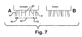
nozzles 91 (right-hand "A" view, Fig. 7) as distinguished
from the great majority of more centrally disposed nozzles 90.This higher density of errors, with systematic outboard aim,
results from the greater difficulty of maintaining TAB-tape nozzle
arrays planar, in comparison with the metal nozzle plates used
earlier. In some heads, particularly at the ends of the array,
the tape is typically wrapped around the adjacent ends of the
printhead ― causing the tape to curl very slightly.The outboard aim in pens of this type increases 93 the
overall dimension of the pixel swath in the print-medium-advance
axis, beyond the
nominal width 92. Typically this overall increase has been on the order of two or three rows.As a result, when adjacent swaths that should neatly abut are printed with a nominal advance of the print-medium-advance mechanism, those swaths will instead overlap slightly. This occurs because anerror region 93 in one of the swaths projects into a region which should be occupied by the other swath.EP Pubished application no. 761453 describes a method for operating an inkjet printer with a curved platen, wherein the printing of markin on the printing medium is performed in several passes of the printhead whereby the medium is advanced between passes. During a pass central nozzles are fired more often than nozzles at the periphery of the printhead. Printing during a single pass is thus performed in bands whereby the amount of ink placed in central bands is higher than in peripheral bands. - (d) Internal effects - Not all banding problems, however,
occur at swath boundaries. Some result simply from nozzle PAD
problems, and these nozzle irregularities can be entirely internal
to the swath (right-hand "B" view, Fig. 7).
Internal patterns, in turn, can be formed by repetitive
coincidences of nozzle irregularities. Prior systematic procedures
placed particular irregularly-performing pairs (or other
groups) of printhead elements into conjunction ― with respect to
the printing medium ― over and over.As an example, the Hewlett Packard Company printer product
known as the Model 2000C uses two-pass bidirectional printmodes ―
each pixel row being printed by two separate nozzles. At 24 rows
per millimeter (600 dots per inch, dpi), a 12.7 mm (half inch)
pen, has 300 nozzles.Ordinarily
nozzles number 1 and 151 contribute drops to the same image row ― using a 61/3 mm (quarter inch) advance and, again, a two-pass, 300-nozzle printmode. Every 61/3 mm these same two nozzles are paired.Ifnozzles 1 and 151 when used in combination form a noticeable band effect, this effect is highly visible to the user ― because it is present in a repeating pattern, roughly every 6 mm or quarter inch. For example, if both nozzles happen to be directed well away from their nominal target pixel row, then that pixel row will appear unprinted (at least in the particular color in which the head in question prints), rather than the nominal double-printed.Another kind of band effect can be caused by an interaction of nozzles that are adjacent or nearby. For example assume thatnozzle number 5 is aimed "low" (toward the nominal target row for nozzle 6). If nozzle 6 is aimed accurately, its target row will be double-printed.If in addition nozzle 156 is also aimed accurately but nozzle 157 is aimed "high" (i. e. both toward the target row for nozzle 156), then in the printed image the common pixel row for nozzles 6 and 156 will be quadruple-printed ― while the adjacent rows above and below will each be single-printed rather than the nominal (double printed).In short, banding within swaths results from repetitive coincidences between irregularly printing elements within each combination. Patterning arises from repetitive, systematic operation.Objectionable patterning is subject to quantitative effects. Thus some printmasking approaches to patterning in effect simply dilute repetition within an environment of a greater number of alternative states. - (e) Multipass printmode solutions ― Heretofore a common strategy for dealing with all these problems has been to increase the number of passes used to print each image segment. This strategy, however, degrades printing throughput. It is therefore disadvantageous in the present market, which is increasingly more demanding. This marketplace is characterized by continuously escalating consumer perceptions of what constitutes an acceptable overall image-printing time.
- (f) Conclusion ― Thus failure to effectively address problems of banding in printmodes using low numbers of passes has continued to impede achievement of uniformly excellent inkjet printing ― at high throughput. Thus important aspects of the technology used in the field of the invention remain amenable to useful refinement.
-
- The present invention introduces such refinement. Before proceeding to a relatively rigorous introduction of the invention, this section first presents an informal orientation to some insights which may in a sense have been a part of the making of the invention.
- To make banding effects less conspicuous, the spatial frequency or wavenumber of the banding can be raised (i. e. the period shortened, lowered). Banding at higher spatial frequency is less visible to the human eye than banding at a low frequency.
- Garcia's previously mentioned technique works because the visual response characteristic peaks ― so that low frequencies, too, are less visible. For the ranges currently available with
printheads 2% cm long, and less, however, what is most effective is to resort to the higher frequencies. - Another strategy is assignment of smaller printing stress ― or "workload" ― to the worst-performing printhead regions. Accordingly, respective performances of regions (or individual printing elements) in the printhead are advantageously monitored over its life, and the allocation of workload modified correspondingly.
- As to the previously mentioned problems associated with abutting swaths, these can be mitigated very greatly by shaping ink-density profiles into smaller discontinuities. One favorable result is to minimize swath-boundary coalescence.
- None of these approaches penalizes mask smoothness. Moreover it is still possible to react to changes in performance over the life of each printhead.
- In general the innovations introduced in this document achieve valuable reduction in banding without resort to large numbers of passes. In these ways the invention moves the field of incremental printing forward by enabling high image quality without degradation of printing throughput.
- With the foregoing preliminary observations in mind, this summary now moves on to somewhat more-formal discussion of the invention.
- In preferred embodiments of its first major independent facet or aspect, the invention is a method of generating a printmask for incremental printing of an image. The printing uses image-forming elements in an array. (The image-forming elements may be nozzles in an inkjet or bubblejet printer ― or may be the analogous elements in a hot-wax transfer machine, dot-matrix printer, or other piezo- or thermally-driven system.)
- The method includes the step of creating a structure of bands, respectively associated with the image-forming elements and constituting the printmask. The term "bands" here, i. e. groups of one or more adjacent printing elements along the printing-element array, is not to be confused with the concept of "banding" ― which refers to the appearance of horizontal striations or strips across an image printed on a printing medium.
- The phrase "respectively associated" here is not meant to suggest that a single band is associated with each single image-forming element respectively, although this type of direct correspondence is encompassed within the association. More typically some number of the elements, such as (merely by way of example) five to fifty elements, make up each band.
- Certain specific bands within the band structure are complementary to other specific bands within the band structure. The term "complementary" here means either geometrically related, as for instance by symmetry with respect to the overall array, or functionally related in a way that is analogous to such a geometrical relation.
- This concept of complementary bands will become clear to people skilled in this field, through consideration of the examples presented in this document. Further clarification will appear from the purposes of the complementary relationship, also as set forth in this document.
- Another step is specifying a relatively low usage percentage for at least one particular band in which the operation of at least one image-forming element is identified as being problematic. Yet another step is specifying a like relatively low usage percentage for another band, in which all image-forming elements are well performing, that is respectively complementary to each "at least one" particular band.
- The foregoing may represent a description or definition of the first aspect or facet of the invention in its broadest or most general form. Even as couched in these broad terms, however, it can be seen that this facet of the invention importantly advances the art.
- In particular, the use of complementarity in structuring the duty-cycle relationships along a printhead (as defined in the course of designing a printmask) is a very powerful tool in shaping the profiles of inking density, as mentioned earlier, to obtain smaller discontinuities than possible heretofore. Mask smoothness is improved and with it the smooth blending of swath irregularities, particularly such irregularities within the printing-element array (i. e., rather than at its ends). The technique can also be employed to minimize swath-boundary coalescence.
- Although the first major aspect of the invention thus significantly advances the art, nevertheless to optimize enjoyment of its benefits preferably the invention is practiced in conjunction with certain additional features or characteristics. In particular, preferably the creating step includes setting a number N of actual printing passes desired and establishing an effective spatial-frequency multiplier M desired for the image.
- With these preparations then is included the step of defining an overall number B of bands, associated with the image-forming elements and constituting the printmask. This number B is equal to the product B = N x M x 2, in which the numeral "2" accounts for the presence of odd and even image-forming elements, and in which the bands appear in the printmask in this order:
- first group of M bands, odd and even,
- second group of M bands, odd and even,
- next group of M bands, odd and even,
- . . .
- next group of M bands, odd and even,
- (N - 1)th group of M bands, odd and even,
- Nth group of M bands, odd and even.
-
- When this first preference is observed, then a related secondary preference is that the complementary bands include bands that are binary opposites. In addition these binary-opposite bands are in alternate groups of the band structure as listed above.
- If the related secondary preference just described is also observed, then a yet further preferred form of the invention is limited to the use of N = 8 passes, and M = 2 spatial-frequency multiplication. In this case there are therefore 8 groups of 2 bands, odd and even; and the complementary bands include:
- the first group, odd, and the second, fourth, sixth and eighth groups, even;
- the first group, even, and the second, fourth, sixth and eighths groups, odd;
- the second group, odd, and the third, fifth and seventh groups, even;
- the second group, even, and the third, fifth and seventh groups, odd;
- the third group, odd, and the fourth, sixth and eighth groups, even;
- the third group, even, and the fourth, sixth and eighth groups, odd;
- the fourth group, odd, and the fifth and seventh groups, even;
- the fourth group, even, and the fifth and seventh groups, odd;
- the fifth group, odd, and the sixth and eighth groups, even;
- the fifth group, even, and the sixth and eighth groups, odd;
- the sixth group, odd, and the seventh group, even;
- the sixth group, even, and the seventh group, odd;
- the seventh group, odd, and the eighth group, even;
- the seventh group, even, and the eighth group, odd.
-
- Reverting to the first main aspect of the invention, another preference is that the like-low-percentage specifying step tend to smooth the mask and produce smoother output printing of the image. Another preference is that the at least one particular band be associated with image-forming elements known to be problematic in operation.
- If this criterion of problematic elements is used, then preferably the at least one particular band is chosen substantially independent of location of the image-forming elements in the array. Furthermore in the "problematic element" case preferably the method includes the step of monitoring printing operation to identify the bands that are problematic.
- Yet another preference, related to the first main facet or aspect of the invention, is that the at least one particular band include a band that is associated with image-forming elements which are not at either end of the array. On the other hand, in this case it is desirable that the at least one particular band also include a band which is associated with image-forming elements at at least one end of the array.
- A still further preference is that the method include the step of assigning a common usage percentage to all the image-forming elements associated with each band, respectively. In this case the assigning step includes the two specifying steps.
- An additional preference is that the invention form a method for printing an image using a printmask generated by the method of the first main aspect or facet of the invention. In this case the printing method includes executing plural passes of a printhead over a print medium.
- Each pass forms a swath of marks on the medium. In addition the method includes, between printing passes of the printhead, stepping the printing medium by a step distance that varies as between steps.
- In preferred embodiments of its second major independent facet or aspect, the invention is apparatus for generating and using a printmask for incremental printing of an image. The printing uses image-forming elements in an array, and the array has two ends.
- The apparatus includes some means for creating a geometrical structure of bands, respectively associated with the image-forming elements and constituting the printmask. For purposes of generality and breadth in discussing the invention, these means will be called simply the "creating means".
- The apparatus also includes some means for specifying a relatively low usage percentage for at least a first and a second particular bands which are defined to be complementary each other(85), said first an second bands are associated with image-forming elements wherein the operation of at least one image forming elements in the first band is identified as being problematic and the operation of all the image forming elements in the second band are well performing. Again for breadth and generality these means will be termed the "specifying means".
- In addition the apparatus includes some means for applying the printmask in said printing. These means, for the reason suggested above, will be called the "applying means".
- The foregoing may represent a description or definition of the second aspect or facet of the invention in its broadest or most general form. Even as couched in these broad terms, however, it can be seen that this facet of the invention importantly advances the art.
- In particular, this second aspect of the invention is unique in addressing problems of mask smoothness and reducing associated image patterning well within the boundaries of the printing-element array.
- When the preference just described is in use, a further preference is that the apparatus also include some means for specifying a relatively low usage percentage for at least one particular band that is associated with image-forming elements that are at one or the other of the ends of the array. The combination of improving image quality both within and at the ends of the array is considered particularly potent.
- Another preference related directly to the second main aspect of the invention is that the apparatus further include some means defining an optimized multipass printmode having nonconstant media advance among passes. In this case also the optimized multipass printmode uses the printmask.
- In this latter case, a still further preference is that the apparatus include a printhead, and some means for passing the printhead over a printing medium multiple times, each pass forming a swath of marks on such medium. In this case the printmask includes some means for spacing edges of each swath well away from edges of substantially every other swath so that substantially no two swath edges coincide on the medium.
- All of the foregoing operational principles and advantages of the present invention will be more fully appreciated upon consideration of the following detailed description, with reference to the appended drawings, of which:
-
- Fig. 1 is a perspective or isometric view of a printer/plotter that is and that incorporates one preferred embodiment of the invention ― though the invention is equally applicable with respect to smaller, desktop types of printers in the consumer market;
- Fig. 2 is a like view, but enlarged, of portions of a printing engine ― particularly including the printing-medium advance mechanism ― within the Fig. 1 printer plotter;
- Fig. 3 is a like view, but somewhat less enlarged, of a bigger portion of the print engine;
- Fig. 4 is a diagram, highly schematic, of the printing-element (e. g. nozzle) array of a representative printhead, as it would be effectively subdivided for a conventional three-pass printmode ― and also corresponding to the subdivided structure of a single resulting printed swath on a printing medium, with the heights of the consistent pixel advance and fixed printing-medium advance;
- Fig. 5 is an analogous diagram of six printed swaths as formed using the Fig. 4 conventional three-pass mode;
- Fig. 6 is a diagram like Fig. 5 but for a three-pass mode according to one preferred embodiment of the present invention, using two systematically selected different advance distances in alternation ― the successive passes in this drawing being shown offset slightly from left to right for clarity only, as they are arrayed in a common vertical alignment when actually printed;
- Fig. 7 is an elevational diagrammatic showing of a nozzle array with systematic outboard-aiming PAD error in the "A" view and with currently more representative random PAD error in the "B" view;
- Fig. 8 is a specimen printout corresponding to "example one" (in the "Detailed Description" section of this document) ― with nozzle weighting compensated in complementary patterns according to the present invention;
- Fig. 9 is a like specimen printout but with the nozzle weighting not compensated;
- Fig. 10 is a schematic block diagram, focusing upon the functional blocks within the program-performing circuits of the preferred embodiment;
- Fig. 11 is a program flow chart illustrating operation of preferred embodiments for some method aspects of the invention;
- Fig. 12 is a graph of nozzle weights vs. nozzle number (i. e. position along the length of the print-element array), with the weights complementarily compensated in accordance with preferred embodiments of the invention;
- Fig. 13 is a like graph for weights that are not complementarily compensated;
- Fig. 14 is a simulated printout, corresponding very generally to Fig. 8 ― with complementary nozzle weights; and
- Fig. 15 is a like simulation without complementary weighting.
-
- The invention is amenable to implementation in a great variety of products. It can be embodied in a printer/plotter that includes a main case 1 (Fig. 1) with a
window 2, and a left-hand pod 3 which encloses one end of the chassis. Within that enclosure are carriage-support and -drive mechanics and one end of the printing-medium advance mechanism, as well as a pen-refill station with supplemental ink cartridges. - The printer/plotter also includes a printing-
medium roll cover 4, and areceiving bin 5 for lengths or sheets of printing medium on which images have been formed, and which have been ejected from the machine. A bottom brace and storage shelf 6 spans the legs which support the two ends of thecase 1. - Just above the print-
medium cover 4 is anentry slot 7 for receipt of continuous lengths ofprinting medium 4. Also included are alever 8 for control of the gripping of the print medium by the machine. - A front-panel display 11 and controls 12 are mounted in the skin of the right-hand pod 13. That pod encloses the right end of the carriage mechanics and of the medium advance mechanism, and also a printhead cleaning station. Near the bottom of the right-hand pod for readiest access is a
standby switch 14. - Within the
case 1 andpods 3, 13 a cylindrical platen 41 (Fig. 2) ― driven by amotor 42,worm 43 andworm gear 44 under control of signals from a digital electronic processor ― rotates to drive sheets or lengths ofprinting medium 4A in a medium-advance direction.Print medium 4A is thereby drawn out of the print-medium roll cover 4. - Meanwhile a pen-holding
carriage assembly 20 carries pens back and forth across the printing medium, along a scanning track ― perpendicular to the medium-advance direction ― while the pens eject ink. The medium 4A thus receives inkdrops for formation of a desired image, and is ejected into the print-medium bin 5. - As indicated in the drawing, the image may be a test pattern of numerous color patches or swatches 56, for reading by an optical sensor to generate calibration data. For present purposes, such test patterns are for use in monitoring for and detecting printing elements (e. g. nozzles) that are performing poorly or not at all.
- A small automatic
optoelectronic sensor 51 rides with the pens on the carriage and is directed downward to obtain data about pen condition (nozzle firing volume and direction, and interpen alignment). Thesensor 51 can readily performoptical measurements algorithmic control 82 is well within the skill of the art, and may be guided by the discussions in the present document. - A very finely graduated
encoder strip 36 is extended taut along the scanning path of thecarriage assembly 20 and read by another, very small automaticoptoelectronic sensor 37 to provide position andspeed information 37B for the microprocessor. One advantageous location for theencoder strip 36 is immediately behind the pens. - A currently preferred position for the encoder strip 33 (Fig. 3), however, is near the rear of the pen-carriage tray ― remote from the space into which a user's hands are inserted for servicing of the pen refill cartridges. For either position, the
sensor 37 is disposed with its optical beam passing through orifices or transparent portions of a scale formed in the strip. - The pen-
carriage assembly 20 is driven in reciprocation by amotor 31 ― along dual support andguide rails drive belt 35. Themotor 31 is under the control of signals from the digital processor. - Naturally the pen-carriage assembly includes a
forward bay structure 22 for pens ― preferably at least four pens 23-26 holding ink of four different colors respectively. Most typically the inks are yellow in theleftmost pen 23, thencyan 24,magenta 25 and black 26. - Another increasingly common system, however, has inks of different colors that are actually different dilutions for one or more common chromatic colors, in the several pens. Thus different dilutions of black may be in the several pens 23-26. As a practical matter, both plural-chromatic-color and plural-black pens may be in a single printer, either in a common carriage or plural carriages.
- Also included in the pen-
carriage assembly 20 is arear tray 21 carrying various electronics. The colorimeter carriage too has a rear tray or extension 53 (Fig. 3), with a step 54 to clear thedrive cables 35. - Figs. 1 through 3 most specifically represent a system such as the Hewlett Packard printer/plotter model "DesignJet 2000CP", which does not include the present invention. These drawings, however, also illustrate certain embodiments of the invention, and ― with certain detailed differences mentioned below ― a printer/plotter that includes preferred embodiments of the invention.
- For further preliminary orientation, this section now introduces a representative implementation of the preferred embodiments of the present invention. Preferred embodiments themselves are discussed in
section 3 below. - The present section corresponds to portions of the Zapata patent document mentioned earlier. Further details are available in that document.
- This implementation varies the distance by which the print medium is advanced, in plural-pass printmodes. The advance is best changed frequently ― in fact, most often it is changed between each pair of successive passes.
- The point is to create a greater number of different locations for the edges of swaths. Following is an example for a three-pass printmode: the first operation described will be a three-pass mode that is conventional.
- In considering such a mode, it is helpful to think of the dimension h (Fig. 4) of the printed swath in the printing-medium-advance axis (which is roughly the same as the printhead height) as divided into three equal segments A, B and C. The three respective equal heights of these printed swath segments are the printing-medium and data advances.
- The beginning b and end e of the swath are formed by the two ends of the overall printhead. As successive passes occur, inking is completed progressively for each swath segment.
- For instance segments A, B and C are each partially inked during a first pass (Fig. 5) of the present example. Previous inking in the upper two segments A and B occurs in earlier passes, and the example here picks up with a representative segment C.
- The first pass shown in Fig. 5 is also the first pass in which segment C receives any ink. In a second pass, swath segments B, C and D are each partially inked; and in a third pass, swath segments C, D and E are each partially inked.
- In the next "first pass" ― i. e. in the first pass of the second cycle shown in Fig. 5 ― segments D, E and F are each partially inked. Hence segment C receives no ink at all in this pass; in other words, after the third pass, inking of segment C is finished.
- Therefore it can be appreciated that segment C is completely inked, from start to finish, in three passes ― namely, the first, second and third passes of the first cycle. Each of these passes provides one-third of the total inking for segment C.
- Each of the other segments D, E, F, G and H (and A and B as well) similarly is inked in three passes ― cycling between the numbered passes in the drawing thus: 123, then 231, 312, and then starting again with 123. Furthermore each pass is inked by the same groups of printing elements (nozzles). Each pass provides one-third of the total colorant placed on the printing medium.
- The interfaces (dashed horizontal lines i1-2, i2-3, i3-1) between passes appear at a spatial periodicity of a third of the swath height. The spatial periodicity may also be expressed in reciprocal terms ― that is, in terms of spatial frequency or wavenumber. Thus expressed, the value (measured in "per-swathheight" units) is the reciprocal of the period ― namely, three.
- At each of these interfaces, the end of one swath coincides with the beginning of another. For instance at interface i3-1 the topmost full swath A-B-C ends and swath D-E-F begins. Banding effects related to swath boundaries accordingly have wavenumber 3 per swathheight (this may be written 3/swathheight, or 3 swath-height-1).
- Now to compare with this conventional fixed-advance three-pass mode, a variable advance can be used to double the spatial frequency of the banding. Both the underlying three-pass operation and the doubling of frequency are examples only; other frequency multiples as well as other numbers of passes are possible.
- Swath segment A will now be identified as two narrower segments J and K (Fig. 6). Remaining segments, too, are subdivided due to the effects of the printhead positions illustrated - yielding segments N through X ― or previously printing positions not shown, to produce segments L and M.
- To achieve this frequency doubling in a three-pass mode, the advance differs between each successive pair of passes. In the example, the stroke alternates between advancing 1/6 of a swath (as from the first pass to the second) and 3/6 = 1/2 of a swath (as from the second to the third).
- This way the swath ends e1, e2, e3 and beginnings b3, b4, b1, b2 never coincide. Instead each swath end or beginning always stands alone, so that these features occur at a one-sixth spatial periodicity ― or in other words with wavenumber 6/swathheight.
- In addition, there are now regions of the swath that are completed by two, or three, or four passes: for example two for segment Q; three for N, P, R and T; four for O and S. In other words, for the illustrated printmode the regions of the image are filled by cycling between passes thus: 12, 123, 1234, 234, 34, 3412, 12, 123 . . . . The number of possible combinations of nozzle groupings that print a region of the swath is larger (seven rather than only three).
- The scheme described here produces not only doubling of the spatial frequency but also ― for a printmode with any odd number of passes ― elimination of coincident swath beginnings and ends. Variation of advance can produce not only doubling but other spatial-frequency multiplications too. The procedures outlined in this section offer several benefits, and a possible drawback, all discussed at some length in the earlier-mentioned Zapata document.
- The present invention deals with the construction of printmasks. The main principle consists of dividing the mask into NxMx2 horizontal bands, and assigning a constant usage to each of the bands. To illustrate this, some examples follow.
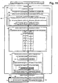
- If we only want to make a mask that puts less ink at the swath boundaries for an 8-pass printmode and want to make it look like a 16-pass printmode, we break the mask up into 8x2x2 horizontal bands. This stands for 8 passes, having 2x apparent banding frequency and specifying separately the odd from the even nozzles.
- We may assign weights to each band:
Swath band 1a 1b 2a 2b 3a 3b 4a 4b Odd nozzles 600 1000 1000 1000 1000 1000 1000 1000 Even nozzles 600 1000 1000 1000 1000 1000 1000 1000 Swath band 5a 5b 6a 6b 7a 7b 8a 8b Odd nozzles 1000 1000 1000 1000 1000 1000 1000 600 Even nozzles 1000 1000 1000 1000 1000 1000 1000 600 - These weights will correspond to a certain percentage of usage:
Swath band 1a 1b 2a 2b 3a 3b 4a 4b Odd nozzles 60% 106% 106% 106% 106% 106% 106% 106% Even nozzles 60% 106% 106% 106% 106% 106% 106% 106% Swath band 5a 5b 6a 6b 7a 7b 8a 8b Odd nozzles 106% 106% 106% 106% 106% 106% 106% 60% Even nozzles 106% 106% 106% 106% 106% 106% 106% 60% - Note that the remaining 40% of usage that '1a' does not do, is absorbed by all the other bands, from '2a' to '8a'. The same happens with '1b' to '7b': they absorb the remaining 40% of usage that we removed from '8b'. Because both '1a' and '8b' have the same weight, all the remaining bands result in the same percentage of usage, 106%. This is very important, because it provides smoothness to the mask. More of it appears in the next examples.
- When this mask is used for printing, ink density will look like a stair step function, with 16 steps, therefore making the same impression as if we were using a 16-pass printmode.
- A real sample of example one appears as Fig. 8, and a counter example, in which nozzle weighting is not compensated, as Fig. 9. Note stripes of different densities in the printmask that do not appear in Fig. 8. Also note the apparent 16-pass printing in Fig. 8 (this is what the user will see while the machine is printing), versus the default 8-pass appearance shown in Fig. 9.
- This is a very similar example, but the goal is to make this one look like an 18-pass printmode. We must then break the mask up into 6x3x2 horizontal bands, standing for 6 passes, having 3x apparent banding frequency and specifying separately the odd from the even nozzles.
- Again, the process might start by assigning weights to each band:
Swath band 1a 1b 1c 2a 2b 2c Odd nozzles 200 500 1000 1000 1000 1000 Even nozzles 300 500 1000 1000 1000 1000 Swath band 3a 3b 3c 4a 4b 4c Odd nozzles 1000 1000 1000 1000 1000 1000 Even nozzles 1000 1000 1000 1000 1000 1000 Swath band 5a 5b 5c 6a 6b 6c Odd nozzles 1000 1000 1000 1000 500 200 Even nozzles 1000 1000 1000 1000 500 200 - These weights will correspond to a certain percentage of usage:
Swath band 1a 1b 1c 2a 2b 2c Odd nozzles 20% 50% 116% 116% 125% 116% Even nozzles 20% 50% 116% 116% 125% 116% Swath band 3a 3b 3c 4a 4b 4c Odd nozzles 116% 125% 116% 116% 125% 116% Even nozzles 116% 125% 116% 116% 125% 116% Swath band 5a 5b 5c 6a 6b 6c Odd nozzles 116% 125% 116% 116% 50% 20% Even nozzles 116% 125% 116% 116% 50% 20% - Again, '1a' determines a 116% usage for the rest of 'a' bands, and '6c' determines also a 116% usage for the rest of 'c' bands. But '1b' and '6b' determine a 125% usage for the rest of the 'b' bands. This change has broken the mask evenness, introducing image quality artifacts. Here the mask weighting must be done accurately, in order to insure a perfectly smooth mask.
- Following the present invention, the above 6-pass mask is not correct. In order to make it right, '1b' and '6b' must be w eighted to 580, that the 32% less usage of '1b', added to the 32% less usage of '6b' is absorbed, by the 116% usage of '2b' to '5b':
Swath band 1a 1b 1c 2a 2b 2c Odd nozzles 200 680 1000 1000 1000 1000 Even nozzles 200 680 1000 1000 1000 1000 Swath band 3a 3b 3c 4a 4b 4c Odd nozzles 1000 1000 1000 1000 1000 1000 Even nozzles 1000 1000 1000 1000 1000 1000 Swath band 5a 5b 5c 6a 6b 6c Odd nozzles 1000 1000 1000 1000 680 200 Even nozzles 1000 1000 1000 1000 680 200 -
Swath band 1a 1b 1c 2a 2b 2c Odd nozzles 20% 50% 116% 116% 116% 116% Even nozzles 20% 50% 116% 116% 116% 116% Swath band 3a 3b 3c 4a 4b 4c Odd nozzles 116% 116% 116% 116% 116% 116% Even nozzles 116% 116% 116% 116% 116% 116% Swath band 5a 5b 5c 6a 6b 6c Odd nozzles 116% 116% 116% 116% 50% 20% Even nozzles 116% 116% 116% 116% 50% 20% - This is the same as example one except that here it has been detected that a certain region of the printhead is performing worse.
- The detection can be achieved by several means:
- A hardware device made up of an infrared LED and a sensor. The resulting reading can be correlated not only to the fact that a nozzle is firing or not, but also to the consistency or the trajectory of the fired drop.
- By directly printing with the printhead, and scanning on the paper to detect regions of lighter color.
- Therefore, as a result of one or both of the methods described above, let the poor-performing region be '3a-odd', and assume lowering of its weight to 800:
Swath band 1a 1b 2a 2b 3a 3b 4a 4b Odd nozzles 600 1000 1000 1000 800 1000 1000 1000 Even nozzles 600 1000 1000 1000 1000 1000 1000 1000 Swath band 5a 5b 6a 6b 7a 7b 8a 8b Odd nozzles 1000 1000 1000 1000 1000 1000 1000 600 Even nozzles 1000 1000 1000 1000 1000 1000 1000 600 - These weights will correspond to the following percentages of usage:
Swath band 1a 1b 2a 2b 3a 3b 4a 4b Odd nozzles 60% 106% 116% 106% 80% 106% 116% 106% Even nozzles 60% 106% 106% 106% 106% 106% 106% 106% Swath band 5a 5b 6a 6b 7a 7b 8a 8b Odd nozzles 116% 106% 116% 106% 116% 106% 116% 60% Even nozzles 106% 106% 106% 106% 106% 106% 106% 60% - Again, the smoothness of the mask has been broken. This is because some weights are complementary, and to keep the mask smooth, they must always be modified by pairs. In this case, this calls for decreasing the weight of one 'b-even' band. Consider what happens when '5b-even' goes down to 800:
Swath band 1a 1b 2a 2b 3a 3b 4a 4b Odd nozzles 600 1000 1000 1000 800 1000 1000 1000 Even nozzles 600 1000 1000 1000 1000 1000 1000 1000 Swath band 5a 5b 6a 6b 7a 7b 8a 8b Odd nozzles 1000 1000 1000 1000 1000 1000 1000 600 Even nozzles 1000 800 1000 1000 1000 1000 1000 600 Swath band 1a 1b 2a 2b 3a 3b 4a 4b Odd nozzles 60% 106% 116% 106% 80% 106% 116% 106% Even nozzles 60% 116% 106% 116% 106% 116% 106% 116% Swath band 5a 5b 6a 6b 7a 7b 8a 8b Odd nozzles 116% 106% 116% 106% 116% 106% 116% 60% Even nozzles 106% 80% 106% 116% 106% 116% 106% 60% - This way, most of the bands have a usage of either 116% / 106% or 106% / 116%, which results in a smooth mask.
- The invention divides masks into multiple bands, and assigns a single usage percentage to all the nozzles in each band. In order to achieve maximum mask smoothness, whenever a swath band is weighted below nominal. To double the apparent frequency, 'a-even' and 'b-odd' are complementary, as well as 'a-odd' and 'b-even'. The same philosophy applies to 3x and 4x apparent frequencies, although complementary is not so simple a rule. What also may appear is a simple mathematical rule that establishes exactly the weight for each complementary band.
- The method to operate is first to assign low weights to those printhead regions that must address coalescence problems, or to those regions of the pen that have been detected performing poorly. Then additional, complementary low weights are assigned, in order to compensate for mask smoothness.
- In each of the accompanying Figs. 8 and 9, the relatively tall multicolor bands across the top are complete printouts such as produced by assembling the several 2½ cm (1 inch) swaths printed separately below. Two observations can be made from these panels.
- First, in the complementary-weighted specimen of Fig. 8, along the top and bottom of each of the individual 2½ cm swaths appear balanced very thin (shallow) light strips. In the specimen printed without complementary weighting, in Fig. 9, a like thin light strip appears only along the top of each 2½ cm swath. This illustrates directly ― although only for the swath edges rather than internally the complementary character of the innovation.
- Second, in the complementary-weighted Fig. 8, almost all of the solid color fields appear smooth; whereas in the Fig. 9 specimen without complementary weighting, horizontal striations appear across almost all of the solid fields. This effect is clear in the original color printouts, but may not be so in published reproductions.
- Because of this latter difficulty, some other illustrations of the working invention are also included. Figs. 12 and 13 show actual weight data for a printhead that was automatically given complementary weights, demonstrating directly how the system is capable of improving balance or symmetry.
- Figs. 14 and 15 are comparable to Figs. 8 and 9 but are simulations, for a very strongly enlarged small segment of a single swath ― rather than actual printouts. Electronic simulations of the masking process do not take into account nonlinearities introduced by e. g. each drop of ink expanding on the media, interacting with neighboring drops etc.; however, as they are in black-and-white and very greatly enlarged, they may be helpful in appreciating the differences in performance.
- The invention helps to enable meaningful use of portions of each printing-element array that are performing below nominal ― but to do so without making the resulting relatively substandard performance needlessly conspicuous. The printout can be made to appear as if there were, for example, twice as many passes as actually there are ― as set forth particularly in the companion Zapata document.
- The mask can be changed, and automatically, according to the health of pen. Output quality improves because error is better distributed.
- Before discussion of details in the block diagrammatic showing of Fig. 10, a general orientation to that drawing will be offered. In Fig. 10,
most portions printing stage 4A-51 at far right, are generally conventional and represent the context of the invention in an inkjet printer/plotter. - The lower portions 171-188 of Fig. 10 represent most of the concepts introduced in the related Zapata document, and serving here both as a representative implementation of the present invention and also as an inventive combination with the unique features of the present invention. In this lower section the three
main blocks - The swath-edge spacing means 171, wavenumber (1/λ) varying means 176, and nozzle-combination varying or increasing
means 181 are most preferably integrated with one another, so that these features of the invention are practiced in combination together. As the drawing is crowded, the accepted wavenumber symbol "1/λ" has been used to represent spatial frequency, "Δ" to represent variation, and "2×" to represent doubling. Accordingly the spatial-frequency varying means 176 appear labeled as Δ(1/λ) and the preferred spatial-frequency doubling means 177 as 2×(1/λ). These and the adjacent parts of the drawing are discussed in detail in the Zapata document and are believed to be generally self explanatory, and hence will not be further detailed here. - The remaining central portions 170 and the upper portions of Fig. 10 relate to the present invention particularly. These portions are discussed below.
- Now turning to details, the pen-carriage assembly is represented separately at 20 (Fig. 10) when traveling to the left 16 while discharging
ink 18, and at 20' when traveling to the right 17 while dischargingink 19. It will be understood that both 20 and 20' represent the same pen carriage. - The previously mentioned
digital processor 71 provides control signals 20B to fire the pens with correct timing, coordinated with platendrive control signals 42A to theplaten motor 42, and carriagedrive control signals 31A to thecarriage drive motor 31. Theprocessor 71 develops these carriage drive signals 31A based partly upon information about the carriage speed and position derived from the encoder signals 37B provided by theencoder 37. - (In the block diagram all illustrated signals are flowing from left to right except the
information 37B fed back from the sensor ― as indicated by the associated leftward arrow.) Thecodestrip 33 thus enables formation of color inkdrops at ultrahigh precision during scanning of thecarriage assembly 20 in each direction ― i. e., either left to right (forward 20') or right to left (back 20). -
New image data 70 are received 191 into an image-processing stage 73, which may conventionally include a contrast and color adjustment orcorrection module 76 and a rendition, scaling etc.module 77. -
Information 193 passing from the image-processing modules next enters aprintmasking module 74, typically including astage 61 for specific pass and nozzle assignments. Thelatter stage 61 performs generally conventional functions, but in accordance with certain aspects of the present invention particularly includes means 171 for defining or creating a geometrical band structure. - The band structure established in the creating means 171 is conditioned or configured 187 by "low-usage specifying means" 84, which according to the present invention particularly and primarily includes means 85 for specifying internal bands whose condition calls for low usage ― though like means 86 for specifying end bands are preferably also included.
- Information for driving the specifying means is derived by a
module 63 that controls 80 thefinal output stage 78 to print nozzle test patterns for reading by thesensor 51, Fig. 10 (or if preferred to eject inkdrops selectively into an optical detector, not shown, that senses the drops directly, e. g. while in flight). The resultingsensor signal 65 is monitored in amonitoring module 72. - That module operates according to a
program 81 for reading the sensor signal, and anotherprogram stage 82 that measures the signals, and compares some signals with others, to determine inking levels and thereby determine the performance for each band of the printheads. The results of these measurements are massaged in acontrol stage 83, deriving anoperating signal 68 for the previously introduced specifyingmeans 84. - The means represented by the several
operational blocks conventional modules functions integrated circuits 71. Given the statements of function and the swath diagrams presented in this document, an experienced programmer of ordinary skill in this field can prepare suitable programs for operation of the circuits. - As is well known, the
integrated circuits 71 may be part of the printer itself, as for example an application-specific integrated circuit (ASIC), or may be program data in a read-only memory (ROM) ― or during operation may be parts of a programmed configuration of operating modules in the central processing unit (CPU) of a general-purpose computer that reads instructions from a hard drive. - Most commonly the circuits are shared among two or more of these kinds of devices. Most modernly, yet another alternative is a separate stand-alone product, such as for example a so-called "raster image processor" (RIP), used to avoid overcommitting either the computer or the printer.
- In operation the system first retrieves 101 (Fig. 11) its operating program appropriately ― i. e., by reading instructions from memory in case of a firmware or software implementation, or by simply operating dedicated hardware in case of an ASIC or like implementation. Once prepared or initialized in this way, the method proceeds to
generation 102 of a printmask ― through three major substeps of band-structure creation 103, establishment of thecomplements 111, and smoothing 114 based uponmeasurement 115 of nozzle performance. Finally the apparatus proceeds withprinting 124, throughiteration 127 of theoperational steps - The above disclosure is intended as merely exemplary, and not to limit the scope of the invention ― which is to be determined by reference to the appended claims.
Claims (10)
- A method of generating a printmask for incremental printing of an image (56), said printing using image-forming elements in an array; said method comprising the steps of:creating (103, 171) a structure of bands (107), respectively associated with the image-forming elements and constituting the printmask, wherein certain specific bands within the band structure are defined to be complementary (111) to other specific bands within the band structure;specifying (118) a relatively low usage percentage for at least one particular band in which the operation of at least one image forming element is identified as being problematic; andspecifying (123) a like relatively low usage percentage for another band, in which all image forming elements are well performing, that is respectively complementary to each said at least one particular band.
- The method of claim 1, wherein the creating step comprises:setting (104) a number N of actual printing passes desired;establishing (104) an effective spatial-frequency multiplier M desired for the image;defining (105) an overall number B of bands, associated with the image-forming elements and constituting the printmask, said number B being equal (106) to the product B = N x M x 2, wherein the numeral "2" accounts for the presence of odd and even image-forming elements, and wherein the bands appear in the printmask in the order (107):first group of M bands, odd and even,second group of M bands, odd and even,next group of M bands, odd and even,. . .next group of M bands, odd and even,(N - 1)th group of M bands, odd and even,Nth group of M bands, odd and even.
- The method of claim 2, wherein:the complementary bands include bands that are binary opposites and in alternate groups (112) of the band structure as listed in claim 2.
- The method of claim 3, wherein (108):there are N = 8 passes;there is M = 2 spatial-frequency multiplication;there are therefore 8 groups of 2 bands, odd and even; andcomplementary bands (112) include:the first group, odd, and the second, fourth, sixth and eighth groups, even;the first group, even, and the second, fourth, sixth and eighths groups, odd;the second group, odd, and the third, fifth and seventh groups, even;the second group, even, and the third, fifth and seventh groups, odd;the third group, odd, and the fourth, sixth and eighth groups, even;the third group, even, and the fourth, sixth and eighth groups, odd;the fourth group, odd, and the fifth and seventh groups, even;the fourth group, even, and the fifth and seventh groups, odd;the fifth group, odd, and the sixth and eighth groups, even;the fifth group, even, and the sixth and eighth groups, odd;the sixth group, odd, and the seventh group, even;the sixth group, even, and the seventh group, odd;the seventh group, odd, and the eighth group, even;the seventh group, even, and the eighth group, odd.
- The method of claim 1, wherein:the like-low-percentage specifying step (123) tends to smooth the mask and, when the printmask is used, to produce smoother output printing of the image.
- The method of claim 1, wherein:the at least one particular band comprises a band that is associated with image-forming elements which are not (121) at either end of the array.
- The method of claim 1, comprising the step of:wherein said assigning step comprises said two specifying steps (118, 123).assigning (117) a common usage percentage to all the image-forming elements associated with each band, respectively; and
- The method of any of claims 1 through 7, wherein: said step of specifying (118) a relatively low usage percentage for at least one particular band includes the step of monitoring (63, 80, 65, 81) operation of the image-forming elements ; and
responsive to the monitoring, image-forming elements whose
operation is problematic are identified (82), and a band associated with said problematic-operation image-forming elements is specified (85) as said at least one particular band. - Apparatus for generating and using a printmask (74) for incremental printing of an image (56), said printing using image-forming elements in an array (A-C) and said array having two ends (b, e); said apparatus comprising:means (171) for creating a geometrical structure (tables in text; 113) of bands, respectively associated with the image-forming elements and constituting the printmask;means (84) for specifying a relatively low usage percentage for at least a first and a second particular bands which are defined to be complementary each other(85), said first an second bands are associated with image-forming elements wherein the operation of at least one image forming elements in the first band is identified as being problematic and the operation of all the image forming elements in the second band are well performing; and means (195, 78) for applying the printmask in said printing.
- The apparatus of claim 9, wherein:the at least said first and second particular bands further comprise a band (86) that is associated with image-forming elements at least one end of the array.
Applications Claiming Priority (2)
| Application Number | Priority Date | Filing Date | Title |
|---|---|---|---|
| US516323 | 2000-03-01 | ||
| US09/516,323 US6312098B1 (en) | 2000-03-01 | 2000-03-01 | Banding reduction in incremental printing, through use of complementary weights for complementary printhead regions |
Publications (3)
| Publication Number | Publication Date |
|---|---|
| EP1130540A2 EP1130540A2 (en) | 2001-09-05 |
| EP1130540A3 EP1130540A3 (en) | 2002-09-18 |
| EP1130540B1 true EP1130540B1 (en) | 2004-07-21 |
Family
ID=24055060
Family Applications (1)
| Application Number | Title | Priority Date | Filing Date |
|---|---|---|---|
| EP01105021A Expired - Lifetime EP1130540B1 (en) | 2000-03-01 | 2001-03-01 | Banding reduction in incremental printing, through use of like weights for complementary printhead regions |
Country Status (4)
| Country | Link |
|---|---|
| US (1) | US6312098B1 (en) |
| EP (1) | EP1130540B1 (en) |
| JP (1) | JP2001287351A (en) |
| DE (1) | DE60104344T2 (en) |
Families Citing this family (7)
| Publication number | Priority date | Publication date | Assignee | Title |
|---|---|---|---|---|
| US7027185B2 (en) * | 2001-07-30 | 2006-04-11 | Hewlett-Packard Development Company, L.P. | Linearization of an incremental printer by measurements referred to a media-independent sensor calibration |
| KR100406971B1 (en) * | 2002-01-31 | 2003-11-28 | 삼성전자주식회사 | Ink jet printer and printing system thereof and method of compensating for deteriorated nozzle |
| US7391525B2 (en) * | 2003-03-14 | 2008-06-24 | Lexmark International, Inc. | Methods and systems to calibrate media indexing errors in a printing device |
| US6935795B1 (en) | 2004-03-17 | 2005-08-30 | Lexmark International, Inc. | Method for reducing the effects of printhead carrier disturbance during printing with an imaging apparatus |
| US7287824B2 (en) * | 2004-07-16 | 2007-10-30 | Hewlett-Packard Development Company, L.P. | Method and apparatus for assessing nozzle health |
| US20090168087A1 (en) * | 2007-12-20 | 2009-07-02 | Canon Kabushiki Kaisha | Image forming apparatus and image forming method |
| US8467114B2 (en) * | 2009-04-15 | 2013-06-18 | Hewlett-Packard Industrial Printing Ltd. | Multipass colour printing |
Family Cites Families (5)
| Publication number | Priority date | Publication date | Assignee | Title |
|---|---|---|---|---|
| EP0761453B1 (en) * | 1995-09-08 | 1998-05-20 | Hewlett-Packard Company | Method for operating an ink jet printer and ink jet printer using the method |
| US6086181A (en) * | 1996-07-02 | 2000-07-11 | Hewlett-Packard Company | Maximum-diagonal print mask and multipass printing modes, for high quality and high throughput with liquid-base inks |
| WO1999008875A1 (en) * | 1997-08-01 | 1999-02-25 | Encad, Inc. | Ink-jet printer, method and system compensating for nonfunctional print elements |
| JP3762117B2 (en) * | 1998-09-30 | 2006-04-05 | キヤノン株式会社 | Recording apparatus and recording method |
| US6310640B1 (en) * | 1999-09-20 | 2001-10-30 | Hewlett-Packard Company | Banding reduction in multipass printmodes |
-
2000
- 2000-03-01 US US09/516,323 patent/US6312098B1/en not_active Expired - Fee Related
-
2001
- 2001-03-01 EP EP01105021A patent/EP1130540B1/en not_active Expired - Lifetime
- 2001-03-01 DE DE60104344T patent/DE60104344T2/en not_active Expired - Lifetime
- 2001-03-01 JP JP2001057395A patent/JP2001287351A/en not_active Withdrawn
Also Published As
| Publication number | Publication date |
|---|---|
| EP1130540A3 (en) | 2002-09-18 |
| DE60104344D1 (en) | 2004-08-26 |
| DE60104344T2 (en) | 2005-07-21 |
| EP1130540A2 (en) | 2001-09-05 |
| US6312098B1 (en) | 2001-11-06 |
| JP2001287351A (en) | 2001-10-16 |
Similar Documents
| Publication | Publication Date | Title |
|---|---|---|
| EP0730246B1 (en) | Method of transitioning between ink jet printing modes | |
| EP1132213B1 (en) | Banding reduction in incremental printing | |
| EP0863478B1 (en) | Method and apparatus for multipass ink jet printing | |
| EP1778496B1 (en) | Method and means for higher speed inkjet printing | |
| US6270187B1 (en) | Method and apparatus for hiding errors in single-pass incremental printing | |
| EP0622212B1 (en) | Images printing method | |
| US6315387B1 (en) | Printing apparatus, control method therefor, and computer-readable memory | |
| EP0709214B1 (en) | Ink jet recording apparatus and method using plural types of ink | |
| EP0863480B1 (en) | Method and apparatus for multipass colour ink jet printing | |
| JP2008509023A5 (en) | ||
| US6250739B1 (en) | Bidirectional color printmodes with semistaggered swaths to minimize hue shift and other artifacts | |
| US5821957A (en) | Method of ink jet printing using color fortification in black regions | |
| US6069709A (en) | Bi-directional printing with overlap using both breaks and transition regions | |
| JPH10157172A (en) | Edge enhancement depletion method related to excessive ink drop for attainment of high-resolution x/y axis address assigning performance in ink-jet print | |
| EP1130540B1 (en) | Banding reduction in incremental printing, through use of like weights for complementary printhead regions | |
| US6142605A (en) | Bidirectional color printing using multipass printmodes with at least partially swath-aligned inkjet printheads | |
| JP2003502176A (en) | Method of printing with an ink jet printer using multiple carriage speeds | |
| JPH10157094A (en) | Color ink jet reduction method of oversized ink droplet for achieving high resolution x/y axis address designating capability | |
| JP2011189729A (en) | Recording apparatus and recording method | |
| EP1525988A1 (en) | Method and apparatus of operating a printer | |
| JPH10157095A (en) | Integrity of external dimension of color ink jet printer for attaining high resolution address designating capability | |
| JP5603185B2 (en) | Recording apparatus and recording method | |
| JPH08108549A (en) | Ink jet printer control method and color ink jet printer | |
| KR20080072374A (en) | Inkjet printer and method for printing thereof |
Legal Events
| Date | Code | Title | Description |
|---|---|---|---|
| PUAI | Public reference made under article 153(3) epc to a published international application that has entered the european phase |
Free format text: ORIGINAL CODE: 0009012 |
|
| AK | Designated contracting states |
Kind code of ref document: A2 Designated state(s): AT BE CH CY DE DK ES FI FR GB GR IE IT LI LU MC NL PT SE TR |
|
| AX | Request for extension of the european patent |
Free format text: AL;LT;LV;MK;RO;SI |
|
| PUAL | Search report despatched |
Free format text: ORIGINAL CODE: 0009013 |
|
| AK | Designated contracting states |
Kind code of ref document: A3 Designated state(s): AT BE CH CY DE DK ES FI FR GB GR IE IT LI LU MC NL PT SE TR |
|
| AX | Request for extension of the european patent |
Free format text: AL;LT;LV;MK;RO;SI |
|
| 17P | Request for examination filed |
Effective date: 20030312 |
|
| AKX | Designation fees paid |
Designated state(s): DE FR GB IT |
|
| 17Q | First examination report despatched |
Effective date: 20030508 |
|
| GRAP | Despatch of communication of intention to grant a patent |
Free format text: ORIGINAL CODE: EPIDOSNIGR1 |
|
| RTI1 | Title (correction) |
Free format text: BANDING REDUCTION IN INCREMENTAL PRINTING, THROUGH USE OF LIKE WEIGHTS FOR COMPLEMENTARY PRINTHEAD REGIONS |
|
| RTI1 | Title (correction) |
Free format text: BANDING REDUCTION IN INCREMENTAL PRINTING, THROUGH USE OF LIKE WEIGHTS FOR COMPLEMENTARY PRINTHEAD REGIONS |
|
| GRAS | Grant fee paid |
Free format text: ORIGINAL CODE: EPIDOSNIGR3 |
|
| GRAA | (expected) grant |
Free format text: ORIGINAL CODE: 0009210 |
|
| AK | Designated contracting states |
Kind code of ref document: B1 Designated state(s): DE FR GB IT |
|
| REG | Reference to a national code |
Ref country code: GB Ref legal event code: FG4D |
|
| REG | Reference to a national code |
Ref country code: IE Ref legal event code: FG4D |
|
| REF | Corresponds to: |
Ref document number: 60104344 Country of ref document: DE Date of ref document: 20040826 Kind code of ref document: P |
|
| ET | Fr: translation filed | ||
| PLBE | No opposition filed within time limit |
Free format text: ORIGINAL CODE: 0009261 |
|
| STAA | Information on the status of an ep patent application or granted ep patent |
Free format text: STATUS: NO OPPOSITION FILED WITHIN TIME LIMIT |
|
| 26N | No opposition filed |
Effective date: 20050422 |
|
| PGFP | Annual fee paid to national office [announced via postgrant information from national office to epo] |
Ref country code: IT Payment date: 20100326 Year of fee payment: 10 Ref country code: FR Payment date: 20100406 Year of fee payment: 10 |
|
| REG | Reference to a national code |
Ref country code: FR Ref legal event code: ST Effective date: 20111130 |
|
| PG25 | Lapsed in a contracting state [announced via postgrant information from national office to epo] |
Ref country code: FR Free format text: LAPSE BECAUSE OF NON-PAYMENT OF DUE FEES Effective date: 20110331 |
|
| PG25 | Lapsed in a contracting state [announced via postgrant information from national office to epo] |
Ref country code: IT Free format text: LAPSE BECAUSE OF NON-PAYMENT OF DUE FEES Effective date: 20110301 |
|
| REG | Reference to a national code |
Ref country code: GB Ref legal event code: 732E Free format text: REGISTERED BETWEEN 20120329 AND 20120404 |
|
| PGFP | Annual fee paid to national office [announced via postgrant information from national office to epo] |
Ref country code: GB Payment date: 20130228 Year of fee payment: 13 Ref country code: DE Payment date: 20130221 Year of fee payment: 13 |
|
| REG | Reference to a national code |
Ref country code: DE Ref legal event code: R119 Ref document number: 60104344 Country of ref document: DE |
|
| GBPC | Gb: european patent ceased through non-payment of renewal fee |
Effective date: 20140301 |
|
| REG | Reference to a national code |
Ref country code: DE Ref legal event code: R119 Ref document number: 60104344 Country of ref document: DE Effective date: 20141001 |
|
| PG25 | Lapsed in a contracting state [announced via postgrant information from national office to epo] |
Ref country code: GB Free format text: LAPSE BECAUSE OF NON-PAYMENT OF DUE FEES Effective date: 20140301 Ref country code: DE Free format text: LAPSE BECAUSE OF NON-PAYMENT OF DUE FEES Effective date: 20141001 |