FIELD OF THE INVENTION
-
This invention relates to printers. In particular, but not
exclusively, it relates to printers of the type, referred to
as swath printers, in which one or more printheads are mounted
on a carriage which moves transversely across the width of a
print medium, such as paper, the printhead(s) having an array
of printing elements which usually print a swath of dots
across the print medium on each traverse ("pass") of the
medium and the print medium being advanced incrementally after
each pass. The invention is particularly, but not
exclusively, suitable for the type of printers known as inkjet
printers.
BACKGROUND OF THE INVENTION
-
Inkjet printers print dots (pixels) by ejecting very small
drops of ink onto a print medium (herein generically referred
to as "paper") and include a movable carriage that supports
one or more printheads each having ink ejecting nozzles. The
carriage traverses over the surface of the paper, and the
nozzles are controlled to eject drops of ink at appropriate
times pursuant to command of a microcomputer or other print
controller, the timing of the application of the ink drops
corresponding to the pattern of pixels of the image being
printed.
-
The ink cartridge(s) containing the nozzles are moved
repeatedly across the width of the paper. At each of a
designated number of incremental positions of this movement,
each of the nozzles is caused either to eject ink or to
refrain from ejecting ink under the control of the print
controller. Each completed movement ("pass") across the paper
can print a swath approximately as wide as the number of
nozzles arranged in a column of the ink cartridge times the
distance between nozzle centres. After each such completed
movement or swath the paper is moved forward the height of the
swath, or a fraction thereof according to the printmode
selected, and the ink cartridge(s) begin the next swath (the
"height" of the swath is the distance between the opposite
edges of the swath measured parallel to the direction of paper
movement). By proper selection and timing of the signals, the
desired image is obtained on the paper.
-
The concept of printmodes is a useful and well-known technique
of laying down in each pass of the printhead(s) only a
fraction of the total ink required in each section of the
image, so that any areas of paper left unprinted in each pass
are filled in by one or more later passes. This tends to
control bleed, blocking and cockle by reducing the amount of
liquid that is on the paper at any given time.
-
The specific partial-inking pattern employed in each pass, and
the way in which these different patterns add up to a single
fully inked image, is defined by the selected printmode.
Printmodes allow a trade-off between speed and image quality.
For example, draft mode provides the user with readable text
as quickly as possible. Presentation mode is slow but
produces the highest image quality. Normal mode is a
compromise between draft and presentation modes. Printmodes
allow the user to choose between these trade-offs. It also
allows the printer to control several factors during printing
that influence image quality, including: 1) the amount of ink
placed on the media per dot location, 2) the speed with which
the ink is placed, and 3) the number of passes required to
complete the image. Providing different printmodes to allow
placing ink drops in multiple swaths can help with hiding
nozzle defects. Different printmodes are also employed
depending on the media type.
-
One-pass mode operation is used for increased throughput on
plain paper. Use of this mode on other papers will result in
dots which are too large on coated papers, and ink coalescence
on polyester media. The one pass mode is one in which all dots
to be printed on a given row of dots are placed on the paper
in one pass of the printhead(s), and then the paper is
advanced into position for the next swath.
-
A two-pass printmode is a print pattern wherein one-half of
the dots available for a given row of dots per swath are
printed on each pass of the printhead(s), so two passes are
needed to complete the printing for a given row. Typically,
each pass prints the dots on one-half of the swath area, and
the paper is advanced by one-half the swath height to print
the next pass as in the one pass mode. The mode may be used to
allow time for the ink to evaporate and the paper to dry, to
prevent unacceptable cockle and ink bleeding.
-
Similarly, a four-pass mode is a print pattern wherein one
fourth of the dots for a given row are printed on each pass of
the printhead(s). For a polyester medium, the four pass mode
may be used to prevent unacceptable coalescence of the ink on
the medium. Multiple pass ink-jet printing is described, for
example, in US Patents 4,963,882 and 4,965,593.
-
In certain printmodes, for example where it is necessary to
provide the ink with a relatively long drying time before the
application of more ink, the printer can be operated in
unidirectional mode where the printhead(s) print in only one
direction of movement of the carriage, say left to right. In
other printmodes the printer is operable in bi-directional
mode where the printhead(s) print in both direction of
movement of the carriage, i.e. both left to right and right to
left. Clearly the latter allows faster printing, but possibly
at the expense of image quality.
-
Whichever printmode is used, the paper feed mechanism must be
able to accurately move the paper into position for printing,
advance the paper between passes, and then eject it. The more
accurately the feed mechanism can position the paper, the
higher the image quality possible, especially with regard to
banding at the boundary between adjacent print swaths.
Banding is evidenced by repetitive variations in the optical
density, hue, reflectance or any other feature which visibly
delineates the individual swaths which make up a printed area.
Over- or under-advance of the paper generates boundary
banding, which is perceived as narrow dark or light lines
within the printed area.
-
The nominal height of the printed ink swath corresponds to the
projection of the physical height of the printhead nozzle
array onto the paper. However, in practice this is combined
with drop trajectory errors which increase as the printhead-to-paper
distance is increased, since the area in which drops
can land also increases. Thus, the actual printed swath
height varies with the printhead-to-paper distance, and hence
the paper thickness. It also changes with changes in the
printhead height induced by thermal expansion and other
possible effects.
SUMMARY OF THE INVENTION
-
Accordingly, the present invention provides an incremental
printer adapted to print an image in a series of swaths,
comprising a sensor adapted to determine the height of a
printed swath of the image, the printer being controlled to
take into account the determined height when printing a
subsequent swath of the same image.
-
Embodiments of the invention provide a simple, fast and robust
technique for dynamically adjusting the paper feed mechanism
to compensate for differences between the actual printed swath
height and that which should theoretically occur in the
absence of errors, as determined by the printhead geometry
(nominal swath height).
-
The invention is especially useful as swath heights increase
and dot placement error margins continue to decrease
(currently some printing systems require tolerances as low as
5um), since small swath height variations become especially
apparent and can limit overall printer performance. As a
result, paper feed errors must be adjusted to these variations
and kept to a minimum.
BRIEF DESCRIPTION OF THE DRAWINGS
-
Preferred embodiments of the invention will now be described,
by way of example, with reference to the accompanying
drawings, in which:
- Fig. 1 shows an embodiment of a printer according to the
present invention.
- Fig. 2 is a close-up, diagrammatic cross-sectional view of the
carriage portion of the printer of Fig. 1.
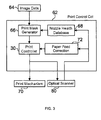
- Fig. 3 is a block diagram of a print control circuit which
controls the operation of the mechanical and electrical
components of the printer of Figure 1.
- Fig. 4 is a flow diagram of a swath height correction routine
implemented by the print control circuit of Fig. 3.
- Fig. 5 is a graph showing the difference between a measured
printed swath height and a nominal swath height.
-
DETAILED DESCRIPTION OF AN EMBODIMENT OF THE INVENTION
-
Referring to Fig. 1, the printer 20 includes a chassis 22
surrounded by a housing 24, together forming a print assembly
portion 26 of the printer 20. The print assembly portion 26
may be supported by a desk or tabletop; however, it is
preferred to support the print assembly portion 26 with a pair
of leg assemblies 28. The printer 20 also has a print
controller 30, illustrated schematically as a microprocessor,
that receives image data from a host device (not shown),
typically a computer, such as a personal computer or a
computer aided drafting (CAD) computer system. The print
controller 30 may also operate in response to user inputs
provided through a key pad and a status display portion 32,
located on the exterior of the housing 24.
-
A conventional paper feed mechanism 60, Fig. 2, is used to
advance a continuous sheet of paper 90 from a roll 34 through
a print zone 35 under the control of the print controller 30.
Alternatively, the printer 20 may be used for printing images
on pre-cut sheets, rather than on paper supplied on a roll 34.
Although referred to herein generically as paper, the print
medium may be any type of suitable sheet material, such as
paper, poster board, fabric, transparencies, mylar, vinyl and
the like. A carriage guide rod 36 is mounted on the chassis
22 to define a scanning axis 38, with the guide rod 36
slidably supporting a carriage 40 for travel back and forth
across the print zone 35. A conventional carriage drive motor
(not shown) is used to propel the carriage 40 under the
control of the print controller 30. The scanning axis 38 is
orthogonal to the direction of paper feed indicated by the
arrow in Fig. 2.
-
To provide carriage positional feedback information to
controller 30, a conventional metallic encoder strip (not
shown) may extend along the length of the print zone 35 and
over a servicing region 42. A conventional optical encoder
reader (not shown) is mounted on the back surface of the
carriage 40 to read positional information provided by the
encoder strip. The manner of providing positional feedback
information via an encoder strip reader is well known to those
skilled in the art.
-
The printer 20 contains four print cartridges 50-56, which are
mounted on the carriage 40 (the cartridge 50 is shown removed
from the carriage in Fig. 1, but in use it will be seated in
the carriage next to the cartridge 52 as shown in Fig. 2). In
the print zone 35, the paper 90 receives ink from the
cartridges 50-56. The cartridges 50-56 are also often called
"pens" by those in the art. One of the pens, for example pen
50, may be configured to eject black ink onto the paper 90,
while pens 52-56 may be configured to eject different coloured
inks such as yellow, magenta and cyan respectively.
-
The printer 20 uses an "off-axis" ink delivery system, having
main stationary reservoirs (not shown) for each ink (black,
yellow, magenta, cyan) located in an ink supply region 74. In
this respect, the term "off-axis" generally refers to a
configuration where the ink supply is separated from the
cartridges 50-56. In this off-axis system, the pens 50-56 are
replenished by ink conveyed through a series of flexible tubes
(not shown) from the main stationary reservoirs so only a
small ink supply is propelled by carriage 40 across the print
zone 35. However, the invention is equally applicable to a
printer wherein each pen contains its own reservoir of ink and
is replaceable as a unit when the ink in the cartridge has run
out.
-
The pens 50-56 have respective printheads 51 which selectively
eject ink to form an image on paper 90 in the print zone 35.
These printheads in this embodiment are quite long, for
instance about 22.5 millimetres long or more, although the
invention may also be applied to shorter printheads. The
printheads each have an orifice plate with a plurality of
nozzles formed therethrough in a manner well known to those
skilled in the art.
-
The nozzles of each printhead are typically formed in an array
of at least one row, but more usually two staggered rows,
along the orifice plate (not shown), the row(s) extending in a
direction orthogonal to the scanning axis 38. The length of
each array determines the nominal image swath height for a
single pass of the printhead.
-
The print controller 30 is arranged to control and coordinate
the operation of the paper feed mechanism 60, the carriage
drive mechanism and the inkjet nozzles of the printheads 50-56
such that a desired image may be built up incrementally swath-by-swath
on the paper 90 in one-pass or multi-pass mode, and
in unidirectional or bi-directional mode, as previously
described, according to the requirements of the job to be
done. For simplicity Fig. 2 shows the printer operating in
one-pass unidirectional mode, the full height of successive
swathes 90-92 being printed during successive right to left
passes of the carriage and (subject to error) placed on the
paper 90 side-by side in non-overlapping abutment.
-
The manner in which the print controller 30 operates is well-known
to those skilled in the art, but will be briefly
described with reference to Fig. 3 which is a schematic block
diagram of a print control circuit 62 of which the print
controller 30 forms part (it will be understood that although
various functional blocks are shown as separate modules in
Fig. 3, in practice these functions are implemented by a
suitably programmed microprocessor and associated memory).
-
Image data 64 is received in a standard format (e.g. tiff) by
the print control circuit 62 from a computer, scanner or other
external device. This data is converted into a print mask by
a print mask generator 66. A print mask is a binary pattern
that determines exactly which ink drops are printed in each
pass by which nozzles. In an N-pass printmode, each pass
should print, of all the ink drops to be printed, a fraction
equal roughly to the reciprocal of N. The print mask is thus
used to "mix up" the nozzles used, as between passes, in such
a way as to reduce undesirable visible printing artefacts.
The print mask generator 66 is responsive to a nozzle health
database 68. The latter stores indications of blocked or
misfiring nozzles, and in generating the print mask the
generator 66 can, in the case of nozzle redundancy, substitute
properly working nozzles for faulty nozzles. This concept and
its implementation are well-known in the art. Finally, the
print mask is used by the print controller 30 to control and
coordinate the operation of the mechanical and electrical
components of the print mechanism 70, that is to say, the
paper feed mechanism 60, the carriage drive mechanism and the
inkjet nozzles of the printheads 50-56.
-
As discussed above, to obtain a high quality image it is
desirable that the paper feed mechanism 60 advance the paper
90 through a distance equal to the height of a swath, or
fraction thereof depending on the printmode, after each pass
of the carriage 40. In this embodiment this is achieved using
an optical scanner 80 which is mounted on the carriage 40
immediately adjacent to the pen 50.
-
In this embodiment the term "optical scanner" means a device
having an array of light sensitive elements ("photodetectors")
each providing a signal whose amplitude is a function of the
amplitude, duration and, where the photodetector is colour-discriminant,
the colour of light falling on it. Such
devices, which are usually based upon photodiodes and charge
coupled devices (CCDs), are well-known in flat bed scanners
and the like which are used to capture images from a printed
media for use in, for example, computing devices; see, for
example US Patent 6,037,584. In the present context, the
terms "light" and "optical" are intended to include
ultraviolet light.
-
The optical scanner 80 is mounted on the carriage 40 in such a
manner that the optical scanner can scan slightly more than
the full height of each right-to-left swath as it is printed.
Clearly the optical scanner is only capable of scanning left-to-right
swaths as they are printed since only in that
direction of movement does the optical scanner trail the
printheads. However, if the scanner were mounted adjacent to
the pen 56 then it would be capable of scanning each left-to-right
swath as it is printed. It is immaterial to the
invention which direction is used. The scanner 80 is arranged
to scan slightly more than the full swath height to ensure
that undesired variations in swath height do not cause the
edges of the swath to fall outside the field of view of the
scanner.
-
In general, in this embodiment, the optical scanner 80 may
comprise any reasonably suitable, commercially available
charge coupled device (CCD) scanner. Although it may be
convenient to mount the scanner to the carriage 40, the
skilled reader will appreciate that in other embodiments this
need not be the case. The optical scanner 80 includes a light
source 82, one or more reflective surfaces 84 (only one
reflective surface is illustrated), a light focusing device
86, and a CCD 88. The optical scanner 80 captures images by
illuminating the images with the light source 82 and sensing
reflected light with the CCD 88. The CCD 88 may be configured
to include various channels (e.g., red, green and blue) to
detect various colours using a single lamp or a one channel
CCD (monochrome) with various colour sources (e.g., light
emitting diodes). A more detailed description of the manner in
which the CCD 88 may operate to detect pixels of an image may
be found in US Patent 6,037,584 referred to above.
-
The optical scanner 80 is operable in this embodiment in
either one of two modes, selected by the print controller 30.
In a first, calibration mode, the scanner is operable to scan
test patterns on the paper 90 to determine the presence and
location of faulty inkjet nozzles, this information being used
to construct the nozzle health database 68. This mode of
operation is the subject of our copending US Patent
Application 09/984937 (HP 60015794-1), the disclosure of which
is incorporated herein by reference, and will not be further
described here. In the second mode of operation, scanned
image data from the optical scanner 80 is input to a paper
feed correction routine 72 in the print control circuit 62 to
adjust the paper feed mechanism to compensate for any
difference between the actual printed swath height and a
nominal swath height. That mode will now be described with
reference primarily to Figs. 4 and 5.
-
As described in US Patent 6,037,584, and in particular Fig. 2
thereof, the optical scanner 80 comprises three rows of
photodiodes sensitive to red, green and blue light
respectively, each row having an associated CCD analog shift
register and the photodiodes in each row being connected via a
transfer gate to respective storage locations in the
associated shift register. Each row of photodiodes has a
resolution greater than the resolution of the printhead
nozzles (i.e. there are more photodiodes per millimetre than
nozzles in the direction orthogonal to the axis 38) and each
row has a field of view extending over slightly more than the
nominal swath height (the nominal swath height is the height
of the right projection of the inkjet nozzles onto the paper).
-
In the second mode, at the start of printing each right-to-left
swath the transfer gates are closed (Step 100) and held
closed for substantially the full length of the swath so that
each photodiode accumulates a charge as the scanner 80 scans
the swath being printed. Since each photodiode only "sees" a
very small fraction of the total height of the swath,
effectively a very narrow line parallel to the swath edges,
the amplitude of the charge accumulated by each photodiode at
the end of the swath is a function of the colour, intensity
and distribution of pixels along the line of the swath scanned
by that photodiode.
-
At the end of printing the swath the transfer gates are opened
so that the charge accumulated on each photodiode is
transferred into the respective storage location of the
associated CCD shift register. In each shift register the
contents of the storage locations are now read out serially,
analog-digital converted, and input to the paper feed
correction routine 72 (Step 102).
-
It will be evident that when the amplitudes of the charges
from any one of the rows of the photodiodes is plotted against
the ordinal number of the photodiode in the row, as seen in
Fig. 5, a graph 200 is produced which is effectively a profile
of the actual printed swath as seen by that row of photodiodes
(in Fig. 5, each point of inflection corresponds to the
amplitude of the accumulated charge on a respective
photodiode). It will also be evident that the print control
circuit 62 "knows" what the nominal swath profile is, i.e.
what the printed profile would be in the absence of errors,
since this can readily be derived from the print mask. The
nominal swath profile 202 corresponding to the actual printed
profile 200 is also shown in Fig. 5. By comparing the two
profiles, the difference between the printed swath height and
the nominal swath height can be calculated, and a scaling
factor passed to the print controller 30 to adjust the amount
by which the paper is advanced to correspond with the actual,
rather than the nominal, swath height. All this is done by
the routine 72.
-
First, therefore, the printed swath profile is calculated
(Step 104). This can be based on the accumulated charges from
just one row of photodiodes, preferably the green-sensitive
row in the case of black text on white paper. Alternatively,
the signals from the three photodiodes in the same ordinal
position in their rows can be added together to give an
amplitude value for each ordinal position of the photodiodes.
The printer control circuit can choose the method most likely
to give a distinctive swath profile for the particular image
concerned.
-
Next a comparison mechanism is selected (Step 106). It will
be recognised that Fig. 5 is a highly idealised graph, and
that in practice few profiles will have such distinctive steps
and edges. In fact, only lines of monochrome text are likely
to show such edges. Also, Fig. 5 shows just a single swath,
and in practice the swath will abut or overlap adjacent
swaths, depending on the printmode, so that distinctive
vertical edges will not necessarily be seen at the trailing
edge of the swath (the leading edge will always be seen since
it is printed on virgin paper). Therefore, the routine 72
selects the most appropriate comparison mechanism. In the
case of a profile having reasonably clear features, a
relatively simple pattern matching algorithm will be
sufficient. In other cases, for example multicolour graphics,
a more sophisticated correlation algorithm would be used.
-
Next the actual comparison is made (Step 108) and from this a
scaling factor for the paper feed mechanism is calculated
(Step 110). As stated, the scaling factor is passed to the
print controller 30 to adjust the amount by which the paper is
advanced to correspond with the actual, rather than the
nominal, swath height. The paper advance may be a full swath
height in the case of one-pass printing, or a fraction of the
swath height in the case of multi-pass printing, but in each
case the full swath height, or the fraction, will be based
upon the actual printed swath height. After Step 110 the
routine loops back to the start in preparation for the next
right-to-left print swath.
-
Due to the position of the optical scanner 80 on the right of
the cartridge 50, Fig. 2, the actual printed swath height
cannot be determined for right-to-left printed swaths.
Therefore, in bi-directional printing the paper feed can be
adjusted only on alternate swaths. However, this is quite
acceptable since significant changes in swath height are not
likely to occur on a swath by swath basis. Indeed, it is
possible to ascertain the actual printed swath height less
often than that; say once every four swaths.
-
Modifications of the above embodiment are possible. For
example, it may not be necessary to optically scan the full
height of the swath provided the part that is chosen provides
a printed swath profile having distinctive features which can
be matched or compared with corresponding features in the
nominal swath profile. This is because Step 110 calculates a
scaling factor, and this can be derived from part only of the
full swath height. However, the part that is chosen
preferably includes the leading edge of the swath, since this
will always give a definite reference point.
-
Also, it is not necessary to accumulate charge along the
entire length of the swath, although in general the greater
the length of the swath which is optically scanned the more
distinctive the profile.
-
Although the foregoing has described embodiments of the
invention in which swath height errors are corrected by
adjusting the amount by which the print medium is advanced
between swaths, other compensation techniques can be used.
For example, the specification of our copending EP Patent
Application No. 03101194.3 (HP 600205021-1), entitled
"Hardcopy apparatus and method", describes an incremental
printer in which the print medium is advanced between
consecutive swaths by a distance slightly less than the height
of the printhead so that in each pass the trailing nozzles of
the printhead pass over the same region of print medium as the
leading nozzles in the previous pass. In such a case banding
between consecutive swaths is mitigated by depletion or
propletion of the number of nozzles used in the overlap
region. The same technique can be used to compensate for
swath height errors in the present invention.
-
The invention is not limited to the embodiment described
herein and may be modified or varied without departing from
the scope of the invention.