EP1130309A1 - Dewatering method for gas supply systems - Google Patents
Dewatering method for gas supply systems Download PDFInfo
- Publication number
- EP1130309A1 EP1130309A1 EP00957104A EP00957104A EP1130309A1 EP 1130309 A1 EP1130309 A1 EP 1130309A1 EP 00957104 A EP00957104 A EP 00957104A EP 00957104 A EP00957104 A EP 00957104A EP 1130309 A1 EP1130309 A1 EP 1130309A1
- Authority
- EP
- European Patent Office
- Prior art keywords
- gas
- flow
- supply system
- moisture
- gas supply
- Prior art date
- Legal status (The legal status is an assumption and is not a legal conclusion. Google has not performed a legal analysis and makes no representation as to the accuracy of the status listed.)
- Granted
Links
- 238000000034 method Methods 0.000 title claims abstract description 39
- XLYOFNOQVPJJNP-UHFFFAOYSA-N water Substances O XLYOFNOQVPJJNP-UHFFFAOYSA-N 0.000 claims abstract description 20
- 229920006395 saturated elastomer Polymers 0.000 claims abstract description 18
- 239000007789 gas Substances 0.000 claims description 254
- 238000011144 upstream manufacturing Methods 0.000 claims description 5
- 239000011261 inert gas Substances 0.000 claims description 3
- 230000001105 regulatory effect Effects 0.000 claims description 2
- 238000010926 purge Methods 0.000 description 49
- 238000012360 testing method Methods 0.000 description 21
- 238000005259 measurement Methods 0.000 description 18
- 238000010586 diagram Methods 0.000 description 12
- 239000012535 impurity Substances 0.000 description 10
- 230000000052 comparative effect Effects 0.000 description 8
- XKRFYHLGVUSROY-UHFFFAOYSA-N Argon Chemical compound [Ar] XKRFYHLGVUSROY-UHFFFAOYSA-N 0.000 description 4
- 238000010276 construction Methods 0.000 description 4
- 238000004519 manufacturing process Methods 0.000 description 4
- 230000007423 decrease Effects 0.000 description 3
- 239000004065 semiconductor Substances 0.000 description 3
- 239000000126 substance Substances 0.000 description 3
- 101100023111 Schizosaccharomyces pombe (strain 972 / ATCC 24843) mfc1 gene Proteins 0.000 description 2
- 229910052786 argon Inorganic materials 0.000 description 2
- 230000001276 controlling effect Effects 0.000 description 2
- 230000000694 effects Effects 0.000 description 2
- 239000012530 fluid Substances 0.000 description 2
- 238000010438 heat treatment Methods 0.000 description 2
- IJGRMHOSHXDMSA-UHFFFAOYSA-N Atomic nitrogen Chemical compound N#N IJGRMHOSHXDMSA-UHFFFAOYSA-N 0.000 description 1
- 238000010521 absorption reaction Methods 0.000 description 1
- 230000002411 adverse Effects 0.000 description 1
- 230000004075 alteration Effects 0.000 description 1
- 238000003795 desorption Methods 0.000 description 1
- 238000009792 diffusion process Methods 0.000 description 1
- 230000005484 gravity Effects 0.000 description 1
- 239000001307 helium Substances 0.000 description 1
- 229910052734 helium Inorganic materials 0.000 description 1
- SWQJXJOGLNCZEY-UHFFFAOYSA-N helium atom Chemical compound [He] SWQJXJOGLNCZEY-UHFFFAOYSA-N 0.000 description 1
- 238000007689 inspection Methods 0.000 description 1
- 239000000463 material Substances 0.000 description 1
- 229910052754 neon Inorganic materials 0.000 description 1
- GKAOGPIIYCISHV-UHFFFAOYSA-N neon atom Chemical compound [Ne] GKAOGPIIYCISHV-UHFFFAOYSA-N 0.000 description 1
- 230000000704 physical effect Effects 0.000 description 1
- 238000003825 pressing Methods 0.000 description 1
- 230000009257 reactivity Effects 0.000 description 1
- 238000012827 research and development Methods 0.000 description 1
- 238000005204 segregation Methods 0.000 description 1
- 239000007787 solid Substances 0.000 description 1
- 238000001179 sorption measurement Methods 0.000 description 1
- 239000000725 suspension Substances 0.000 description 1
- 238000005979 thermal decomposition reaction Methods 0.000 description 1
Images




Classifications
-
- B—PERFORMING OPERATIONS; TRANSPORTING
- B01—PHYSICAL OR CHEMICAL PROCESSES OR APPARATUS IN GENERAL
- B01D—SEPARATION
- B01D53/00—Separation of gases or vapours; Recovering vapours of volatile solvents from gases; Chemical or biological purification of waste gases, e.g. engine exhaust gases, smoke, fumes, flue gases, aerosols
- B01D53/26—Drying gases or vapours
-
- F—MECHANICAL ENGINEERING; LIGHTING; HEATING; WEAPONS; BLASTING
- F17—STORING OR DISTRIBUTING GASES OR LIQUIDS
- F17D—PIPE-LINE SYSTEMS; PIPE-LINES
- F17D3/00—Arrangements for supervising or controlling working operations
- F17D3/14—Arrangements for supervising or controlling working operations for eliminating water
Definitions
- the present invention relates to a method of removing moisture in a gas supply system used in the manufacture of semiconductors, chemicals, precision machine parts and the like. More particularly, the present invention relates to a method of removing moisture in the gas supply system effectively by adjusting the flow pressure of the gas for removing moisture within a specific range without baking (heating) the gas supply system or by intermittently supplying the gas for removing moisture at specific intervals.
- high-purity gases are generally supplied to a gas supply system in semiconductor manufacturing facilities, chemical manufacturing facilities and the like. If semiconductors, chemicals and the like are to be manufactured with high efficiency and purity, it is essential to keep impurities from getting into high-purity gases.
- impurity gases are adsorbed on the inside surface of the piping and other component parts such as various valves and filters.
- the filter in particular is large in adsorption area and the adsorbed impurity molecules are difficult to remove.
- impurity gases adsorbed inside the gas supply system were removed by purging the inside of the gas supply system with a high-purity gas for a long time, or baking the gas supply stem from outside.
- baking is considered to be the most effective way of removing impurity gases.
- Whether the impurity gases have been removed is generally judged in a way that the main components in the evacuated gas are compared before and after the baking.
- the largest impurity gas before baking is H 2 O.
- water decreases drastically as compared with other gases. In other words, moisture is a gas very difficult to remove by evacuation at normal temperature, but is easy to remove by baking.
- baking often has adverse effects on the gas supply system. For example, because of high temperature, materials deteriorate in physical properties. Due to an increase in diffusion coefficient in the solid, segregation, thermal decomposition, or the like, occur. In particular, the gas supply system itself is often so designed that it should not be baked. In such a case, the system cannot be baked.
- An general object of the present invention is to provide a method of removing impurity gases efficiently without baking.
- a first specific object of the present invention is to provide a method of removing moisture in a gas supply system in which adsorbed moisture can be removed effectively by evacuation at normal temperature.
- a second specific object of the present invention is to provide a method of removing moisture in the gas supply system in which adsorbed moisture can be effectively removed by maintaining the flow pressure of the gas for removing moisture within a specific range.
- a third specific object of the present invention is to provide a method of removing moisture in the gas supply system in which adsorbed moisture can be removed efficiently by evacuation at normal temperature even if the gas supply system is a complicated one having valves, filters, pressure regulators, flow regulators, etc.
- a fourth object of the present invention is to provide a method of removing moisture in the gas supply system in which moisture can be removed effectively by evacuation at normal temperature even in a gas supply system of a complicated construction by stopping and allowing, at specific intervals, the flow of the moisture-removing gas without regulating the flow rate of the gas for removing moisture in a meticulous manner.
- the present invention solves the above problems.
- the present invention is to a method of removing remaining moisture in a gas supply system in which the flow pressure of the gas for removing moisture is set at not lower than a minimum pressure where the gas flow becomes a viscous flow and not higher than a water-saturated vapor pressure, which is the basic principle of the present invention.
- a feature of the present invention is that a condition allowing the gas for removing moisture to be a viscous flow is that the mean free path of gas molecules be smaller than the diameter of the piping of the gas supply system.
- the gas supply system from which moisture is removed may be either a gas supply system of a relatively simple construction having filters and valves or one of a relatively complicated construction having filters, pressure regulators, flow regulators, valves, etc.
- the gas supply system may be a gas supply system provided with an evacuation port for the gas for removing moisture at an end of the gas supply system and another on an upstream side of the flow regulator.
- the basic principle of the present invention is a method of removing moisture remaining in the gas supply system by flowing the gas for removing moisture in the gas supply system in which the inside of the gas supply system is evacuated continuously and at the same time the moisture-removing gas to be supplied into the gas supply system is stopped and allowed to flow at specific intervals.
- the supply pressure of the moisture removing gas to be supplied in the gas supply system is brought to between 100-4,500 Torr.
- the flow of the gas for removing moisture in the gas supply system is a viscous flow without fail and the gas pressure in the gas supply system is not higher than the water saturation vapor pressure, thereby facilitating the desorption and removal of the adsorbed water molecules efficiently.
- the desorbed water molecules are driven out by the supply of the gas for removing moisture that follows, and the moisture is removed more efficiently.
- the moisture removing gas from the supply source can be supplied into the gas supply system without adjusting the gas flow rate on a primary side of the gas supply system. This further simplifies the moisture removing process.
- the moisture-removing gas to be supplied into the gas supply system is allowed to flow preferably for 0.9 to 5 seconds and is stopped for 0.3 to 175 seconds alternately. This further improves the moisture-removing efficiency.
- the gas molecules flow, hitting the inside surface of the piping and the complicated inside surface of the filter.
- the inside surface has water molecules sticking to it.
- the gas molecules collide against the water molecules to exchange energy, the water molecules flow and are evacuated by the energy gained.
- the gas molecules also have to be evacuated.
- the collision allows the gas molecules to accelerate and make them flow and be evacuated.
- the gas molecules need to hit water molecules on the inside surface and further collide frequently against each other.
- K L/D (L: mean free path; D: representative length of an object).
- L mean free path
- D representative length of an object
- the representative length D may be a piping diameter.
- L ⁇ D is one of the conditions required in the present invention.
- a fluid in which L ⁇ D is achieved is called a viscous flow.
- d diameter of molecule
- n molecule number density
- the proportional coefficient k is different depending on the kind of gas.
- L 4.98 x 10 -3 /P.
- P 10 -2 (Torr)
- L 0.5 (cm).
- P 10 -1 (Torr)
- L 0.05 (cm).
- the piping diameter D is 0.5 (cm), for example, it is required that L ⁇ D be established if the flow becomes a viscous flow. That is, it is required that the following pressure conditions be met: P ⁇ 10 -2 (Torr). Therefore, the conditions under which the flow becomes a viscous flow mean setting the lowest limit of the gas flow pressure.
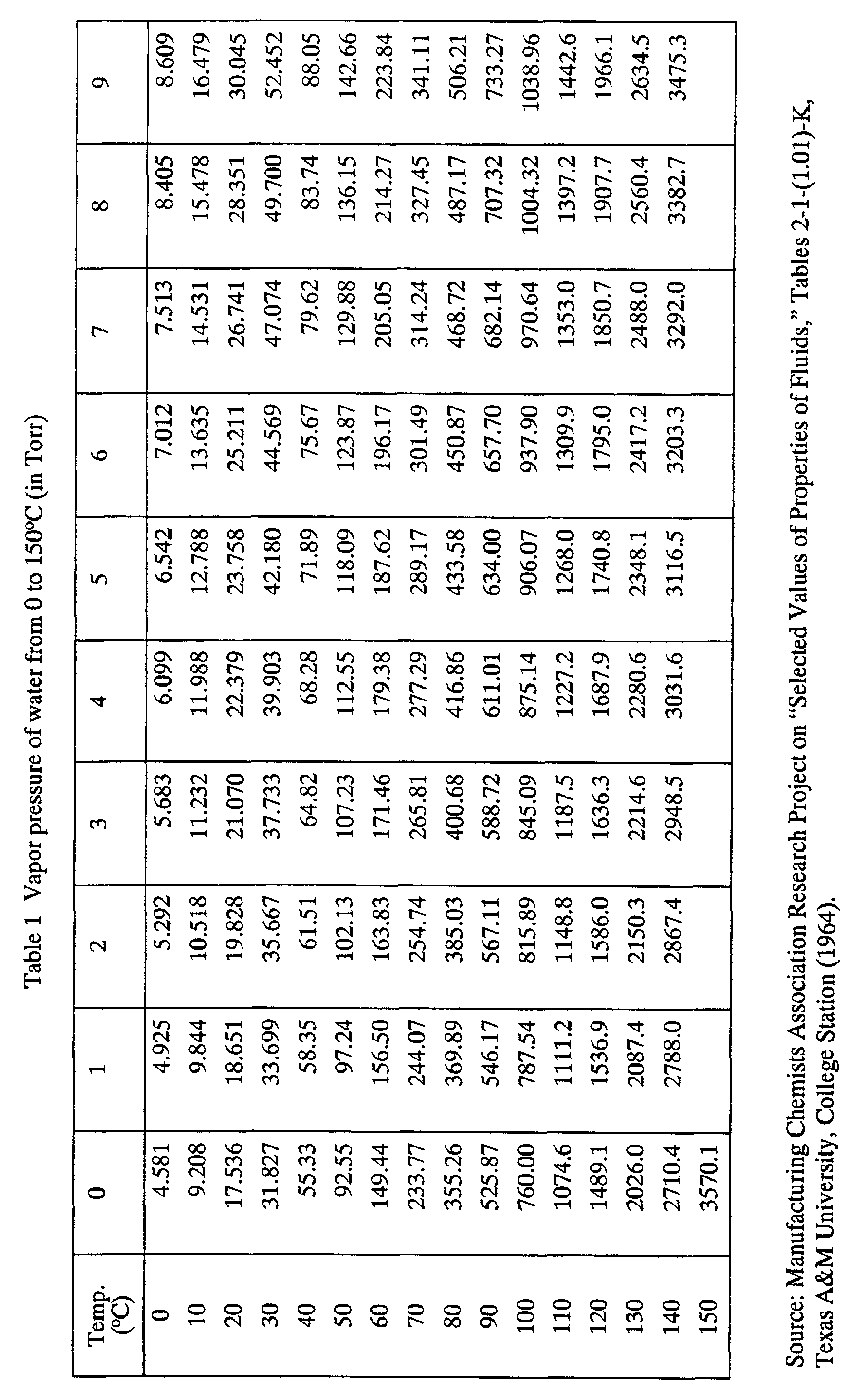
- the highest limit of gas flow pressure P has to be given. It is found that this highest limit condition is the same as the condition under which the moisture adsorbed on the inside surface evaporates within the piping. If the gas flow pressure in the piping is not higher than the saturated vapor pressure Pw of water, moisture could evaporate. Therefore, if P ⁇ Pw, adsorbed moisture can evaporate.
- the saturated vapor pressure Pw of water over a temperature range from 0 to 150°C is shown in Table 1.
- the flow can be made viscous by a dry pump DP, or a vacuum generator VG in which a Venturi tube is utilized. It is easy to achieve a viscous flow, but it is necessary to watch the pressure of the gas flow so that the flow pressure in the piping is made lower than the saturated vapor pressure Pw.
- gases can be used as the gas for removing moisture, including helium (He), neon (Ne), argon (Ar) and nitrogen (N 2 ).
- gases which are low in reactivity and hardly re-adsorb on the gas supply system are the most suitable as the gas for removing moisture.
- FIG. 1 is a schematic diagram of the gas supply system according to the first embodiment.
- Pure argon gas (Ar) is used as the gas for removing moisture.
- the essential point of the present invention is that the flow pressure conditions under which moisture can be removed at 20°C are 10 -2 (Torr) ⁇ P ⁇ 17.5 (Torr).
- the flow becomes a molecular flow.
- P > 17.5 (Torr) the saturated vapor pressure is exceeded and moisture cannot be removed.
- a pressure regulator RG1 reduces Ar gas with a pressure of 4 (kg/cm 2 G) to a desired pressure level and supplies the gas.
- a gas purifier PF removes impurities in the gas.
- Mass flow controllers MFC1, MFC2 and MFC can control the flow rate of the gas flow within any pressure range and flow rate range. Also, a mass flow meter MFM can measure the gas flow rate within a specific range.
- Valves V1 - V14 are used to open and close the gas flow.
- any member can be used but in the present example, a gas filter is used.
- An API-MS is an atmospheric ionized gas mass analyzer and specifies the kinds of components contained in the gas and their specific gravity ratio.
- a valve V9 can be provided with two kinds of vacuum pumps selectively.
- One is a dry pump DP that can evacuate the gas flow pressure to 10 -3 (Torr) and is adjustable to reduce to several hundred Torr by controlling the flow rate of flow from the upstream.
- the other is a Venturi type vacuum generator VG and the attainable pressure is up to 60 (Torr). That is, the pressure adjustable range reached by evacuation is up to 60 (Torr).
- the pressure can be adjusted up to several hundred Torr by controlling the flow rate of flow from the upstream. Therefore, the dry pump DP can cover the molecular flow area, the area of the present invention and the area exceeding the saturated vapor pressure. But the vacuum generator VG can test the area exceeding the saturated vapor pressure only.
- the vacuum generator VG is so constructed that, while the flow rate of N 2 is controlled by the mass flow controller MFC, evacuation is effected.
- the pressure attainable is up to 60 (Torr), as mentioned above.
- the piping of the gas supply system comprises a bypass line BL, a sample line SL, a sample bypass line SBL, a purge line PL and a baking area BA.
- the bypass line BL and sample bypass line SBL are to flow high-purity gas constantly not to raise the background of the analyzer and to flow high-purity gas when the background of the sample line is checked.
- the lines BL and SBL are not for the actual purging. Therefore, the valves V1, V3, V4, V6 and V11 are normally closed.
- the baking area BA While the gas flows, the baking area BA is always heated to 120°C and no adsorbed moisture remains. Moisture generation in the area is prevented. It is also so designed that, when the remaining gas is measured, the moisture is hard to adsorb.
- valves V7, V8, V12, V9 are first closed and the valves V10 and V14 are opened to open the piping. Then, the valve V9 is opened and while the air is sucked, the piping is evacuated for 3 minutes. The valve V10 is then closed to return the piping pressure to atmospheric pressure. This condition is maintained for a specific time to have the same amount of moisture adsorbed in the piping.
- valves V2, V13, V6, V11, V5 are opened while the valves V1, V4 and V12 are closed to flow Ar gas through the sample bypass line SBL at the rate of 1.2 liters/minute to check the background.
- valve 14 is closed and the valves V7, V9 and V10 are opened to allow Ar gas to flow at a specific pressure, whereby the adsorbed moisture in the sample S is removed by the vacuum pump for a specific time.
- the valves V7, V9, V10 are closed and the valves V2, V5, V8, V12, V13 are opened, and the valves V6, V11 are closed to allow Ar gas through the sample line SL at rate of about 1.2 liter/min.
- the baking area BA is heated to 120°C.
- the moisture in the sample S is removed at a specific pressure by the Ar gas purge through the purge line PL in the first stage.
- Ar gas is passed through the sample line SL in the second stage, and while the moisture content is measured by the atmospheric ionized gas mass analyzer API-MS, Ar gas is evacuated. This way, the efficiency of removing moisture by Ar gas purging is measured.
- FIG. 2 is a detailed view of test examples. There are 11 test examples including (1), (4), (5), A - H. Test example (1) is for continuous purge measurement, while the other test samples (4), (5), A - H are for measurements conducted by combining the Ar gas purge in the first stage and allowing the Ar gas to pass through the sample line in the second stage.
- the aforesaid continuous purge measurement is to purge (remove) moisture and to measure the moisture content at the same time.
- the valves V7, V9, V10, V14, V6, V11, V1, V3, V4 are closed, while the valves V2, V13, V12, V8 and V5 are opened.
- Ar gas is flowed through the sample line SL at the rate of 1.2 liter/min.
- the moisture content is measured by the atmospheric ionized gas mass analyzer API-MS.
- Ar gas at room temperature (about 20°C) is flowed at a rate of 1.2 SLM (liter/minute in standard state).
- the batch purge in the test examples (4), (5) is moisture-removing purge in the first stage in which the gas pressure is switched.
- purging with Ar gas under pressure 2 (kgf.cm 2 ) is effected for 5 seconds using the vacuum generator VG and then for another 5 seconds the same way but at pressure 60 (Torr). Alterations between these 5 second purge steps are made (60 times for 10 minutes).
- test examples (4) - H The time given in the parentheses in the test examples (4) - H indicates the time for purging to remove moisture. After these purges, the moisture content is measured.
- the test examples (1), (4) are examples where the saturated vapor pressure of 17.5 (Torr) is exceeded.
- test example (5) a switch is made between the area exceeding the saturation vapor pressure and the molecular flow area.
- Text examples A, B, C, D, E, F, G are in the areas where the flow is a viscous flow and pressure is below the saturated vapor pressure.
- test example H is in the area where the flow is a viscous flow but the pressure exceeds the saturated vapor pressure. That is, there are 7 test examples according to the present invention - A, B, C, D, E, F, G - and the other four examples are comparative examples.
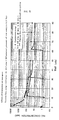
- FIG. 3 is a comparative diagram showing the remaining moisture after various purges. Tests (1), (4), (5) and H are high in startup peak immediately after the start of measurement. It is thus shown that moisture removal by continuous purge and the first stage purge are not sufficient.
- Test (5) is slightly lower than tests (1) and (4) in peak but higher than tests A to G. Specifically, test examples A to G of the present invention are lower than the other comparative examples in peak, showing that the moisture-removing purge in the first stage is effective.
- FIG. 4 is a schematic diagram of a gas supply system according to the second embodiment of the present invention.
- the difference between the schematic diagram of the gas supply system according to the first embodiment shown in FIG. 1 is that (1) the gas supply system is closer to the actual one having a filter FIL, a pressure regulator RG2, a mass flow controller MFC3 and valves for a sample S (surrounded with dotted line in FIG. 4), and (2) evacuation can be effected at two points - on the upstream side of the mass flow controller MFC and at the end of the gas supply system.
- evacuation is effected at two points because the mass flow controller MFC3 for small flow rate is large in resistance in the inside flow path.
- the evacuation may be effected at one point through valve V9a.
- the Ar gas pressure is adjusted to 0.2 MPaG by the pressure regulator RG 1 .
- the valves V7, V8, V12, V9a, V9b are first closed and the valves V14, V15 to V16, V10 are opened to leave the inside of the piping open to the atmosphere. Then, while the valves V9a, V9b are opened to suck the air in, the piping is evacuated. Thereafter, the valve V10 is closed to bring back the pressure inside the piping to atmospheric. This state is maintained for a specific time to let the same amount of moisture adsorb in the sample line SL.
- valves V2, V13, V6, V11, V5 are opened, while the valves V1, V4, V12 are closed to flow the Ar gas to the sample bypass line SBL at the rate of 1.2 liter/min. and to check the background.
- valve V14 is closed, while valves V7, V9a, V9b, V10, V15 to V19 are opened to flow the Ar gas at a specific pressure, whereby the adsorbed moisture in the sample line SL is removed by the vacuum pump for a specific time.
- the valves V7, V9a, V9b, V10 are closed, while valves V2, V5, V8, V12, V13, V15 to V 19 are opened and the valves V6, V11 are closed to flow Ar gas through the sample line SL at the rate of 1.2 liters/min.
- the baking area BA is heated to 120°C.
- the Ar gas is evacuated through the valve V5, the moisture content is measured by the atmospheric ionized gas mass analyzer API-MS. This way, the efficiency of moisture removal by Ar gas purge is measured.
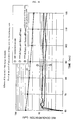
- FIG. 5 shows the remaining moisture content after the Ar gas purge of the gas supply system in FIG. 4.
- the Ar gas purge is carried out with the Ar gas flow rate at 19.7 seem and an internal pressure of the dry pump DP at 14.8 Torr.
- the inside diameter of the piping is 4.4 mm and the pressure of the Ar gas is 14.8 Torr. That is, the aforesaid Ar gas purge is carried out under viscous flow conditions.
- curve b, curve c and curve d indicate measurements of remaining moisture concentrations after the Ar gas purge in the first stage for 10, 30 and 60 minutes.
- the curve a shows the remaining moisture concentration after continuous purging.
- valve V7 is so designed as to continuously open and close in a specific short cycle, and (2) the mass flow controller MFC2 is omitted.
- the reason why the mass flow controller MFC2 is omitted is that there is no need in particular to adjust the flow rate of the Ar gas to be supplied in the first stage Ar gas purge (i.e., purging by supplying the Ar gas intermittently).
- the same amount of moisture is first adsorbed in the piping under the same conditions as in Embodiments 1 and 2.
- Ar gas is flowed through the sample bypass line SBL at the flow rate of 1.2 liters/minute, and the background is checked.
- the dry pump DP is actuated and the valves V7, V9a, V9b, V10, V15, V19 are opened while valves V8, V14, V12 are closed.
- valve V7 is opened and closed in a specific cycle to stop and start the Ar gas supply to the gas supply system, thereby changing the pressure in the sample line SL between tens of Torr (60 Torr, for example) and several Torr (1 Torr, for example).
- the sample line SL is evacuated to a pressure of several Torr.
- the Ar gas flow enters the area of viscous flow and is reduced in pressure to a level lower than the saturated vapor pressure of water.
- the moisture is removed with high efficiency under the same conditions as in Embodiment 1.
- valve V7 If the valve V7 is opened instead, the Ar gas pressure within the sample line SL changes to tens of Torr (60 Torr, for example), getting out of the area of viscous flow. However, a large quantity of Ar gas flowing in when the valve V7 is opened efficiently forces out the water molecules as detached in the sample line SL.
- the pressure, flow rate, etc. of the Ar gas to be supplied to the gas supply system are properly set depending on the constitution of the gas supply system, the capacity of the evacuation unit (dry pump DP) and the inside diameter of the piping path.
- the pressure is usually set at 100 to 4,500 Torr.
- FIG. 6 shows the moisture concentrations remaining after moisture is removed by the third embodiment from the sample line SL of the same construction as that in FIG. 4.
- Curves d, e, f 1 and f 2 are measurements in Embodiment 3.
- the curve d is a measurement of the remaining moisture concentration in the first stage purge conducted so that, while the line is evacuated by the dry pump DP, the Ar gas is flowed for 5 seconds and stopped for 175 sec. This procedure is repeated 60 minutes.
- Curve e is a measurement conducted so that Ar gas is flowed 5 seconds and stopped for 55 seconds. This procedure is repeated for 60 minutes.
- Curve f 1 is a measurement taken this way. The Ar gas is flowed for 5 seconds and stopped for 25 seconds, and this procedure is repeated for 60 minutes.
- the curve f 2 is a measurement conducted so that Ar gas is flowed for 5 seconds and stopped for 25 seconds, and this procedure is repeated for 360 minutes.
- the curve a is a measurement taken with the line continuously purged with the Ar gas under identical conditions as the curve (1) in FIG. 3 in Embodiment 1 and the curve a in FIG. 5 in Embodiment 2.
- the curve b in FIG. 6 is a measurement taken this way.
- a procedure comprising applying pressure with the Ar gas at 2 kf/cm 2 for 10 seconds and evacuation by the vacuum generator VG for 30 seconds (about 70 Torr) is repeated for 30 minutes (batch procedure).
- the curves C 1 - C 4 in FIG. 6 show remaining moisture concentrations measured the same way as in FIG. 5 in Embodiment 2. That is, the first stage purge is conducted for 30, 60, 180 and 360 minutes under the conditions that the Ar gas flow rate is 19.7 sccs at a pressure of 14.8 Torr (a viscous flow purge).
- FIG. 7 shows changes in moisture removing efficiency observed when the number of the opening and closing cycles of the valve 7 is varied in Embodiment 3.
- Curves (2) to (6) in FIG. 7 show measurements in remaining moisture concentration in the Ar gas in Embodiment 3.
- Curve (1) which is shown for comparison, shows a measurement of remaining moisture concentration within the Ar gas in case of continuous gas purge.
- the curve (2) in FIG. 7, for example, is a measurement taken this way. With evacuation being conducted, the Ar gas is flowed for 0.9 seconds and stopped for 0.3 seconds. This procedure is repeated 3,000 times (for 60 minutes). After that, the moisture concentration in the Ar gas is measured continuously for 30 minutes.
- FIG. 8 compares the moisture removing efficiencies in Embodiment 3 of the present invention between the following cases: one where the flow rate of the Ar gas is so adjusted that the Ar gas supplied from the primary side becomes a viscous flow and the other case where the Ar gas is supplied to the sample line SL at the original flow rate initially adjusted on the supply source side with no adjustment made to the flow rate of the Ar gas for purge to be sent to the sample line SL (that is, without the mass flow controller MFC 2 in FIG. 4 provided).
- the gas supply systems according to the Embodiments 1 and 2 shown in FIGS. 1 and 4 are provided with the bypass line BL and the sample bypass line SBL.
- the bypass line BL and the sample bypass line SBL can be omitted.
- the flow pressure of the gas for removing moisture is set at not lower than the lowest pressure at which the flow becomes a viscous flow and not higher than the saturated vapor pressure. Therefore, the collision of gas molecules can effectively remove moisture adsorbed on the inside surface of the gas supply system. Thus, an effective method of removing moisture without baking is established, especially for a part that should not be baked.
- conditions for forming viscous flow are achieved by making the mean free path of gas molecules smaller than the piping diameter. Therefore, the minimum pressure that satisfies the conditions for viscous flow can be derived without difficulty.
- inert gases such as Ar gas are selected as gas for removing moisture. Therefore, after moisture molecules are forced out, the gas itself will hardly be adsorbed in the supply system.
- moisture inside the sample line can be removed efficiently whether the sample line is formed of such simple parts as a filter or a complicated piping system path having a filter, pressure regulator, mass flow controller and control valve.
- moisture can be removed efficiently from a more complicated gas system without adjusting with high precision the flow rate of the gas for removing moisture supplied from the primary side. Moisture can be removed in a short time, simply and easily.
- moisture can be removed efficiently in a still shorter time by increasing the number of cycles of stopping the flow of the gas removing moisture and allowing the gas to flow.
- the present invention is excellent in practicability.
- the present invention is not limited to the embodiments and examples described above, and it is to be understood that changes and variations may be made without departing from the spirit or scope of the present invention.
Landscapes
- Engineering & Computer Science (AREA)
- Chemical & Material Sciences (AREA)
- Mechanical Engineering (AREA)
- General Engineering & Computer Science (AREA)
- Analytical Chemistry (AREA)
- General Chemical & Material Sciences (AREA)
- Oil, Petroleum & Natural Gas (AREA)
- Chemical Kinetics & Catalysis (AREA)
- Drying Of Gases (AREA)
- Pipeline Systems (AREA)
Abstract
Description
- RG1
- pressure regulator
- PF
- gas purifier
- MFC1
- mass flow controller
- MFC2
- mass flow controller
- MFC3
- mass flow controller
- MFC4
- mass flow controller
- MFM
- mass flow meter
- V1 - V19
- valves
- API-MS
- atmospheric ionized gas mass analyzer
- DP
- dry pump
- VG
- vacuum generator
- BL
- bypass line
- SL
- sample line
- SBL
- sample bypass line
- PL
- purge line
- BA
- baking area
- SLM
- liter/minute in a standard state
- vac
- evacuation
- seem
- cm3/minute in a standard state
- sccs
- cm3/second in a standard state
Claims (11)
- A method of removing moisture remaining in a gas supply system having piping, comprising the steps of:flowing a gas to remove moisture in the gas supply system at a flow pressure; andsetting the flow pressure of the gas to remove moisture at a level not lower than the lowest pressure at which gas flow becomes viscous flow and not higher than a saturated vapor pressure of water at a flow temperature of the gas for removing moisture.
- A method as defined in claim 1, wherein, in said viscous flow, a mean free path of the gas to remove moisture is smaller than a diameter of the piping of the gas supply system.
- A method as defined in claim 1, wherein said gas to remove moisture is an inert gas.
- A method as defined in claim 1, wherein said gas supply system comprises a filter and valves.
- A method as defined in claim 1, wherein said gas supply system comprises a filter, pressure regulator, flow rate regulator and valves.
- A method as defined in claim 1, wherein the gas supply system has an evacuating port for the gas to remove moisture, and a flow rate regulator, and wherein evacuation is effectable at an end of the gas supply system and on an upstream side of the flow rate regulator.
- A method of removing moisture remaining in a gas supply system having an inside, comprising the steps of:flowing a gas to remove moisture in the gas supply system;alternately stopping the flow the gas to remove moisture at specific intervals; andcontinuously evacuating the inside of the gas supply system during the steps of flowing and alternately stopping.
- A method as defined in claim 7, wherein, during the step of alternately stopping, a flow pressure of the gas to remove moisture inside the gas supply system is brought, by said step of continuously evacuating to a pressure level between a minimum pressure where the gas flow becomes viscous flow and a saturated vapor pressure of water at a flow temperature of the gas to remove moisture.
- A method as defined in claim 7, further comprising the step of supplying the gas to remove moisture into the gas supply system between about 100 to 4,500 Torr.
- A method as defined in claim 7, further comprising the step of supplying the gas to remove moisture to the gas supply system without regulating gas flow on a primary side of the gas supply system.
- A method as defined in claim 7, wherein the steps of flowing and alternately stopping comprise, flowing for a time between about 0.9 to 5 seconds and alternately stopping the flow between about 0.3 to 175 seconds.
Applications Claiming Priority (3)
| Application Number | Priority Date | Filing Date | Title |
|---|---|---|---|
| JP25854799 | 1999-09-13 | ||
| JP25854799 | 1999-09-13 | ||
| PCT/JP2000/006209 WO2001020221A1 (en) | 1999-09-13 | 2000-09-11 | Dewatering method for gas supply systems |
Publications (3)
| Publication Number | Publication Date |
|---|---|
| EP1130309A1 true EP1130309A1 (en) | 2001-09-05 |
| EP1130309A4 EP1130309A4 (en) | 2005-07-06 |
| EP1130309B1 EP1130309B1 (en) | 2006-07-26 |
Family
ID=17321757
Family Applications (1)
| Application Number | Title | Priority Date | Filing Date |
|---|---|---|---|
| EP00957104A Expired - Lifetime EP1130309B1 (en) | 1999-09-13 | 2000-09-11 | Dewatering method for gas supply systems |
Country Status (8)
| Country | Link |
|---|---|
| US (1) | US6387158B2 (en) |
| EP (1) | EP1130309B1 (en) |
| KR (1) | KR100427565B1 (en) |
| CN (1) | CN1114059C (en) |
| CA (1) | CA2347784A1 (en) |
| DE (1) | DE60029557D1 (en) |
| IL (1) | IL142646A0 (en) |
| WO (1) | WO2001020221A1 (en) |
Families Citing this family (6)
| Publication number | Priority date | Publication date | Assignee | Title |
|---|---|---|---|---|
| EP1651093B1 (en) * | 2003-07-30 | 2016-09-07 | BSH Hausgeräte GmbH | Method for operating a dishwasher with at least one partial programme step of drying |
| CN102141195A (en) * | 2011-01-13 | 2011-08-03 | 天津市益斯达燃气设备有限公司 | Miniature compressed natural gas decompression gas-supply system |
| US9454158B2 (en) | 2013-03-15 | 2016-09-27 | Bhushan Somani | Real time diagnostics for flow controller systems and methods |
| US10983538B2 (en) | 2017-02-27 | 2021-04-20 | Flow Devices And Systems Inc. | Systems and methods for flow sensor back pressure adjustment for mass flow controller |
| CN114468753B (en) * | 2020-11-11 | 2023-06-02 | 佛山市顺德区美的电热电器制造有限公司 | Waterless baking cooking method of cooking utensil and cooking utensil |
| CN115920586A (en) * | 2022-12-22 | 2023-04-07 | 中触媒新材料股份有限公司 | A method for removing water by pressure swing adsorption |
Family Cites Families (8)
| Publication number | Priority date | Publication date | Assignee | Title |
|---|---|---|---|---|
| US3800507A (en) * | 1970-06-23 | 1974-04-02 | Us Navy | Low pressure air dehydrator |
| DE2724763C2 (en) * | 1977-06-01 | 1984-02-16 | Linde Ag, 6200 Wiesbaden | Process for cleaning and decomposing a gas mixture |
| US4351732A (en) * | 1980-12-12 | 1982-09-28 | The C. M. Kemp Manufacturing Co. | Dehydration of ethanol |
| US4711645A (en) * | 1986-02-10 | 1987-12-08 | Air Products And Chemicals, Inc. | Removal of water and carbon dioxide from atmospheric air |
| US4961759A (en) * | 1989-08-17 | 1990-10-09 | Separation Dynamics, Inc. | Closed loop gas dehydration process and apparatus |
| CN1027802C (en) * | 1990-01-19 | 1995-03-08 | 波克集团股份有限公司 | Low temp. purification of gases |
| JPH07312344A (en) * | 1994-05-17 | 1995-11-28 | Mitsubishi Electric Corp | Semiconductor manufacturing equipment |
| JP3323781B2 (en) * | 1996-09-05 | 2002-09-09 | 日揮株式会社 | Gas transfer piping |
-
2000
- 2000-09-11 KR KR10-2001-7002238A patent/KR100427565B1/en not_active Expired - Fee Related
- 2000-09-11 WO PCT/JP2000/006209 patent/WO2001020221A1/en not_active Ceased
- 2000-09-11 DE DE60029557T patent/DE60029557D1/en not_active Expired - Lifetime
- 2000-09-11 EP EP00957104A patent/EP1130309B1/en not_active Expired - Lifetime
- 2000-09-11 CN CN00801268A patent/CN1114059C/en not_active Expired - Fee Related
- 2000-09-11 CA CA002347784A patent/CA2347784A1/en not_active Abandoned
- 2000-09-11 IL IL14264600A patent/IL142646A0/en not_active IP Right Cessation
-
2001
- 2001-05-04 US US09/848,208 patent/US6387158B2/en not_active Expired - Fee Related
Also Published As
| Publication number | Publication date |
|---|---|
| DE60029557D1 (en) | 2006-09-07 |
| KR20010072844A (en) | 2001-07-31 |
| EP1130309B1 (en) | 2006-07-26 |
| KR100427565B1 (en) | 2004-04-28 |
| CN1114059C (en) | 2003-07-09 |
| US6387158B2 (en) | 2002-05-14 |
| EP1130309A4 (en) | 2005-07-06 |
| WO2001020221A1 (en) | 2001-03-22 |
| CN1316044A (en) | 2001-10-03 |
| US20020000161A1 (en) | 2002-01-03 |
| IL142646A0 (en) | 2002-03-10 |
| CA2347784A1 (en) | 2001-03-22 |
Similar Documents
| Publication | Publication Date | Title |
|---|---|---|
| US7793685B2 (en) | Controlling gas partial pressures for process optimization | |
| KR101140476B1 (en) | Treating-gas supply system and treating apparatus | |
| TWI681437B (en) | Systems and methods for treating substrates with cryogenic fluid mixtures | |
| JP3332053B2 (en) | Gas supply method to chamber | |
| JP4365785B2 (en) | Deposition equipment | |
| US20050109419A1 (en) | Gas supplying method and system | |
| US10957554B2 (en) | Etching method and etching device | |
| EP1130309B1 (en) | Dewatering method for gas supply systems | |
| JPH02284638A (en) | Feeder of high-performance process gas | |
| CN114050100B (en) | Plasma processing system and plasma processing method | |
| CN109764584B (en) | Low-pressure refrigeration system | |
| US4621985A (en) | High vacuum apparatus | |
| EP0877246A2 (en) | In situ monitoring of contaminants in semiconductor processing chambers | |
| CN100458629C (en) | Fluid treatment device and fluid treatment method | |
| JP3387898B2 (en) | How to remove moisture from gas supply system | |
| JP7682935B2 (en) | Supply method and supply device | |
| JP3291369B2 (en) | Treatment method of exhaust gas containing organic vapor | |
| JPH0729962A (en) | Vacuum exhaust method and device | |
| JP4933414B2 (en) | Compound thin film semiconductor manufacturing apparatus and ammonia gas supply apparatus and method | |
| JP2507518B2 (en) | Vacuum exhaust device | |
| JPH03106432A (en) | Degassing method and degassing device for vacuum equipment | |
| KR20220046675A (en) | Method for manufacturing passivation film | |
| CN112530777B (en) | Air extraction device and air extraction method thereof | |
| JPS6314866A (en) | Device for supplying ultra-high-purity gas | |
| WO2005061758A1 (en) | Transfer system |
Legal Events
| Date | Code | Title | Description |
|---|---|---|---|
| PUAI | Public reference made under article 153(3) epc to a published international application that has entered the european phase |
Free format text: ORIGINAL CODE: 0009012 |
|
| 17P | Request for examination filed |
Effective date: 20010414 |
|
| AK | Designated contracting states |
Kind code of ref document: A1 Designated state(s): CH DE FR GB IT LI NL |
|
| RIC1 | Information provided on ipc code assigned before grant |
Ipc: 7B 01D 53/26 B Ipc: 7F 17D 1/04 A Ipc: 7F 17D 3/14 B |
|
| A4 | Supplementary search report drawn up and despatched |
Effective date: 20050523 |
|
| GRAP | Despatch of communication of intention to grant a patent |
Free format text: ORIGINAL CODE: EPIDOSNIGR1 |
|
| GRAS | Grant fee paid |
Free format text: ORIGINAL CODE: EPIDOSNIGR3 |
|
| GRAA | (expected) grant |
Free format text: ORIGINAL CODE: 0009210 |
|
| AK | Designated contracting states |
Kind code of ref document: B1 Designated state(s): CH DE FR GB IT LI NL |
|
| PG25 | Lapsed in a contracting state [announced via postgrant information from national office to epo] |
Ref country code: IT Free format text: LAPSE BECAUSE OF FAILURE TO SUBMIT A TRANSLATION OF THE DESCRIPTION OR TO PAY THE FEE WITHIN THE PRESCRIBED TIME-LIMIT;WARNING: LAPSES OF ITALIAN PATENTS WITH EFFECTIVE DATE BEFORE 2007 MAY HAVE OCCURRED AT ANY TIME BEFORE 2007. THE CORRECT EFFECTIVE DATE MAY BE DIFFERENT FROM THE ONE RECORDED. Effective date: 20060726 Ref country code: NL Free format text: LAPSE BECAUSE OF FAILURE TO SUBMIT A TRANSLATION OF THE DESCRIPTION OR TO PAY THE FEE WITHIN THE PRESCRIBED TIME-LIMIT Effective date: 20060726 Ref country code: LI Free format text: LAPSE BECAUSE OF FAILURE TO SUBMIT A TRANSLATION OF THE DESCRIPTION OR TO PAY THE FEE WITHIN THE PRESCRIBED TIME-LIMIT Effective date: 20060726 Ref country code: CH Free format text: LAPSE BECAUSE OF FAILURE TO SUBMIT A TRANSLATION OF THE DESCRIPTION OR TO PAY THE FEE WITHIN THE PRESCRIBED TIME-LIMIT Effective date: 20060726 |
|
| REG | Reference to a national code |
Ref country code: GB Ref legal event code: FG4D |
|
| REG | Reference to a national code |
Ref country code: CH Ref legal event code: EP |
|
| REF | Corresponds to: |
Ref document number: 60029557 Country of ref document: DE Date of ref document: 20060907 Kind code of ref document: P |
|
| PG25 | Lapsed in a contracting state [announced via postgrant information from national office to epo] |
Ref country code: DE Free format text: LAPSE BECAUSE OF FAILURE TO SUBMIT A TRANSLATION OF THE DESCRIPTION OR TO PAY THE FEE WITHIN THE PRESCRIBED TIME-LIMIT Effective date: 20061027 |
|
| NLV1 | Nl: lapsed or annulled due to failure to fulfill the requirements of art. 29p and 29m of the patents act | ||
| EN | Fr: translation not filed | ||
| PLBE | No opposition filed within time limit |
Free format text: ORIGINAL CODE: 0009261 |
|
| STAA | Information on the status of an ep patent application or granted ep patent |
Free format text: STATUS: NO OPPOSITION FILED WITHIN TIME LIMIT |
|
| GBPC | Gb: european patent ceased through non-payment of renewal fee |
Effective date: 20061026 |
|
| 26N | No opposition filed |
Effective date: 20070427 |
|
| PG25 | Lapsed in a contracting state [announced via postgrant information from national office to epo] |
Ref country code: GB Free format text: LAPSE BECAUSE OF NON-PAYMENT OF DUE FEES Effective date: 20061026 |
|
| PG25 | Lapsed in a contracting state [announced via postgrant information from national office to epo] |
Ref country code: FR Free format text: LAPSE BECAUSE OF FAILURE TO SUBMIT A TRANSLATION OF THE DESCRIPTION OR TO PAY THE FEE WITHIN THE PRESCRIBED TIME-LIMIT Effective date: 20070511 |
|
| PG25 | Lapsed in a contracting state [announced via postgrant information from national office to epo] |
Ref country code: FR Free format text: LAPSE BECAUSE OF FAILURE TO SUBMIT A TRANSLATION OF THE DESCRIPTION OR TO PAY THE FEE WITHIN THE PRESCRIBED TIME-LIMIT Effective date: 20060726 |