EP1130303A1 - Composite high-pressure pipe and method of joining same - Google Patents
Composite high-pressure pipe and method of joining same Download PDFInfo
- Publication number
- EP1130303A1 EP1130303A1 EP99944830A EP99944830A EP1130303A1 EP 1130303 A1 EP1130303 A1 EP 1130303A1 EP 99944830 A EP99944830 A EP 99944830A EP 99944830 A EP99944830 A EP 99944830A EP 1130303 A1 EP1130303 A1 EP 1130303A1
- Authority
- EP
- European Patent Office
- Prior art keywords
- pipe
- pressure composite
- layer
- reinforcing layer
- reinforcing
- Prior art date
- Legal status (The legal status is an assumption and is not a legal conclusion. Google has not performed a legal analysis and makes no representation as to the accuracy of the status listed.)
- Granted
Links
Images














Classifications
-
- B—PERFORMING OPERATIONS; TRANSPORTING
- B32—LAYERED PRODUCTS
- B32B—LAYERED PRODUCTS, i.e. PRODUCTS BUILT-UP OF STRATA OF FLAT OR NON-FLAT, e.g. CELLULAR OR HONEYCOMB, FORM
- B32B1/00—Layered products having a non-planar shape
- B32B1/08—Tubular products
-
- B—PERFORMING OPERATIONS; TRANSPORTING
- B29—WORKING OF PLASTICS; WORKING OF SUBSTANCES IN A PLASTIC STATE IN GENERAL
- B29C—SHAPING OR JOINING OF PLASTICS; SHAPING OF MATERIAL IN A PLASTIC STATE, NOT OTHERWISE PROVIDED FOR; AFTER-TREATMENT OF THE SHAPED PRODUCTS, e.g. REPAIRING
- B29C65/00—Joining or sealing of preformed parts, e.g. welding of plastics materials; Apparatus therefor
- B29C65/02—Joining or sealing of preformed parts, e.g. welding of plastics materials; Apparatus therefor by heating, with or without pressure
- B29C65/18—Joining or sealing of preformed parts, e.g. welding of plastics materials; Apparatus therefor by heating, with or without pressure using heated tools
- B29C65/20—Joining or sealing of preformed parts, e.g. welding of plastics materials; Apparatus therefor by heating, with or without pressure using heated tools with direct contact, e.g. using "mirror"
-
- B—PERFORMING OPERATIONS; TRANSPORTING
- B29—WORKING OF PLASTICS; WORKING OF SUBSTANCES IN A PLASTIC STATE IN GENERAL
- B29C—SHAPING OR JOINING OF PLASTICS; SHAPING OF MATERIAL IN A PLASTIC STATE, NOT OTHERWISE PROVIDED FOR; AFTER-TREATMENT OF THE SHAPED PRODUCTS, e.g. REPAIRING
- B29C65/00—Joining or sealing of preformed parts, e.g. welding of plastics materials; Apparatus therefor
- B29C65/56—Joining or sealing of preformed parts, e.g. welding of plastics materials; Apparatus therefor using mechanical means or mechanical connections, e.g. form-fits
-
- B—PERFORMING OPERATIONS; TRANSPORTING
- B29—WORKING OF PLASTICS; WORKING OF SUBSTANCES IN A PLASTIC STATE IN GENERAL
- B29C—SHAPING OR JOINING OF PLASTICS; SHAPING OF MATERIAL IN A PLASTIC STATE, NOT OTHERWISE PROVIDED FOR; AFTER-TREATMENT OF THE SHAPED PRODUCTS, e.g. REPAIRING
- B29C65/00—Joining or sealing of preformed parts, e.g. welding of plastics materials; Apparatus therefor
- B29C65/56—Joining or sealing of preformed parts, e.g. welding of plastics materials; Apparatus therefor using mechanical means or mechanical connections, e.g. form-fits
- B29C65/562—Joining or sealing of preformed parts, e.g. welding of plastics materials; Apparatus therefor using mechanical means or mechanical connections, e.g. form-fits using extra joining elements, i.e. which are not integral with the parts to be joined
-
- B—PERFORMING OPERATIONS; TRANSPORTING
- B29—WORKING OF PLASTICS; WORKING OF SUBSTANCES IN A PLASTIC STATE IN GENERAL
- B29C—SHAPING OR JOINING OF PLASTICS; SHAPING OF MATERIAL IN A PLASTIC STATE, NOT OTHERWISE PROVIDED FOR; AFTER-TREATMENT OF THE SHAPED PRODUCTS, e.g. REPAIRING
- B29C65/00—Joining or sealing of preformed parts, e.g. welding of plastics materials; Apparatus therefor
- B29C65/56—Joining or sealing of preformed parts, e.g. welding of plastics materials; Apparatus therefor using mechanical means or mechanical connections, e.g. form-fits
- B29C65/567—Joining or sealing of preformed parts, e.g. welding of plastics materials; Apparatus therefor using mechanical means or mechanical connections, e.g. form-fits using a tamping or a swaging operation, i.e. at least partially deforming the edge or the rim of a first part to be joined to clamp a second part to be joined
- B29C65/568—Joining or sealing of preformed parts, e.g. welding of plastics materials; Apparatus therefor using mechanical means or mechanical connections, e.g. form-fits using a tamping or a swaging operation, i.e. at least partially deforming the edge or the rim of a first part to be joined to clamp a second part to be joined using a swaging operation, i.e. totally deforming the edge or the rim of a first part to be joined to clamp a second part to be joined
-
- B—PERFORMING OPERATIONS; TRANSPORTING
- B29—WORKING OF PLASTICS; WORKING OF SUBSTANCES IN A PLASTIC STATE IN GENERAL
- B29C—SHAPING OR JOINING OF PLASTICS; SHAPING OF MATERIAL IN A PLASTIC STATE, NOT OTHERWISE PROVIDED FOR; AFTER-TREATMENT OF THE SHAPED PRODUCTS, e.g. REPAIRING
- B29C65/00—Joining or sealing of preformed parts, e.g. welding of plastics materials; Apparatus therefor
- B29C65/66—Joining or sealing of preformed parts, e.g. welding of plastics materials; Apparatus therefor by liberation of internal stresses, e.g. shrinking of one of the parts to be joined
- B29C65/68—Joining or sealing of preformed parts, e.g. welding of plastics materials; Apparatus therefor by liberation of internal stresses, e.g. shrinking of one of the parts to be joined using auxiliary shrinkable elements
-
- B—PERFORMING OPERATIONS; TRANSPORTING
- B29—WORKING OF PLASTICS; WORKING OF SUBSTANCES IN A PLASTIC STATE IN GENERAL
- B29C—SHAPING OR JOINING OF PLASTICS; SHAPING OF MATERIAL IN A PLASTIC STATE, NOT OTHERWISE PROVIDED FOR; AFTER-TREATMENT OF THE SHAPED PRODUCTS, e.g. REPAIRING
- B29C65/00—Joining or sealing of preformed parts, e.g. welding of plastics materials; Apparatus therefor
- B29C65/82—Testing the joint
- B29C65/8207—Testing the joint by mechanical methods
- B29C65/823—Bend tests
-
- B—PERFORMING OPERATIONS; TRANSPORTING
- B29—WORKING OF PLASTICS; WORKING OF SUBSTANCES IN A PLASTIC STATE IN GENERAL
- B29C—SHAPING OR JOINING OF PLASTICS; SHAPING OF MATERIAL IN A PLASTIC STATE, NOT OTHERWISE PROVIDED FOR; AFTER-TREATMENT OF THE SHAPED PRODUCTS, e.g. REPAIRING
- B29C65/00—Joining or sealing of preformed parts, e.g. welding of plastics materials; Apparatus therefor
- B29C65/82—Testing the joint
- B29C65/8207—Testing the joint by mechanical methods
- B29C65/8246—Pressure tests, e.g. hydrostatic pressure tests
-
- B—PERFORMING OPERATIONS; TRANSPORTING
- B29—WORKING OF PLASTICS; WORKING OF SUBSTANCES IN A PLASTIC STATE IN GENERAL
- B29C—SHAPING OR JOINING OF PLASTICS; SHAPING OF MATERIAL IN A PLASTIC STATE, NOT OTHERWISE PROVIDED FOR; AFTER-TREATMENT OF THE SHAPED PRODUCTS, e.g. REPAIRING
- B29C66/00—General aspects of processes or apparatus for joining preformed parts
- B29C66/01—General aspects dealing with the joint area or with the area to be joined
- B29C66/03—After-treatments in the joint area
- B29C66/038—Covering the joint by a coating material
-
- B—PERFORMING OPERATIONS; TRANSPORTING
- B29—WORKING OF PLASTICS; WORKING OF SUBSTANCES IN A PLASTIC STATE IN GENERAL
- B29C—SHAPING OR JOINING OF PLASTICS; SHAPING OF MATERIAL IN A PLASTIC STATE, NOT OTHERWISE PROVIDED FOR; AFTER-TREATMENT OF THE SHAPED PRODUCTS, e.g. REPAIRING
- B29C66/00—General aspects of processes or apparatus for joining preformed parts
- B29C66/01—General aspects dealing with the joint area or with the area to be joined
- B29C66/05—Particular design of joint configurations
- B29C66/10—Particular design of joint configurations particular design of the joint cross-sections
- B29C66/11—Joint cross-sections comprising a single joint-segment, i.e. one of the parts to be joined comprising a single joint-segment in the joint cross-section
- B29C66/114—Single butt joints
- B29C66/1142—Single butt to butt joints
-
- B—PERFORMING OPERATIONS; TRANSPORTING
- B29—WORKING OF PLASTICS; WORKING OF SUBSTANCES IN A PLASTIC STATE IN GENERAL
- B29C—SHAPING OR JOINING OF PLASTICS; SHAPING OF MATERIAL IN A PLASTIC STATE, NOT OTHERWISE PROVIDED FOR; AFTER-TREATMENT OF THE SHAPED PRODUCTS, e.g. REPAIRING
- B29C66/00—General aspects of processes or apparatus for joining preformed parts
- B29C66/01—General aspects dealing with the joint area or with the area to be joined
- B29C66/32—Measures for keeping the burr form under control; Avoiding burr formation; Shaping the burr
- B29C66/328—Leaving the burrs unchanged for providing particular properties to the joint, e.g. as decorative effect
- B29C66/3282—Leaving the burrs unchanged for providing particular properties to the joint, e.g. as decorative effect for reinforcing the joint
-
- B—PERFORMING OPERATIONS; TRANSPORTING
- B29—WORKING OF PLASTICS; WORKING OF SUBSTANCES IN A PLASTIC STATE IN GENERAL
- B29C—SHAPING OR JOINING OF PLASTICS; SHAPING OF MATERIAL IN A PLASTIC STATE, NOT OTHERWISE PROVIDED FOR; AFTER-TREATMENT OF THE SHAPED PRODUCTS, e.g. REPAIRING
- B29C66/00—General aspects of processes or apparatus for joining preformed parts
- B29C66/50—General aspects of joining tubular articles; General aspects of joining long products, i.e. bars or profiled elements; General aspects of joining single elements to tubular articles, hollow articles or bars; General aspects of joining several hollow-preforms to form hollow or tubular articles
- B29C66/51—Joining tubular articles, profiled elements or bars; Joining single elements to tubular articles, hollow articles or bars; Joining several hollow-preforms to form hollow or tubular articles
- B29C66/52—Joining tubular articles, bars or profiled elements
- B29C66/522—Joining tubular articles
- B29C66/5221—Joining tubular articles for forming coaxial connections, i.e. the tubular articles to be joined forming a zero angle relative to each other
-
- B—PERFORMING OPERATIONS; TRANSPORTING
- B29—WORKING OF PLASTICS; WORKING OF SUBSTANCES IN A PLASTIC STATE IN GENERAL
- B29C—SHAPING OR JOINING OF PLASTICS; SHAPING OF MATERIAL IN A PLASTIC STATE, NOT OTHERWISE PROVIDED FOR; AFTER-TREATMENT OF THE SHAPED PRODUCTS, e.g. REPAIRING
- B29C66/00—General aspects of processes or apparatus for joining preformed parts
- B29C66/70—General aspects of processes or apparatus for joining preformed parts characterised by the composition, physical properties or the structure of the material of the parts to be joined; Joining with non-plastics material
- B29C66/72—General aspects of processes or apparatus for joining preformed parts characterised by the composition, physical properties or the structure of the material of the parts to be joined; Joining with non-plastics material characterised by the structure of the material of the parts to be joined
- B29C66/723—General aspects of processes or apparatus for joining preformed parts characterised by the composition, physical properties or the structure of the material of the parts to be joined; Joining with non-plastics material characterised by the structure of the material of the parts to be joined being multi-layered
-
- B—PERFORMING OPERATIONS; TRANSPORTING
- B29—WORKING OF PLASTICS; WORKING OF SUBSTANCES IN A PLASTIC STATE IN GENERAL
- B29C—SHAPING OR JOINING OF PLASTICS; SHAPING OF MATERIAL IN A PLASTIC STATE, NOT OTHERWISE PROVIDED FOR; AFTER-TREATMENT OF THE SHAPED PRODUCTS, e.g. REPAIRING
- B29C66/00—General aspects of processes or apparatus for joining preformed parts
- B29C66/70—General aspects of processes or apparatus for joining preformed parts characterised by the composition, physical properties or the structure of the material of the parts to be joined; Joining with non-plastics material
- B29C66/73—General aspects of processes or apparatus for joining preformed parts characterised by the composition, physical properties or the structure of the material of the parts to be joined; Joining with non-plastics material characterised by the intensive physical properties of the material of the parts to be joined, by the optical properties of the material of the parts to be joined, by the extensive physical properties of the parts to be joined, by the state of the material of the parts to be joined or by the material of the parts to be joined being a thermoplastic or a thermoset
- B29C66/737—General aspects of processes or apparatus for joining preformed parts characterised by the composition, physical properties or the structure of the material of the parts to be joined; Joining with non-plastics material characterised by the intensive physical properties of the material of the parts to be joined, by the optical properties of the material of the parts to be joined, by the extensive physical properties of the parts to be joined, by the state of the material of the parts to be joined or by the material of the parts to be joined being a thermoplastic or a thermoset characterised by the state of the material of the parts to be joined
- B29C66/7371—General aspects of processes or apparatus for joining preformed parts characterised by the composition, physical properties or the structure of the material of the parts to be joined; Joining with non-plastics material characterised by the intensive physical properties of the material of the parts to be joined, by the optical properties of the material of the parts to be joined, by the extensive physical properties of the parts to be joined, by the state of the material of the parts to be joined or by the material of the parts to be joined being a thermoplastic or a thermoset characterised by the state of the material of the parts to be joined oriented or heat-shrinkable
- B29C66/73711—General aspects of processes or apparatus for joining preformed parts characterised by the composition, physical properties or the structure of the material of the parts to be joined; Joining with non-plastics material characterised by the intensive physical properties of the material of the parts to be joined, by the optical properties of the material of the parts to be joined, by the extensive physical properties of the parts to be joined, by the state of the material of the parts to be joined or by the material of the parts to be joined being a thermoplastic or a thermoset characterised by the state of the material of the parts to be joined oriented or heat-shrinkable oriented
-
- B—PERFORMING OPERATIONS; TRANSPORTING
- B29—WORKING OF PLASTICS; WORKING OF SUBSTANCES IN A PLASTIC STATE IN GENERAL
- B29C—SHAPING OR JOINING OF PLASTICS; SHAPING OF MATERIAL IN A PLASTIC STATE, NOT OTHERWISE PROVIDED FOR; AFTER-TREATMENT OF THE SHAPED PRODUCTS, e.g. REPAIRING
- B29C66/00—General aspects of processes or apparatus for joining preformed parts
- B29C66/70—General aspects of processes or apparatus for joining preformed parts characterised by the composition, physical properties or the structure of the material of the parts to be joined; Joining with non-plastics material
- B29C66/73—General aspects of processes or apparatus for joining preformed parts characterised by the composition, physical properties or the structure of the material of the parts to be joined; Joining with non-plastics material characterised by the intensive physical properties of the material of the parts to be joined, by the optical properties of the material of the parts to be joined, by the extensive physical properties of the parts to be joined, by the state of the material of the parts to be joined or by the material of the parts to be joined being a thermoplastic or a thermoset
- B29C66/739—General aspects of processes or apparatus for joining preformed parts characterised by the composition, physical properties or the structure of the material of the parts to be joined; Joining with non-plastics material characterised by the intensive physical properties of the material of the parts to be joined, by the optical properties of the material of the parts to be joined, by the extensive physical properties of the parts to be joined, by the state of the material of the parts to be joined or by the material of the parts to be joined being a thermoplastic or a thermoset characterised by the material of the parts to be joined being a thermoplastic or a thermoset
- B29C66/7392—General aspects of processes or apparatus for joining preformed parts characterised by the composition, physical properties or the structure of the material of the parts to be joined; Joining with non-plastics material characterised by the intensive physical properties of the material of the parts to be joined, by the optical properties of the material of the parts to be joined, by the extensive physical properties of the parts to be joined, by the state of the material of the parts to be joined or by the material of the parts to be joined being a thermoplastic or a thermoset characterised by the material of the parts to be joined being a thermoplastic or a thermoset characterised by the material of at least one of the parts being a thermoplastic
-
- B—PERFORMING OPERATIONS; TRANSPORTING
- B29—WORKING OF PLASTICS; WORKING OF SUBSTANCES IN A PLASTIC STATE IN GENERAL
- B29C—SHAPING OR JOINING OF PLASTICS; SHAPING OF MATERIAL IN A PLASTIC STATE, NOT OTHERWISE PROVIDED FOR; AFTER-TREATMENT OF THE SHAPED PRODUCTS, e.g. REPAIRING
- B29C66/00—General aspects of processes or apparatus for joining preformed parts
- B29C66/70—General aspects of processes or apparatus for joining preformed parts characterised by the composition, physical properties or the structure of the material of the parts to be joined; Joining with non-plastics material
- B29C66/73—General aspects of processes or apparatus for joining preformed parts characterised by the composition, physical properties or the structure of the material of the parts to be joined; Joining with non-plastics material characterised by the intensive physical properties of the material of the parts to be joined, by the optical properties of the material of the parts to be joined, by the extensive physical properties of the parts to be joined, by the state of the material of the parts to be joined or by the material of the parts to be joined being a thermoplastic or a thermoset
- B29C66/739—General aspects of processes or apparatus for joining preformed parts characterised by the composition, physical properties or the structure of the material of the parts to be joined; Joining with non-plastics material characterised by the intensive physical properties of the material of the parts to be joined, by the optical properties of the material of the parts to be joined, by the extensive physical properties of the parts to be joined, by the state of the material of the parts to be joined or by the material of the parts to be joined being a thermoplastic or a thermoset characterised by the material of the parts to be joined being a thermoplastic or a thermoset
- B29C66/7392—General aspects of processes or apparatus for joining preformed parts characterised by the composition, physical properties or the structure of the material of the parts to be joined; Joining with non-plastics material characterised by the intensive physical properties of the material of the parts to be joined, by the optical properties of the material of the parts to be joined, by the extensive physical properties of the parts to be joined, by the state of the material of the parts to be joined or by the material of the parts to be joined being a thermoplastic or a thermoset characterised by the material of the parts to be joined being a thermoplastic or a thermoset characterised by the material of at least one of the parts being a thermoplastic
- B29C66/73921—General aspects of processes or apparatus for joining preformed parts characterised by the composition, physical properties or the structure of the material of the parts to be joined; Joining with non-plastics material characterised by the intensive physical properties of the material of the parts to be joined, by the optical properties of the material of the parts to be joined, by the extensive physical properties of the parts to be joined, by the state of the material of the parts to be joined or by the material of the parts to be joined being a thermoplastic or a thermoset characterised by the material of the parts to be joined being a thermoplastic or a thermoset characterised by the material of at least one of the parts being a thermoplastic characterised by the materials of both parts being thermoplastics
-
- B—PERFORMING OPERATIONS; TRANSPORTING
- B29—WORKING OF PLASTICS; WORKING OF SUBSTANCES IN A PLASTIC STATE IN GENERAL
- B29C—SHAPING OR JOINING OF PLASTICS; SHAPING OF MATERIAL IN A PLASTIC STATE, NOT OTHERWISE PROVIDED FOR; AFTER-TREATMENT OF THE SHAPED PRODUCTS, e.g. REPAIRING
- B29C66/00—General aspects of processes or apparatus for joining preformed parts
- B29C66/80—General aspects of machine operations or constructions and parts thereof
- B29C66/83—General aspects of machine operations or constructions and parts thereof characterised by the movement of the joining or pressing tools
- B29C66/836—Moving relative to and tangentially to the parts to be joined, e.g. transversely to the displacement of the parts to be joined, e.g. using a X-Y table
-
- B—PERFORMING OPERATIONS; TRANSPORTING
- B29—WORKING OF PLASTICS; WORKING OF SUBSTANCES IN A PLASTIC STATE IN GENERAL
- B29D—PRODUCING PARTICULAR ARTICLES FROM PLASTICS OR FROM SUBSTANCES IN A PLASTIC STATE
- B29D23/00—Producing tubular articles
- B29D23/001—Pipes; Pipe joints
-
- B—PERFORMING OPERATIONS; TRANSPORTING
- B32—LAYERED PRODUCTS
- B32B—LAYERED PRODUCTS, i.e. PRODUCTS BUILT-UP OF STRATA OF FLAT OR NON-FLAT, e.g. CELLULAR OR HONEYCOMB, FORM
- B32B27/00—Layered products comprising a layer of synthetic resin
- B32B27/06—Layered products comprising a layer of synthetic resin as the main or only constituent of a layer, which is next to another layer of the same or of a different material
- B32B27/065—Layered products comprising a layer of synthetic resin as the main or only constituent of a layer, which is next to another layer of the same or of a different material of foam
-
- B—PERFORMING OPERATIONS; TRANSPORTING
- B32—LAYERED PRODUCTS
- B32B—LAYERED PRODUCTS, i.e. PRODUCTS BUILT-UP OF STRATA OF FLAT OR NON-FLAT, e.g. CELLULAR OR HONEYCOMB, FORM
- B32B27/00—Layered products comprising a layer of synthetic resin
- B32B27/06—Layered products comprising a layer of synthetic resin as the main or only constituent of a layer, which is next to another layer of the same or of a different material
- B32B27/08—Layered products comprising a layer of synthetic resin as the main or only constituent of a layer, which is next to another layer of the same or of a different material of synthetic resin
-
- B—PERFORMING OPERATIONS; TRANSPORTING
- B32—LAYERED PRODUCTS
- B32B—LAYERED PRODUCTS, i.e. PRODUCTS BUILT-UP OF STRATA OF FLAT OR NON-FLAT, e.g. CELLULAR OR HONEYCOMB, FORM
- B32B27/00—Layered products comprising a layer of synthetic resin
- B32B27/32—Layered products comprising a layer of synthetic resin comprising polyolefins
-
- B—PERFORMING OPERATIONS; TRANSPORTING
- B32—LAYERED PRODUCTS
- B32B—LAYERED PRODUCTS, i.e. PRODUCTS BUILT-UP OF STRATA OF FLAT OR NON-FLAT, e.g. CELLULAR OR HONEYCOMB, FORM
- B32B38/00—Ancillary operations in connection with laminating processes
- B32B38/0008—Electrical discharge treatment, e.g. corona, plasma treatment; wave energy or particle radiation
-
- B—PERFORMING OPERATIONS; TRANSPORTING
- B32—LAYERED PRODUCTS
- B32B—LAYERED PRODUCTS, i.e. PRODUCTS BUILT-UP OF STRATA OF FLAT OR NON-FLAT, e.g. CELLULAR OR HONEYCOMB, FORM
- B32B5/00—Layered products characterised by the non- homogeneity or physical structure, i.e. comprising a fibrous, filamentary, particulate or foam layer; Layered products characterised by having a layer differing constitutionally or physically in different parts
- B32B5/18—Layered products characterised by the non- homogeneity or physical structure, i.e. comprising a fibrous, filamentary, particulate or foam layer; Layered products characterised by having a layer differing constitutionally or physically in different parts characterised by features of a layer of foamed material
-
- F—MECHANICAL ENGINEERING; LIGHTING; HEATING; WEAPONS; BLASTING
- F16—ENGINEERING ELEMENTS AND UNITS; GENERAL MEASURES FOR PRODUCING AND MAINTAINING EFFECTIVE FUNCTIONING OF MACHINES OR INSTALLATIONS; THERMAL INSULATION IN GENERAL
- F16L—PIPES; JOINTS OR FITTINGS FOR PIPES; SUPPORTS FOR PIPES, CABLES OR PROTECTIVE TUBING; MEANS FOR THERMAL INSULATION IN GENERAL
- F16L47/00—Connecting arrangements or other fittings specially adapted to be made of plastics or to be used with pipes made of plastics
- F16L47/02—Welded joints; Adhesive joints
-
- F—MECHANICAL ENGINEERING; LIGHTING; HEATING; WEAPONS; BLASTING
- F16—ENGINEERING ELEMENTS AND UNITS; GENERAL MEASURES FOR PRODUCING AND MAINTAINING EFFECTIVE FUNCTIONING OF MACHINES OR INSTALLATIONS; THERMAL INSULATION IN GENERAL
- F16L—PIPES; JOINTS OR FITTINGS FOR PIPES; SUPPORTS FOR PIPES, CABLES OR PROTECTIVE TUBING; MEANS FOR THERMAL INSULATION IN GENERAL
- F16L9/00—Rigid pipes
- F16L9/12—Rigid pipes of plastics with or without reinforcement
- F16L9/121—Rigid pipes of plastics with or without reinforcement with three layers
-
- B—PERFORMING OPERATIONS; TRANSPORTING
- B29—WORKING OF PLASTICS; WORKING OF SUBSTANCES IN A PLASTIC STATE IN GENERAL
- B29C—SHAPING OR JOINING OF PLASTICS; SHAPING OF MATERIAL IN A PLASTIC STATE, NOT OTHERWISE PROVIDED FOR; AFTER-TREATMENT OF THE SHAPED PRODUCTS, e.g. REPAIRING
- B29C37/00—Component parts, details, accessories or auxiliary operations, not covered by group B29C33/00 or B29C35/00
- B29C37/02—Deburring or deflashing
- B29C37/04—Deburring or deflashing of welded articles, e.g. deburring or deflashing in combination with welding
-
- B—PERFORMING OPERATIONS; TRANSPORTING
- B29—WORKING OF PLASTICS; WORKING OF SUBSTANCES IN A PLASTIC STATE IN GENERAL
- B29C—SHAPING OR JOINING OF PLASTICS; SHAPING OF MATERIAL IN A PLASTIC STATE, NOT OTHERWISE PROVIDED FOR; AFTER-TREATMENT OF THE SHAPED PRODUCTS, e.g. REPAIRING
- B29C48/00—Extrusion moulding, i.e. expressing the moulding material through a die or nozzle which imparts the desired form; Apparatus therefor
-
- B—PERFORMING OPERATIONS; TRANSPORTING
- B29—WORKING OF PLASTICS; WORKING OF SUBSTANCES IN A PLASTIC STATE IN GENERAL
- B29C—SHAPING OR JOINING OF PLASTICS; SHAPING OF MATERIAL IN A PLASTIC STATE, NOT OTHERWISE PROVIDED FOR; AFTER-TREATMENT OF THE SHAPED PRODUCTS, e.g. REPAIRING
- B29C48/00—Extrusion moulding, i.e. expressing the moulding material through a die or nozzle which imparts the desired form; Apparatus therefor
- B29C48/001—Combinations of extrusion moulding with other shaping operations
- B29C48/0018—Combinations of extrusion moulding with other shaping operations combined with shaping by orienting, stretching or shrinking, e.g. film blowing
-
- B—PERFORMING OPERATIONS; TRANSPORTING
- B29—WORKING OF PLASTICS; WORKING OF SUBSTANCES IN A PLASTIC STATE IN GENERAL
- B29C—SHAPING OR JOINING OF PLASTICS; SHAPING OF MATERIAL IN A PLASTIC STATE, NOT OTHERWISE PROVIDED FOR; AFTER-TREATMENT OF THE SHAPED PRODUCTS, e.g. REPAIRING
- B29C48/00—Extrusion moulding, i.e. expressing the moulding material through a die or nozzle which imparts the desired form; Apparatus therefor
- B29C48/001—Combinations of extrusion moulding with other shaping operations
- B29C48/0021—Combinations of extrusion moulding with other shaping operations combined with joining, lining or laminating
-
- B—PERFORMING OPERATIONS; TRANSPORTING
- B29—WORKING OF PLASTICS; WORKING OF SUBSTANCES IN A PLASTIC STATE IN GENERAL
- B29C—SHAPING OR JOINING OF PLASTICS; SHAPING OF MATERIAL IN A PLASTIC STATE, NOT OTHERWISE PROVIDED FOR; AFTER-TREATMENT OF THE SHAPED PRODUCTS, e.g. REPAIRING
- B29C48/00—Extrusion moulding, i.e. expressing the moulding material through a die or nozzle which imparts the desired form; Apparatus therefor
- B29C48/001—Combinations of extrusion moulding with other shaping operations
- B29C48/0022—Combinations of extrusion moulding with other shaping operations combined with cutting
-
- B—PERFORMING OPERATIONS; TRANSPORTING
- B29—WORKING OF PLASTICS; WORKING OF SUBSTANCES IN A PLASTIC STATE IN GENERAL
- B29C—SHAPING OR JOINING OF PLASTICS; SHAPING OF MATERIAL IN A PLASTIC STATE, NOT OTHERWISE PROVIDED FOR; AFTER-TREATMENT OF THE SHAPED PRODUCTS, e.g. REPAIRING
- B29C48/00—Extrusion moulding, i.e. expressing the moulding material through a die or nozzle which imparts the desired form; Apparatus therefor
- B29C48/03—Extrusion moulding, i.e. expressing the moulding material through a die or nozzle which imparts the desired form; Apparatus therefor characterised by the shape of the extruded material at extrusion
- B29C48/09—Articles with cross-sections having partially or fully enclosed cavities, e.g. pipes or channels
-
- B—PERFORMING OPERATIONS; TRANSPORTING
- B29—WORKING OF PLASTICS; WORKING OF SUBSTANCES IN A PLASTIC STATE IN GENERAL
- B29C—SHAPING OR JOINING OF PLASTICS; SHAPING OF MATERIAL IN A PLASTIC STATE, NOT OTHERWISE PROVIDED FOR; AFTER-TREATMENT OF THE SHAPED PRODUCTS, e.g. REPAIRING
- B29C48/00—Extrusion moulding, i.e. expressing the moulding material through a die or nozzle which imparts the desired form; Apparatus therefor
- B29C48/03—Extrusion moulding, i.e. expressing the moulding material through a die or nozzle which imparts the desired form; Apparatus therefor characterised by the shape of the extruded material at extrusion
- B29C48/13—Articles with a cross-section varying in the longitudinal direction, e.g. corrugated pipes
-
- B—PERFORMING OPERATIONS; TRANSPORTING
- B29—WORKING OF PLASTICS; WORKING OF SUBSTANCES IN A PLASTIC STATE IN GENERAL
- B29C—SHAPING OR JOINING OF PLASTICS; SHAPING OF MATERIAL IN A PLASTIC STATE, NOT OTHERWISE PROVIDED FOR; AFTER-TREATMENT OF THE SHAPED PRODUCTS, e.g. REPAIRING
- B29C48/00—Extrusion moulding, i.e. expressing the moulding material through a die or nozzle which imparts the desired form; Apparatus therefor
- B29C48/15—Extrusion moulding, i.e. expressing the moulding material through a die or nozzle which imparts the desired form; Apparatus therefor incorporating preformed parts or layers, e.g. extrusion moulding around inserts
-
- B—PERFORMING OPERATIONS; TRANSPORTING
- B29—WORKING OF PLASTICS; WORKING OF SUBSTANCES IN A PLASTIC STATE IN GENERAL
- B29C—SHAPING OR JOINING OF PLASTICS; SHAPING OF MATERIAL IN A PLASTIC STATE, NOT OTHERWISE PROVIDED FOR; AFTER-TREATMENT OF THE SHAPED PRODUCTS, e.g. REPAIRING
- B29C48/00—Extrusion moulding, i.e. expressing the moulding material through a die or nozzle which imparts the desired form; Apparatus therefor
- B29C48/15—Extrusion moulding, i.e. expressing the moulding material through a die or nozzle which imparts the desired form; Apparatus therefor incorporating preformed parts or layers, e.g. extrusion moulding around inserts
- B29C48/151—Coating hollow articles
-
- B—PERFORMING OPERATIONS; TRANSPORTING
- B29—WORKING OF PLASTICS; WORKING OF SUBSTANCES IN A PLASTIC STATE IN GENERAL
- B29C—SHAPING OR JOINING OF PLASTICS; SHAPING OF MATERIAL IN A PLASTIC STATE, NOT OTHERWISE PROVIDED FOR; AFTER-TREATMENT OF THE SHAPED PRODUCTS, e.g. REPAIRING
- B29C48/00—Extrusion moulding, i.e. expressing the moulding material through a die or nozzle which imparts the desired form; Apparatus therefor
- B29C48/16—Articles comprising two or more components, e.g. co-extruded layers
-
- B—PERFORMING OPERATIONS; TRANSPORTING
- B29—WORKING OF PLASTICS; WORKING OF SUBSTANCES IN A PLASTIC STATE IN GENERAL
- B29C—SHAPING OR JOINING OF PLASTICS; SHAPING OF MATERIAL IN A PLASTIC STATE, NOT OTHERWISE PROVIDED FOR; AFTER-TREATMENT OF THE SHAPED PRODUCTS, e.g. REPAIRING
- B29C48/00—Extrusion moulding, i.e. expressing the moulding material through a die or nozzle which imparts the desired form; Apparatus therefor
- B29C48/16—Articles comprising two or more components, e.g. co-extruded layers
- B29C48/18—Articles comprising two or more components, e.g. co-extruded layers the components being layers
- B29C48/21—Articles comprising two or more components, e.g. co-extruded layers the components being layers the layers being joined at their surfaces
-
- B—PERFORMING OPERATIONS; TRANSPORTING
- B29—WORKING OF PLASTICS; WORKING OF SUBSTANCES IN A PLASTIC STATE IN GENERAL
- B29C—SHAPING OR JOINING OF PLASTICS; SHAPING OF MATERIAL IN A PLASTIC STATE, NOT OTHERWISE PROVIDED FOR; AFTER-TREATMENT OF THE SHAPED PRODUCTS, e.g. REPAIRING
- B29C48/00—Extrusion moulding, i.e. expressing the moulding material through a die or nozzle which imparts the desired form; Apparatus therefor
- B29C48/16—Articles comprising two or more components, e.g. co-extruded layers
- B29C48/18—Articles comprising two or more components, e.g. co-extruded layers the components being layers
- B29C48/22—Articles comprising two or more components, e.g. co-extruded layers the components being layers with means connecting the layers, e.g. tie layers or undercuts
-
- B—PERFORMING OPERATIONS; TRANSPORTING
- B29—WORKING OF PLASTICS; WORKING OF SUBSTANCES IN A PLASTIC STATE IN GENERAL
- B29C—SHAPING OR JOINING OF PLASTICS; SHAPING OF MATERIAL IN A PLASTIC STATE, NOT OTHERWISE PROVIDED FOR; AFTER-TREATMENT OF THE SHAPED PRODUCTS, e.g. REPAIRING
- B29C57/00—Shaping of tube ends, e.g. flanging, belling or closing; Apparatus therefor, e.g. collapsible mandrels
-
- B—PERFORMING OPERATIONS; TRANSPORTING
- B29—WORKING OF PLASTICS; WORKING OF SUBSTANCES IN A PLASTIC STATE IN GENERAL
- B29C—SHAPING OR JOINING OF PLASTICS; SHAPING OF MATERIAL IN A PLASTIC STATE, NOT OTHERWISE PROVIDED FOR; AFTER-TREATMENT OF THE SHAPED PRODUCTS, e.g. REPAIRING
- B29C66/00—General aspects of processes or apparatus for joining preformed parts
- B29C66/01—General aspects dealing with the joint area or with the area to be joined
- B29C66/05—Particular design of joint configurations
- B29C66/10—Particular design of joint configurations particular design of the joint cross-sections
- B29C66/11—Joint cross-sections comprising a single joint-segment, i.e. one of the parts to be joined comprising a single joint-segment in the joint cross-section
- B29C66/112—Single lapped joints
- B29C66/1122—Single lap to lap joints, i.e. overlap joints
-
- B—PERFORMING OPERATIONS; TRANSPORTING
- B29—WORKING OF PLASTICS; WORKING OF SUBSTANCES IN A PLASTIC STATE IN GENERAL
- B29C—SHAPING OR JOINING OF PLASTICS; SHAPING OF MATERIAL IN A PLASTIC STATE, NOT OTHERWISE PROVIDED FOR; AFTER-TREATMENT OF THE SHAPED PRODUCTS, e.g. REPAIRING
- B29C66/00—General aspects of processes or apparatus for joining preformed parts
- B29C66/70—General aspects of processes or apparatus for joining preformed parts characterised by the composition, physical properties or the structure of the material of the parts to be joined; Joining with non-plastics material
- B29C66/71—General aspects of processes or apparatus for joining preformed parts characterised by the composition, physical properties or the structure of the material of the parts to be joined; Joining with non-plastics material characterised by the composition of the plastics material of the parts to be joined
-
- B—PERFORMING OPERATIONS; TRANSPORTING
- B29—WORKING OF PLASTICS; WORKING OF SUBSTANCES IN A PLASTIC STATE IN GENERAL
- B29C—SHAPING OR JOINING OF PLASTICS; SHAPING OF MATERIAL IN A PLASTIC STATE, NOT OTHERWISE PROVIDED FOR; AFTER-TREATMENT OF THE SHAPED PRODUCTS, e.g. REPAIRING
- B29C66/00—General aspects of processes or apparatus for joining preformed parts
- B29C66/70—General aspects of processes or apparatus for joining preformed parts characterised by the composition, physical properties or the structure of the material of the parts to be joined; Joining with non-plastics material
- B29C66/72—General aspects of processes or apparatus for joining preformed parts characterised by the composition, physical properties or the structure of the material of the parts to be joined; Joining with non-plastics material characterised by the structure of the material of the parts to be joined
- B29C66/727—General aspects of processes or apparatus for joining preformed parts characterised by the composition, physical properties or the structure of the material of the parts to be joined; Joining with non-plastics material characterised by the structure of the material of the parts to be joined being porous, e.g. foam
-
- B—PERFORMING OPERATIONS; TRANSPORTING
- B29—WORKING OF PLASTICS; WORKING OF SUBSTANCES IN A PLASTIC STATE IN GENERAL
- B29C—SHAPING OR JOINING OF PLASTICS; SHAPING OF MATERIAL IN A PLASTIC STATE, NOT OTHERWISE PROVIDED FOR; AFTER-TREATMENT OF THE SHAPED PRODUCTS, e.g. REPAIRING
- B29C66/00—General aspects of processes or apparatus for joining preformed parts
- B29C66/70—General aspects of processes or apparatus for joining preformed parts characterised by the composition, physical properties or the structure of the material of the parts to be joined; Joining with non-plastics material
- B29C66/73—General aspects of processes or apparatus for joining preformed parts characterised by the composition, physical properties or the structure of the material of the parts to be joined; Joining with non-plastics material characterised by the intensive physical properties of the material of the parts to be joined, by the optical properties of the material of the parts to be joined, by the extensive physical properties of the parts to be joined, by the state of the material of the parts to be joined or by the material of the parts to be joined being a thermoplastic or a thermoset
- B29C66/731—General aspects of processes or apparatus for joining preformed parts characterised by the composition, physical properties or the structure of the material of the parts to be joined; Joining with non-plastics material characterised by the intensive physical properties of the material of the parts to be joined, by the optical properties of the material of the parts to be joined, by the extensive physical properties of the parts to be joined, by the state of the material of the parts to be joined or by the material of the parts to be joined being a thermoplastic or a thermoset characterised by the intensive physical properties of the material of the parts to be joined
- B29C66/7311—Thermal properties
- B29C66/73115—Melting point
-
- B—PERFORMING OPERATIONS; TRANSPORTING
- B29—WORKING OF PLASTICS; WORKING OF SUBSTANCES IN A PLASTIC STATE IN GENERAL
- B29C—SHAPING OR JOINING OF PLASTICS; SHAPING OF MATERIAL IN A PLASTIC STATE, NOT OTHERWISE PROVIDED FOR; AFTER-TREATMENT OF THE SHAPED PRODUCTS, e.g. REPAIRING
- B29C66/00—General aspects of processes or apparatus for joining preformed parts
- B29C66/70—General aspects of processes or apparatus for joining preformed parts characterised by the composition, physical properties or the structure of the material of the parts to be joined; Joining with non-plastics material
- B29C66/73—General aspects of processes or apparatus for joining preformed parts characterised by the composition, physical properties or the structure of the material of the parts to be joined; Joining with non-plastics material characterised by the intensive physical properties of the material of the parts to be joined, by the optical properties of the material of the parts to be joined, by the extensive physical properties of the parts to be joined, by the state of the material of the parts to be joined or by the material of the parts to be joined being a thermoplastic or a thermoset
- B29C66/735—General aspects of processes or apparatus for joining preformed parts characterised by the composition, physical properties or the structure of the material of the parts to be joined; Joining with non-plastics material characterised by the intensive physical properties of the material of the parts to be joined, by the optical properties of the material of the parts to be joined, by the extensive physical properties of the parts to be joined, by the state of the material of the parts to be joined or by the material of the parts to be joined being a thermoplastic or a thermoset characterised by the extensive physical properties of the parts to be joined
- B29C66/7352—Thickness, e.g. very thin
-
- B—PERFORMING OPERATIONS; TRANSPORTING
- B29—WORKING OF PLASTICS; WORKING OF SUBSTANCES IN A PLASTIC STATE IN GENERAL
- B29K—INDEXING SCHEME ASSOCIATED WITH SUBCLASSES B29B, B29C OR B29D, RELATING TO MOULDING MATERIALS OR TO MATERIALS FOR MOULDS, REINFORCEMENTS, FILLERS OR PREFORMED PARTS, e.g. INSERTS
- B29K2023/00—Use of polyalkenes or derivatives thereof as moulding material
-
- B—PERFORMING OPERATIONS; TRANSPORTING
- B29—WORKING OF PLASTICS; WORKING OF SUBSTANCES IN A PLASTIC STATE IN GENERAL
- B29K—INDEXING SCHEME ASSOCIATED WITH SUBCLASSES B29B, B29C OR B29D, RELATING TO MOULDING MATERIALS OR TO MATERIALS FOR MOULDS, REINFORCEMENTS, FILLERS OR PREFORMED PARTS, e.g. INSERTS
- B29K2023/00—Use of polyalkenes or derivatives thereof as moulding material
- B29K2023/04—Polymers of ethylene
- B29K2023/06—PE, i.e. polyethylene
-
- B—PERFORMING OPERATIONS; TRANSPORTING
- B29—WORKING OF PLASTICS; WORKING OF SUBSTANCES IN A PLASTIC STATE IN GENERAL
- B29K—INDEXING SCHEME ASSOCIATED WITH SUBCLASSES B29B, B29C OR B29D, RELATING TO MOULDING MATERIALS OR TO MATERIALS FOR MOULDS, REINFORCEMENTS, FILLERS OR PREFORMED PARTS, e.g. INSERTS
- B29K2027/00—Use of polyvinylhalogenides or derivatives thereof as moulding material
- B29K2027/06—PVC, i.e. polyvinylchloride
-
- B—PERFORMING OPERATIONS; TRANSPORTING
- B29—WORKING OF PLASTICS; WORKING OF SUBSTANCES IN A PLASTIC STATE IN GENERAL
- B29K—INDEXING SCHEME ASSOCIATED WITH SUBCLASSES B29B, B29C OR B29D, RELATING TO MOULDING MATERIALS OR TO MATERIALS FOR MOULDS, REINFORCEMENTS, FILLERS OR PREFORMED PARTS, e.g. INSERTS
- B29K2027/00—Use of polyvinylhalogenides or derivatives thereof as moulding material
- B29K2027/12—Use of polyvinylhalogenides or derivatives thereof as moulding material containing fluorine
-
- B—PERFORMING OPERATIONS; TRANSPORTING
- B29—WORKING OF PLASTICS; WORKING OF SUBSTANCES IN A PLASTIC STATE IN GENERAL
- B29K—INDEXING SCHEME ASSOCIATED WITH SUBCLASSES B29B, B29C OR B29D, RELATING TO MOULDING MATERIALS OR TO MATERIALS FOR MOULDS, REINFORCEMENTS, FILLERS OR PREFORMED PARTS, e.g. INSERTS
- B29K2075/00—Use of PU, i.e. polyureas or polyurethanes or derivatives thereof, as moulding material
-
- B—PERFORMING OPERATIONS; TRANSPORTING
- B29—WORKING OF PLASTICS; WORKING OF SUBSTANCES IN A PLASTIC STATE IN GENERAL
- B29K—INDEXING SCHEME ASSOCIATED WITH SUBCLASSES B29B, B29C OR B29D, RELATING TO MOULDING MATERIALS OR TO MATERIALS FOR MOULDS, REINFORCEMENTS, FILLERS OR PREFORMED PARTS, e.g. INSERTS
- B29K2105/00—Condition, form or state of moulded material or of the material to be shaped
- B29K2105/06—Condition, form or state of moulded material or of the material to be shaped containing reinforcements, fillers or inserts
- B29K2105/08—Condition, form or state of moulded material or of the material to be shaped containing reinforcements, fillers or inserts of continuous length, e.g. cords, rovings, mats, fabrics, strands or yarns
-
- B—PERFORMING OPERATIONS; TRANSPORTING
- B29—WORKING OF PLASTICS; WORKING OF SUBSTANCES IN A PLASTIC STATE IN GENERAL
- B29K—INDEXING SCHEME ASSOCIATED WITH SUBCLASSES B29B, B29C OR B29D, RELATING TO MOULDING MATERIALS OR TO MATERIALS FOR MOULDS, REINFORCEMENTS, FILLERS OR PREFORMED PARTS, e.g. INSERTS
- B29K2223/00—Use of polyalkenes or derivatives thereof as reinforcement
-
- B—PERFORMING OPERATIONS; TRANSPORTING
- B29—WORKING OF PLASTICS; WORKING OF SUBSTANCES IN A PLASTIC STATE IN GENERAL
- B29K—INDEXING SCHEME ASSOCIATED WITH SUBCLASSES B29B, B29C OR B29D, RELATING TO MOULDING MATERIALS OR TO MATERIALS FOR MOULDS, REINFORCEMENTS, FILLERS OR PREFORMED PARTS, e.g. INSERTS
- B29K2223/00—Use of polyalkenes or derivatives thereof as reinforcement
- B29K2223/04—Polymers of ethylene
- B29K2223/06—PE, i.e. polyethylene
-
- B—PERFORMING OPERATIONS; TRANSPORTING
- B29—WORKING OF PLASTICS; WORKING OF SUBSTANCES IN A PLASTIC STATE IN GENERAL
- B29K—INDEXING SCHEME ASSOCIATED WITH SUBCLASSES B29B, B29C OR B29D, RELATING TO MOULDING MATERIALS OR TO MATERIALS FOR MOULDS, REINFORCEMENTS, FILLERS OR PREFORMED PARTS, e.g. INSERTS
- B29K2305/00—Use of metals, their alloys or their compounds, as reinforcement
- B29K2305/08—Transition metals
- B29K2305/12—Iron
-
- B—PERFORMING OPERATIONS; TRANSPORTING
- B29—WORKING OF PLASTICS; WORKING OF SUBSTANCES IN A PLASTIC STATE IN GENERAL
- B29K—INDEXING SCHEME ASSOCIATED WITH SUBCLASSES B29B, B29C OR B29D, RELATING TO MOULDING MATERIALS OR TO MATERIALS FOR MOULDS, REINFORCEMENTS, FILLERS OR PREFORMED PARTS, e.g. INSERTS
- B29K2995/00—Properties of moulding materials, reinforcements, fillers, preformed parts or moulds
- B29K2995/0037—Other properties
- B29K2995/0049—Heat shrinkable
-
- B—PERFORMING OPERATIONS; TRANSPORTING
- B29—WORKING OF PLASTICS; WORKING OF SUBSTANCES IN A PLASTIC STATE IN GENERAL
- B29K—INDEXING SCHEME ASSOCIATED WITH SUBCLASSES B29B, B29C OR B29D, RELATING TO MOULDING MATERIALS OR TO MATERIALS FOR MOULDS, REINFORCEMENTS, FILLERS OR PREFORMED PARTS, e.g. INSERTS
- B29K2995/00—Properties of moulding materials, reinforcements, fillers, preformed parts or moulds
- B29K2995/0037—Other properties
- B29K2995/0072—Roughness, e.g. anti-slip
-
- B—PERFORMING OPERATIONS; TRANSPORTING
- B29—WORKING OF PLASTICS; WORKING OF SUBSTANCES IN A PLASTIC STATE IN GENERAL
- B29L—INDEXING SCHEME ASSOCIATED WITH SUBCLASS B29C, RELATING TO PARTICULAR ARTICLES
- B29L2009/00—Layered products
-
- B—PERFORMING OPERATIONS; TRANSPORTING
- B29—WORKING OF PLASTICS; WORKING OF SUBSTANCES IN A PLASTIC STATE IN GENERAL
- B29L—INDEXING SCHEME ASSOCIATED WITH SUBCLASS B29C, RELATING TO PARTICULAR ARTICLES
- B29L2023/00—Tubular articles
- B29L2023/005—Hoses, i.e. flexible
-
- B—PERFORMING OPERATIONS; TRANSPORTING
- B32—LAYERED PRODUCTS
- B32B—LAYERED PRODUCTS, i.e. PRODUCTS BUILT-UP OF STRATA OF FLAT OR NON-FLAT, e.g. CELLULAR OR HONEYCOMB, FORM
- B32B38/00—Ancillary operations in connection with laminating processes
- B32B38/0012—Mechanical treatment, e.g. roughening, deforming, stretching
- B32B2038/0028—Stretching, elongating
-
- B—PERFORMING OPERATIONS; TRANSPORTING
- B32—LAYERED PRODUCTS
- B32B—LAYERED PRODUCTS, i.e. PRODUCTS BUILT-UP OF STRATA OF FLAT OR NON-FLAT, e.g. CELLULAR OR HONEYCOMB, FORM
- B32B2305/00—Condition, form or state of the layers or laminate
- B32B2305/72—Cured, e.g. vulcanised, cross-linked
-
- B—PERFORMING OPERATIONS; TRANSPORTING
- B32—LAYERED PRODUCTS
- B32B—LAYERED PRODUCTS, i.e. PRODUCTS BUILT-UP OF STRATA OF FLAT OR NON-FLAT, e.g. CELLULAR OR HONEYCOMB, FORM
- B32B2310/00—Treatment by energy or chemical effects
- B32B2310/08—Treatment by energy or chemical effects by wave energy or particle radiation
- B32B2310/0806—Treatment by energy or chemical effects by wave energy or particle radiation using electromagnetic radiation
- B32B2310/0831—Treatment by energy or chemical effects by wave energy or particle radiation using electromagnetic radiation using UV radiation
-
- B—PERFORMING OPERATIONS; TRANSPORTING
- B32—LAYERED PRODUCTS
- B32B—LAYERED PRODUCTS, i.e. PRODUCTS BUILT-UP OF STRATA OF FLAT OR NON-FLAT, e.g. CELLULAR OR HONEYCOMB, FORM
- B32B2310/00—Treatment by energy or chemical effects
- B32B2310/08—Treatment by energy or chemical effects by wave energy or particle radiation
- B32B2310/0875—Treatment by energy or chemical effects by wave energy or particle radiation using particle radiation
- B32B2310/0887—Treatment by energy or chemical effects by wave energy or particle radiation using particle radiation using electron radiation, e.g. beta-rays
-
- B—PERFORMING OPERATIONS; TRANSPORTING
- B32—LAYERED PRODUCTS
- B32B—LAYERED PRODUCTS, i.e. PRODUCTS BUILT-UP OF STRATA OF FLAT OR NON-FLAT, e.g. CELLULAR OR HONEYCOMB, FORM
- B32B2597/00—Tubular articles, e.g. hoses, pipes
-
- Y—GENERAL TAGGING OF NEW TECHNOLOGICAL DEVELOPMENTS; GENERAL TAGGING OF CROSS-SECTIONAL TECHNOLOGIES SPANNING OVER SEVERAL SECTIONS OF THE IPC; TECHNICAL SUBJECTS COVERED BY FORMER USPC CROSS-REFERENCE ART COLLECTIONS [XRACs] AND DIGESTS
- Y10—TECHNICAL SUBJECTS COVERED BY FORMER USPC
- Y10T—TECHNICAL SUBJECTS COVERED BY FORMER US CLASSIFICATION
- Y10T428/00—Stock material or miscellaneous articles
- Y10T428/13—Hollow or container type article [e.g., tube, vase, etc.]
- Y10T428/1352—Polymer or resin containing [i.e., natural or synthetic]
- Y10T428/139—Open-ended, self-supporting conduit, cylinder, or tube-type article
- Y10T428/1393—Multilayer [continuous layer]
Definitions
- a high-pressure composite pipe according to claim 1 of the present invention (hereinafter mentioned as a high-pressure composite pipe of Invention 1) comprises a pipe-shaped inner layer made of a synthetic resin, and a reinforcing layer made of a stretched polyolefin resin sheet and wound on an external circumferential surface of the inner layer, with a winding direction of the reinforcing layer being oriented at a predetermined angle relative to an axis of the pipe.
- a high-pressure composite pipe according to claim 6 (hereinafter mentioned as a high-pressure composite pipe of Invention 6) comprises a pipe-shaped inner layer made of a synthetic resin, a reinforcing layer made of a stretched polyolefin resin sheet and wound on an external circumferential surface of the inner layer, an outer layer made of a synthetic resin and laminated on the reinforcing layer, and an insulating layer made of a synthetic resin foam and disposed between the inner layer and the reinforcing layer and/or between the outer layer and the reinforcing layer.
- the stretched polyolefin resin sheet receives a smaller stress, because it is readily stretchable at the initial stage.
- the stretched polyolefin resin sheet is improved in terms of flexibility to bending strain and durability against pulsation pressure.
- the above-mentioned phenomenon is successively repeated to develop multiple folds of fibrils within the stretched polyolefin resin sheet.
- the stretched polyolefin resin sheet obtained by this treatment shows a very low modulus of initial elasticity and a high rupture elongation.
- the final rupture strength is unaffected and the rupture strength remains substantially unchanged, because this treatment has not broken molecular chains.
- the high-pressure composite pipe obtained by winding the stretched polyolefin resin sheet is fortified with a sheet with a low modulus of initial elasticity. Therefore, the resulting high-pressure composite pipe shows a remarkable flexibility to the initial load, improving its durability against pulsation pressure and the like. Besides, since the above treatment does not cause a significant change in the final rupture strength, sufficient performance is expected in terms of internal pressure resistance.
- the winding direction of the reinforcing layer may be inclined 30° to 90° relative to the axis of the pipe, and the reinforcing layer may be laminated on the inner layer and/or the outer layer at symmetric inclination angles relative to the axis of the pipe (hereinafter mentioned as a high-pressure composite pipe of Invention 13). More preferably, the winding angle (angle of inclination) of the reinforcing layer is in the range of 45° to 70°. According to this arrangement, the high-pressure composite pipe shows a higher internal pressure strength, particularly against an internal pressure of a transported medium.
- a plurality of reinforcing layers may be braided (hereinafter mentioned as a high-pressure composite pipe of Invention 14).
- the reinforcing layers are locked with each other to ensure a high internal pressure strength and rupture retardation.
- Polyolefin resins can be crosslinked, for example, by a chemical crosslinking method using a peroxide, a radioactive crosslinking method using electron rays or other high-energy radioactive rays, and a so-called silane crosslinking method effected by silane-graft treatment and moisuture contact. Because of the simple steps, the method of silane crosslink treatment is particularly preferred.
- the high-pressure composite pipe of the present invention can be employed at a high temperature over 80C°, without sacrificing its performance.
- polyolefin resins may be mixed with crystal nucleating agents, crosslinking agents, crosslinking auxiliaries, slipping agents, fillers, pigments, other kinds of polyolefin resins, low-molecular-weight polyolefin waxes, etc.
- a gel fraction is adjusted to not lower than 20%, which is the weight percentage of the residual matter after the non-eluted component is extracted from the stretched polyolefin resin sheet by using a good solvent to a polyolefin resin which principally constitutes the stretched polyolefin resin sheet.
- the resin sheet comprises a high-density polyethylene as the main constituent
- the solvent can be xylene, methylene, etc.
- the resin sheet is chemically or physically crosslinked by 20% or more, and possesses sufficient creep characteristics to reinforce the inner layer for a long period.
- the stretched polyolefin resin sheet is obtained by stretching a polyolefin resin sheet processed in sheet form.
- the method of preparing this polyolefin resin sheet is not particularly limited, and includes, for example, extrusion forming by T-die method, roll forming by calender method, etc.
- a heated polyolefin resin sheet can be stretched between rolls rotating at different speeds.
- a heated polyolefin resin sheet is fed between rolls rotating in opposite directions and stretched in the axial direction of a pipe, with the thickness being gradually decreased (so-called rolling method).
- rolling method the stretching step may be conducted only once, or repeated more than once for gradual stretching. If the stretching step is effected more than once, the above stretching methods may be performed in combination.
- the width of the reinforcing layer composed of the stretched polyolefin resin sheet is not particularly limited.
- the thickness can be adequately selected according to the diameter, winding angle and winding process (mentioned below) of the high-pressure composite pipe.
- a broad sheet can be slit into a required width.
- the surface of the stretched polyolefin resin sheet may be treated by a physical or chemical method. Considering the simplicity of the operation, it is preferred to adopt a physical surface treatment of creating a microscopically uneven surface on the stretched polyolefin resin sheet.
- the surface treatment includes embossing methods like sand blasting and local heating methods of heating a part of the surface.
- the reinforcing effect of the stretched polyolefin resin sheet can be fully exhibited by attaching the stretched polyolefin resin sheet securely and tightly to the inner layer comprising a synthetic resin. If the stretched polyolefin resin sheet is not securely adhered to the inner layer, a gap created between the inner layer and the stretched polyolefin resin sheet impairs the reinforcing effect. Therefore, under a certain temperature condition for integrally fusion-laminating the stretched polyolefin resin sheet on the inner layer, the stretched polyolefin resin sheet is desired to show a longitudinal shrinkage stress of not less than 0.1 MPa.
- the stretched polyolefin resin sheet has a shrinkage stress of less than 0.1 MPa
- the integrating lamination process should be conducted under heating, while a tensile stress is applied on the stretched polyolefin resin sheet, which complicates the process.
- a stretched polyolefin resin sheet has a shrinkage stress of 1.0 MPa or greater
- the inner layer and the stretched polyolefin resin sheet can be tightly fused together, simply by winding the stretched polyolefin resin sheet onto the inner layer and heating them at the abovementioned temperature.
- the melting point of the stretched polyolefin resin sheet is the same as or higher than that of the synthetic resin which is a main component of the inner layer.
- the manufacture temperature should be not lower than the temperature at which the surface of the inner layer melts (i.e. melting point of a synthetic resin which principally constitutes the inner layer), in order that the inner layer and the stretched polyolefin resin sheet are fused tightly enough.
- the stretched polyolefin resin sheet if the stretched polyolefin resin sheet is melted, it loses the high strength derived from stretching and fails to exhibit a full reinforcing effect. Accordingly, as long as the stretched polyolefin resin sheet has the same or higher melting point than the synthetic resin which principally constitutes the inner layer, the stretched polyolefin resin sheet can be integrally laminated on the inner layer, without sacrificing its high strength.
- chlorinated vinyl chloride resins can provide stable and long service as a hot-water pipe for delivering hot water, a steampipe of a ship for delivering high-temperature steam, etc.
- fluororesins are suitable for a pipe arrangement for transporting drug solution and other chemical substances.
- crosslinked polyethylene resins are excellent in heat resistance and flexibility. Therefore, for a sheath pipe header-type piping system in a house, where a hot-water pipe or water supply pipe is led through the inside of a sheath pipe which is laid in a bent manner and connected to a header, a composite pipe having a crosslinked polyethylene resin inner layer can be utilized as the hot-water pipe or water supply pipe. Such a composite pipe can be inserted into the bent sheath pipe along its bent configuration. Further additionally, polyurethane resins, which excel in wear resistance, are suitable when the composite pipe is intended for transportation of solid substances like sand, gravel, coal, etc.
- the synthetic resin for the outer layer is optionally selected in accordance with the intended application, condition of use, etc.
- use can be made of polyamides, acrylic resins, polyester resins, etc.
- the wall thickness of the outer layer is properly determined in view of its intended application, condition of use, etc.
- polyolefin resins may be used as the synthetic resin for both the inner and outer layers.
- adhesives such as epoxy-based adhesives and acrylic adhesives, curable resins and tackifying adhesives. Since this method enables adhesion without heating the stretched polyolefin resin sheet, the stretched polyolefin resin sheet is unlikely to lose its physical properties during manufacture. Further, use of adhesives or curable resins can prevent decrease of the strength in a relatively high temperature range between 50°C and 100°C. However, this method is not very much expected to give a higher adhesive strength than thermofusion.
- the high-pressure composite pipe of the present invention is obtained by winding a reinforcing layer in a laminating manner and as inclined at a predetermined angle relative to the axis of the pipe, thereby providing circumferential reinforcement and enhancing the strength against internal pressure.
- the winding angle (angle of inclination) of the reinforcing layer is preferably in the range of 30° to 90°, more preferably in the range of 45° to 70°, relative to the axis of the high-pressure composite pipe.
- the high-pressure composite pipe of the present invention may incorporate additional arrangements, unless the effects of the invention are not adversely affected.
- a suitable inner diameter is 1.05 to 1.2 times larger than the outer diameter of the high-pressure composite pipes to be joined.
- the length of the tube-shaped element is at least 0.8 time longer than the outer diameter of the high-pressure composite pipes to be joined.
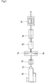
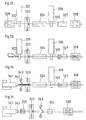
- Fig. 12 schematically shows the structure of the apparatus used in Example 13 for manufacturing the high-pressure composite pipe according to the present invention.
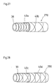
- Fig. 17 is a perspective view showing the structure of the high-pressure composite pipe manufactured in another embodiment of the present invention.
- Fig. 18 is a perspective view showing the structure of the high-pressure composite pipe manufactured in yet another embodiment of the present invention.
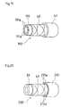
- Fig. 20 is a perspective view showing the structure of the high-pressure composite pipe manufactured in still another embodiment of the present invention.
- Fig. 22 is a sectional view showing the structure of the high-pressure composite pipe manufactured in a yet further embodiment of the present invention.
- Fig. 25 illustrates the operation of the inner layer stretching machine used in Example 19 for manufacturing the high-pressure composite pipe according to the present invention.
- Fig. 28 is a perspective view showing the structure of the high-pressure composite pipe manufactured in Comparative Example 8.
- Fig. 37 is an essential sectional view describing the second step in the embodiment of the high-pressure composite pipe joining method according to the present invention.
- Fig. 39 is a perspective view showing an example of the annular band used in another embodiment of the high-pressure composite pipe joining method according to the present invention.
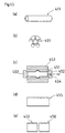
- Figs. 41(a)-(d) describe a series of steps for preparing the tube-shaped element to be used in yet another embodiment of the high-pressure composite pipe joining method according to the present invention.
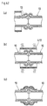
- Figs. 42(a)-(c) are essential sectional views describing a series of steps in another different embodiment of the high-pressure composite pipe joining method according to the present invention, wherein the tube-shaped element illustrated in Fig. 41(d) is employed.
- Figs. 43(a)-(c) are essential sectional views describing a series of steps in still another embodiment of the high-pressure composite pipe joining method according to the present invention, wherein the tube-shaped element illustrated in Fig. 41(d) is employed.
- Figs. 44 (a) and (b) are illustrated descriptions of a series of steps for manufacturing the tube-shaped element to be used in further another embodiment of the high-pressure composite pipe joining method according to the present invention.
- Figs. 45 (a)-(e) are illustrated descriptions of a series of steps for manufacturing the tube-shaped element to be used in a yet further embodiment of the high-pressure composite pipe joining method according to the present invention.
- This polyolefin sheet was paid out at a speed of 1 m/min., guided through a heating oven at 120°C, and taken up at a speed of 30 m/min. Thus obtained was a stretched polyolefin sheet with a stretching ratio of 30 and a thickness of 0.15 mm.
- the payout and takeup operations were conducted by pinch rolls.
- an adhesive sheet was laminated on one side of the stretched polyolefin sheet.
- the adhesive sheet was continuously laminated on the stretched polyolefin sheet, and thus obtained was a stretched composite sheet ready for winding.
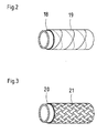
- the above-mentioned reinforcing layer sheet was slit into a width of 90 mm to give elongated reinforcing layer tapes. Two such tapes were wound one after another on the external circumference of the pipe at ⁇ 60° relative to the axis of the high-pressure composite pipe, with the adhesive sheet being in contact with the inner layer.
- a reinforcing layer sheet comprising a stretched composite sheet was obtained in the same manner as in Example 1.
- thermoplastic polyolefin resin was supplied into the single-screw extruder 11.
- the resin was molded into an inner layer pipe having a 60 mm outer diameter and a 3-mm-thick wall.
- two elongated reinforcing layer tapes obtained by slitting the above-mentioned reinforcing layer sheet into a width of 90 mm, were wound one after another on the inner layer pipe at ⁇ 60° relative to the axis of the pipe, using a pair of spiral winders 14.
- the tape-wound resin pipe was carried through the hot air oven 15 and heated to the surface temperature of 130°C. Thereafter, the pipe was cooled in the cooling water pool 16 to give a high-pressure composite pipe.
- the reinforcing layer sheet was made up of a stretched composite sheet.
- a reinforcing layer sheet comprising a stretched composite sheet was obtained in the same manner as in
- Example 2 The operation of Example 2 was followed except for replacing the spiral winders with a sheet braider.
- a sheet braider a braiding machine (braider) which is usually used for the production of a high-pressure hose was utilized by converting its payout apertures from the fiber payout specification to the sheet payout specification.
- the payout capacity was 32 sheets.
- the resins for the inner layer and the outer layer were extruded under the condition where the temperatures of the extruder barrel and the die were both 200°C.
- the reinforcing layer sheet was made up of a stretched composite sheet.
- Example 6 The process of Example 6 was followed without using the spiral winders. After the inner layer was formed by extrusion, the outer layer was extruded from the coating die, without winding the reinforcing layer sheet. Thus obtained was a pipe-shaped element composed of two resin layers.
- the reinforcing layer sheet use was made of a polyester fiber with a strength of 4.8 g/denier.
- the resins for the inner layer and the outer layer were the same as those used in Example 1. Following the extrusion forming of the inner layer, the polyester fiber was wound in a braided manner at ⁇ 60° relative to the axis of the pipe-shaped element. Similar to Example 8, the weight of the polyester fiber was adjusted to about 60 grams in a one-meter segment of the pipe-shaped element.
- the reinforcing layer sheet use was made of a stainless steel wire with a strength of 3.0 g/denier.
- the resins for the inner layer and the outer layer were the same as those used in Example 1.
- the stainless steel wire was wound in a braided manner at ⁇ 60° relative to the axis of the pipe-shaped element. Similar to Example 8, the weight of the stainless steel wire was adjusted to about 60 grams in a one-meter segment of the pipe-shaped element.
- a reinforcing layer sheet was manufactured in the same manner as in Example 1, except that the adhesive sheet was not laminated.
- polyolefin resins were supplied into the first single-screw extruder 51a and the second single-screw extruder 51b.
- the resins were molded into a double pipe having a 60 mm outer diameter and a 3-mm-thick wall.
- the internal part constituted a 2.7-mm-thick inner layer of high-density polyethylene, and the external part established a 0.3-mm-thick adhesion layer.
- the adhesion layer was made by using an adhesive polyethylene (Admer HF500, manufactured by Mitsui Chemicals, Inc.).
- Admer HF500 an adhesive polyethylene
- high-density polyethylene resins were extruded under the condition where the temperatures of the extruder barrel and the die were both 200°C.
- a reinforcing layer sheet comprising a stretched composite sheet was obtained in the same manner as in Example 1, except that the lamination was applied on both surfaces instead of one surface.
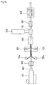
- Fig. 10 is an illustration of an apparatus for manufacturing the high-pressure composite pipe according to this Example.
- Fig. 10 shows a first single-screw extruder 61a, a second single-screw extruder 61b, a two-layer two-component extrusion die 62 located at their ends, a cooling die 63, a pair of spiral winders 64, a hot air oven 65, a pair of late-stage single-screw extruders 68a, 68b, a two-layer two-component extrusion coating die 69 located at their ends, a cooling die 70, and a takeup machine 67.
- the two-layer two-component extrusion coating die 69 equipped at the ends of a pair of late-stage single-screw extruders 68a, 68b, and the cooling die 70, two species of resins were extruded in two layers to coat the reinforcing layer-wound composite pipe, and thereby formed a double layer.
- the internal part constituted a 0.3-mm-thick outer adhesion layer
- the external part established a 1.2-mm-thick outer layer of high-density polyethylene.
- the outer layer and the outer adhesion layer were made of the high-density polyethylene and the adhesive polyethylene used in Example 10, respectively.
- the resins for the outer layer and the adhesion layer were extruded under the condition where the temperatures of the extruder barrel and the die were both 200°C.
- a reinforcing layer sheet comprising a stretched composite sheet was obtained in the same manner as in Example 10.
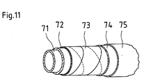
- a high-pressure composite pipe shown in Fig. 11 was obtained in the same manner as in Example 11.
- each of Examples 9 to 12 provided a high-pressure composite pipe (outer diameter 63 mm, wall thickness 4.5 mm) of the present invention, in which the reinforcing layer sheet was wound one layer after another at symmetric angles relative to the axis of the pipe, substantially in a gapless manner.
- thermoplastic polyolefin resin was supplied into the single-screw extruder 81.
- the resin was molded into an inner layer pipe having a 60 mm outer diameter and a 3-mm-thick wall.
- stretched composite sheets with a width of 94.2 mm were fed from a pair of payout rolls 84 and laminated such that the stretching direction was oriented along the axis of the pipe.
- Two elongated reinforcing layer tapes obtained by slitting the above reinforcing layer sheet into a width of 90 mm, were wound one after another on the inner layer pipe at ⁇ 60° each relative to the axis of the pipe, using a pair of spiral winders 85.
- the tape-wound resin pipe was carried through the far-infrared heating oven 86 and heated to the surface temperature of 130°C. Thereafter, the pipe was cooled in the cooling die 87 to give a high-pressure composite pipe.
- Fig. 13 illustrates the inner layer 89, the reinforcing layer 90 for axial reinforcement, and the reinforcing layer 91 chiefly for circumferential reinforcement.
- a reinforcing layer sheet comprising a stretched composite sheet was obtained in the same manner as in Example 1.
- Fig. 14 is an illustration of an apparatus for manufacturing the high-pressure composite pipe according to this Example.
- Fig. 14 shows an early-stage single-screw extruder 101 whose end is equipped with an extrusion die 102, a cooling die 103, payout rolls 104, a pair of spiral winders 105, a far-infrared heating oven 106, a late-stage single-screw extruder 109 whose end is equipped with an extrusion die 110, a cooling die 107, and a takeup machine 108.
- Two elongated reinforcing layer tapes obtained by slitting the above reinforcing layer sheet into a width of 90 mm, were wound one after another on the inner layer pipe at ⁇ 60° each relative to the axis of the pipe, using a pair of spiral winders 105.
- the tape-wound resin pipe was carried through the far-infrared heating oven 106 and heated to the surface temperature of 130°C.
- the reinforcing layer sheet was made up of a stretched composite sheet.
- Fig. 15 illustrates the inner layer 111, the reinforcing layer 112 for axial reinforcement, the reinforcing layer 113 chiefly for circumferential reinforcement, and the outer layer 114.
- each of Examples 13 and 14 provided a high-pressure composite pipe (outer diameter 63 mm, wall thickness 4.5 mm) of the present invention, in which the reinforcing layer sheet was wound such that one layer was laid along the axis of the pipe and each one layer was laid at a symmetric angle relative to the axis of the pipe and substantially in a gapless manner.
- a 1000-mm-long high-pressure composite pipe was fixed at both ends by measurement jigs 121.
- Pressure was applied inside the pipe by a pump 122 to measure a destructive internal pressure of the pipe.
- the pressure was raised at a rate of 5 kgf/min., until the pressure could not be raised any further or the pressure dropped.
- the internal pressure measured at that moment was determined as the destructive internal pressure.
- the high-pressure composite pipe was continuously subjected to an internal pressure of 12 kgf/cm 2 by 80°C water under an 80°C atmosphere. Under these conditions, each pipe was measured for the pressure endurance time.
- Each pipe was subjected to the three-point bending test.
- the distance between the supports was 1000 mm.
- Table 2 proved that the high-pressure composite pipes of the present invention were excellent in destructive internal pressure property, which indicated their high internal pressure resistance.
- the pipe-shaped element of Comparative Example 3 cracked due to weeping from between stiches of the polyester fiber, and the pipe-shaped element of Comparative Example 4 broke due to the water penetrating from the pipe ends into the interface between the stainless steel wire and the outer layer resin.
- none of the high-pressure composite pipes of Examples suffered from any such rupture.
- Winding Method Winding Angle Destructive Internal Pressure (kgf/cm 2 ) Internal Pressure Endurance Time (hr) Ex. 9 Winding 60° 74 ⁇ 200 Ex. 10 Winding 60° 76 ⁇ 200 Ex. 11 Winding 60° 76 ⁇ 200 Ex. 12 Winding 60° 80 ⁇ 200 Comp.Ex. 5 N/A N/A 38 105
- Table 3 confirmed that the high-pressure composite pipes of the present invention were excellent in destructive internal pressure property, which indicated their high internal pressure resistance.
- Table 4 proved that the high-pressure composite pipes of the present invention were excellent in destructive internal pressure property, which indicated their high internal pressure resistance.
- Fig. 17 schematically shows the structure of an embodiment which corresponds to the high-pressure composite pipe of Invention 6.
- a high-pressure composite pipe 170 comprises a pipe-shaped inner layer 39 made of a polyethylene resin, a reinforcing layer 182 formed by spirally winding a stretched polyethylene resin sheet (i.e. a stretched polyolefin resin sheet) on an external circumferential surface of the inner layer 39, an insulating layer 171 made of a foamable polyethylene resin and laminated on the reinforcing layer 182, and an outer layer 41 made of a polyethylene resin and laminated on the insulating layer 171.
- a stretched polyethylene resin sheet i.e. a stretched polyolefin resin sheet
- the reinforcing layer 182 laminated on the inner layer 39 has a two-layer structure, wherein a stretched polyethylene resin sheet, prepared in a strip of proper width, is spirally wound at an inclination angle between 30° and 90° relative to the axis of the inner layer 39, and another stretched polyethylene resin sheet is spirally wound thereon in the reverse inclination direction.
- Fig. 18 schematically shows the structure of an embodiment which corresponds to the high-pressure composite pipe of Invention 9.
- a high-pressure composite pipe 180 comprises a pipe-shaped inner layer 39 made of a polyethylene resin, a reinforcing layer 182 formed by spirally winding a stretched polyolefin resin sheet on an external circumferential surface of the inner layer 39, and an outer layer 181 made of a polyethylene resin foam and laminated on the reinforcing layer 182.
- the reinforcing layer 182 laminated on the inner layer 39 has a two-layer structure, wherein a stretched polyethylene resin sheet, prepared in a strip of proper width, is spirally wound at an inclination angle between 30° and 90° relative to the axis of the inner layer 39, and another stretched polyethylene resin sheet is spirally wound thereon in the reverse inclination direction.
- a polyethylene resin is extruded in pipe form by a single-screw extruder. Then, using spiral winders, stretched polyethylene resin sheets, prepared in a strip of predetermined width, are spirally wound around the external circumferential surface of the inner layer 39 to provide the reinforcing layer 182.
- the stretched polyethylene resin sheet is made by stretching a high-density polyethylene sheet, under heating, at a stretching ratio of about 30, followed by a crosslinking treatment.
- the laminate After the inner layer 39 of a polyethylene resin is laminated with the reinforcing layer 182 made of a stretched polyethylene resin sheet, the laminate is introduced into an extrusion coating die. While the laminate passes through the extrusion coating die, a foamable polyethylene resin is extruded into the extrusion coating die and allowed to foam. Thus formed is the outer layer 181, made of a polyethylene resin foam, which coats the reinforcing layer 182. When the laminate comes out of the extrusion coating die, it is cooled in the cooling water pool to give the high-pressure composite pipe 180 shown in Fig. 18.
- the polyethylene inner layer 39 is spirally wrapped by the stretched polyethylene resin sheet having a remarkable tensile strength, whereby the inner layer 39 is fortified by the reinforcing layer 182.
- the pipe can be used as a hot-water pipe or as a water supply pipe. During the winter in the cold region, such a water supply pipe can prevent water therein from freezing, without an aid of a heat insulating material.
- the outer layer 181 made of a polyethylene resin foam covers and protects the reinforcing layer 182 which is formed by spirally winding the stretched polyethylene resin sheet. Since the reinforcing layer 182 is not directly exposed to an external pressure, the reinforcing layer 182 is allowed to reinforce the inner layer 39 in a stable manner over a long period.
- the outer layer 181 of the high-pressure composite pipe 180 may be made of various synthetic resin foams, instead of the polyethylene resin foam. Nevertheless, when the polyethylene resin foam is of the same species as the polyethylene resin for the inner layer 39 and the stretched polyethylene resin sheet for the reinforcing layer 182, the high-pressure composite pipe 180 can be readily recycled.
- a polyethylene resin foam is utilized exclusively for the outer layer 181.
- the inner layer 39 may be composed of a polyethylene resin foam.
- the inner layer 39 made of a highly insulative polyethylene resin foam can be also used suitably in a pipe arrangement for water or hot-water supply.
- both the inner layer 39 and the outer layer 181 may be made of a polyethylene resin foam. This structure apparently enhances the insulating effect to an extended degree.
- Fig. 19 to Fig. 21 schematically show the structures of embodiments which correspond to the high-pressure composite pipe of Invention 10.
- a high-pressure composite pipe 190 shown in Fig. 19, comprises a pipe-shaped inner layer 191 made of a polyethylene resin, a reinforcing layer 40 obtained by spirally winding a stretched polyethylene resin sheet (i.e. a stretched polyolefin resin sheet) on an external circumferential surface of the inner layer 191, and an outer layer 41 made of a polyethylene resin and laminated on the reinforcing layer 40.
- a stretched polyethylene resin sheet i.e. a stretched polyolefin resin sheet
- the inner layer 191 of a polyethylene resin includes a plurality of hollow portions 191a, which extend along the axis as equally spaced along the circumference.
- the reinforcing layer 40 laminated on the inner layer 191 has a two-layer structure, wherein a stretched polyethylene resin sheet, prepared in a strip of proper width, is spirally wound at an inclination angle between 30° and 90° relative to the axis of the inner layer 191, and another stretched polyethylene resin sheet is spirally wound thereon in the reverse inclination direction.
- the high-pressure composite pipe 190 of the above structure is manufactured in the following manner.
- a polyethylene resin is extruded in pipe form by a single-screw extruder to form the inner layer 191, through which a plurality of hollow portions 191a extend along the axis as equally spaced along the circumference.
- a stretched polyethylene resin sheet prepared in a strip of predetermined width, is wound spirally at a given angle around the external circumferential surface of the inner layer 191.
- another stretched polyethylene resin sheet is wound spirally in the reverse inclination direction to provide the reinforcing layer 40.
- the stretched polyethylene resin sheet is made by stretching a high-density polyethylene sheet, under heating, at a stretching ratio of about 30, followed by a crosslinking treatment.
- the laminate After the inner layer 191 of a polyethylene resin is laminated with the reinforcing layer 40 made of a stretched polyethylene resin sheet, the laminate is introduced into an extrusion coating die. While the laminate passes through the extrusion coating die, the reinforcing layer 40 is coated with a polyethylene resin, as the outer layer 41, which is extruded into the extrusion coating die. When the laminate comes out of the extrusion coating die, it is cooled in the cooling water pool to give the high-pressure composite pipe 190 shown in Fig. 19.
- the inner layer 191 requires a less amount of polyethylene resin.
- the reinforcing layer 40 prepared by spirally winding the stretched polyethylene resin sheet, is covered and protected by the outer layer 41 made of a polyethylene resin. Free from direct exposure to an external pressure, the reinforcing layer 40 is prevented from rupture or the like. Furthermore, since the inner layer 191, the reinforcing layer 40 and the outer layer 41 are made of the same species of polyethylene resin, this high-pressure composite pipe 190 is readily recyclable and, compared with a vinyl chloride resin pipe, superior in quakeproof property.
- Fig. 20 schematically illustrates the structure of another embodiment which corresponds to the high-pressure composite pipe of Invention 10.
- the outer layer 213 is obtainable in a reduced weight using a less amount of resin, which results in economical production.
- partitions between adjacent hollow portions 213a provide reinforcement, whereby the outer layer 213 does not break under an external pressure.
- Fig. 21 schematically shows the structure of yet another embodiment which corresponds to the high-pressure composite pipe of Invention 10.
- the high-pressure composite pipe 210 weighs less and can be manufactured more economically.
- Fig. 22 is a sectional view showing an embodiment which corresponds to the high-pressure composite pipe of Invention 11.
- the external circumferential surface of the outer layer 413 is provided with a plurality of reinforcing ribs 413b, each of which projects radially and circumferentially and is equally spaced from the others along the axis. No hollow portions are formed in the inner layer 39 and the outer layer 413. Except for this modification, its structure is the same as the high-pressure composite pipe 190 shown in Fig. 19.
- Example 1 The manufacture process of Example 1 was followed exactly, except that the adhesive sheet used was a 200- ⁇ m-thick sheet of a thermoplastic elastomer (Mi-lastomer 5030N, Mitsui Chemicals, Inc.).
- the thermoplastic elastomer had a modulus of tensile elasticity of 300 kgf/cm 2 .
- Example 1 The manufacture process of Example 1 was followed exactly, except that the adhesive sheet used was a 25- ⁇ m-thick sheet of a silane crosslinkable low-density polyethylene (LINKLON XF800T, MITSUBISHI CHEMICAL CORPORATION).
- the adhesive sheet used was a 25- ⁇ m-thick sheet of a silane crosslinkable low-density polyethylene (LINKLON XF800T, MITSUBISHI CHEMICAL CORPORATION).
- the resulting high-pressure composite pipes were immersed in 80°C hot water for one hour, in order to effect crosslinking at the adhesion layer.
- the crosslinking degree was about 80%, as evaluated in terms of gel fraction.
- a 1000-mm-long high-pressure composite pipe was fixed at both ends by measurement jigs 121.
- Pressure was applied inside the pipe by a pump 122 to measure a destructive internal pressure of the pipe.
- the pressure was raised at a rate of 5 kgf/min., until the pressure could not be raised any further or the pressure dropped.
- the internal pressure measured at that moment was determined as the destructive internal pressure.
- the high-pressure composite pipe was continuously subjected to an internal pressure of 12 kgf/cm 2 by 80°C water under an 80°C atmosphere. Under these conditions, each pipe was measured for the pressure endurance time.
- the high-pressure composite pipe was continuously subjected to internal pressures of 0 kgf/cm 2 and 40 kgf/cm 2 which were applied at a cycle of 1 Hz, by 23°C water under a 23°C ambient atmosphere. Under these conditions, each high-pressure composite pipe was measured for the cycles of enduring the pressure.
- Destructive Internal Pressure (kgf/cm 2 ) Internal Pressure Endurance Time (hr) Pulsation Cycles Ex. 1 66 ⁇ 200 ⁇ 10000 Ex. 15 64 ⁇ 200 ⁇ 18000 Ex. 16 65 ⁇ 400 ⁇ 15000
- the reinforcing sheet used in Example 1 was fed into an apparatus shown in Fig. 23 which comprises a combination of four 10-mm-diameter iron rolls 231 ⁇ 231, in which the sheet was guided along a zigzag pass line.
- the thus treated reinforcing sheet was a tensile material which had a low modulus of initial tensile elasticity, as found in Table 6.
- Example 1 the stretched polyolefin resin sheet was arranged to show a gel fraction of not less than 20% and a shrinkage stress of not less than 0.1 MPa.
- the measurement results are shown in Table 8.
- Example 1 which showed a gel fraction of not less than 20% and a shrinkage stress of not less than 0.1 MPa, were also included.
- a stretched polyolefin resin sheet for a high-pressure composite pipe was obtained in the same manner as in Example 1, except that the materials therefor also contained 3 parts by weight of ethyl 4-dimethylaminobenzoate.
- the irradiation time of the high pressure mercury lamp was altered to 20 seconds.
- a high-pressure composite pipe was manufactured in the same manner as in Example 1.
- a stretched polyolefin resin sheet for a high-pressure composite pipe was obtained in the same manner as in Example 1, except that the material therefor was comprised singly of a high-density polyethylene. In addition, this process omitted crosslinking by irradiation of the high pressure mercury lamp.
- a high-pressure composite pipe was manufactured in the same manner as in Example 1.
- Fig. 24 and Fig. 25 are schematic views of the inner layer stretching machine.
- the thick-walled inner layer pipe base was stretched 1.6 times in the circumferential direction. Later, a tapered portion was cut off to obtain a stretched inner layer pipe (outer diameter 60 mm, wall thickness 3 mm).
- the inner layer stretching machine comprises a mandrel 261, a clamp 262, a shaft 263 for holding the mandrel 261, and a die 264.
- the inner layer pipe 265 is pulled by the clamp 262 along the mandrel 261. This process provides a stretched inner layer pipe 266 which is stretched both axially and circumferentially.
- the thick-walled inner layer pipe was stretched 1.5 times in the axial direction and 1.3 times in the circumferential direction.
- a stretched inner layer pipe (outer diameter 60 mm, wall thickness 3 mm).
- Example 19 With the use of this stretched inner layer pipe, a high-pressure composite pipe was obtained in the same manner as in Example 19.
- the high-pressure composite pipes of Example 19 and Example 20 were subjected to the internal pressure destructive test, the internal pressure creep test and the pipe bending test. The results were shown in Table 9.
- Destructive Hydraulic Pressure (kgf/cm 2 ) Internal Pressure Endurance Time (hr) Modulus of Bending Elasticity (kgf/cm 2 ) Ex. 19 77 ⁇ 300 9000 Ex. 20 75 ⁇ 300 12000
- Fig. 27 and Fig. 28 are perspective views showing the structures of the high-pressure composite pipes of Example 21 and Comparative Example 8, respectively. Description is hereinafter made with reference to these drawings.
- Four reinforcing layer sheet strips were prepared by slitting the reinforcing layer sheet into widths of 16 mm and 64 mm.
- the 16-mm-wide reinforcing layer sheets 40a were wound at ⁇ 85° each relative to the axis of the high-pressure composite pipe, with the adhesive sheets contacting on the inner layer.
- the 64-mm-wide reinforcing layer sheets 40b were wound at ⁇ 70° each relative to the axis of the high-pressure composite pipe.
- the reinforcing layer sheets made a total of four layers.
- the sheet-wound resin pipe 270 wrapped with these sheets was heated in a far-infrared oven until the surface temperature reached 130°C.
- the reinforcing layer sheets 40a, 40b were fused on the high-density polyethylene pipe for the inner layer 39.
- Four reinforcing layer sheet strips were prepared by slitting the reinforcing layer sheet into a width of 33 mm. Two of them, as reinforcing layer sheets 40c, were wound on the external circumference of the inner layer 39 at ⁇ 80° each relative to the axis of the high-pressure composite pipe, with the adhesive sheets contacting on the inner layer. On this external circumference, the remaining two reinforcing layer sheets 40d were wound at ⁇ 80° in the similar manner.
- Comparative Example 8 structurally corresponds to the high-pressure composite pipe of Invention 1
- Example 21 (as the high-pressure composite pipe of Invention 15) contains a limitation on the reinforcing layer.
- the instant comparison of Comparative Example 8 with Example 21 is intended in terms of destructive pressure and pulsation cycles.
- the performance evaluation tests were conducted in the same manner as the above-mentioned tests. The results were compiled in Table 10. As indicated in Table 10, Example 21 was superior to Comparative Example 8 in the pulsation resistance performance.
- Winding Angle Destructive Internal Pressure (kgf/cm 2 ) Pulsation Cycles Ex. 21 ⁇ 85°, ⁇ 70° 92 18000 Comp.Ex. 8 ⁇ 80° 90 10000
- the resins for the inner and outer layers were extruded under the condition where the temperatures of the extruder barrel and the die were both 200°C.
- the stretched polyolefin resin sheet 60-mm-wide strips were wound in two layers at ⁇ 70° relative to the axis of the high-pressure composite pipe. During the winding, the surface temperature of the inner layer was kept at 150°C.
- FIG. 30 An apparatus for manufacturing a high-pressure composite pipe is illustrated in Fig. 30.
- This manufacturing appartus is different from the one shown in Fig. 29, in that air is supplied from the core projecting from an extrusion die 302, thereby raising the pressure in a space closed by a plug 308 which is disposed in the downstream side of the manufacturing apparatus in such a manner as to establish close contact with the inner layer.
- a lamination pressure is applied to the inner layer and the stretched polyolefin resin sheet wound thereon.
- the manufacture process in Example 23 was the same as in Example 22.
- the stretched polyolefin resin sheet obtained in Example 1 was thermally fused on one surface of a preformed 2.5-mm-thick polyethylene sheet.
- FIG. 31 An apparatus for manufacturing the high-pressure composite pipe is illustrated in Fig. 31.
- An inner layer pipe having a 51 mm inner diameter and a 3-mm-thick wall was formed through an extrusion die 292 equipped at the end of a single-screw extruder 291.
- the core of the extrusion die 292 protrudes in the downstream side of the manufacturing apparatus, serving as a mandrel for the winding.
- the inner layer pipe was wrapped by a stretched composite sheet strip slit into a predetermined width, and another stretched composite sheet.
- Following passage through a far-infrared heater 304 there was produced a high-pressure composite pipe having a 63 mm outer diameter and a 6-mm-thick wall.
- the high-pressure composite pipe was taken out by a takeup machine 297.
- the inner and outer layers were made of the same resins as used in Example 1.
- the stretched composite sheet a 60-mm-wide strip was wound on the inner layer pipe at +70° relative to the axis of the high-pressure composite pipe, and, on this sheet, another stretched composite sheet was wound at -70°.
- the surface temperature of the inner layer was kept at 150°C.
- the far-infrared heater 304 heated at an atmospheric temperature of 165°C, heating was evenly applied in the circumferential direction of the pipe to give a high-pressure composite pipe.
- FIG. 32 An apparatus for manufacturing the high-pressure composite pipe is illustrated in Fig. 32.
- a cut iron mandrel was supplied by an iron mandrel feeder 329 in the upstream side of the manufacturing apparatus, and coating was effected on the mandrel by means of an extrusion coating die 322 equipped at the end of a single-screw extruder 321.
- an extrusion coating die 322 equipped at the end of a single-screw extruder 321.
- spiral winders 323 stretched composite sheet strips, slit into a predetermined width, were wound on the inner layer pipe.
- the sheet-wound pipe was carried through a far-infrared heater 324.
- FIG. 33 An apparatus for manufacturing the high-pressure composite pipe is illustrated in Fig. 33.
- a coiled iron mandrel was supplied in the upstream side of the manufacturing apparatus, and coating was effected on the mandrel by means of an extrusion coating die 332 equipped at the end of a single-screw extruder 331.
- the later-stage of the manufacturing apparatus is the same as in Example 25 shown in Fig. 32, and not described any further at the moment.
- the coiled iron mandrel an endless iron sheet was supplied in spiral tubular form, with the edges slightly overlapping on each other. In the middle of the takeup machine 328, the tubular mandrel was returned into sheet form and carried back to the upstream of the manufacturing apparatus via a hollow space inside the mandrel.
- the inner and outer layers were made of the same resins as used in Example 22.
- the stretched composite sheet 60-mm-wide strips were wound on the inner layer pipe in two layers at ⁇ 70° relative to the axis of the high-pressure composite pipe.
- the far-infrared heater 324 was adjusted to an atmospheric temperature of 165°C.
- FIG. 34 An apparatus for manufacturing the high-pressure composite pipe is illustrated in Fig. 34.
- This apparatus is capable of forming a pipe-form extrudate through an extrusion coating die 342 equipped at the end of a single-screw extruder 341.
- the external circumference of a core protruding from the extrusion coating die 342 was utilized as a mandrel, which was wrapped by stretched composite sheets fed from a stretched composite sheet payout machine 343 and by stretched composite sheets fed from spiral winders 323.
- a resin was extruded from the single-screw extruder 326 and coated as the outer layer.
- the inner layer was extruded in tubular form into the stretched composite sheet.
- Subsequent cooling in the cooling die 327 provided a high-pressure composite pipe having a 63 mm outer diameter and a 6-mm-thick wall.
- the high-pressure composite pipe was taken out by the takeup machine 328.
- the inner and outer layers were made of the same resins as used in Example 22.
- the stretched composite sheet 60-mm-wide strips were wound on the inner layer pipe in two layers at ⁇ 70° relative to the axis of the high-pressure composite pipe, and another layer was wound therein along the axis.
- the far-infrared heater 324 was adjusted to an atmospheric temperature of 165°C.
- FIG. 35 An apparatus for manufacturing the high-pressure composite pipe is illustrated in Fig. 35.
- An inner layer pipe having a 51 mm inner diameter and a 3-mm-thick wall was formed through an extrusion coating die 342 equipped at the end of a single-screw extruder 341, and a cooling die 357. Then, stretched composite sheet strips, slit into a predetermined width, were wound around the inner layer pipe, using spiral winders 323. A polyethylene sheet was paid out from a sheet payout machine 343 in such a manner as to envelop the external circumference.
- the sheet-covered pipe was led through a heating die 355 to produce a high-pressure composite pipe having a 63 mm outer diameter and a 6-mm-thick wall.
- the high-pressure composite pipe was taken out by the takeup machine 328.
- the inner layer was made of the same resin as used in Example 22.
- the material for the polyethylene sheet was the outer layer resin employed in Example 22.
- As for the stretched composite sheet 60-mm-wide strips were wound on the inner layer pipe in two layers at ⁇ 70° relative to the axis of the high-pressure composite pipe. The temperature of the heating die 355 was adjusted to 135°C.
- each high-pressure composite pipe 10 is heated through contact with a heated hot plate 361.
- each high-pressure composite pipe 10 is not forcibly pressed against the hot plate 361, but allows its end to be heated into a melted state by a certain length.
- the joining method of the present invention can be applied to join a pair of high-pressure composite pipes 10. Since the joint area is joined strongly along the entire circumference, there is no fear of water leakage or fructure at the joint area.
- Fig. 39 is a perspective view showing an example of an annular band to be used in another embodiment of the method of the present invention for joining the high-pressure composite pipes.
- Fig. 40 is an essential sectional view for describing a step in the embodiment using the annular band shown in Fig. 39.
- annular band 390 is disconnected by a slit 396.
- An annular band base 393 is equipped with collars 392, 392 which are bent externally and project from both ends of the annular band base 393.
- the collars 392, 392 include bolt holes 391 ⁇ 391 for fastening.
- a groove 394 runs circumferentially in the middle of the internal circumferential surface. Ridges 395, 395, each having a round tip, extend circumferentially along both side edges of the internal circumferential surface. The ridges 395 only need to have their tips rounded. As illustrated in Fig. 40, when the annular band 390 is fastened on the fusion point of the high-pressure composite pipes 10, 10, the annular band 390 can fix the high-pressure composite pipes 10, 10 by biting, in an indenting manner, into the entirety of the pipes 10, 10.
- the slit in the annular band base 393 should not be limited at one position.
- the annular band base may be constituted with two or more sections.
- the annular band 390 is applicable to the joint area created by the method for joining the high-pressure composite pipes, as described with reference to Fig. 38.
- this joining method as shown in Fig. 40, while the slit 394 in the annular band base 393 is forced open, mounting is effected such that the groove 394 can house a bulge which protrudes outwardly and circumferentially along the fusion point, and that the tips of the ridges 395 can contact, on both sides of the bulge, with the external circumferential surfaces of the high-pressure composite pipes 10, 10.
- bolts are inserted through the bolt holes 391 ⁇ 391 and screwed with nuts.
- FIG. 46 shows a joining method using an old-fashioned annular band, in which a conventional annular band 460 has ridges 46a, 46a with pointed tips.
- the ridges 46a, 46a cannot bite in any deeper than the outer layers of high-pressure composite pipes 461, 461, and the outer layers are likely to be cut and peeled off at the bitten positions.
- the annular band 460 fails to provide satisfactory fixation.
- the tube-shaped element constitutes a reinforcing material to be applied at a joint area of the high-pressure composite pipes.
- a monoaxially stretched polyethylene resin sheet 412 is wound on a core 411 in one turn, with the stretching direction A being perpendicular to the axis of the core 411.
- the sheet was reformed into the wound shape under heating at a temperature not higher than its heat shrinkage temperature, and removed thereafter.
- Fig. 41(b) its ends are ultrasonically fused together to form a tube-shaped element 413 shown in Fig. 41(c).
- the tube-shaped elements 413 are laminated in several layers, with the ultrasonic fusion points 414 ⁇ 414 staggered from each other. Thereby produced is a laminated tube-shaped element 410.
- Figs. 42(a)-(c) are essential sectional views describing a series of steps in another different embodiment of the high-pressure composite pipe joining method according to the present invention, wherein the tube-shaped element illustrated in Fig. 41(d) is employed.
- the tube-shaped element 410 shown in Fig. 41(d) is applied to the fusion point of the high-pressure composite pipes formed in the joining method described with reference to Fig. 38.
- the tube-shaped element 410 Prior to the joining step, the tube-shaped element 410 is positioned to accommodate one of the high-pressure composite pipes 10, as illustrated in Fig. 42(a).
- the tube-shaped element 410 is displaced and approximately centered over the fusion point of the high-pressure composite pipes 10, 10, on which the tube-shaped element 410 is tightly attached by heat shrinkage, as shown in Fig. 42(c).
- Figs. 43(a)-(c) are essential sectional views describing a series of steps in still another embodiment of the high-pressure composite pipe joining method according to the present invention, wherein the tube-shaped element illustrated in Fig. 41(d) is employed.
- This joining method includes the step of removing a bulge 431 which projects outwardly and circumferentially along the fusion point in the joint area of the high-pressure composite pipes 10, 10. Afterwards, the tube-shaped element 410 is placed over the periphery of the removal area, which is covered tightly by thermally shrinking the tube-shaped element 410.
- the shrunk tube-shaped element 410 can attach more tightly on the surface of the joint area.
- Figs. 44 (a) and (b) are illustrated descriptions of a series of steps for manufacturing the tube-shaped element to be used in further another embodiment of the high-pressure composite pipe joining method according to the present invention.
- This tube-shaped element 440 can also reinforce the fusion point between the high-pressure composite pipes, as described in relation to Fig. 42 and Fig. 43.
- a tube-shaped element for serving as the reinforcing material is made of a monoaxially stretched polyolefin resin sheet.
- a biaxially stretched polyolefin resin sheet can be also employed to prepare a similar tube-shaped element which is capable of serving as the reinforcing material.
- Figs. 45 (a)-(e) are illustrated descriptions of a series of steps for manufacturing the tube-shaped element to be used in a yet further embodiment of the high-pressure composite pipe joining method according to the present invention.
- This tube-shaped element constitutes a reinforcing material to be used at a joint area between the high-pressure composite pipes.
- the reinforcing material is prepared with the use of an extrusion-molded thermoplastic resin pipe 451 shown in Fig. 45 (a).
- the thermoplastic resin pipe 451 is rotated under heating by a heater.
- the heated thermoplastic resin pipe 451 is placed in an external mold 453, with both ends thereof being sealed by covers 452, 453.
- thermoplastic resin pipe 451 Under this condition, pressure is raised by introducing air from an air hole 454 in the cover 452, so that the thermoplastic resin pipe 451 can enlarge diametrically until its external circumferential surface establishes full contact with the internal circumferential surface of the external mold 453. Afterwards, as illustrated in Figs. 45(d) and (e), a pipe 455 is removed and cut to give tube-shaped elements 450, each of which is oriented in the circumferential direction.
- the tube-shaped element 450 can also reinforce the fusion point between the high-pressure composite pipes, as described in relation to Fig. 42 and Fig. 43.
- the high-pressure composite pipes of the present invention are useful and advantageous in various applications.
- the present invention also provides a method for firmly joining high-pressure composite pipes in a simple manner. This method is effective for reliable construction of high-pressure composite pipes, by making such joining adjustable to high-pressure composite pipes of any configuration.
Landscapes
- Engineering & Computer Science (AREA)
- Mechanical Engineering (AREA)
- General Engineering & Computer Science (AREA)
- Physics & Mathematics (AREA)
- Plasma & Fusion (AREA)
- Thermal Sciences (AREA)
- Laminated Bodies (AREA)
- Rigid Pipes And Flexible Pipes (AREA)
- Lining Or Joining Of Plastics Or The Like (AREA)
- Shaping Of Tube Ends By Bending Or Straightening (AREA)
- Branch Pipes, Bends, And The Like (AREA)
- Shaping By String And By Release Of Stress In Plastics And The Like (AREA)
Abstract
Description
| Winding Method | Winding Angle | Destructive Internal Pressure (kgf/cm2) | Internal Pressure Endurance Time (hr) | |
| Ex. 1 | | 60° | 66 | ≧200 |
| Ex. 2 | | 60° | 67 | ≧200 |
| Ex. 3 | | 45° | 60 | ≧200 |
| Ex. 4 | | 60° | 69 | ≧200 |
| Ex. 5 | | 60° | 56 | ≧200 |
| Comp.Ex. 1 | N/A | N/ | 38 | 105 |

| Winding Method | Winding Angle | Destructive Internal Pressure (kgf/cm2) | Internal Pressure Endurance Time (hr) | |
| Ex. 9 | | 60° | 74 | ≧200 |
| Ex. 10 | | 60° | 76 | ≧200 |
| Ex. 11 | | 60° | 76 | ≧200 |
| Ex. 12 | | 60° | 80 | ≧200 |
| Comp.Ex. 5 | N/A | N/ | 38 | 105 |

| Destructive Internal Pressure (kgf/cm2) | Internal Pressure Endurance Time (hr) | Pulsation Cycles | |
| Ex. 1 | 66 | ≧200 | ≧10000 |
| Ex. 15 | 64 | ≧200 | ≧18000 |
| Ex. 16 | 65 | ≧400 | ≧15000 |
| Modulus of Initial Elasticity | Modulus of Elasticity | Breaking Elasticity | |
| Reinforcing sheet (before treatment) | 2 GPa | 6 | 13% |
| Reinforcing sheet (after treatment) | 23 | 10 GPa | 8% |
| Destructive Internal Pressure (kgf/cm2) | Internal Pressure Endurance Time (hr) | Pulsation Cycles | |
| Ex. 1 | 66 | ≧200 | ≧10000 |
| Ex. 17 | 60 | ≧400 | ≧18000 |
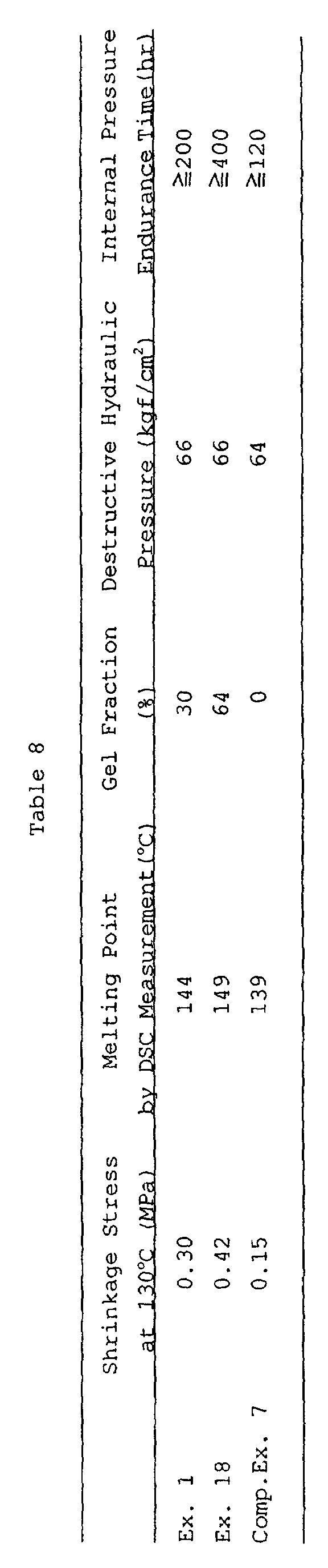
| Destructive Hydraulic Pressure (kgf/cm2) | Internal Pressure Endurance Time (hr) | Modulus of Bending Elasticity (kgf/cm2) | |
| Ex. 19 | 77 | ≧300 | 9000 |
| Ex. 20 | 75 | ≧300 | 12000 |
| Winding Angle | Destructive Internal Pressure (kgf/cm2) | Pulsation Cycles | |
| Ex. 21 | ±85°, ±70° | 92 | 18000 |
| Comp.Ex. 8 | ±80° | 90 | 10000 |
Claims (24)
- A high-pressure composite pipe which comprises a pipe-shaped inner layer made of a synthetic resin, and a reinforcing layer made of a stretched polyolefin resin sheet and wound on an external circumferential surface of the inner layer, with a winding direction of the reinforcing layer being oriented at a predetermined angle relative to an axis of the pipe.
- A high-pressure composite pipe which comprises a pipe-shaped inner layer made of a synthetic resin, a reinforcing layer made of a stretched polyolefin resin sheet and wound on an external circumferential surface of the inner layer, and an outer layer made of a synthetic resin and laminated on the reinforcing layer, with a winding direction of the reinforcing layer being oriented at a predetermined angle relative to an axis of the pipe.
- A high-pressure composite pipe which comprises a pipe-shaped inner layer made of a synthetic resin, a reinforcing layer made of a stretched polyolefin resin sheet and wound on an external circumferential surface of the inner layer, and an adhesion layer having affinity to the inner layer and the reinforcing layer and disposed between the inner layer and the reinforcing layer, with a winding direction of the reinforcing layer being oriented at a predetermined angle relative to an axis of the pipe.
- A high-pressure composite pipe which comprises a pipe-shaped inner layer made of a synthetic resin, a reinforcing layer made of a stretched polyolefin resin sheet and wound on an external circumferential surface of the inner layer, an outer layer made of a synthetic resin and laminated on the reinforcing layer, an inner adhesion layer having affinity to the inner layer and the reinforcing layer and disposed between the inner layer and the reinforcing layer, and an outer adhesion layer having affinity to the outer layer and the reinforcing layer and disposed between the outer layer and the reinforcing layer, with a winding direction of the reinforcing layer being oriented at a predetermined angle relative to an axis of the pipe.
- A high-pressure composite pipe which comprises a pipe-shaped inner layer made of a synthetic resin, a first reinforcing layer made of a stretched polyolefin resin sheet and wound in a circumferential direction, and a second reinforcing layer made of a stretched polyolefin resin sheet and laminated along an axis of the pipe, with a winding direction of the first reinforcing layer being oriented at a predetermined angle relative to the axis of the pipe.
- A high-pressure composite pipe which comprises a pipe-shaped inner layer made of a synthetic resin, a reinforcing layer made of a stretched polyolefin resin sheet and wound on an external circumferential surface of the inner layer, an outer layer made of a synthetic resin and laminated on the reinforcing layer, and an insulating layer made of a synthetic resin foam and disposed between the inner layer and the reinforcing layer and/or between the outer layer and the reinforcing layer.
- A high-pressure composite pipe according to any of claims 1 to 6, wherein the inner layer is streched in at least one direction of an axial direction and a circumferential direction of the pipe.
- A high-pressure composite pipe according to any of claims 1 to 6, wherein the inner layer, or each of the inner and outer layers, comprises a polyolefin resin.
- A high-pressure composite pipe according to any of claims 1 to 6, which comprises a pipe-shaped inner layer made of a synthetic resin, a reinforcing layer made of a stretched polyolefin resin sheet and wound on an external circumferential surface of the inner layer, and an outer layer made of a synthetic resin and laminated on the reinforcing layer, wherein at least one of the inner layer and the outer layer comprises a synthetic resin foam.
- A high-pressure composite pipe according to any of claims 1 to 6, wherein at least one of the inner layer and the outer layer includes a plurality of hollow portions which extend along an axis of the pipe and which are spaced along a circumference of the pipe at a predetermined distance.
- A high-pressure composite pipe according to any of claims 2, 4 and 6, wherein an external circumferential surface of the outer layer is equipped with a plurality of ribs which project radially relative to an axis of the pipe and which are spaced along the axis at a predetermined distance.
- A high-pressure composite pipe according to any of claims 1 to 6, wherein the stretched polyolefin resin sheet shows a lower modulus of tensile elasticity in a 0-2% strain range than in a 2-5% strain range.
- A high-pressure composite pipe according to any of claims 1 to 6, wherein the winding direction of the reinforcing layer is inclined 30° to 90° relative to the axis of the pipe, and the reinforcing layer is laminated on the inner layer and/or the outer layer at symmetric inclination angles relative to the axis of the pipe.
- A high-pressure composite pipe according to any of claims 1 to 6, wherein a plurality of reinforcing layers are braided.
- A high-pressure composite pipe according to any of claims 1 to 6, wherein the reinforcing layer is laminated on the inner layer and/or the outer layer, in such winding directions that winding angles relative to the axis of the pipe, in absolute value, are varied in the range of 5° to 30°.
- A high-pressure composite pipe according to claim 3 or 4, wherein a material for the adhesion layer is composed of an elastomer with a modulus of tensile elasticity in the range of 100 to 2000 kgf/cm2.
- A high-pressure composite pipe according to claim 3 or 4, wherein a material for the adhesion layer has a crosslinked structure.
- A method for joining high-pressure composite pipes each comprising a pipe-shaped inner layer made of a synthetic resin, a reinforcing layer made of a stretched polyolefin resin sheet and wound on an external circumferential surface of the inner layer, and an outer layer made of a synthetic resin and laminated on the reinforcing layer,
which method comprises the steps of:heating and melting an end of each high-pressure composite pipe,flaring the melted end of each high-pressure composite pipe, with a diameter thereof gradually enlarging toward an end face thereof, andbutting the flared ends of both flared high-pressure composite pipes together and fusing internal circumferential surfaces of their inner layers, with their reinforcing layers being turned outwardly. - A method for joining high-pressure composite pipes according to claim 18, which further comprises the steps of:preparing an annular band which has an annular shape and one or more slits therein, in which band a groove runs circumferentially in the middle of an inner circumferential surface, and round-tipped ridges extend circumferentially along both side edges of the inner circumferential surface,approximately centering the annular band over a fusion point of the high-pressure composite pipes,mounting the annular band in such a manner that the groove can house a bulge which is formed by fusion and protrudes outwardly along the fusion point, and that tips of the ridges can contact, on both sides of the bulge, with external circumferential surfaces of the high-pressure composite pipes, andfastening the annular band.
- A method for joining high-pressure composite. pipes according to claim 18, which further comprises the steps of:approximately centering a heat-shrinkable reinforcing material over the fusion point of the high-pressure composite pipes, andshrinking the reinforcing material by heating.
- A method for joining high-pressure composite pipes according to claim 18, which further comprises the steps of:removing a bulge formed along the fusion point of the high-pressure composite pipes,approximately centering a heat-shrinkable reinforcing material over an area from which the bulge is removed, andshrinking the reinforcing material by heating.
- A method for joining high-pressure composite pipes according to claim 20 or 21, wherein the reinforcing material is a tube-shaped element obtained by integrally winding a stretched polyolefin resin sheet into tubular form.
- A method for joining high-pressure composite pipes according to claim 22, wherein the tube-shaped element is obtained by spirally and integrally winding the stretched polyolefin resin sheet on an external circumferential surface of a core, in a plurality of layers which are oriented in reverse inclination directions from each other; and then removing the core.
- A method for joining high-pressure composite pipes according to claim 20 or 21, wherein the reinforcing material is a tube-shaped element obtained by enlarging a diameter of a thermoplastic resin pipe, such that a resin for reinforcing a joint area of the high-pressure composite pipes and a vicinity thereof is oriented in a circumferential direction.
Applications Claiming Priority (5)
| Application Number | Priority Date | Filing Date | Title |
|---|---|---|---|
| JP28812498 | 1998-10-09 | ||
| JP28812498 | 1998-10-09 | ||
| JP9545199 | 1999-04-01 | ||
| JP9545199 | 1999-04-01 | ||
| PCT/JP1999/005242 WO2000022334A1 (en) | 1998-10-09 | 1999-09-24 | Composite high-pressure pipe and method of joining same |
Publications (3)
| Publication Number | Publication Date |
|---|---|
| EP1130303A1 true EP1130303A1 (en) | 2001-09-05 |
| EP1130303A4 EP1130303A4 (en) | 2004-03-24 |
| EP1130303B1 EP1130303B1 (en) | 2006-10-25 |
Family
ID=26436677
Family Applications (1)
| Application Number | Title | Priority Date | Filing Date |
|---|---|---|---|
| EP99944830A Expired - Lifetime EP1130303B1 (en) | 1998-10-09 | 1999-09-24 | Composite high-pressure pipe |
Country Status (6)
| Country | Link |
|---|---|
| US (2) | US6629547B1 (en) |
| EP (1) | EP1130303B1 (en) |
| JP (1) | JP4163385B2 (en) |
| AT (1) | ATE343751T1 (en) |
| DE (1) | DE69933786T2 (en) |
| WO (1) | WO2000022334A1 (en) |
Cited By (13)
| Publication number | Priority date | Publication date | Assignee | Title |
|---|---|---|---|---|
| WO2004028803A1 (en) * | 2002-09-27 | 2004-04-08 | Lankhorst Indutech B.V. | Method for reinforcing an article |
| WO2004106038A3 (en) * | 2003-05-29 | 2005-03-03 | Basf Ag | Joining of multilayer thermoplastic pipes |
| EP1314923A4 (en) * | 2000-08-29 | 2005-03-23 | Sekisui Chemical Co Ltd | COMPOSITE HIGH PRESSURE TUBE AND METHOD FOR MANUFACTURING THE SAME |
| WO2006021711A1 (en) | 2004-08-06 | 2006-03-02 | Societe Des Fibres De Carbone | Reinforced elongated elements, such as tubes, method and device for producing same and use thereof |
| WO2006047375A1 (en) * | 2004-10-22 | 2006-05-04 | Dow Global Technologies Inc. | Composite pipes and method making same |
| WO2008046611A1 (en) * | 2006-10-21 | 2008-04-24 | Rehau Ag + Co | Plastic composite component comprising two plastic bodies welded together, tool for producing a weld connection between the two plastic bodies and method for producing said weld connection |
| WO2010147887A3 (en) * | 2009-06-14 | 2011-03-31 | Advanced Pipe Services, Llc | Plastic pipe with bell |
| WO2010145795A3 (en) * | 2009-06-16 | 2011-09-15 | Rehau Ag + Co | Method for producing a molded part, and a molded part thus produced |
| AU2008203246B2 (en) * | 2003-06-13 | 2012-04-05 | Underground Solutions, Inc. | Fusion process for conduit |
| CN103112173A (en) * | 2012-12-28 | 2013-05-22 | 江苏金波新材料科技有限公司 | Preparation method of composite fiber-winding reinforcing pipe material |
| EP2978797A4 (en) * | 2013-03-26 | 2016-12-14 | Shawcor Ltd | APPARATUS AND COMPOSITION BASED ON POLYPROPYLENE FOR ENVELOPING PIPE WELDING |
| EP3175977A1 (en) * | 2015-12-03 | 2017-06-07 | ContiTech Schlauch GmbH | Mantle hose |
| GB2596283A (en) * | 2020-06-15 | 2021-12-29 | Stephen Boyce Gerard | Thermoplastic composite pipe |
Families Citing this family (62)
| Publication number | Priority date | Publication date | Assignee | Title |
|---|---|---|---|---|
| JP2002013675A (en) * | 2000-04-28 | 2002-01-18 | Sekisui Chem Co Ltd | Composite high pressure pipe |
| AU2001280861A1 (en) * | 2000-07-28 | 2002-02-13 | Hypercar, Inc. | Process and equipment for manufacture of advanced composite structures |
| JP4465092B2 (en) * | 2000-09-07 | 2010-05-19 | 積水化学工業株式会社 | Composite resin pipe joint structure |
| BE1014145A3 (en) * | 2001-04-27 | 2003-05-06 | Solvay Sociutu Anonyme | REINFORCED TUBE IN PLASTIC MATERIAL AND METHOD FOR MANUFACTURING SAID TUBE. |
| BE1014146A3 (en) * | 2001-04-27 | 2003-05-06 | Solvay Sociutu Anonyme | PROTECTED PLASTIC TUBE AND METHOD FOR MANUFACTURING SAID TUBE. |
| US20040144535A1 (en) * | 2003-01-28 | 2004-07-29 | Halliburton Energy Services, Inc. | Post installation cured braided continuous composite tubular |
| US7842769B1 (en) | 2003-06-13 | 2010-11-30 | Underground Solutions Technologies Group, Inc. | Polyvinyl chloride formulations |
| DE10331061B4 (en) * | 2003-07-09 | 2005-05-19 | Technische Universität Dresden | Annular composite workpieces and cold rolling process for their production |
| US7082998B2 (en) * | 2003-07-30 | 2006-08-01 | Halliburton Energy Services, Inc. | Systems and methods for placing a braided, tubular sleeve in a well bore |
| US7675405B2 (en) * | 2004-09-28 | 2010-03-09 | Siemens Aktiengesellschaft | Method and device for testing the measuring value of at least one level sensor arranged in a fuel tank |
| US20060176650A1 (en) * | 2005-05-09 | 2006-08-10 | Jada Technologies | Flexible armored wiring |
| US20070051418A1 (en) * | 2005-09-02 | 2007-03-08 | Rowles Brian A | Multilayer tubes |
| US20070079884A1 (en) * | 2005-10-12 | 2007-04-12 | Arrowhead Products Corporation | Heat shrunk double wall, self-insulating, lightweight duct |
| US7757718B1 (en) | 2007-06-20 | 2010-07-20 | Bruce Mark H | Polymer reinforcement for a clay pipe joint |
| US20090035459A1 (en) * | 2007-08-03 | 2009-02-05 | Li Victor C | Coated pipe and method using strain-hardening brittle matrix composites |
| US7712575B1 (en) * | 2007-08-29 | 2010-05-11 | Willie L Moore | Spiral cut stethoscope wrap |
| WO2009042132A1 (en) | 2007-09-24 | 2009-04-02 | Cantex, Inc. | Non-metallic raceway for wiring and fiber optic cable and method of forming raceway |
| US8048253B2 (en) * | 2007-09-26 | 2011-11-01 | Fiberforge Corporation | System and method for the rapid, automated creation of advanced composite tailored blanks |
| USD605737S1 (en) * | 2007-10-12 | 2009-12-08 | Neoperl Gmbh | Braided hose |
| US20090101224A1 (en) * | 2007-10-17 | 2009-04-23 | Orion Enterprises, Inc. | Joint and joining method for multilayer composite tubing and fittings |
| US20090107553A1 (en) * | 2007-10-31 | 2009-04-30 | E. I. Du Pont De Nemours And Company | Highly abrasion-resistant terionomer pipe |
| KR100831077B1 (en) * | 2007-12-14 | 2008-05-22 | (주) 아모센스 | Pipe having freeze protection function using strip type planar heating element and manufacturing method thereof |
| AU2009308805B2 (en) * | 2008-10-31 | 2015-08-06 | Performance Materials Na, Inc. | Highly abrasion-resistant polyolefin pipe |
| KR101329678B1 (en) * | 2009-06-22 | 2013-11-14 | 보레알리스 아게 | Chlorine dioxide resistant polyethylene pipes, their preparation and use |
| KR100937735B1 (en) * | 2009-11-02 | 2010-01-21 | 원진테크 주식회사 | Polyvinyl chloride liminate pipe of four layer structure |
| TR201000805A2 (en) * | 2010-02-03 | 2011-08-22 | Kalde Kli̇ma Orta Basinç Fi̇tti̇ngs Ve Valf Sanayi̇ Anoni̇m Şi̇rketi̇ | A sheet for joining pipes and fittings. |
| RU2457388C2 (en) * | 2010-10-07 | 2012-07-27 | Общество с ограниченной ответственностью "Группа ПОЛИМЕРТЕПЛО" (ООО "Группа ПОЛИМЕРТЕПЛО") | Multilayer reinforced polymer pipe and pipe system for water transportation |
| RU2600877C2 (en) * | 2010-12-06 | 2016-10-27 | Н.В. Нютрисиа | Fermented infant formula |
| FI20115062A0 (en) * | 2011-01-24 | 2011-01-24 | Maricap Oy | Transfer tube portion of a pneumatic material transfer system and method for forming a tube connection |
| US9162434B2 (en) | 2011-07-28 | 2015-10-20 | Dieffenbacher GmbH Maschinen-und Anlagenbau | System and method for making advanced composite laminates |
| CN102494238B (en) * | 2011-12-22 | 2015-03-04 | 北京玻钢院复合材料有限公司 | Sandwich composite pipe and rapid forming method thereof |
| CN102518898B (en) * | 2012-01-10 | 2014-05-07 | 哈尔滨斯达维机械制造有限公司 | Reinforced electric hot melting belt and connecting structure and method thereof for connecting reinforced plastic electric hot melting belt with plastic pipeline |
| US10036488B2 (en) * | 2012-04-19 | 2018-07-31 | Composite Fluid Transfer LLC | Method for manufacturing a reinforced composite pipe |
| DE102012208020A1 (en) * | 2012-05-14 | 2013-11-14 | Evonik Industries Ag | Method for producing a heatable tube |
| US10184594B1 (en) | 2012-06-01 | 2019-01-22 | Todd A. Volker | Composite pipe |
| BR112015006632B1 (en) * | 2012-09-28 | 2021-04-13 | Dow Global Technologies Llc | COMPOSITE TUBE |
| US9556857B2 (en) * | 2012-11-07 | 2017-01-31 | The Abell Foundation, Inc. | Ocean thermal energy conversion power plant |
| JP6366611B2 (en) | 2013-03-12 | 2018-08-01 | ディーフェンバッハー ゲゼルシャフト ミット ベシュレンクテル ハフツング マシーネン− ウント アンラーゲンバウDieffenbacher GmbH Maschinen− und Anlagenbau | Method and system for manufacturing advanced composite components |
| US9574349B2 (en) * | 2013-05-13 | 2017-02-21 | Hawkeye Pedershaab Concrete Technologies, Inc. | Post-tensioning concrete pipe wrap |
| US10040888B1 (en) | 2013-06-14 | 2018-08-07 | Cooper-Standard Automotive Inc. | Composition including silane-grafted polyolefin |
| US10100139B2 (en) * | 2013-08-01 | 2018-10-16 | Cooper-Standard Automotive Inc. | Hose, composition including silane-grafted polyolefin, and process of making a hose |
| CN103883805A (en) * | 2014-03-24 | 2014-06-25 | 浙江天井塑业有限公司 | HDPE helical bellows and manufacturing method |
| GB2525453A (en) * | 2014-04-23 | 2015-10-28 | Uponor Innovation Ab | Polyolefin pipe |
| CN111853380A (en) | 2014-07-02 | 2020-10-30 | 库博标准汽车配件有限公司 | Hose, abrasion resistant composition and hose manufacturing process |
| US10077856B2 (en) | 2015-06-05 | 2018-09-18 | Advanced Drainage Systems Inc. | Pipe with an outer wrap |
| US10077857B2 (en) | 2015-06-05 | 2018-09-18 | Advanced Drainage Systems Inc. | Pipe with an outer wrap |
| US9759354B2 (en) | 2015-06-05 | 2017-09-12 | Advanced Drainage Systems, Inc. | Pipe with an outer wrap |
| WO2018107086A1 (en) | 2016-12-10 | 2018-06-14 | Cooper-Standard Automotive Inc. | Combined seals, compositions, and methods of making the same |
| CN106891501A (en) * | 2017-01-22 | 2017-06-27 | 杨明昆 | A kind of new steel mesh plastic composite pipe processing technology |
| US20190049056A1 (en) * | 2017-08-09 | 2019-02-14 | Milliken Infrastructure Solutions, Llc | Method for strengthening a polyethylene tubular member |
| US10344904B2 (en) | 2017-08-09 | 2019-07-09 | Milliken Infrastructure Solutions, Llc | Strengthened polyethylene tubular member |
| EP3665005A1 (en) * | 2017-08-09 | 2020-06-17 | Csc Operating Company, LLC. | Strengthened polyethylene tubular member |
| DE102017217544A1 (en) * | 2017-10-02 | 2019-04-04 | Bänninger Kunststoff-Produkte GmbH | Piping and method of manufacture |
| JP6887209B2 (en) * | 2018-10-04 | 2021-06-16 | 古河電気工業株式会社 | Joining method of composite pipe and composite pipe |
| KR102172252B1 (en) * | 2019-05-23 | 2020-10-30 | 이종희 | Telescopic mast |
| KR102948573B1 (en) * | 2020-07-09 | 2026-04-03 | 현대자동차주식회사 | Method for Manufacturing of the Light Weight Cowl cross bar for vehicle |
| CN112388984B (en) * | 2020-09-23 | 2025-03-28 | 郑州赛福流体技术有限公司 | Hydraulic hose assembly fully automatic crimping production equipment |
| JP7667676B2 (en) * | 2021-03-31 | 2025-04-23 | 積水化学工業株式会社 | Piping Materials |
| US12005630B2 (en) | 2021-09-30 | 2024-06-11 | Composite Fluid Transfer LLC | Method for manufacturing a reinforced composite pipe using compression techniques |
| CN114087432B (en) * | 2021-11-22 | 2026-02-24 | 俞亚军 | Inner-layer rubber outer-layer plastic oil delivery pipe and continuous production composite technology thereof |
| CN116006787B (en) * | 2023-01-03 | 2024-11-22 | 康泰塑胶科技集团有限公司 | A high-pressure resistant reinforced steel wire composite pipe and production method thereof |
| CN116394527B (en) * | 2023-06-08 | 2023-08-22 | 复星科技集团有限公司 | Feeding mechanism of glue injection molding system and glue injection molding system |
Family Cites Families (41)
| Publication number | Priority date | Publication date | Assignee | Title |
|---|---|---|---|---|
| CH347051A (en) * | 1957-03-04 | 1960-06-15 | Abegg & Co Ag | Method for welding pipes made of thermoplastic material and device for carrying out the method |
| JPS5134020Y1 (en) * | 1970-08-06 | 1976-08-23 | ||
| GB1411943A (en) * | 1971-10-12 | 1975-10-29 | Raychem Ltd | Covering methods |
| US3779446A (en) * | 1971-10-13 | 1973-12-18 | J Lemelson | Welding apparatus |
| FR2225681B1 (en) * | 1973-04-13 | 1976-05-21 | Pont A Mousson | |
| SE444060B (en) * | 1975-04-09 | 1986-03-17 | Raychem Corp | DEVICE FOR CONNECTING OR REPAIRING PIPES OR OTHER SUBSTRATES |
| DE2460394C2 (en) * | 1974-12-20 | 1987-03-26 | Hoechst Ag, 6230 Frankfurt | Shrinkable polyethylene terephthalate film and its use |
| US4083106A (en) * | 1976-11-15 | 1978-04-11 | Mcelroy Arthur H | Adjustable polyethylene pipe outside bead remover |
| US4130453A (en) * | 1977-07-28 | 1978-12-19 | The Kendall Company | Pipe coating method and apparatus |
| FR2404477A1 (en) * | 1977-10-03 | 1979-04-27 | Kendall & Co | Cladding cylindrical objects, esp. pipeline sections with insulation - in continuous process densifying and protecting foamed layer surface |
| DE3040279A1 (en) * | 1980-10-25 | 1982-06-16 | Hoechst Ag, 6000 Frankfurt | FOR FOODS, ESPECIALLY SAUSAGE PRODUCTS, TUBULAR SLEEVE SUITABLE WITH A STITCH SEAM, METHOD FOR THEIR PRODUCTION AND THEIR USE FOR THE PRODUCTION OF CURVED OR RING SHAPED SAUSAGES |
| DE3105971A1 (en) * | 1981-02-18 | 1982-08-19 | The Kendall Co., 02101 Boston, Mass. | METHOD FOR COATING TUBES |
| JPS57208216A (en) * | 1981-06-18 | 1982-12-21 | Nippon Telegr & Teleph Corp <Ntt> | Plastic pipe having low coefficient of linear expansion and high modulus of elasticity and manufacture thereof |
| JPS5812780U (en) * | 1981-07-17 | 1983-01-26 | 株式会社 潤工社 | high pressure plastic tube |
| JPS5829617A (en) * | 1981-08-14 | 1983-02-21 | Showa Electric Wire & Cable Co Ltd | Method of welding crosslinked polyethylene pipe |
| JPS5947184U (en) * | 1982-09-20 | 1984-03-29 | 積水化学工業株式会社 | synthetic resin pipe |
| CA1184727A (en) * | 1983-04-27 | 1985-04-02 | Paul E. Kaspe | Method and apparatus for forming a single flange pipe adapter |
| JPS60145836A (en) * | 1984-01-06 | 1985-08-01 | 日東電工株式会社 | Heat-shrinkable article |
| ES8607108A1 (en) * | 1984-04-06 | 1986-06-01 | Raychem Sa Nv | Heat-recoverable article. |
| US5236765A (en) * | 1984-04-06 | 1993-08-17 | Nv Raychem Sa | Heat-recoverable article |
| FI85835C (en) * | 1985-08-06 | 1992-06-10 | Kureha Chemical Ind Co Ltd | Non-smoking synthetic packaging film for food |
| US4874665A (en) * | 1987-01-14 | 1989-10-17 | The Kendall Company | Heat shrinkable wraps |
| JPH0425579Y2 (en) * | 1988-04-14 | 1992-06-18 | ||
| JPH02141447A (en) * | 1988-07-29 | 1990-05-30 | Nippon Steel Corp | Stretched polyethylene for reinforcement |
| JPH074875B2 (en) * | 1990-02-20 | 1995-01-25 | 積水化学工業株式会社 | Method for producing fiber reinforced thermoplastic resin pipe |
| JPH03244527A (en) * | 1990-02-23 | 1991-10-31 | Dai Ichi High Frequency Co Ltd | Melt-sticking method for heat shrinkable coating material |
| JPH044132A (en) * | 1990-04-20 | 1992-01-08 | Sekisui Chem Co Ltd | Manufacture of fiber-reinforced thermoplastic resin pipe |
| JPH0422693U (en) * | 1990-06-18 | 1992-02-25 | ||
| JPH0469227A (en) * | 1990-07-10 | 1992-03-04 | Kubota Corp | Corrugated pipe |
| JPH04160284A (en) * | 1990-10-24 | 1992-06-03 | Shiro Kanao | Hard polyethylene pipe |
| JPH0584847A (en) * | 1991-09-30 | 1993-04-06 | Sekisui Chem Co Ltd | Production of fiber reinforced thermoplastic resin pipe |
| JP3244527B2 (en) | 1992-04-20 | 2002-01-07 | 大日本印刷株式会社 | Vacuum press lamination molding equipment |
| US5302428A (en) * | 1992-09-29 | 1994-04-12 | Shaw Industries Ltd. | Multi-layer wraparound heat shrink sleeve |
| JP3243333B2 (en) | 1993-04-22 | 2002-01-07 | 日精エー・エス・ビー機械株式会社 | Injection stretch blow molding equipment |
| JPH06331066A (en) * | 1993-05-18 | 1994-11-29 | Sekisui Chem Co Ltd | Fluid transport pipe |
| JPH07112485A (en) * | 1993-10-19 | 1995-05-02 | Sekisui Chem Co Ltd | How to connect composite pipes |
| US5537745A (en) * | 1995-01-31 | 1996-07-23 | The Wooster Brush Company | Method and apparatus for making paint roller cover with thermo plastic core |
| SE505932C2 (en) * | 1995-11-30 | 1997-10-27 | Borealis As | Use of cross-linked biaxially oriented polyolefin plastic as material in pressure pipes |
| JPH10146892A (en) * | 1996-11-20 | 1998-06-02 | Sekisui Chem Co Ltd | Fluid transport pipe |
| JPH1190885A (en) * | 1997-09-12 | 1999-04-06 | Mesco Inc | Swollen section cutting hand tool for weld section of resin pipe |
| JPH11101383A (en) * | 1997-09-29 | 1999-04-13 | C I Kasei Co Ltd | Connection structure of polyethylene resin pipe and connection method thereof |
-
1999
- 1999-09-24 US US09/821,466 patent/US6629547B1/en not_active Expired - Fee Related
- 1999-09-24 JP JP2000576203A patent/JP4163385B2/en not_active Expired - Fee Related
- 1999-09-24 AT AT99944830T patent/ATE343751T1/en not_active IP Right Cessation
- 1999-09-24 WO PCT/JP1999/005242 patent/WO2000022334A1/en not_active Ceased
- 1999-09-24 DE DE69933786T patent/DE69933786T2/en not_active Expired - Lifetime
- 1999-09-24 EP EP99944830A patent/EP1130303B1/en not_active Expired - Lifetime
-
2003
- 2003-05-02 US US10/427,900 patent/US7094310B2/en not_active Expired - Fee Related
Cited By (16)
| Publication number | Priority date | Publication date | Assignee | Title |
|---|---|---|---|---|
| EP1314923A4 (en) * | 2000-08-29 | 2005-03-23 | Sekisui Chemical Co Ltd | COMPOSITE HIGH PRESSURE TUBE AND METHOD FOR MANUFACTURING THE SAME |
| WO2004028803A1 (en) * | 2002-09-27 | 2004-04-08 | Lankhorst Indutech B.V. | Method for reinforcing an article |
| WO2004106038A3 (en) * | 2003-05-29 | 2005-03-03 | Basf Ag | Joining of multilayer thermoplastic pipes |
| AU2008203246B2 (en) * | 2003-06-13 | 2012-04-05 | Underground Solutions, Inc. | Fusion process for conduit |
| WO2006021711A1 (en) | 2004-08-06 | 2006-03-02 | Societe Des Fibres De Carbone | Reinforced elongated elements, such as tubes, method and device for producing same and use thereof |
| US8043696B2 (en) | 2004-10-22 | 2011-10-25 | Dow Global Technologies Llc | Microlayer structures and methods |
| WO2006047375A1 (en) * | 2004-10-22 | 2006-05-04 | Dow Global Technologies Inc. | Composite pipes and method making same |
| WO2006091245A3 (en) * | 2004-10-22 | 2007-01-04 | Dow Global Technologies Inc | Plastic composite articles and methods of making same |
| US7887660B2 (en) | 2004-10-22 | 2011-02-15 | Dow Global Technologies Inc. | Composite pipes and method making same |
| WO2008046611A1 (en) * | 2006-10-21 | 2008-04-24 | Rehau Ag + Co | Plastic composite component comprising two plastic bodies welded together, tool for producing a weld connection between the two plastic bodies and method for producing said weld connection |
| WO2010147887A3 (en) * | 2009-06-14 | 2011-03-31 | Advanced Pipe Services, Llc | Plastic pipe with bell |
| WO2010145795A3 (en) * | 2009-06-16 | 2011-09-15 | Rehau Ag + Co | Method for producing a molded part, and a molded part thus produced |
| CN103112173A (en) * | 2012-12-28 | 2013-05-22 | 江苏金波新材料科技有限公司 | Preparation method of composite fiber-winding reinforcing pipe material |
| EP2978797A4 (en) * | 2013-03-26 | 2016-12-14 | Shawcor Ltd | APPARATUS AND COMPOSITION BASED ON POLYPROPYLENE FOR ENVELOPING PIPE WELDING |
| EP3175977A1 (en) * | 2015-12-03 | 2017-06-07 | ContiTech Schlauch GmbH | Mantle hose |
| GB2596283A (en) * | 2020-06-15 | 2021-12-29 | Stephen Boyce Gerard | Thermoplastic composite pipe |
Also Published As
| Publication number | Publication date |
|---|---|
| US20040007279A1 (en) | 2004-01-15 |
| JP4163385B2 (en) | 2008-10-08 |
| DE69933786T2 (en) | 2007-09-13 |
| EP1130303A4 (en) | 2004-03-24 |
| ATE343751T1 (en) | 2006-11-15 |
| EP1130303B1 (en) | 2006-10-25 |
| US6629547B1 (en) | 2003-10-07 |
| WO2000022334A1 (en) | 2000-04-20 |
| US7094310B2 (en) | 2006-08-22 |
| DE69933786D1 (en) | 2006-12-07 |
Similar Documents
| Publication | Publication Date | Title |
|---|---|---|
| US7094310B2 (en) | Method for joining high-pressure composite pipes | |
| JPWO2000022334A1 (en) | Composite high-pressure pipe and its joining method | |
| US6688339B2 (en) | Composite high-pressure tube and method of manufacturing the tube | |
| US6016849A (en) | Plastics pipe | |
| US6053214A (en) | Oriented polymeric products | |
| EP3286472B1 (en) | Lightweight, high flow hose assembly and method of manufacture | |
| JP2004527709A (en) | Reinforced plastic pipe and method for manufacturing the pipe | |
| JP2002228080A (en) | Connection method of composite pipe | |
| JP2002333090A (en) | Connection method and reinforcing member for composite high-pressure pipe | |
| JP2002295777A (en) | Composite tube with socket | |
| JP2003103637A (en) | Connection method of composite high pressure pipe | |
| US10344904B2 (en) | Strengthened polyethylene tubular member | |
| JP2002240153A (en) | Method for connecting composite pipes | |
| JP2002295781A (en) | Flange joint | |
| US20190049056A1 (en) | Method for strengthening a polyethylene tubular member | |
| JP2003080601A (en) | Connection method of composite high pressure pipe | |
| US8398908B2 (en) | Plastics pipe | |
| KR200246859Y1 (en) | Heat-shrinkable connecting pipe | |
| JP2002327888A (en) | Electric fusion joint for composite high pressure pipe | |
| JP2000283343A (en) | Composite pipe | |
| JP2002071058A (en) | Composite high pressure pipe | |
| AU749342B2 (en) | Plastics pipe | |
| JP2000283344A (en) | Complex tube | |
| JP2002317895A (en) | Connection method of composite high pressure pipe | |
| WO2019032302A1 (en) | Strengthened polyethylene tubular member |
Legal Events
| Date | Code | Title | Description |
|---|---|---|---|
| PUAI | Public reference made under article 153(3) epc to a published international application that has entered the european phase |
Free format text: ORIGINAL CODE: 0009012 |
|
| 17P | Request for examination filed |
Effective date: 20010417 |
|
| AK | Designated contracting states |
Kind code of ref document: A1 Designated state(s): AT BE CH CY DE DK ES FI FR GB GR IE IT LI LU MC NL PT SE |
|
| RIC1 | Information provided on ipc code assigned before grant |
Ipc: 7B 29C 63/10 B Ipc: 7B 29L 23/00 B Ipc: 7B 29L 9/00 B Ipc: 7B 29C 65/02 B Ipc: 7B 32B 1/08 B Ipc: 7F 16L 47/02 B Ipc: 7F 16L 9/12 A |
|
| RIC1 | Information provided on ipc code assigned before grant |
Ipc: 7B 29C 47/00 - Ipc: 7B 29K 305/00 - Ipc: 7C 08J 5/12 B Ipc: 7B 29C 65/00 B Ipc: 7B 29C 65/20 B Ipc: 7B 29C 63/10 B Ipc: 7B 29L 23/00 B Ipc: 7B 29L 9/00 B Ipc: 7B 29C 65/02 B Ipc: 7B 32B 1/08 B Ipc: 7F 16L 47/02 B Ipc: 7F 16L 9/12 A |
|
| A4 | Supplementary search report drawn up and despatched |
Effective date: 20040206 |
|
| RBV | Designated contracting states (corrected) |
Designated state(s): AT DE FI FR GB NL |
|
| 17Q | First examination report despatched |
Effective date: 20041013 |
|
| GRAP | Despatch of communication of intention to grant a patent |
Free format text: ORIGINAL CODE: EPIDOSNIGR1 |
|
| RTI1 | Title (correction) |
Free format text: COMPOSITE HIGH-PRESSURE PIPE |
|
| GRAS | Grant fee paid |
Free format text: ORIGINAL CODE: EPIDOSNIGR3 |
|
| GRAA | (expected) grant |
Free format text: ORIGINAL CODE: 0009210 |
|
| AK | Designated contracting states |
Kind code of ref document: B1 Designated state(s): AT DE FI FR GB NL |
|
| PG25 | Lapsed in a contracting state [announced via postgrant information from national office to epo] |
Ref country code: NL Free format text: LAPSE BECAUSE OF FAILURE TO SUBMIT A TRANSLATION OF THE DESCRIPTION OR TO PAY THE FEE WITHIN THE PRESCRIBED TIME-LIMIT Effective date: 20061025 Ref country code: FI Free format text: LAPSE BECAUSE OF FAILURE TO SUBMIT A TRANSLATION OF THE DESCRIPTION OR TO PAY THE FEE WITHIN THE PRESCRIBED TIME-LIMIT Effective date: 20061025 Ref country code: AT Free format text: LAPSE BECAUSE OF FAILURE TO SUBMIT A TRANSLATION OF THE DESCRIPTION OR TO PAY THE FEE WITHIN THE PRESCRIBED TIME-LIMIT Effective date: 20061025 |
|
| REG | Reference to a national code |
Ref country code: GB Ref legal event code: FG4D |
|
| REF | Corresponds to: |
Ref document number: 69933786 Country of ref document: DE Date of ref document: 20061207 Kind code of ref document: P |
|
| NLV1 | Nl: lapsed or annulled due to failure to fulfill the requirements of art. 29p and 29m of the patents act | ||
| EN | Fr: translation not filed | ||
| PLBE | No opposition filed within time limit |
Free format text: ORIGINAL CODE: 0009261 |
|
| STAA | Information on the status of an ep patent application or granted ep patent |
Free format text: STATUS: NO OPPOSITION FILED WITHIN TIME LIMIT |
|
| 26N | No opposition filed |
Effective date: 20070726 |
|
| PG25 | Lapsed in a contracting state [announced via postgrant information from national office to epo] |
Ref country code: FR Free format text: LAPSE BECAUSE OF FAILURE TO SUBMIT A TRANSLATION OF THE DESCRIPTION OR TO PAY THE FEE WITHIN THE PRESCRIBED TIME-LIMIT Effective date: 20070608 |
|
| GBPC | Gb: european patent ceased through non-payment of renewal fee |
Effective date: 20070924 |
|
| PG25 | Lapsed in a contracting state [announced via postgrant information from national office to epo] |
Ref country code: GB Free format text: LAPSE BECAUSE OF NON-PAYMENT OF DUE FEES Effective date: 20070924 Ref country code: FR Free format text: LAPSE BECAUSE OF FAILURE TO SUBMIT A TRANSLATION OF THE DESCRIPTION OR TO PAY THE FEE WITHIN THE PRESCRIBED TIME-LIMIT Effective date: 20061025 |
|
| PGFP | Annual fee paid to national office [announced via postgrant information from national office to epo] |
Ref country code: DE Payment date: 20120919 Year of fee payment: 14 |
|
| REG | Reference to a national code |
Ref country code: DE Ref legal event code: R119 Ref document number: 69933786 Country of ref document: DE Effective date: 20140401 |
|
| PG25 | Lapsed in a contracting state [announced via postgrant information from national office to epo] |
Ref country code: DE Free format text: LAPSE BECAUSE OF NON-PAYMENT OF DUE FEES Effective date: 20140401 |