EP1129885B1 - Cruise control system for a vehicle with a multi-functional selector / control device - Google Patents
Cruise control system for a vehicle with a multi-functional selector / control device Download PDFInfo
- Publication number
- EP1129885B1 EP1129885B1 EP01102131A EP01102131A EP1129885B1 EP 1129885 B1 EP1129885 B1 EP 1129885B1 EP 01102131 A EP01102131 A EP 01102131A EP 01102131 A EP01102131 A EP 01102131A EP 1129885 B1 EP1129885 B1 EP 1129885B1
- Authority
- EP
- European Patent Office
- Prior art keywords
- selector
- request
- control element
- setpoint speed
- control
- Prior art date
- Legal status (The legal status is an assumption and is not a legal conclusion. Google has not performed a legal analysis and makes no representation as to the accuracy of the status listed.)
- Expired - Lifetime
Links
Images


Classifications
-
- B—PERFORMING OPERATIONS; TRANSPORTING
- B62—LAND VEHICLES FOR TRAVELLING OTHERWISE THAN ON RAILS
- B62D—MOTOR VEHICLES; TRAILERS
- B62D1/00—Steering controls, i.e. means for initiating a change of direction of the vehicle
- B62D1/02—Steering controls, i.e. means for initiating a change of direction of the vehicle vehicle-mounted
- B62D1/04—Hand wheels
-
- B—PERFORMING OPERATIONS; TRANSPORTING
- B60—VEHICLES IN GENERAL
- B60K—ARRANGEMENT OR MOUNTING OF PROPULSION UNITS OR OF TRANSMISSIONS IN VEHICLES; ARRANGEMENT OR MOUNTING OF PLURAL DIVERSE PRIME-MOVERS IN VEHICLES; AUXILIARY DRIVES FOR VEHICLES; INSTRUMENTATION OR DASHBOARDS FOR VEHICLES; ARRANGEMENTS IN CONNECTION WITH COOLING, AIR INTAKE, GAS EXHAUST OR FUEL SUPPLY OF PROPULSION UNITS IN VEHICLES
- B60K31/00—Vehicle fittings, acting on a single sub-unit only, for automatically controlling vehicle speed, i.e. preventing speed from exceeding an arbitrarily established velocity or maintaining speed at a particular velocity, as selected by the vehicle operator
- B60K31/02—Vehicle fittings, acting on a single sub-unit only, for automatically controlling vehicle speed, i.e. preventing speed from exceeding an arbitrarily established velocity or maintaining speed at a particular velocity, as selected by the vehicle operator including electrically actuated servomechanism including an electric control system or a servomechanism in which the vehicle velocity affecting element is actuated electrically
- B60K31/04—Vehicle fittings, acting on a single sub-unit only, for automatically controlling vehicle speed, i.e. preventing speed from exceeding an arbitrarily established velocity or maintaining speed at a particular velocity, as selected by the vehicle operator including electrically actuated servomechanism including an electric control system or a servomechanism in which the vehicle velocity affecting element is actuated electrically and means for comparing one electrical quantity, e.g. voltage, pulse, waveform, flux, or the like, with another quantity of a like kind, which comparison means is involved in the development of an electrical signal which is fed into the controlling means
- B60K31/042—Vehicle fittings, acting on a single sub-unit only, for automatically controlling vehicle speed, i.e. preventing speed from exceeding an arbitrarily established velocity or maintaining speed at a particular velocity, as selected by the vehicle operator including electrically actuated servomechanism including an electric control system or a servomechanism in which the vehicle velocity affecting element is actuated electrically and means for comparing one electrical quantity, e.g. voltage, pulse, waveform, flux, or the like, with another quantity of a like kind, which comparison means is involved in the development of an electrical signal which is fed into the controlling means where at least one electrical quantity is set by the vehicle operator
-
- B—PERFORMING OPERATIONS; TRANSPORTING
- B60—VEHICLES IN GENERAL
- B60Q—ARRANGEMENT OF SIGNALLING OR LIGHTING DEVICES, THE MOUNTING OR SUPPORTING THEREOF OR CIRCUITS THEREFOR, FOR VEHICLES IN GENERAL
- B60Q1/00—Arrangement of optical signalling or lighting devices, the mounting or supporting thereof or circuits therefor
- B60Q1/0076—Switches therefor
- B60Q1/0082—Switches therefor mounted on the steering wheel
-
- B—PERFORMING OPERATIONS; TRANSPORTING
- B62—LAND VEHICLES FOR TRAVELLING OTHERWISE THAN ON RAILS
- B62D—MOTOR VEHICLES; TRAILERS
- B62D1/00—Steering controls, i.e. means for initiating a change of direction of the vehicle
- B62D1/02—Steering controls, i.e. means for initiating a change of direction of the vehicle vehicle-mounted
- B62D1/04—Hand wheels
- B62D1/046—Adaptations on rotatable parts of the steering wheel for accommodation of switches
Definitions
- the invention relates to a system for speed control for a motor vehicle with a multifunction control element.
- DE 43 38 098 C2 discloses a control lever for a cruise control system of a motor vehicle, which is suitable for driving a plurality of functions.
- the control lever is located in the area of the steering wheel and can be moved to trigger the various functions in the ⁇ x and ⁇ z directions, where in the z direction first functions affect the target speed and in the x direction second functions the recall of a stored target speed and the elimination of the Geschwindigkeltsregelstrom effect.
- the operating lever can be moved in the x and z directions to activate additional functions.
- a disadvantage of the control lever described above, on the one hand that this must be arranged in addition to other control levers on the steering wheel, creating a confusing and sometimes confusing the driver variety of control options.
- the invention is based on the technical problem to provide a system for speed control with a multi-function control, with a clear operation of the various functions of an automatic distance control and / or a cruise control for a motor vehicle are possible.
- a first operating element which is for example marked with a "+” and is referred to below as PLUS, serves to set a desired speed and to change the desired speed in a first direction.
- a second control element which for example carries a "-" and which is referred to below as "MINUS", serves to set or set the desired speed and / or to change the desired speed in a second direction.
- a third operating element referred to below as ON / OFF, is used to activate and deactivate the speed and / or distance control.
- a fourth operating element hereinafter referred to as CANCEL, which serves for suspending the speed control and / or the distance control, wherein an actuation of this operating element triggers a storage of the current setpoint speed.
- RESUME an optionally provided fifth control element
- the Geschwindigkelts- and / or distance control takes the stored value of the target speed as the current target speed.
- the multi-function operating element according to the invention can have a sixth operating element BE with the aid of which the system determines the following time, determined by the system on the basis of different parameters, for a preceding vehicle of the distance control.
- the follow-up time is defined as the time span with which the distance-controlled motor vehicle is to follow a preceding motor vehicle.
- the product of follow-up time and currently driven speed then gives the following distance or setpoint distance.
- the multi-function control element described above is a highly integrated unit with which all functions of both the automatic distance control and the cruise control can be operated. Since both automatic control units affect the driving behavior of the motor vehicle, these functions belong together thematically for a driver. The operability of the multifunction control element according to the invention is promoted, since the driver can set all the different functions of locally combined controls. In addition, since the controls are facing the driver, they may have meaningful labels, so that defies a variety of different functions a safe and comfortable operation of the individual functions using the multi-function control is possible.
- the first operating element PLUS causes a takeover of the currently driven speed of the motor vehicle as a set speed into the system during a first actuation. Furthermore, the first operating element PLUS causes the change in the desired speed in the first direction during a further actuation occurring within a predetermined period of time after a first actuation. This means that for switching on and inertializing the speed control, the first control element can be repeatedly operated once or in short time intervals, for example, to pass the currently driven speed or a contrast increased speed as the target speed of the cruise control.
- the second operating element MINUS then serves in one embodiment by simply or multiple actuation of a change in the desired speed in the negative direction.
- the value of the target speed can be set. It is preferred that the change in the desired speed by pressing the first actuating element PLUS and the second actuating element MINUS takes place in each case by a predetermined speed difference in the positive or negative direction.
- the first actuation of the second control element MINUS, as well as the first actuation of the first control element PLUS, is assigned the assumption of the currently driven speed as the desired speed.
- the set value can automatically be sent to the system if another predetermined time span has elapsed after actuation of one of the two control elements PLUS or MINUS is handed over.
- a seventh operating element which is referred to as a SET, may be provided, by the actuation of which a transfer of the set value of the desired speed is effected by the system.
- the driver can actively decide whether the set value is passed to the system and will be used in the future as a target speed of the cruise control.
- the first control element PLUS and the second control element MINUS are provided only for changing the target speed.
- the actuation of the fifth operating element RESUME causes the change of the target speed with activated cruise control in the opposite direction, but in the same steps as the actuation of the control element SET.
- the multi-function operating element described above is arranged on the edge of a steering wheel impact body of the motor vehicle.
- the operating element is preferably adjacent to another control or Actuating device (horn), wherein the multifunction control element as a module and the further operating device are arranged to be movable relative to each other.
- horn another control or Actuating device
- Fig. 1 the block diagram of a combined speed and distance control is shown.
- the target speed is v request v of a device 13 as the target value is taken over by the regulating device 10, which in the simplest case as a function of the difference between the actual speed v is and the setpoint v soll a manipulated variable I BR and I AN for the braking device 11 and / or the engine 12 of the motor vehicle generated.
- a distance-dependent setpoint speed v is determined and compared with the setpoint speed v desired in the device 13 and the smaller value of the two setpoint speeds is adopted as setpoint value v soll .
- the distance-dependent desired speed v distance is calculated from a follow- up time to the preceding vehicle, which in turn determined at least from the speed of the vehicle ahead. This follow-up time calculated by the system can in turn be changed by the driver within certain limits via an operating element.
- DE 196 24 616 A1 discloses a method for changing the subsequent time.
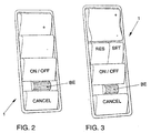
- FIG. 2 shows a first exemplary embodiment of a multifunction operating element 1 according to the invention for operating a combined system of automatic distance control and a speed control for a motor vehicle.
- the topmost control element in FIG. 2 is the above-described first control element PLUS, which is identified by a "+" symbol.
- the second control element MINUS Underneath is the second control element MINUS, which is marked with a "-" symbol.
- the fourth control CANCEL At the lower end of the multifunction control element 1 in Fig. 2 is the fourth control CANCEL, while below the second control element MINUS, the third control element is ON / OFF.
- the sixth operating element BE is arranged between the fourth control element CANCEL and the third operating element ON / OFF.
- the controls PLUS, MINUS, ON / OFF and CANCEL are formed in the present embodiment as a button, which can be operated starting from a monostable position in one direction and return to the monostable position after an operation again. By each pressing an electrical signal can be generated, which are transmitted via - not shown in the drawing - electrical lines with corresponding control units of the automatic distance control and the cruise control.
- the sixth operating element BE is formed in the present embodiment as a thumbwheel, so that by turning this operating element (BE) of the value used for performing the automatic distance control value of the following time can be set, as described for example in DE 196 24 616 A1.
- the thumbwheel is formed in a preferred manner without mechanical stop and generated at a rotary operation per part rotation an electrical signal, so that incrementally the value of the following time can be changed by the system.
- the automatic distance control sets the value of the following time to a predetermined value, which can then be changed by rotating the knurled wheel in one direction or the other.
- a second embodiment of a multi-functional control element according to the invention is shown.
- the fourth control element CANCEL, the third control element ON / OFF and the sixth control element BE are designed in the same way as has been described in detail above with reference to the embodiment shown in FIG.
- the two controls PLUS and MINUS are contrary to the first embodiment, see Fig. 2, not as two separate buttons, but in pairs formed as a rocker switch.
- the rocker switch has a central monostable position, starting from which the upper part as a first control element PLUS and the lower part as a second control element MINUS can be pressed and thus pivoted to perform a corresponding actuation of the respective control element. If the first or second operating element is released after an actuation, the rocker switch returns to the monostable position. Since the first control element PLUS and the second control element MINUS are frequently actuated alternately or subsequently, the configuration as a rocker switch is particularly advantageous.
- a seventh operating element SET is provided according to FIG. 3, which causes an adoption of the set value of the desired speed v desired by the system upon actuation . This allows the above-described adoption of the value to be actively performed by the user.
- a fifth operating element RESUME which activates the deactivated speed control during an actuation and effects a transfer of the stored desired speed v desired by the system.
- the fourth control CANCEL and the fifth control RESUME in alternation be actuated to activate and deactivate the speed control, in each case a storage or readout of the preset value of the desired speed V desire is effected.
- the sixth operating element SET and the seventh operating element RESUME are, as shown in FIG. 3, designed as buttons which are arranged next to one another and occupy only half the width of the other operating elements. Since the two SET and RESUME controls are not required as frequently as the other controls, a smaller attack surface is acceptable, which has a positive effect on the ergonomics and compactness of the multifunction control.
- the setpoint speed v command of the cruise control is then increased or decreased, but at a different interval or font size than when the PLUS and MINUS controls are pressed. If the desired speed v is increased or decreased by the actuation of the PLUS and MINUS controls in increments of 10, the set speed is changed by actuating the RESUME and SET controls in steps of one.
- the set values are displayed on a display, not shown.
- the parameters set with the multifunction control element can be checked by the user.
- a further embodiment of the multi-function control element 1 according to the invention is arranged on a steering wheel 3 of a motor vehicle.
- the multifunction control consists of the controls PLUS, MINUS, SET; RESUME, CANCEL and ON / OFF and the knurling wheel controls BE.
- the function of the individual operating elements is similar to that of the operating elements from the exemplary embodiments of FIGS. 2 and 3.
- the multifunction control element 1 is arranged according to the invention at the edge of the impact body 4 of the steering wheel 3, preferably in the immediate vicinity of the operating or operating device 2 of the horn. To an unwanted actuation of the other control element 2, 1 at exclude the operation of the control element 1, 2, both are mutually movable.
Abstract
Description
Die Erfindung betrifft ein System zur Geschwindigkeitsregelung für ein Kraftfahrzeug mit einem Multifunktions-Bedienelement.The invention relates to a system for speed control for a motor vehicle with a multifunction control element.
Die DE 43 38 098 C2 offenbart einen Bedienhebel für eine Geschwindigkeitsregelanlage eines Kraftfahrzeuges, der zur Ansteuerung einer Mehrzahl von Funktionen geeignet ist. Der Bedienhebel ist im Bereich des Lenkrades angebracht und kann zur Ansteuerung der verschiedenen Funktionen in ± x- und ± z-Richtung tastend bewegt werden, wobei in der z-Richtung erste Funktionen die Sollgeschwindigkeit beeinflussen und in der x-Richtung zweite Funktionen den Abruf einer gespeicherten Sollgeschwindigkeit sowie die Ausschaltung der Geschwindigkeltsregelanlage bewirken. Über definierte Druckpunkte kann der Bedienhebel in x-und z-Richtung tastend bewegt werden, um Zusatzfunktionen anzusteuern. Nachteilig bei dem zuvor beschriebenen Bedienhebel ist einerseits, daß dieser zusätzlich zu weiteren Bedienhebeln am Lenkrad angeordnet werden muß, wodurch eine unübersichtliche und teilweise auch den Fahrer verwirrende Vielzahl von Bedienmöglichkeiten entstehen. Darüber hinaus ist für eine Unterscheidung der verschiedenen Funktionen erforderlich, daß der Fahrer die unterschiedlichen Funktionen den entsprechenden Bedienrichtungen, die zu dem teilweise mehrstufig ausgebildet sind, zuordnet. Die Bedienung der Geschwindigkeitsregelautomatik ist somit gewöhnungsbedürftig und nicht ohne weiteres intuitiv einem Fahrer zugänglich.DE 43 38 098 C2 discloses a control lever for a cruise control system of a motor vehicle, which is suitable for driving a plurality of functions. The control lever is located in the area of the steering wheel and can be moved to trigger the various functions in the ± x and ± z directions, where in the z direction first functions affect the target speed and in the x direction second functions the recall of a stored target speed and the elimination of the Geschwindigkeltsregelanlage effect. Using defined pressure points, the operating lever can be moved in the x and z directions to activate additional functions. A disadvantage of the control lever described above, on the one hand, that this must be arranged in addition to other control levers on the steering wheel, creating a confusing and sometimes confusing the driver variety of control options. In addition, it is necessary for a distinction of the various functions that the driver assigns the different functions to the corresponding operating directions, which are designed to be partially multi-level. The operation of the speed control automatic is therefore getting used to and not easily accessible to a driver intuitively.
Aus den Druckschriften DE 33 31 971 A1, DE G 91 06 579, DE 196 04 351 A1 und DE 197 39 354 A1 sind jeweils Bedienelemente bekannt, die am Lenkrad eines Kraftfahrzeuges im Bereich der Prallplatte angeordnet sind. Mit den Bedienelementen können die verschiedensten Funktionen eines Kraftfahrzeuges gesteuert werden, so bspw. die Lichtanlage, eine Betätigung eines Signalhorns und auch das Ein- und Ausschalten eines Tempomates.From the publications DE 33 31 971 A1, DE G 91 06 579, DE 196 04 351 A1 and DE 197 39 354 A1 controls are known, which are arranged on the steering wheel of a motor vehicle in the baffle plate. With the controls, the various functions of a motor vehicle can be controlled, such as. The lighting system, an operation of a horn and the switching on and off of a cruise control.
Weiterhin sind aus der gattungsgemäßen JP 110 20 506 verschiedene Bedienkonzepte zur Geschwindigkeits- und Abstandsregelung bekannt, deren Bedieneinrichtung an unterschiedlichen Orten im Fahrzeug angeordnet werden kann. Die US 5,382,206 beschreibt ein Verfahren zur Geschwindigkeits- und Abstandsregelung bei dem eine eingestellte Geschwindigkeit gespeichert und später wieder abrufbar ist. Die EP 980 084 hingegen offenbart einen Wippschatter einer Geschwindigkeits- und Abstandsregelung zum Verändern der eingestellten Geschwindigkeit in zwei Richtungen.Furthermore, various operating concepts for speed and distance control are known from the generic JP 110 20 506 whose control device can be arranged at different locations in the vehicle. US 5,382,206 describes a method for speed and distance control in which a set speed is stored and retrievable later. On the other hand, EP 980 084 discloses a rocker of speed and distance control for changing the set speed in two directions.
Der Erfindung liegt das technische Problem zugrunde, ein System zur Geschwindigkeitsregelung mit einem Multifunktions-Bedienelement zu schaffen, mit dem ein übersichtliches Bedienen der verschiedenen Funktionen einer automatischen Abstandsregelung und/oder einer Geschwindigkeitsregelung für ein Kraftfahrzeug ermöglicht werden.The invention is based on the technical problem to provide a system for speed control with a multi-function control, with a clear operation of the various functions of an automatic distance control and / or a cruise control for a motor vehicle are possible.
Das zuvor aufgezeigte technische Problem wird erfindungsgemäß durch ein System zur Geschwindigkeitsregelung mit den Merkmalen des Anspruches 1 gelöst.The technical problem indicated above is achieved according to the invention by a speed control system having the features of
Es sind mindestens drei Bedienelemente vorgesehen, mit denen die verschiedenen Funktionen wie im folgenden einzeln dargestellt betätigt werden können. Ein erstes Bedienelement, das bspw. mit einem "+" gekennzeichnet ist und im folgenden als PLUS bezeichnet wird, dient einem Einstellen einer Sollgeschwindigkeit und einem Verändern der Sollgeschwindigkeit in einer ersten Richtung. Ein zweites Bedienelement, das bspw. ein "-" trägt und das im folgenden mit "MINUS" bezeichnet wird, dient einem Einstellen bzw. Setzen der Sollgeschwindigkeit und/oder einem Verändern der Sollgeschwindigkeit in einer zweiten Richtung. Ein drittes Bedienelement, das im folgenden als ON/OFF bezeichnet wird, dient einem Aktivieren und Deaktivieren der Geschwindigkeits- und/oderAbstandsregelung.There are at least three controls provided with which the various functions as shown below can be operated individually. A first operating element, which is for example marked with a "+" and is referred to below as PLUS, serves to set a desired speed and to change the desired speed in a first direction. A second control element, which for example carries a "-" and which is referred to below as "MINUS", serves to set or set the desired speed and / or to change the desired speed in a second direction. A third operating element, referred to below as ON / OFF, is used to activate and deactivate the speed and / or distance control.
Des weiteren ist ein viertes Bedienelement, im folgenden mit CANCEL bezeichnet, vorgesehen, das zum Aussetzen der Geschwindigkeitsregelung und/oder der Abstandsregelung dient, wobei eine Betätigung dieses Bedienelementes eine Speicherung der aktuellen Sollgeschwindigkeit auslöst. Wird die Geschwindigkeitsregelung und/oder Abstandsregelung durch nochmaliges Betätigen des vierten Bedienelementes oder eines gegebenenfalls vorgesehenen fünften Bedienelementes, im folgenden RESUME genannt, wiederaufgenommen, übernimmt die Geschwindigkelts- und/oder Abstandsregelung den gespeicherten Wert der Sollgeschwindigkeit als aktuelle Sollgeschwindigkeit. Somit findet eine eindeutige Trennung der Funktionen des vierten Bedienelementes CANCEL und des fünften Bedienelementes RESUME statt.Furthermore, a fourth operating element, hereinafter referred to as CANCEL, is provided, which serves for suspending the speed control and / or the distance control, wherein an actuation of this operating element triggers a storage of the current setpoint speed. If the cruise control and / or distance control by repeated actuation of the fourth control element or an optionally provided fifth control element, hereinafter called RESUME resumed, the Geschwindigkelts- and / or distance control takes the stored value of the target speed as the current target speed. Thus, there is a clear separation of the functions of the fourth control element CANCEL and the fifth control element RESUME.
Zusätzlich kann das erfindungsgemäße Multifunktions-Bedienelement ein sechstes Bedienelement BE aufweisen, mit dessen Hilfe die vom System aufgrund unterschiedlicher Parameter ermittelte Folgezeit zu einem vorausfahrenden Fahrzeug der Abstandsregelung manuell verändert wird.In addition, the multi-function operating element according to the invention can have a sixth operating element BE with the aid of which the system determines the following time, determined by the system on the basis of different parameters, for a preceding vehicle of the distance control.
Die Folgezeit ist dabei als die Zeitspanne definiert, mit der das abstandsgeregelte Kraftfahrzeug einem vorausfahrenden Kraftfahrzeug folgen soll. Das Produkt aus Folgezeit und aktuell gefahrener Geschwindigkeit ergibt dann den Folgeabstand bzw. Sollabstand.The follow-up time is defined as the time span with which the distance-controlled motor vehicle is to follow a preceding motor vehicle. The product of follow-up time and currently driven speed then gives the following distance or setpoint distance.
Das zuvor beschriebene Multifunktions-Bedienelement stellt eine hochintegrierte Einheit dar, mit der sämtliche Funktionen sowohl der automatischen Abstandsregelung als auch der Geschwindigkeitsregelung bedient werden können. Da beide automatischen Regeleinheiten das Fahrverhalten des Kraftfahrzeuges beeinflussen, gehören diese Funktionen für einen Fahrer thematisch zusammen. Die Bedienbarkeit des erfindungsgemäßen Multifunktions-Bedienelementes wird gefördert, da der Fahrer sämtliche unterschiedlichen Funktionen an örtlich zusammengefaßten Bedienelementen einstellen kann. Da zudem die Bedienelemente dem Fahrer zugewandt sind, können diese sinnfällige Beschriftungen aufweisen, so daß trotzt einer Vielzahl unterschiedlicher Funktionen ein sicheres und komfortables Bedienen der einzelnen Funktionen mit Hilfe des Multifunktions-Bedienelementes möglich ist.The multi-function control element described above is a highly integrated unit with which all functions of both the automatic distance control and the cruise control can be operated. Since both automatic control units affect the driving behavior of the motor vehicle, these functions belong together thematically for a driver. The operability of the multifunction control element according to the invention is promoted, since the driver can set all the different functions of locally combined controls. In addition, since the controls are facing the driver, they may have meaningful labels, so that defies a variety of different functions a safe and comfortable operation of the individual functions using the multi-function control is possible.
In bevorzugter Weise bewirkt das erste Bedienelement PLUS bei einer ersten Betätigung eine Übernahme der aktuell gefahrenen Geschwindigkeit des Kraftfahrzeuges als Sollgeschwindigkeit in das System. Des weiteren bewirkt das erste Bedienelement PLUS bei einer innerhalb einer vorgegebenen Zeitspanne nach einer ersten Betätigung erfolgenden weiteren Betätigung die Veränderung der Sollgeschwindigkeit in der ersten Richtung. Das bedeutet, daß für ein Einschalten und ein Inertialisieren der Geschwindigkeitsregelung das erste Bedienelement einmal oder in kurzen Zeitabständen mehrfach betätigt werden kann, um bspw. die aktuell gefahrene Geschwindigkeit oder eine demgegenüber vergrößerte Geschwindigkeit als Sollgeschwindigkeit der Geschwindigkeitsregelung zu übergeben.In a preferred manner, the first operating element PLUS causes a takeover of the currently driven speed of the motor vehicle as a set speed into the system during a first actuation. Furthermore, the first operating element PLUS causes the change in the desired speed in the first direction during a further actuation occurring within a predetermined period of time after a first actuation. This means that for switching on and inertializing the speed control, the first control element can be repeatedly operated once or in short time intervals, for example, to pass the currently driven speed or a contrast increased speed as the target speed of the cruise control.
Das zweite Bedienelement MINUS dient in einer Ausführungsform dann durch einfaches oder mehrfaches Betätigen einer Veränderung der Sollgeschwindigkeit in negativer Richtung. Somit kann ausgehend von der aktuell gefahrenen Geschwindigkeit mittels des ersten Bedienelementes PLUS und durch nachfolgende Betätigung des ersten Bedienelementes PLUS oder des zweiten Bedienelementes MINUS der Wert der Sollgeschwindigkeit eingestellt werden. Dabei ist es bevorzugt, daß die Veränderung der Sollgeschwindigkeit durch Betätigen des ersten Betätigungselementes PLUS und des zweiten Betätigungselementes MINUS um jeweils eine vorgegebene Geschwindigkeitsdifferenz in positiver bzw. negativer Richtung erfolgt.The second operating element MINUS then serves in one embodiment by simply or multiple actuation of a change in the desired speed in the negative direction. Thus, starting from the currently driven speed by means of the first control element PLUS and by subsequently actuating the first control element PLUS or the second control element MINUS, the value of the target speed can be set. It is preferred that the change in the desired speed by pressing the first actuating element PLUS and the second actuating element MINUS takes place in each case by a predetermined speed difference in the positive or negative direction.
In einer anderen Ausführungsform ist der ersten Betätigung des zweiten Bedienelementes MINUS ebenso wie der ersten Betätigung des ersten Bedienelementes PLUS die Übernahme der aktuell gefahrenen Geschwindigkeit als Sollgeschwindigkeit zugeordnet.In another embodiment, the first actuation of the second control element MINUS, as well as the first actuation of the first control element PLUS, is assigned the assumption of the currently driven speed as the desired speed.
Entscheidet der Fahrer, daß die durch die Betätigung der beiden Bedienelemente PLUS und MINUS eingestellte Sollgeschwindigkeit richtig ist, so kann der eingestellte Wert, dann, wenn eine weitere vorgegebene Zeitspanne nach einer Betätigung eines der beiden Bedienelemente PLUS oder MINUS verstrichen ist, automatisch an das System übergeben wird. Alternativ dazu kann auch ein siebentes Bedienelement, das als SET bezeichnet wird, vorgesehen sein, durch dessen Betätigung eine Übernahme des eingestellten Wertes der Sollgeschwindigkeit durch das System bewirkt wird. Somit kann der Fahrer aktiv entscheiden, ob der eingestellte Wert an das System übergeben wird und in Zukunft als Sollgeschwindigkeit von der Geschwindigkeitsregelung verwendet wird.If the driver decides that the target speed set by the actuation of the two control elements PLUS and MINUS is correct, then the set value can automatically be sent to the system if another predetermined time span has elapsed after actuation of one of the two control elements PLUS or MINUS is handed over. Alternatively, a seventh operating element, which is referred to as a SET, may be provided, by the actuation of which a transfer of the set value of the desired speed is effected by the system. Thus, the driver can actively decide whether the set value is passed to the system and will be used in the future as a target speed of the cruise control.
In diesem Fall sind das erste Bedienelement PLUS und das zweite Bedienelemente MINUS nur zur Veränderung der Sollgeschwindigkeit vorgesehen.In this case, the first control element PLUS and the second control element MINUS are provided only for changing the target speed.
Weiterhin kann vorgesehen sein, daß bei einer ersten Betätigung des siebenten Bedienelementes SET die aktuell gefahrene Geschwindigkeit des Kraftfahrzeuges als Sollgeschwindigkeit übernommen wird. Bei allen darauf folgenden Betätigungen des Bedienelementes wird dann die Sollgeschwindigkeit in eine erste Richtung verändert. Die Veränderung der Sollgeschwindigkeit erfolgt bei Betätigung des Bedienelementes SET jedoch in anderen Schritten als beim ersten oder zweiten Bedienelement. Zusätzlich kann auch vorgesehen sein, daß die Betätigung des fünften Bedienelementes RESUME die Veränderung der Sollgeschwindigkeit bei aktivierter Geschwindigkeitsregelung in die entgegengesetzte Richtung, jedoch in gleichen Schritten wie die Betätigung des Bedienelementes SET, bewirkt.Furthermore, it can be provided that during a first actuation of the seventh operating element SET, the currently driven speed of the motor vehicle is taken over as the desired speed. For all subsequent actuations of the control element, the setpoint speed is then changed in a first direction. However, the change in the desired speed occurs upon actuation of the operating element SET in other steps than the first or second operating element. In addition, it can also be provided that the actuation of the fifth operating element RESUME causes the change of the target speed with activated cruise control in the opposite direction, but in the same steps as the actuation of the control element SET.
Das zuvor beschriebene Multifunktions-Bedienelement, ist an dem Rand eines Lenkradprallkörpers des Kraftfahrzeuges angeordnet.The multi-function operating element described above is arranged on the edge of a steering wheel impact body of the motor vehicle.
Bei der Zuordnung des Multifunktions-Bedienelementes am Lenkrad des Kraftfahrzeuges ist das Bedienelement vorzugsweise benachbart zu einer weiteren Bedien- oder Betätigungseinrichtung (Hupe), wobei das Multifunktions-Bedienelement als Modul und die weitere Bedieneinrichtung zueinander beweglich angeordnet sind.When assigning the multi-function control element on the steering wheel of the motor vehicle, the operating element is preferably adjacent to another control or Actuating device (horn), wherein the multifunction control element as a module and the further operating device are arranged to be movable relative to each other.
Die Erfindung wird im folgenden anhand von mehreren Ausführungsbeispielen näher erläutert. Die zugehörigen Zeichnungen zeigen:
- Fig. 1
- ein Blockschaltbild einer Geschwindigkeits- und Abstandsregelung,
- Fig. 2
- ein erstes Ausführungsbeispiel eines erfindungsgemäßen Multifunktions-Bedienelementes,
- Fig. 3
- ein zweites Ausführungsbeispiel eines erfindungsgemäßen Multifunktions-Bedienelementes und
- Fig. 4
- ein drittes Ausführungsbeispiel eines erfindungsgemäßen Multifunktions-Bedienelementes.
- Fig. 1
- a block diagram of a speed and distance control,
- Fig. 2
- A first embodiment of a multifunction control element according to the invention,
- Fig. 3
- A second embodiment of a multifunction control element according to the invention and
- Fig. 4
- a third embodiment of a multifunction control element according to the invention.
In Fig. 1 ist das Blockschaltbild einer kombinierten Geschwindigkeits- und Abstandsregelung gezeigt.In Fig. 1, the block diagram of a combined speed and distance control is shown.
Vor Aktivierung der Geschwindigkeits- und Abstandsregelung stellt der Fahrer eine seinen Wünschen entsprechende Sollgeschwindigkeit vwunsch ein. Dies geschieht, indem durch Betätigung eines dafür vorgesehenen Bedienelementes in einem ersten Schritt die momentan gefahrene Geschwindigkeit des Fahrzeuges als Sollgeschwindigkeit vwunsch von der Geschwindigkeits- und Abstandsregelung übernommen wird. Durch die nochmalige Betätigung des selben Bedienelementes oder eines anderen dafür vorgesehenen Bedienelementes kann die Sollgeschwindigkeit vwunsch in Richtung Erhöhung bzw. in Richtung Erniedrigung verändert werden. Ist die Straße vor dem Kraftfahrzeug frei und befindet sich kein Fahrzeug in einem bestimmten geschwindigkeitsabhängigen Abstand vor dem Kraftfahrzeug wird die Sollgeschwindigkeit vwunsch von einer Einrichtung 13 als Sollwert vsoll von der Regeleinrichtung 10 übernommen, die im einfachsten Fall in Abhängigkeit der Differenz zwischen der Istgeschwindigkeit vist und dem Sollwert vsoll eine Stellgröße IBR und IAN für die Bremseinrichtung 11 und/oder die Antriebsmaschine 12 des Kraftfahrzeuges erzeugt.Before activating the speed and distance control system provides the driver with his wishes corresponding nominal speed v request one. This is done by the currently driven speed of the vehicle as desired speed v desired by the speed and distance control is taken over by operating a dedicated control element in a first step. By the repeated actuation of the same control element or another designated control element, the desired speed v wish to be changed in the direction of increase or in the direction of lowering. When the road ahead of the motor vehicle free and there is no vehicle at a certain speed-dependent distance from the motor vehicle, the target speed is v request v of a
Befindet sich vor dem Kraftfahrzeug ein vorausfahrendes Fahrzeug, wird eine abstandsabhängige Sollgeschwindigkeit vabstand ermittelt und in der Einrichtung 13 mit der Sollgeschwindigkeit vwunsch verglichen und der kleinere Wert der beiden Sollgeschwindigkeiten als Sollwert vsoll übernommen. Die abstandsabhängige Sollgeschwindigkeit vabstand berechnet sich dabei aus einer Folgezeit zu dem vorausfahrenden Fahrzeug, die sich wiederum zumindest aus der Geschwindigkeit des vorausfahrenden Fahrzeuges bestimmt. Diese vom System berechnete Folgezeit kann wiederum über ein Bedienelement in bestimmten Grenzen vom Fahrer verändert werden. In diesem Zusammenhang soll auf die DE 196 24 616 A1 verwiesen werden, die ein Verfahren zur Veränderung der Folgezeit offenbart.If there is a preceding vehicle in front of the motor vehicle, a distance-dependent setpoint speed v is determined and compared with the setpoint speed v desired in the
In Fig. 2 ist ein erstes Ausführungsbeispiel eines erfindungsgemäßen Multifunktions-Bedienelementes 1 für eine Bedienung eines kombinierten Systems einer automatischen Abstandsregelung und einer Geschwindigkeitsregelung für ein Kraftfahrzeug gezeigt. Es sind insgesamt fünf Bedienelemente vorgesehen. Das in Fig. 2 oberste Bedienelement ist das zuvor beschriebene erste Bedienelement PLUS, das mit einem "+" -Zeichen gekennzeichnet ist. Darunter befindet sich das zweite Bedienelement MINUS, das mit einem "-" -Zeichen gekennzeichnet ist. Am unteren Ende des Multifunktions-Bedienelementes 1 in Fig. 2 befindet sich das vierte Bedienelement CANCEL, während unterhalb des zweiten Bedienelementes MINUS das dritte Bedienelement ON/OFF angeordnet ist. Weiterhin ist das sechste Bedienelement BE zwischen dem vierten Bedienelement CANCEL und dem dritten Bedienelement ON/OFF angeordnet.FIG. 2 shows a first exemplary embodiment of a
Die Bedienelemente PLUS, MINUS, ON/OFF und CANCEL sind im vorliegenden Ausführungsbeispiel als Taster ausgebildet, die ausgehend von einer monostabilen Lage in einer Richtung betätigt werden können und nach einer Betätigung wieder in die monostabile Lage zurückkehren. Durch jedes Betätigen kann ein elektrisches Signal erzeugt werden, das über - in der Zeichnung nicht dargestellt - elektrische Leitungen mit entsprechenden Steuereinheiten der automatischen Abstandsregelung und der Geschwindigkeitsregelung übertragen werden.The controls PLUS, MINUS, ON / OFF and CANCEL are formed in the present embodiment as a button, which can be operated starting from a monostable position in one direction and return to the monostable position after an operation again. By each pressing an electrical signal can be generated, which are transmitted via - not shown in the drawing - electrical lines with corresponding control units of the automatic distance control and the cruise control.
Das sechste Bedienelement BE ist im vorliegenden Ausführungsbeispiel als Rändelrad ausgebildet, so daß durch ein Drehen dieses Bedienelementes (BE) der für die Durchführung der automatischen Abstandsregelung verwendeten Wertes der Folgezeit eingestellt werden kann, wie beispielsweise in der DE 196 24 616 A1 beschrieben.The sixth operating element BE is formed in the present embodiment as a thumbwheel, so that by turning this operating element (BE) of the value used for performing the automatic distance control value of the following time can be set, as described for example in DE 196 24 616 A1.
Dabei ist das Rändelrad in bevorzugter Weise ohne mechanischen Anschlag ausgebildet und erzeugt bei einer drehenden Betätigung pro Teildrehung ein elektrisches Signal, so daß inkremental der Wert der Folgezeit vom System verändert werden kann. Bei einem Neustart bzw. bei einer neuen Aktivierung der automatischen Abstandsregelung setzt dann das System den Wert der Folgezeit auf einen vorgegebenen Wert, der dann durch eine Drehung des Rändelrades in die eine oder die andere Richtung verändert werden kann. Dadurch wird der Komfort der Betätigung des sechsten Bedienelementes BE erheblich verbessert.In this case, the thumbwheel is formed in a preferred manner without mechanical stop and generated at a rotary operation per part rotation an electrical signal, so that incrementally the value of the following time can be changed by the system. At a restart or at a new activation of the automatic distance control then sets the value of the following time to a predetermined value, which can then be changed by rotating the knurled wheel in one direction or the other. As a result, the comfort of the operation of the sixth operating element BE is considerably improved.
In Fig. 3 ist ein zweites Ausführungsbeispiel eines erfindungsgemäßen Multifunktions-Bedienelementes dargestellt. Das vierte Bedienelement CANCEL, das dritte Bedienelement ON/OFF und das sechste Bedienelement BE sind in gleicher Weise ausgebildet, wie es zuvor anhand des in Fig. 2 dargestellten Ausführungsbeispieles detailliert beschrieben worden ist.In Fig. 3, a second embodiment of a multi-functional control element according to the invention is shown. The fourth control element CANCEL, the third control element ON / OFF and the sixth control element BE are designed in the same way as has been described in detail above with reference to the embodiment shown in FIG.
Die beiden Bedienelemente PLUS und MINUS sind entgegen dem ersten Ausführungsbeispiel, siehe Fig. 2, nicht als zwei separate Taster, sondern paarweise als Wipptaster ausgebildet. Der Wipptaster weist eine mittlere monostabile Lage auf, von der ausgehend der obere Teil als erstes Bedienelement PLUS und der untere Teil als zweites Bedienelement MINUS gedrückt und somit verschwenkt werden kann, um eine entsprechende Betätigung des jeweiligen Bedienelementes auszuführen. Wird das erste oder zweite Bedienelement nach einer Betätigung wieder losgelassen, so kehrt der Wipptaster in die monostabile Lage zurück. Da gerade das erste Bedienelement PLUS und das zweite Bedienelement MINUS häufig abwechselnd oder nachfolgend betätigt werden, ist die Ausgestaltung als Wipptaster besonders vorteilhaft.The two controls PLUS and MINUS are contrary to the first embodiment, see Fig. 2, not as two separate buttons, but in pairs formed as a rocker switch. The rocker switch has a central monostable position, starting from which the upper part as a first control element PLUS and the lower part as a second control element MINUS can be pressed and thus pivoted to perform a corresponding actuation of the respective control element. If the first or second operating element is released after an actuation, the rocker switch returns to the monostable position. Since the first control element PLUS and the second control element MINUS are frequently actuated alternately or subsequently, the configuration as a rocker switch is particularly advantageous.
Zusätzlich zu dem in Fig. 2 dargestellten Ausführungsbeispiel ist gemäß Fig. 3 ein siebentes Bedienelement SET vorgesehen, das bei einer Betätigung eine Übernahme des eingestellten Wertes der Sollgeschwindigkeit vwunsch durch das System bewirkt. Damit kann die oben beschriebenen Übernahme des Wertes aktiv vom Benutzer vorgenommen werden.In addition to the embodiment shown in Fig. 2, a seventh operating element SET is provided according to FIG. 3, which causes an adoption of the set value of the desired speed v desired by the system upon actuation . This allows the above-described adoption of the value to be actively performed by the user.
Weiterhin ist ein fünftes Bedienelement RESUME vorgesehen, das bei einer Betätigung die deaktivierte Geschwindigkeitsregelung aktiviert und eine Übernahme des gespeicherten der Sollgeschwindigkeit vwunsch durch das System bewirkt. Somit können das vierte Bedienelement CANCEL und das fünfte Bedienelement RESUME im Wechsel zueinander betätigt werden, um die Geschwindigkeitsregelung zu aktivieren und zu deaktivieren, wobei jeweils eine Speicherung oder ein Auslesen des voreingestellten Wertes der Sollgeschwindigkeit Vwunsch bewirkt wird.Furthermore, a fifth operating element RESUME is provided, which activates the deactivated speed control during an actuation and effects a transfer of the stored desired speed v desired by the system. Thus, the fourth control CANCEL and the fifth control RESUME in alternation be actuated to activate and deactivate the speed control, in each case a storage or readout of the preset value of the desired speed V desire is effected.
Das sechste Bedienelement SET und das siebte Bedienelement RESUME sind, wie in Fig. 3 dargestellt ist, als Taster ausgebildet, die nebeneinander angeordnet sind und nur die Hälfte der Breite der anderen Bedienelemente einnehmen. Da die beiden Bedienelemente SET und RESUME nicht so häufig wie die anderen Bedienelemente benötigt werden, ist eine geringere Angreiffläche vertretbar, die sich positiv auf die Ergonomie und Kompaktheit des Multifunktions-Bedienelementes auswirkt.The sixth operating element SET and the seventh operating element RESUME are, as shown in FIG. 3, designed as buttons which are arranged next to one another and occupy only half the width of the other operating elements. Since the two SET and RESUME controls are not required as frequently as the other controls, a smaller attack surface is acceptable, which has a positive effect on the ergonomics and compactness of the multifunction control.
Außerdem kann den Bedienelementen RESUME und SET eine weitere Funktion zugeordnet werden. Durch Ihre Betätigung wird dann die Sollgeschwindigkeit vwunsch der Geschwindigkeitsregelung erhöht bzw. erniedrigt, jedoch in einer anderen Intervall- oder Schriftgröße als durch die Betätigung der Bedienelemente PLUS und MINUS. Wenn die Sollgeschwindigkeit vwunsch durch die Betätigung der Bedienelemente PLUS und MINUS in 10er Schritten erhöht bzw. erniedrigt wird, erfolgt die Veränderung der Sollgeschwindigkeit durch die Betätigung der Bedienelemente RESUME und SET in 1er Schritten.In addition, another function can be assigned to the RESUME and SET controls. By pressing this button, the setpoint speed v command of the cruise control is then increased or decreased, but at a different interval or font size than when the PLUS and MINUS controls are pressed. If the desired speed v is increased or decreased by the actuation of the PLUS and MINUS controls in increments of 10, the set speed is changed by actuating the RESUME and SET controls in steps of one.
Zu sämtlichen zuvor beschriebenen Funktionen der automatischen Abstands- und der Geschwindigkeitsregelung werden die eingestellten Werte auf einer nicht dargestellten Anzeige wiedergegeben. Somit können die mit dem Multifunktions-Bedienelement eingestellten Parameter vom Benutzer überprüft werden.For all the above-described functions of the automatic distance control and the speed control, the set values are displayed on a display, not shown. Thus, the parameters set with the multifunction control element can be checked by the user.
In Fig. 4 ist ein weiteres Ausführungsbeispiel des erfindungsgemäßen Multifunktions-Bedienelementes 1 angeordnet auf einem Lenkrad 3 eines Kraftfahrzeuges gezeigt. Das Multifunktions-Bedienelement besteht hier aus den als Taster ausgebildeten Bedienelementen PLUS, MINUS, SET; RESUME, CANCEL und ON/OFF und dem als Rändelrad ausgebildeten Bedienelementen BE. Die Funktion der einzelnen Bedienelemente gleicht denen der Bedienelemente aus den Ausführungsbeispielen der Fig. 2 und Fig. 3.4, a further embodiment of the
Das Multifunktions-Bedienelement 1 ist dabei erfindungsgemäß am Rand des Prallkörpers 4 des Lenkrades 3, vorzugsweise in unmittelbarer Nachbarschaft zu der Bedien- bzw. Betätigungseinrichtung 2 der Hupe angeordnet. Um eine ungewollte Betätigung des jeweils anderen Bedienelementes 2, 1 bei der Betätigung des Bedienelementes 1, 2 auszuschließen, sind beide zueinander beweglich ausgebildet.The
- 11
- Multifunktions-BedienelementMultifunction control element
- 22
- Bedieneinrichtungoperating device
- 33
- Lenkradsteering wheel
- 44
- Prallkörperbaffle
- 1010
- Regeleinrichtungcontrol device
- 1111
- Bremseinrichtungbraking means
- 1212
- Antriebsmaschineprime mover
- 1313
- EinrichtungFacility
- PLUSPLUS
- erstes Bedienelementfirst operating element
- MINUSMINUS
- zweites Bedienelementsecond operating element
- ON/OFFON / OFF
- drittes Bedienelementthird operating element
- CANCELCANCEL
- viertes Bedienelementfourth operating element
- RESUMERESUME
- fünftes Bedienelementfifth control element
- BEBE
- sechste Bedienelementsixth control element
- SETSET
- siebentes Bedienelementseventh operating element
- Vwunsch V wish
- Sollgeschwindigkeittarget speed
- vsoll v should
- Sollwertsetpoint
- vist v is
- IstgeschwindigkeitIs speed
- IBR I BR
- Stellgrößemanipulated variable
- IAN I ON
- Stellgrößemanipulated variable
- vabstand v distance
- abstandsabhängige Sollgeschwindigkeitdistance-dependent setpoint speed
Claims (19)
- Cruise control system for a motor vehicle, the system comprising a multi-functional selector/control element (1) on a steering wheel, the multi-functional selector/control element (1) having• a first selector/control element for setting a setpoint speed (vrequest) and/or changing the setpoint speed (vrequest) in a first direction,characterized in that
the multi-functional selector/control element (1) has• a second selector/control element for setting a setpoint speed (vrequest) and/or changing the setpoint speed (vrequest) in a second direction and• a selector/control element (ON/OFF) for activating and deactivating the cruise control, and• a selector/control element (CANCEL) for cancelling the automatic cruise control,means being provided with which actuation of the selector/control element (CANCEL) for cancelling the automatic cruise control triggers storage of the current setpoint speed (vrequest), and
the selector/control elements for the automatic cruise control being arranged in a highly integrated unit at the edge of the steering wheel impact absorbing body. - Cruise control system according to Claim 1, characterized in that actuation of the selector/control element (CANCEL) for cancelling the automatic cruise control causes the cruise control to be resumed with the stored setpoint speed (vrequest) after the cruise control has been cancelled.
- Cruise control system according to Claim 1 or 2, characterized in that a fifth selector/control element is provided, an at least first actuation of which after the cancelling of the cruise control by the actuation of the selector/control element (CANCEL) for cancelling the automatic cruise control causes the cruise control to be resumed with the stored setpoint speed (vrequest).
- Cruise control system according to one or more of the preceding claims, characterized in that the first selector/control element for setting setpoint speed (vrequest) and/or changing the setpoint speed (vrequest) in a first direction, and the second selector/control element for setting the setpoint speed (vrequest) and/or changing the setpoint speed (vrequest) in a second direction, cause the speed (vact) at which the motor vehicle is currently travelling to be set as a setpoint speed (vrequest) when a first actuation occurs.
- Cruise control system according to Claim 4, characterized in that the first selector/control element for setting the setpoint speed (vrequest) and/or changing the setpoint speed (vrequest) in a first direction, and the second selector/control element for setting the setpoint speed (vrequest) and/or changing the setpoint speed (vrequest) in a second direction, cause the setpoint speed (vrequest) to change when there is a further actuation taking place within a predefined time period after a first actuation.
- Cruise control system according to one or more of the preceding claims, characterized in that a seventh selector/control element for setting the setpoint speed (vrequest) is provided, and the first selector/control element for setting the setpoint speed (vrequest) and/or changing the setpoint speed (vrequest) in a first direction, and the second selector/control element for setting the setpoint speed (vrequest) and/or changing the setpoint speed (vrequest) in a second direction, are provided only for changing the setpoint speed (vrequest).
- Cruise control system according to Claim 6, characterized in that the speed (vact) at which the motor vehicle is currently travelling is transferred as a setpoint speed (vrequest) at least when the seventh selector/control element is first actuated.
- Cruise control system according to one or more of the preceding claims, characterized in that the first selector/control element for setting the setpoint speed (vrequest) and/or changing the setpoint speed (vrequest) in a first direction, and the second selector/control element for setting the setpoint speed (vrequest) and/or changing the setpoint speed (vrequest) in a second direction, cause the value to the changed at equally large intervals when actuation occurs in order to change the value of the setpoint speed (vrequest).
- Cruise control system according to one of Claims 6 to 8, characterized in that the fifth selector/control element causes the setpoint speed (vrequest) to change in a first direction if there is a further actuation occurring within a predefined time period after a first actuation, and the seventh selector/control element causes the setpoint speed (vrequest) to change in a second direction if there is a further actuation occurring within a predefined time period after a first actuation.
- Cruise control system according to Claim 9, characterized in that if there is an actuation in order to change the value of the setpoint speed (vrequest), the fifth selector/control element and the seventh selector/control element cause the value to change at equally large intervals, the intervals differing from the intervals which are provided when the first selector/control element is actuated in order to set the setpoint speed (vrequest) and/or to change the setpoint speed (vrequest) in a first direction, and when the second selector/control element is actuated in order to set the setpoint speed (vrequest) and/or to change the setpoint speed (vrequest) in a second direction.
- Cruise control system according to one or more of the preceding claims, characterized in that the multi-functional selector/control element has at least one selector/control element for setting a setpoint speed (vrequest) and/or changing the setpoint speed (vrequest) in two directions.
- Cruise control system according to one or more of the preceding claims, characterized in that at least some of the selector/control elements (ON/OFF, CANCEL) are embodied as pushbutton keys.
- Cruise control system according to one or more of the preceding claims, characterized in that at least some of the selector/control elements are embodied as rocker switches.
- Cruise control system according to one or more of the preceding claims, characterized in that the multi-functional selector/control element (1) is arranged on the impact absorbing body (4) adjacent to a selector/control device (2).
- Cruise control system according to one or more of the preceding claims, characterized in that the multi-functional selector/control element (1) and the selector/control device (2) are arranged so as to be capable of moving independently of one another.
- Cruise control system according to one or more of the preceding claims, characterized in that the multi-functional selector/control element (1) has selector/control elements for controlling an automatic inter-vehicle distance controller.
- Cruise control system according to Claim 16, characterized in that a sixth selector/control element (BE) is provided for manually changing the value of a following time with respect to a vehicle travelling in front, said value being used to carry out the automatic inter-vehicle distance control.
- Cruise control system according to Claim 17, characterized in that the sixth selector/control element (BE) is embodied as a knurled wheel.
- Cruise control system according to Claim 18, characterized in that the selector/control element (BE) is embodied without a mechanical stop, and in the event of rotating actuation an electrical signal is generated at each part of the rotation.
Applications Claiming Priority (2)
| Application Number | Priority Date | Filing Date | Title |
|---|---|---|---|
| DE10010747A DE10010747A1 (en) | 2000-03-04 | 2000-03-04 | Multifunction operating element for vehicle distance/speed regulating system has elements for setting desired speed/varying desired speed in two directions, activation/deactivation element |
| DE10010747 | 2000-03-04 |
Publications (3)
| Publication Number | Publication Date |
|---|---|
| EP1129885A2 EP1129885A2 (en) | 2001-09-05 |
| EP1129885A3 EP1129885A3 (en) | 2003-10-15 |
| EP1129885B1 true EP1129885B1 (en) | 2006-07-26 |
Family
ID=7633605
Family Applications (1)
| Application Number | Title | Priority Date | Filing Date |
|---|---|---|---|
| EP01102131A Expired - Lifetime EP1129885B1 (en) | 2000-03-04 | 2001-02-01 | Cruise control system for a vehicle with a multi-functional selector / control device |
Country Status (3)
| Country | Link |
|---|---|
| EP (1) | EP1129885B1 (en) |
| AT (1) | ATE334012T1 (en) |
| DE (2) | DE10010747A1 (en) |
Cited By (1)
| Publication number | Priority date | Publication date | Assignee | Title |
|---|---|---|---|---|
| DE102009015800A1 (en) | 2009-04-01 | 2010-10-07 | Volkswagen Ag | Operating process for vehicle steering wheel involves detecting steering angle and releasing or locking functions unit by operating element depending on detected angle |
Families Citing this family (14)
| Publication number | Priority date | Publication date | Assignee | Title |
|---|---|---|---|---|
| DE10219800A1 (en) * | 2002-05-03 | 2003-11-13 | Bosch Gmbh Robert | Method and device for speed control of a motor vehicle and control element |
| DE10261624B4 (en) * | 2002-12-27 | 2014-04-10 | Volkswagen Ag | Method and device for speed and distance control |
| DE10325925B4 (en) * | 2003-06-07 | 2005-11-03 | CNH Österreich GmbH | Method and device for regulating the driving speed of a motor vehicle |
| DE102004052664B3 (en) * | 2004-10-29 | 2006-06-01 | Audi Ag | A speed control apparatus and method for controlling the speed of a vehicle |
| DE102004054635A1 (en) * | 2004-11-12 | 2006-05-24 | Audi Ag | A speed control apparatus and method for controlling a vehicle speed |
| DE102005012715A1 (en) * | 2005-03-19 | 2006-05-04 | Audi Ag | Controller for motor vehicle technical device has scrolling wheel for incremental and decremental variation of parameter, additional actuating element essentially on extension of scrolling wheel rotation axis, immediately adjacent to it |
| DE102005036923A1 (en) * | 2005-08-05 | 2007-02-08 | Bayerische Motoren Werke Ag | Operating device for a driver assistance system for a motor vehicle |
| DE102006027548B4 (en) * | 2006-06-14 | 2014-11-13 | Audi Ag | motor vehicle |
| DE102006060554A1 (en) * | 2006-12-21 | 2008-06-26 | Bayerische Motoren Werke Ag | Steering wheel for a motor vehicle and motor vehicle |
| DE102010009480B4 (en) * | 2010-02-26 | 2021-12-30 | Bayerische Motoren Werke Aktiengesellschaft | Method for storing a callable target speed for an automatic speed control |
| DE102010053481B4 (en) * | 2010-12-04 | 2015-11-05 | Volkswagen Ag | Operating device for the method of a vehicle |
| DE102011110868B4 (en) | 2011-08-17 | 2015-03-05 | Audi Ag | Device for operating a system for automatic distance and / or cruise control and steering wheel with such a device |
| DE102013021011A1 (en) * | 2013-12-13 | 2015-06-18 | Man Truck & Bus Ag | Method for optimizing a driving operation of a motor vehicle |
| DE102016213167A1 (en) | 2016-07-19 | 2018-01-25 | Bayerische Motoren Werke Aktiengesellschaft | Driver assistance system for a motor vehicle for influencing the vehicle speed of the motor vehicle |
Family Cites Families (19)
| Publication number | Priority date | Publication date | Assignee | Title |
|---|---|---|---|---|
| JPS5896142A (en) * | 1981-12-01 | 1983-06-08 | Nippon Denso Co Ltd | Auto-driving apparatus for car |
| DE3331971A1 (en) * | 1983-09-05 | 1985-03-21 | Vaclav 7514 Eggenstein-Leopoldshafen Prech | Motor vehicle steering wheel with integrated instrument panel |
| JPS60222329A (en) * | 1984-04-18 | 1985-11-06 | Mitsubishi Electric Corp | Speed controlling method |
| FR2580240B1 (en) * | 1985-04-10 | 1987-07-10 | Citroen Maxime | GROUPING DEVICE CONSTITUTING A KEYBOARD OF CONTACTORS FOR CONTROLLING EQUIPMENT INSTALLED IN A MOTOR VEHICLE |
| DE9106579U1 (en) * | 1991-05-29 | 1991-10-24 | Schmidt-Beck, Juergen-Robert, 8000 Muenchen, De | |
| JP2887948B2 (en) * | 1991-06-26 | 1999-05-10 | 株式会社デンソー | Vehicle speed control device |
| US5390119A (en) * | 1992-08-31 | 1995-02-14 | Ford Motor Company | Vehicle speed control system with resume/cancel function |
| US5477457A (en) * | 1993-01-12 | 1995-12-19 | Okada; Motohiro | Cruise control system for motorcars |
| DE4338098C2 (en) * | 1993-11-08 | 1996-09-05 | Daimler Benz Ag | Control lever for a cruise control system of a motor vehicle |
| DE19604351B4 (en) * | 1996-02-07 | 2006-03-30 | Marquardt Gmbh | Device for selecting certain functions in a motor vehicle |
| DE19645561A1 (en) * | 1996-11-05 | 1998-05-07 | Scania Cv Ab | Speed regulation switch for speed control system of lorry or passenger coach |
| DE19646104C1 (en) * | 1996-11-08 | 1998-04-02 | Bosch Gmbh Robert | Device for selecting and displaying speeds |
| WO1998050246A1 (en) * | 1997-05-02 | 1998-11-12 | Vertizon Corporation | Programmable cruise control with protection against surge, spin and skid |
| JP3900602B2 (en) * | 1997-07-04 | 2007-04-04 | マツダ株式会社 | Vehicle travel control device |
| DE19739354A1 (en) * | 1997-09-08 | 1999-03-18 | Bosch Gmbh Robert | Steering wheel module of a motor vehicle |
| DE19832870C1 (en) * | 1998-07-22 | 1999-04-08 | Porsche Ag | Operating lever for distance control device in motor vehicle |
| DE19836298A1 (en) * | 1998-08-11 | 2000-02-17 | Bayerische Motoren Werke Ag | Electrical switch combination |
| US5992256A (en) * | 1998-11-27 | 1999-11-30 | Eaton Corporation | Control to suspend automatic upper ratio shifting |
| DE19919457A1 (en) * | 1999-04-29 | 2000-11-02 | Daimler Chrysler Ag | Motor vehicle with a device for regulating speed and a gear selector lever integrates the operating unit for regulating speed into the gear selector lever. |
-
2000
- 2000-03-04 DE DE10010747A patent/DE10010747A1/en not_active Withdrawn
-
2001
- 2001-02-01 AT AT01102131T patent/ATE334012T1/en not_active IP Right Cessation
- 2001-02-01 EP EP01102131A patent/EP1129885B1/en not_active Expired - Lifetime
- 2001-02-01 DE DE50110517T patent/DE50110517D1/en not_active Expired - Lifetime
Cited By (1)
| Publication number | Priority date | Publication date | Assignee | Title |
|---|---|---|---|---|
| DE102009015800A1 (en) | 2009-04-01 | 2010-10-07 | Volkswagen Ag | Operating process for vehicle steering wheel involves detecting steering angle and releasing or locking functions unit by operating element depending on detected angle |
Also Published As
| Publication number | Publication date |
|---|---|
| DE10010747A1 (en) | 2001-09-20 |
| EP1129885A3 (en) | 2003-10-15 |
| ATE334012T1 (en) | 2006-08-15 |
| EP1129885A2 (en) | 2001-09-05 |
| DE50110517D1 (en) | 2006-09-07 |
Similar Documents
| Publication | Publication Date | Title |
|---|---|---|
| EP1129885B1 (en) | Cruise control system for a vehicle with a multi-functional selector / control device | |
| EP2216197B1 (en) | Method for controlling a driver assist system and driver assist system | |
| DE102012002318B4 (en) | Method for operating a motor vehicle and motor vehicle with a driver assistance system | |
| EP2349805B1 (en) | Method for controlling a motor vehicle, and device therefor | |
| EP1485283A1 (en) | Lane-change assistant for motor vehicles | |
| EP1268231B1 (en) | Manoeuvring mode of vehicles having an automated clutch | |
| DE102012002303B4 (en) | Driver assistance system for a motor vehicle, motor vehicle and method for operating a driver assistance system | |
| DE10114470A1 (en) | Motor vehicle lane maintenance and speed regulation device has steering controller switched to standby state by independent main switch, activated by same switch-on signal as speed regulator | |
| DE102012002304A1 (en) | Apparatus for automated driving of a motor vehicle and method for operating a motor vehicle | |
| EP3390188B1 (en) | Operating device for specifying the degree of assistance provided by driver assistance | |
| EP0876936B1 (en) | Input device for a cruise controller with inter- vehicle distance regulator | |
| DE10303611A1 (en) | Speed controller with multiple operating modes | |
| EP1490244B1 (en) | Operating unit for a driver assistance system | |
| WO2023057138A1 (en) | Method for manoeuvring a vehicle on a multi-lane road taking into account behaviour of a user of the vehicle, driver assistance system and vehicle | |
| DE102011101541A1 (en) | Control unit for driver assistance system for setting functions for motion control of motor car, has evaluation unit detecting one of positions, and input for manual change of actual speed entered in respective position of process | |
| EP1943122B1 (en) | Vehicle | |
| WO2004048141A1 (en) | Speed regulator with a plurality of operating modes | |
| DE19947313A1 (en) | Speed limiting device for road vehicle has push-button signal source for activating and de-activating speed limiting device and associated circuit for input of speed reference value | |
| DE102017208993A1 (en) | Distance adjustment by foot pedals | |
| DE102020207313B4 (en) | Driver assistance system for a motor vehicle and motor vehicle with a driver assistance system | |
| DE10043096A1 (en) | Arrangement for motor vehicle speed and distance regulation has control elements for speed and distance regulation formed by rotary and sliding elements respectively | |
| DE102010053481B4 (en) | Operating device for the method of a vehicle | |
| DE19952241A1 (en) | Operating unit for vehicle distance-regulated speed-control system is mounted on automatic gearbox selection lever fitted with multifunction switch(s)for setting gearbox, distance regulation | |
| WO2002006074A1 (en) | Method and device for controlling the speed of a vehicle | |
| DE102013213234A1 (en) | Hand control for a vehicle |
Legal Events
| Date | Code | Title | Description |
|---|---|---|---|
| PUAI | Public reference made under article 153(3) epc to a published international application that has entered the european phase |
Free format text: ORIGINAL CODE: 0009012 |
|
| AK | Designated contracting states |
Kind code of ref document: A2 Designated state(s): AT BE CH CY DE DK ES FI FR GB GR IE IT LI LU MC NL PT SE TR |
|
| AX | Request for extension of the european patent |
Free format text: AL;LT;LV;MK;RO;SI |
|
| PUAL | Search report despatched |
Free format text: ORIGINAL CODE: 0009013 |
|
| AK | Designated contracting states |
Kind code of ref document: A3 Designated state(s): AT BE CH CY DE DK ES FI FR GB GR IE IT LI LU MC NL PT SE TR |
|
| AX | Request for extension of the european patent |
Extension state: AL LT LV MK RO SI |
|
| 17P | Request for examination filed |
Effective date: 20040415 |
|
| AKX | Designation fees paid |
Designated state(s): AT BE CH CY DE DK ES FI FR GB GR IE IT LI LU MC NL PT SE TR |
|
| 17Q | First examination report despatched |
Effective date: 20040629 |
|
| GRAP | Despatch of communication of intention to grant a patent |
Free format text: ORIGINAL CODE: EPIDOSNIGR1 |
|
| RTI1 | Title (correction) |
Free format text: CRUISE CONTROL SYSTEM FOR A VEHICLE WITH A MULTI-FUNCTIONAL SELECTOR / CONTROL DEVICE |
|
| GRAS | Grant fee paid |
Free format text: ORIGINAL CODE: EPIDOSNIGR3 |
|
| GRAA | (expected) grant |
Free format text: ORIGINAL CODE: 0009210 |
|
| AK | Designated contracting states |
Kind code of ref document: B1 Designated state(s): AT BE CH CY DE DK ES FI FR GB GR IE IT LI LU MC NL PT SE TR |
|
| PG25 | Lapsed in a contracting state [announced via postgrant information from national office to epo] |
Ref country code: IT Free format text: LAPSE BECAUSE OF FAILURE TO SUBMIT A TRANSLATION OF THE DESCRIPTION OR TO PAY THE FEE WITHIN THE PRESCRIBED TIME-LIMIT;WARNING: LAPSES OF ITALIAN PATENTS WITH EFFECTIVE DATE BEFORE 2007 MAY HAVE OCCURRED AT ANY TIME BEFORE 2007. THE CORRECT EFFECTIVE DATE MAY BE DIFFERENT FROM THE ONE RECORDED. Effective date: 20060726 Ref country code: NL Free format text: LAPSE BECAUSE OF FAILURE TO SUBMIT A TRANSLATION OF THE DESCRIPTION OR TO PAY THE FEE WITHIN THE PRESCRIBED TIME-LIMIT Effective date: 20060726 Ref country code: FI Free format text: LAPSE BECAUSE OF FAILURE TO SUBMIT A TRANSLATION OF THE DESCRIPTION OR TO PAY THE FEE WITHIN THE PRESCRIBED TIME-LIMIT Effective date: 20060726 Ref country code: IE Free format text: LAPSE BECAUSE OF FAILURE TO SUBMIT A TRANSLATION OF THE DESCRIPTION OR TO PAY THE FEE WITHIN THE PRESCRIBED TIME-LIMIT Effective date: 20060726 |
|
| REG | Reference to a national code |
Ref country code: GB Ref legal event code: FG4D Free format text: NOT ENGLISH |
|
| REG | Reference to a national code |
Ref country code: CH Ref legal event code: EP |
|
| REG | Reference to a national code |
Ref country code: IE Ref legal event code: FG4D Free format text: LANGUAGE OF EP DOCUMENT: GERMAN |
|
| REF | Corresponds to: |
Ref document number: 50110517 Country of ref document: DE Date of ref document: 20060907 Kind code of ref document: P |
|
| PG25 | Lapsed in a contracting state [announced via postgrant information from national office to epo] |
Ref country code: SE Free format text: LAPSE BECAUSE OF FAILURE TO SUBMIT A TRANSLATION OF THE DESCRIPTION OR TO PAY THE FEE WITHIN THE PRESCRIBED TIME-LIMIT Effective date: 20061026 Ref country code: DK Free format text: LAPSE BECAUSE OF FAILURE TO SUBMIT A TRANSLATION OF THE DESCRIPTION OR TO PAY THE FEE WITHIN THE PRESCRIBED TIME-LIMIT Effective date: 20061026 |
|
| PG25 | Lapsed in a contracting state [announced via postgrant information from national office to epo] |
Ref country code: ES Free format text: LAPSE BECAUSE OF FAILURE TO SUBMIT A TRANSLATION OF THE DESCRIPTION OR TO PAY THE FEE WITHIN THE PRESCRIBED TIME-LIMIT Effective date: 20061106 |
|
| GBT | Gb: translation of ep patent filed (gb section 77(6)(a)/1977) |
Effective date: 20061016 |
|
| PG25 | Lapsed in a contracting state [announced via postgrant information from national office to epo] |
Ref country code: PT Free format text: LAPSE BECAUSE OF FAILURE TO SUBMIT A TRANSLATION OF THE DESCRIPTION OR TO PAY THE FEE WITHIN THE PRESCRIBED TIME-LIMIT Effective date: 20061226 |
|
| NLV1 | Nl: lapsed or annulled due to failure to fulfill the requirements of art. 29p and 29m of the patents act | ||
| ET | Fr: translation filed | ||
| REG | Reference to a national code |
Ref country code: IE Ref legal event code: FD4D |
|
| PG25 | Lapsed in a contracting state [announced via postgrant information from national office to epo] |
Ref country code: LI Free format text: LAPSE BECAUSE OF NON-PAYMENT OF DUE FEES Effective date: 20070228 Ref country code: CH Free format text: LAPSE BECAUSE OF NON-PAYMENT OF DUE FEES Effective date: 20070228 Ref country code: MC Free format text: LAPSE BECAUSE OF NON-PAYMENT OF DUE FEES Effective date: 20070228 |
|
| PLBE | No opposition filed within time limit |
Free format text: ORIGINAL CODE: 0009261 |
|
| STAA | Information on the status of an ep patent application or granted ep patent |
Free format text: STATUS: NO OPPOSITION FILED WITHIN TIME LIMIT |
|
| 26N | No opposition filed |
Effective date: 20070427 |
|
| REG | Reference to a national code |
Ref country code: CH Ref legal event code: PL |
|
| BERE | Be: lapsed |
Owner name: VOLKSWAGEN A.G. Effective date: 20070228 |
|
| PG25 | Lapsed in a contracting state [announced via postgrant information from national office to epo] |
Ref country code: BE Free format text: LAPSE BECAUSE OF NON-PAYMENT OF DUE FEES Effective date: 20070228 |
|
| PG25 | Lapsed in a contracting state [announced via postgrant information from national office to epo] |
Ref country code: GR Free format text: LAPSE BECAUSE OF FAILURE TO SUBMIT A TRANSLATION OF THE DESCRIPTION OR TO PAY THE FEE WITHIN THE PRESCRIBED TIME-LIMIT Effective date: 20061027 |
|
| PG25 | Lapsed in a contracting state [announced via postgrant information from national office to epo] |
Ref country code: AT Free format text: LAPSE BECAUSE OF NON-PAYMENT OF DUE FEES Effective date: 20070201 |
|
| PG25 | Lapsed in a contracting state [announced via postgrant information from national office to epo] |
Ref country code: CY Free format text: LAPSE BECAUSE OF FAILURE TO SUBMIT A TRANSLATION OF THE DESCRIPTION OR TO PAY THE FEE WITHIN THE PRESCRIBED TIME-LIMIT Effective date: 20060726 Ref country code: LU Free format text: LAPSE BECAUSE OF NON-PAYMENT OF DUE FEES Effective date: 20070201 |
|
| PG25 | Lapsed in a contracting state [announced via postgrant information from national office to epo] |
Ref country code: TR Free format text: LAPSE BECAUSE OF FAILURE TO SUBMIT A TRANSLATION OF THE DESCRIPTION OR TO PAY THE FEE WITHIN THE PRESCRIBED TIME-LIMIT Effective date: 20060726 |
|
| REG | Reference to a national code |
Ref country code: FR Ref legal event code: PLFP Year of fee payment: 16 |
|
| REG | Reference to a national code |
Ref country code: FR Ref legal event code: PLFP Year of fee payment: 17 |
|
| REG | Reference to a national code |
Ref country code: FR Ref legal event code: PLFP Year of fee payment: 18 |
|
| PGFP | Annual fee paid to national office [announced via postgrant information from national office to epo] |
Ref country code: IT Payment date: 20200224 Year of fee payment: 20 Ref country code: GB Payment date: 20200226 Year of fee payment: 20 Ref country code: DE Payment date: 20200229 Year of fee payment: 20 |
|
| PGFP | Annual fee paid to national office [announced via postgrant information from national office to epo] |
Ref country code: FR Payment date: 20200225 Year of fee payment: 20 |
|
| REG | Reference to a national code |
Ref country code: DE Ref legal event code: R071 Ref document number: 50110517 Country of ref document: DE |
|
| REG | Reference to a national code |
Ref country code: GB Ref legal event code: PE20 Expiry date: 20210131 |
|
| PG25 | Lapsed in a contracting state [announced via postgrant information from national office to epo] |
Ref country code: GB Free format text: LAPSE BECAUSE OF EXPIRATION OF PROTECTION Effective date: 20210131 |
|
| P01 | Opt-out of the competence of the unified patent court (upc) registered |
Effective date: 20230523 |