EP1129809A2 - Driving unit for a pressure application shaft in a welding apparatus - Google Patents
Driving unit for a pressure application shaft in a welding apparatus Download PDFInfo
- Publication number
- EP1129809A2 EP1129809A2 EP01104917A EP01104917A EP1129809A2 EP 1129809 A2 EP1129809 A2 EP 1129809A2 EP 01104917 A EP01104917 A EP 01104917A EP 01104917 A EP01104917 A EP 01104917A EP 1129809 A2 EP1129809 A2 EP 1129809A2
- Authority
- EP
- European Patent Office
- Prior art keywords
- pressure application
- application shaft
- driving unit
- housing
- shaft
- Prior art date
- Legal status (The legal status is an assumption and is not a legal conclusion. Google has not performed a legal analysis and makes no representation as to the accuracy of the status listed.)
- Granted
Links
Images

Classifications
-
- B—PERFORMING OPERATIONS; TRANSPORTING
- B23—MACHINE TOOLS; METAL-WORKING NOT OTHERWISE PROVIDED FOR
- B23K—SOLDERING OR UNSOLDERING; WELDING; CLADDING OR PLATING BY SOLDERING OR WELDING; CUTTING BY APPLYING HEAT LOCALLY, e.g. FLAME CUTTING; WORKING BY LASER BEAM
- B23K20/00—Non-electric welding by applying impact or other pressure, with or without the application of heat, e.g. cladding or plating
-
- B—PERFORMING OPERATIONS; TRANSPORTING
- B23—MACHINE TOOLS; METAL-WORKING NOT OTHERWISE PROVIDED FOR
- B23K—SOLDERING OR UNSOLDERING; WELDING; CLADDING OR PLATING BY SOLDERING OR WELDING; CUTTING BY APPLYING HEAT LOCALLY, e.g. FLAME CUTTING; WORKING BY LASER BEAM
- B23K11/00—Resistance welding; Severing by resistance heating
- B23K11/30—Features relating to electrodes
- B23K11/31—Electrode holders and actuating devices therefor
- B23K11/314—Spot welding guns, e.g. mounted on robots
- B23K11/315—Spot welding guns, e.g. mounted on robots with one electrode moving on a linear path
-
- B—PERFORMING OPERATIONS; TRANSPORTING
- B23—MACHINE TOOLS; METAL-WORKING NOT OTHERWISE PROVIDED FOR
- B23K—SOLDERING OR UNSOLDERING; WELDING; CLADDING OR PLATING BY SOLDERING OR WELDING; CUTTING BY APPLYING HEAT LOCALLY, e.g. FLAME CUTTING; WORKING BY LASER BEAM
- B23K11/00—Resistance welding; Severing by resistance heating
- B23K11/30—Features relating to electrodes
- B23K11/31—Electrode holders and actuating devices therefor
- B23K11/311—Electrode holders and actuating devices therefor the actuating device comprising an electric motor
-
- B—PERFORMING OPERATIONS; TRANSPORTING
- B23—MACHINE TOOLS; METAL-WORKING NOT OTHERWISE PROVIDED FOR
- B23K—SOLDERING OR UNSOLDERING; WELDING; CLADDING OR PLATING BY SOLDERING OR WELDING; CUTTING BY APPLYING HEAT LOCALLY, e.g. FLAME CUTTING; WORKING BY LASER BEAM
- B23K11/00—Resistance welding; Severing by resistance heating
- B23K11/30—Features relating to electrodes
- B23K11/31—Electrode holders and actuating devices therefor
- B23K11/314—Spot welding guns, e.g. mounted on robots
-
- F—MECHANICAL ENGINEERING; LIGHTING; HEATING; WEAPONS; BLASTING
- F16—ENGINEERING ELEMENTS AND UNITS; GENERAL MEASURES FOR PRODUCING AND MAINTAINING EFFECTIVE FUNCTIONING OF MACHINES OR INSTALLATIONS; THERMAL INSULATION IN GENERAL
- F16H—GEARING
- F16H25/00—Gearings comprising primarily only cams, cam-followers and screw-and-nut mechanisms
- F16H25/18—Gearings comprising primarily only cams, cam-followers and screw-and-nut mechanisms for conveying or interconverting oscillating or reciprocating motions
- F16H25/20—Screw mechanisms
- F16H25/22—Screw mechanisms with balls, rollers, or similar members between the co-operating parts; Elements essential to the use of such members
-
- Y—GENERAL TAGGING OF NEW TECHNOLOGICAL DEVELOPMENTS; GENERAL TAGGING OF CROSS-SECTIONAL TECHNOLOGIES SPANNING OVER SEVERAL SECTIONS OF THE IPC; TECHNICAL SUBJECTS COVERED BY FORMER USPC CROSS-REFERENCE ART COLLECTIONS [XRACs] AND DIGESTS
- Y10—TECHNICAL SUBJECTS COVERED BY FORMER USPC
- Y10T—TECHNICAL SUBJECTS COVERED BY FORMER US CLASSIFICATION
- Y10T74/00—Machine element or mechanism
- Y10T74/18—Mechanical movements
- Y10T74/18568—Reciprocating or oscillating to or from alternating rotary
- Y10T74/18576—Reciprocating or oscillating to or from alternating rotary including screw and nut
- Y10T74/18656—Carriage surrounded, guided, and primarily supported by member other than screw [e.g., linear guide, etc.]
Definitions
- the invention relates to a driving unit for pressure application shaft to be driven by a motor in a welding apparatus, wherein a ball screw mechanism for converting rotation of an output shaft of the motor into a reciprocating motion of the pressure application shaft is housed in a housing and a direct acting type rolling guide mechanism is provided between the pressure application shaft for holding the ball screw mechanism and the housing.
- a driving unit for pressure application shaft in a welding gun connected to a wrist of a robot has been conventionally disclosed in, for example, Japanese Patent Laid-Open Publication No. 9-47881, wherein a ball screw mechanism for converting rotation of an output shaft of the motor into a reciprocating motion of the pressure application shaft is housed in a housing and a direct acting type rolling guide mechanism provided between a pressure application shaft member and the housing.
- the pressure application shaft for holding the ball screw mechanism is arranged inside a cylinder constituting the housing, a ball box constituting the direct acting type rolling bearing is fixed to the rear end of the pressure application shaft, and a rail provided with a guide groove at the face confronting the ball box is fixed to the inner wall of the cylinder, whereby these components are assembled inside the cylinder, thereby completing the driving unit for pressure application shaft.
- the driving unit for pressure application shaft comprising the rail, the bearing, the ball screw mechanism, and so forth are assembled in the housing, and an assembling process thereof is troublesome, and hence it is difficult to manufacture a product having high accuracy, arising a problem of high manufacturing cost.
- the invention has been developed to solve the foregoing problem of the prior art, and has an object to provide a driving unit for pressure application shaft in a welding apparatus having components constituting the driving unit for pressure application shaft are integrally assembled with one another, wherein the driving unit for pressure application shaft is integrally fixed to a housing body, thereby easily obtaining the driving unit for pressure application shaft having high accuracy so that the driving unit for pressure application shaft in a welding apparatus with high accuracy at low cost can be obtained.
- the driving unit for pressure application shaft in a welding apparatus to be driven by a motor including a housing 8 for housing therein a ball screw mechanism 11 for converting rotation of an output shaft of a motor 1 into reciprocating motion of a pressure application shaft 7, and a direct acting type rolling guide mechanism 12, 13 provided between a pressure application shaft member and the housing 8, wherein the housing 8 comprises a housing body 9 which is opened at one side in a substantially U-shape in cross section, and a plate 10 for covering the opened portion, and wherein pressure application mechanism members comprise the ball screw mechanism 11, the pressure application shaft member, the direct acting type rolling bearing 12 which is fixed to the pressure application shaft member, and a rail 13 combined with the direct acting type rolling bearing 12, and wherein the pressure application mechanism members are fixed to the housing body 9, and the plate 10 is fixed to the opened portion of the housing body 9.
- the driving unit for pressure application shaft in a welding apparatus is characterized in that a front end of the housing 8 is covered with a front wall 21, and a penetration hole 22 through which the pressure application shaft 7 is inserted is formed on the front wall 21, and no bearing is provided in the penetration hole 22.
- the driving unit for pressure application shaft in a welding apparatus is characterized in that a rear end of a fixed arm is fixed to the U-shaped housing body 9.
- the driving unit for pressure application shaft in a welding apparatus is characterized in that the U-shaped housing body 9 is formed by an extrusion molded member made of aluminum alloy.
- the driving unit for pressure application shaft in a welding apparatus is characterized in that a machining portion for manually rotating a ball screw shaft is formed at the rear end of the ball screw shaft of the ball screw mechanism 11.
- a driving unit for pressure application shaft in a welding apparatus of the invention is described with reference to Figs. 1 to 4.
- a motor for driving a driving unit 2 for pressure application shaft (hereinafter simply referred to as driving unit 2) in a welding apparatus, and a toothed belt 6 is extended between a pulley 4 provided on an output shaft 3 of the motor 1 and a pulley 5 provided on the driving unit 2.
- an electrode for applying a pressure to weld a workpiece in the case of a C-type welding gun
- a connection member (not shown) connected to a gun arm in the case of an X-type welding gun and a work placing table (not shown) in the case of a welding jig.
- the housing 8 Depicted by 8 is a housing for the driving unit 2, and the housing 8 comprises a housing body 9 which is opened at one side in a substantially U-shape in cross section, and a plate 10 for covering the opened portion.
- Pressure application mechanism members comprising the pressure application shaft 7 incorporating the ball screw mechanism 11 therein, a direct acting type rolling bearing 12 fixed to the pressure application shaft 7 and a rail 13 combined with the direct acting type rolling bearing 12 are arranged in the housing 8.
- the housing body 9 is formed by an extrusion molded member made of aluminum alloy.
- the ball screw mechanism 11 comprises a screw shaft 14 and a ball nut 15 engaging with the screw shaft 14, wherein the screw shaft 14 penetrates the ball nut 15, and it is supported by a bearing 16 at the rear portion, and the pulley 5 by which a driving force of the motor 1 is transmitted via the toothed belt 6 is fixed to the rear end of the screw shaft 14.
- a machining portion 30 such as a machining hole or machining projection for manually rotating the screw shaft 14 at the time when the motor 1 is in trouble is formed on the rearmost portion of the screw shaft 14.
- the ball nut 15 is fixed to the angular portion of the pressure application shaft 7 at the rear end thereof by a plurality of bolts 18, 18...at a square flange 17 provided at the rear portion of the ball nut 15.
- the pressure application shaft 7 has projection pieces 19, 19 for holding bolts at the rear end side thereof, and the pressure application shaft 7 and the direct acting type rolling bearing 12 are integrated with each other by bolts 20, 20...which are inserted into the projection pieces 19, 19.
- the pressure application shaft 7 penetrates a penetration hole 22 formed in a front wall 21 for covering the front end of the housing 8 and extended outward the housing 8, and connected to, for example, one gun arm of an X-type electric gun so as to apply a pressure to electrodes attached to the tip ends of the gun arm.
- a bearing is not provided in the penetration hole 22 and the pressure application shaft 7 is inserted into the penetration hole 22 with a gap therebetween, and a scraper 23 and a dust seal 24 are engaged in the gap, and hence the penetration hole 22 is structured as a so-called bearingless one.
- the pressure application shaft 7 forms a movable arm, and the tip end of the fixed arm is attached to the housing body 9.
- the direct acting type rolling bearing 12 is formed substantially in a U-shape, and the rail 13 is arranged at the opened portion side.
- Grooves 26 for accommodating balls 25, 25 are formed on the portion confronting the rail 13 of the direct acting type rolling bearing 12 at the upper and lower surfaces wherein the grooves 26 cooperate together with projections 27 formed on the rail 13.
- the rail 13 is assembled with the direct acting type rolling bearing 12 and fixed to the housing body 9 by bolts 28, 28, so as to function as a stopper for stopping the rotation of the pressure application shaft 7 and as a guide for the reciprocating motion thereof.
- Depicted by 29, 29, are bolts for fixing the plate 10 to the housing body 9.
- the motor 1 In order to reciprocate the pressure application shaft 7 serving as a movable arm of the C-type welding gun, the motor 1 is rotated to rotate the pulley 5 by way of the toothed belt 6 so that the screw shaft 14 is rotated and the ball nut 15 is to be rotated by the rotation of the screw shaft 14.
- the rotating force of the screw shaft 14 is restrained by the direct acting type rolling bearing 12, and it is converted into a reciprocating motion of the ball nut 15, and hence the pressure application shaft 7 incorporating the ball nut 15 at its rear portion performs forward or rearward motion.
- the housing 8 comprises a housing body 9 which is opened at one side in a substantially U-shape in cross section, and a plate 10 for covering the opened portion, and pressure application mechanism members comprised of the pressure application shaft 7 incorporating ball screw mechanism 11 at the rear portion, the pressure application shaft member, the direct acting type rolling bearing 12 which is fixed to the ball screw mechanism 11, and a rail 13 combined with the direct acting type rolling bearing 12 are assembled integrally with one another, and the pressure application mechanism are fixed to the housing body 9, and particularly, the rail 13 and the direct acting type rolling bearing 12 requiring assembly thereof with high precision can be assembled in advance outside the housing 8 so that accurate assembly can be made with ease. Further, since the screw shaft 14,the ball nut 15, the pressure application shaft 7, the direct acting type rolling bearing 12, the rail 13 and so forth can be assembled with one another outside the housing 8, the assembly thereof can be made with very ease.
- the rail 13 can be directly fixed to the housing body 9 without intervening the plate 10, a plate which costs high is not required. Further, since all the parts relating to the accuracy of a central axis in the longitudinal direction through which the pressure application shaft 7 moves needed for a smooth and straight motion of the pressure application shaft 7 are assembled with the housing body 9, and the assembling accuracy is automatically attained by taking care of a mechanical machining accuracy of the housing body 9, and hence the accuracy of the passing core can be made with very ease.
- the front end of the housing 8 is covered with the front wall 21, and the penetration hole 22 through which the pressure application shaft 7 is inserted is formed in the front wall 21 while the penetration hole 22 is formed in a bearingless one, there does not occur inconvenience such as biting of a bearing, even if a sputter is attached to the surface of the pressure application shaft 7. Further, if a bending moment caused by the application of eccentric pressure (caused by eccentric alignment between the axis of electrodes or chip of the welding gun and the axis of the pressure application shaft 7) is applied to the pressure application shaft 7, the direct acting type rolling bearing 12 alone can receive a load so that the influence upon welding can be controlled to the minimum.
- the entire length of the housing becomes short so that the electric gun can be accommodated in compact.
- the housing body 9 is formed by an extrusion molded member made of aluminum alloy, it can be formed with ease so that a material cost and a mechanical machining cost can be sharply reduced.
- the screw shaft 14 is rotated utilizing the machining portion 30 when the motor is in trouble or the like so that the pressure application shaft 7 is returned to a desired position.
- the housing comprises a housing body which is opened at one side in a substantially U-shape in cross section, and a plate for covering the opened portion
- pressure application mechanism members comprise the ball screw mechanism, the pressure application shaft member, the direct acting type rolling bearing which is fixed to the ball screw mechanism, and a rail combined with the direct acting type rolling bearing, and wherein the pressure application mechanism members are fixed to the housing body, and the plate is fixed to the opened portion of the housing body, thereby obtaining the driving unit for pressure application shaft in a welding apparatus capable of assembling the high precious driving unit for pressure application shaft with ease and of being manufactured at low cost.
- a front end of the housing is covered with a front wall, and a penetration hole through which the pressure application shaft is inserted is formed on the front wall, and no bearing is provided in the penetration hole, there does not occur inconvenience such as biting of a bearing. Further, if a bending moment caused by the application of eccentric pressure to the pressure application shaft, the direct acting type rolling bearing alone can receive a load so that the influence upon welding can be controlled to the minimum.
- the U-shaped housing body is formed by an extrusion molded member made of aluminum alloy, it can be formed with ease, thereby providing the driving unit for pressure application shaft in a welding apparatus which can be manufactured at low cost.
- the pressure application shaft is returned to a desired position in response to a case where the motor is in trouble or the like.
Abstract
Description
- The invention relates to a driving unit for pressure application shaft to be driven by a motor in a welding apparatus, wherein a ball screw mechanism for converting rotation of an output shaft of the motor into a reciprocating motion of the pressure application shaft is housed in a housing and a direct acting type rolling guide mechanism is provided between the pressure application shaft for holding the ball screw mechanism and the housing.
- A driving unit for pressure application shaft in a welding gun connected to a wrist of a robot has been conventionally disclosed in, for example, Japanese Patent Laid-Open Publication No. 9-47881, wherein a ball screw mechanism for converting rotation of an output shaft of the motor into a reciprocating motion of the pressure application shaft is housed in a housing and a direct acting type rolling guide mechanism provided between a pressure application shaft member and the housing.
- In this known driving unit for pressure application shaft, the pressure application shaft for holding the ball screw mechanism is arranged inside a cylinder constituting the housing, a ball box constituting the direct acting type rolling bearing is fixed to the rear end of the pressure application shaft, and a rail provided with a guide groove at the face confronting the ball box is fixed to the inner wall of the cylinder, whereby these components are assembled inside the cylinder, thereby completing the driving unit for pressure application shaft.
- However, in the prior art, since the driving unit for pressure application shaft comprising the rail, the bearing, the ball screw mechanism, and so forth are assembled in the housing, and an assembling process thereof is troublesome, and hence it is difficult to manufacture a product having high accuracy, arising a problem of high manufacturing cost.
- The invention has been developed to solve the foregoing problem of the prior art, and has an object to provide a driving unit for pressure application shaft in a welding apparatus having components constituting the driving unit for pressure application shaft are integrally assembled with one another, wherein the driving unit for pressure application shaft is integrally fixed to a housing body, thereby easily obtaining the driving unit for pressure application shaft having high accuracy so that the driving unit for pressure application shaft in a welding apparatus with high accuracy at low cost can be obtained.
- To achieve the above object, the driving unit for pressure application shaft in a welding apparatus to be driven by a motor according to the invention including a
housing 8 for housing therein aball screw mechanism 11 for converting rotation of an output shaft of amotor 1 into reciprocating motion of apressure application shaft 7, and a direct acting typerolling guide mechanism housing 8, wherein thehousing 8 comprises a housing body 9 which is opened at one side in a substantially U-shape in cross section, and aplate 10 for covering the opened portion, and wherein pressure application mechanism members comprise theball screw mechanism 11, the pressure application shaft member, the direct actingtype rolling bearing 12 which is fixed to the pressure application shaft member, and arail 13 combined with the direct actingtype rolling bearing 12, and wherein the pressure application mechanism members are fixed to the housing body 9, and theplate 10 is fixed to the opened portion of the housing body 9. - Further, the driving unit for pressure application shaft in a welding apparatus is characterized in that a front end of the
housing 8 is covered with afront wall 21, and apenetration hole 22 through which thepressure application shaft 7 is inserted is formed on thefront wall 21, and no bearing is provided in thepenetration hole 22. - Further, the driving unit for pressure application shaft in a welding apparatus is characterized in that a rear end of a fixed arm is fixed to the U-shaped housing body 9.
- Further, the driving unit for pressure application shaft in a welding apparatus is characterized in that the U-shaped housing body 9 is formed by an extrusion molded member made of aluminum alloy.
- Further, the driving unit for pressure application shaft in a welding apparatus is characterized in that a machining portion for manually rotating a ball screw shaft is formed at the rear end of the ball screw shaft of the
ball screw mechanism 11. - Fig. 1 is a plan view showing a main portion of a driving unit for pressure application shaft in a welding apparatus according to the invention;
- Fig. 2 is a side view of the driving unit for pressure application shaft in Fig. 1;
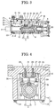
- Fig. 3 is a sectional view of the main portion of the driving unit for pressure application shaft in Fig. 1; and
- Fig. 4 is a sectional view taken along the line A-A in Fig. 3.
-
- A driving unit for pressure application shaft in a welding apparatus of the invention is described with reference to Figs. 1 to 4. In these figures, depicted by 1 is a motor for driving a
driving unit 2 for pressure application shaft (hereinafter simply referred to as driving unit 2) in a welding apparatus, and atoothed belt 6 is extended between apulley 4 provided on anoutput shaft 3 of themotor 1 and apulley 5 provided on thedriving unit 2. Connected to a front end of apressure application shaft 7 arranged on thedriving unit 2 is an electrode (not shown) for applying a pressure to weld a workpiece in the case of a C-type welding gun, a connection member (not shown) connected to a gun arm in the case of an X-type welding gun and a work placing table (not shown) in the case of a welding jig. - Depicted by 8 is a housing for the
driving unit 2, and thehousing 8 comprises a housing body 9 which is opened at one side in a substantially U-shape in cross section, and aplate 10 for covering the opened portion. Pressure application mechanism members comprising thepressure application shaft 7 incorporating theball screw mechanism 11 therein, a direct acting type rolling bearing 12 fixed to thepressure application shaft 7 and arail 13 combined with the direct actingtype rolling bearing 12 are arranged in thehousing 8. The housing body 9 is formed by an extrusion molded member made of aluminum alloy. - The
ball screw mechanism 11 comprises ascrew shaft 14 and aball nut 15 engaging with thescrew shaft 14, wherein thescrew shaft 14 penetrates theball nut 15, and it is supported by abearing 16 at the rear portion, and thepulley 5 by which a driving force of themotor 1 is transmitted via thetoothed belt 6 is fixed to the rear end of thescrew shaft 14. Amachining portion 30 such as a machining hole or machining projection for manually rotating thescrew shaft 14 at the time when themotor 1 is in trouble is formed on the rearmost portion of thescrew shaft 14. Theball nut 15 is fixed to the angular portion of thepressure application shaft 7 at the rear end thereof by a plurality ofbolts square flange 17 provided at the rear portion of theball nut 15. - The
pressure application shaft 7 hasprojection pieces pressure application shaft 7 and the direct actingtype rolling bearing 12 are integrated with each other bybolts projection pieces pressure application shaft 7 penetrates apenetration hole 22 formed in afront wall 21 for covering the front end of thehousing 8 and extended outward thehousing 8, and connected to, for example, one gun arm of an X-type electric gun so as to apply a pressure to electrodes attached to the tip ends of the gun arm. A bearing is not provided in thepenetration hole 22 and thepressure application shaft 7 is inserted into thepenetration hole 22 with a gap therebetween, and a scraper 23 and a dust seal 24 are engaged in the gap, and hence thepenetration hole 22 is structured as a so-called bearingless one. - If the welding apparatus is a C-type electric gun, the
pressure application shaft 7 forms a movable arm, and the tip end of the fixed arm is attached to the housing body 9. - The direct acting
type rolling bearing 12 is formed substantially in a U-shape, and therail 13 is arranged at the opened portion side.Grooves 26 foraccommodating balls rail 13 of the direct acting type rolling bearing 12 at the upper and lower surfaces wherein thegrooves 26 cooperate together withprojections 27 formed on therail 13. - The
rail 13 is assembled with the direct acting type rolling bearing 12 and fixed to the housing body 9 bybolts pressure application shaft 7 and as a guide for the reciprocating motion thereof. Depicted by 29, 29, are bolts for fixing theplate 10 to the housing body 9. - In order to reciprocate the
pressure application shaft 7 serving as a movable arm of the C-type welding gun, themotor 1 is rotated to rotate thepulley 5 by way of thetoothed belt 6 so that thescrew shaft 14 is rotated and theball nut 15 is to be rotated by the rotation of thescrew shaft 14. However, the rotating force of thescrew shaft 14 is restrained by the direct actingtype rolling bearing 12, and it is converted into a reciprocating motion of theball nut 15, and hence thepressure application shaft 7 incorporating theball nut 15 at its rear portion performs forward or rearward motion. - Meanwhile, since the
housing 8 comprises a housing body 9 which is opened at one side in a substantially U-shape in cross section, and aplate 10 for covering the opened portion, and pressure application mechanism members comprised of thepressure application shaft 7 incorporatingball screw mechanism 11 at the rear portion, the pressure application shaft member, the direct actingtype rolling bearing 12 which is fixed to theball screw mechanism 11, and arail 13 combined with the direct actingtype rolling bearing 12 are assembled integrally with one another, and the pressure application mechanism are fixed to the housing body 9, and particularly, therail 13 and the direct acting type rolling bearing 12 requiring assembly thereof with high precision can be assembled in advance outside thehousing 8 so that accurate assembly can be made with ease. Further, since thescrew shaft 14,theball nut 15, thepressure application shaft 7, the direct acting type rolling bearing 12, therail 13 and so forth can be assembled with one another outside thehousing 8, the assembly thereof can be made with very ease. - Further, if the
rail 13 with which the pressure application mechanism members are assembled is fixed to the reference surface which is machined on the inner surface of the housing body 9 by thebolts - Since the
rail 13 can be directly fixed to the housing body 9 without intervening theplate 10, a plate which costs high is not required. Further, since all the parts relating to the accuracy of a central axis in the longitudinal direction through which thepressure application shaft 7 moves needed for a smooth and straight motion of thepressure application shaft 7 are assembled with the housing body 9, and the assembling accuracy is automatically attained by taking care of a mechanical machining accuracy of the housing body 9, and hence the accuracy of the passing core can be made with very ease. - If the front end of the
housing 8 is covered with thefront wall 21, and thepenetration hole 22 through which thepressure application shaft 7 is inserted is formed in thefront wall 21 while thepenetration hole 22 is formed in a bearingless one, there does not occur inconvenience such as biting of a bearing, even if a sputter is attached to the surface of thepressure application shaft 7. Further, if a bending moment caused by the application of eccentric pressure (caused by eccentric alignment between the axis of electrodes or chip of the welding gun and the axis of the pressure application shaft 7) is applied to thepressure application shaft 7, the direct actingtype rolling bearing 12 alone can receive a load so that the influence upon welding can be controlled to the minimum. - Further, if the rear end portion of the fixed arm is attached to the housing body 9, the entire length of the housing becomes short so that the electric gun can be accommodated in compact.
- Further, if the housing body 9 is formed by an extrusion molded member made of aluminum alloy, it can be formed with ease so that a material cost and a mechanical machining cost can be sharply reduced.
- Further, if the
machining portion 30 for manually rotating thescrew shaft 14 is formed on the rear end portion of thescrew shaft 14 of the ball screw mechanism, thescrew shaft 14 is rotated utilizing themachining portion 30 when the motor is in trouble or the like so that thepressure application shaft 7 is returned to a desired position. - According to the invention, since the housing comprises a housing body which is opened at one side in a substantially U-shape in cross section, and a plate for covering the opened portion, and pressure application mechanism members comprise the ball screw mechanism, the pressure application shaft member, the direct acting type rolling bearing which is fixed to the ball screw mechanism, and a rail combined with the direct acting type rolling bearing, and wherein the pressure application mechanism members are fixed to the housing body, and the plate is fixed to the opened portion of the housing body, thereby obtaining the driving unit for pressure application shaft in a welding apparatus capable of assembling the high precious driving unit for pressure application shaft with ease and of being manufactured at low cost.
- Since a front end of the housing is covered with a front wall, and a penetration hole through which the pressure application shaft is inserted is formed on the front wall, and no bearing is provided in the penetration hole, there does not occur inconvenience such as biting of a bearing. Further, if a bending moment caused by the application of eccentric pressure to the pressure application shaft, the direct acting type rolling bearing alone can receive a load so that the influence upon welding can be controlled to the minimum.
- Since a rear end of a fixed arm is fixed to the U-shaped housing body, thereby providing the driving unit for pressure application shaft in a welding apparatus capable of rendering the entire welding apparatus compact.
- Since the U-shaped housing body is formed by an extrusion molded member made of aluminum alloy, it can be formed with ease, thereby providing the driving unit for pressure application shaft in a welding apparatus which can be manufactured at low cost.
- Since a machining portion for manually rotating a ball screw shaft is formed at the rear end of the ball screw shaft of the ball screw mechanism, the pressure application shaft is returned to a desired position in response to a case where the motor is in trouble or the like.
- The features disclosed in the foregoing description, in the claims and/or in the accompanying drawings may, both separately and in any combination thereof, be material for realising the invention in diverse forms thereof.
Claims (5)
- A driving unit (2) for pressure application shaft in a welding apparatus to be driven by a motor (1) including a housing (8) for housing therein a ball screw mechanism (11) for converting rotation of an output shaft of a motor (1) into reciprocating motion of a pressure application shaft (7), and a direct acting type rolling guide mechanism (12, 13) provided between a pressure application shaft member and the housing (8), wherein the housing (8) comprises a housing body (9) which is opened at one side in a substantially U-shape in cross section, and a plate (10) for covering the opened portion, and wherein pressure application mechanism members comprise the ball screw mechanism (11), the pressure application shaft member, the direct acting type rolling bearing (12) which is fixed to the pressure application shaft member, and a rail (13) combined with the direct acting type rolling bearing (12), and wherein the pressure application mechanism members are fixed to the housing body (9), and the plate (10) is fixed to the opened portion of the housing body (9).
- The driving unit (2) for pressure application shaft according to Claim 1, wherein a front end of the housing (8) is covered with a front wall (21), and a penetration hole (22) through which the pressure application shaft (7) is inserted is formed on the front wall (21), and no bearing is provided in the penetration hole (22).
- The driving unit (2) for pressure application shaft according to Claim 1, wherein a rear end of a fixed arm is fixed to the U-shaped housing body (9).
- The driving unit (2) for pressure application shaft according to Claim 1, wherein the U-shaped housing body (9) is formed by an extrusion molded member made of aluminum alloy.
- The driving unit (2) for pressure application shaft according to Claim 1, wherein a machining portion for manually rotating a ball screw shaft is formed at the rear end of the ball screw shaft of the ball screw mechanism (11).
Applications Claiming Priority (2)
| Application Number | Priority Date | Filing Date | Title |
|---|---|---|---|
| JP2000055143A JP4412798B2 (en) | 2000-03-01 | 2000-03-01 | Pressure shaft drive device in welding equipment |
| JP2000055143 | 2000-03-01 |
Publications (3)
| Publication Number | Publication Date |
|---|---|
| EP1129809A2 true EP1129809A2 (en) | 2001-09-05 |
| EP1129809A3 EP1129809A3 (en) | 2002-09-18 |
| EP1129809B1 EP1129809B1 (en) | 2006-12-20 |
Family
ID=18576310
Family Applications (1)
| Application Number | Title | Priority Date | Filing Date |
|---|---|---|---|
| EP01104917A Expired - Lifetime EP1129809B1 (en) | 2000-03-01 | 2001-02-28 | Driving unit for a pressure application shaft in a welding apparatus |
Country Status (7)
| Country | Link |
|---|---|
| US (2) | US20010019038A1 (en) |
| EP (1) | EP1129809B1 (en) |
| JP (1) | JP4412798B2 (en) |
| KR (1) | KR100631261B1 (en) |
| AT (1) | ATE348681T1 (en) |
| DE (1) | DE60125262T2 (en) |
| ES (1) | ES2273757T3 (en) |
Cited By (3)
| Publication number | Priority date | Publication date | Assignee | Title |
|---|---|---|---|---|
| EP1820594A3 (en) * | 2006-02-17 | 2011-08-10 | Dengensha Manufacturing Company Limited | Resistance spot welder |
| CN104033556A (en) * | 2014-06-06 | 2014-09-10 | 嘉善铨盛自动化机械有限公司 | Ball screw locking and locating device |
| CN106960923A (en) * | 2017-04-19 | 2017-07-18 | 朱剑 | A kind of electrokinetic cell safe cap ultrasonic bonding production test line |
Families Citing this family (10)
| Publication number | Priority date | Publication date | Assignee | Title |
|---|---|---|---|---|
| WO2005067674A2 (en) * | 2004-01-08 | 2005-07-28 | Tol-O-Matic, Inc. | Electric actuator |
| DE102005040441B4 (en) * | 2005-08-26 | 2009-01-15 | Airbus Deutschland Gmbh | Linear actuator for remote operation of adjustable components on wind tunnel models |
| US8196484B2 (en) * | 2008-04-18 | 2012-06-12 | Tol-O-Matic, Inc. | Electric actuator |
| DE102008054103A1 (en) * | 2008-10-31 | 2010-05-06 | Friatec Aktiengesellschaft | Component for applications in the service and / or wastewater sector and shut-off valve with such a device |
| JP5399728B2 (en) * | 2009-02-04 | 2014-01-29 | 株式会社電元社製作所 | Direct acting actuator for resistance welding machine |
| US9431868B2 (en) * | 2010-01-19 | 2016-08-30 | Tolomatic, Inc. | Manual override device for an electric actuator and method for use |
| US8701513B2 (en) | 2010-07-14 | 2014-04-22 | Tol-O-Matic, Inc. | Screw driven linear actuator and housing assembly |
| DE102017112448A1 (en) * | 2017-06-06 | 2018-12-06 | Arnold & Shinjo Gmbh & Co. Kg | Apparatus and method for producing a composite component and motor vehicle |
| US11925996B2 (en) | 2018-11-27 | 2024-03-12 | Tolomatic, Inc. | Integrated guide linear actuator system |
| US11754157B2 (en) | 2020-05-20 | 2023-09-12 | Tolomatic, Inc. | Integrated motor linear actuator |
Citations (4)
| Publication number | Priority date | Publication date | Assignee | Title |
|---|---|---|---|---|
| DE3824867C1 (en) * | 1988-07-21 | 1989-10-05 | Josef 7312 Kirchheim De Pradler | Linear drive unit having a multi-element housing |
| JPH09242839A (en) * | 1996-03-07 | 1997-09-16 | Tsubakimoto Chain Co | Whirl-stopping mechanism for screw type linearly operating machine |
| JPH10323764A (en) * | 1997-05-27 | 1998-12-08 | Dengensha Mfg Co Ltd | Motor driven pressurized c gun for spot welding |
| JPH11197842A (en) * | 1998-01-09 | 1999-07-27 | Obara Kk | Pressurizing shaft driving device of motor driven gun |
Family Cites Families (16)
| Publication number | Priority date | Publication date | Assignee | Title |
|---|---|---|---|---|
| US4147073A (en) | 1977-07-01 | 1979-04-03 | Carl Mercier | Garage door opener |
| US4271733A (en) | 1978-09-08 | 1981-06-09 | United Kingdom Atomic Energy Authority | Rotary tools |
| DE3507497C1 (en) | 1985-03-02 | 1986-07-31 | PROMA Produkt- und Marketing-Gesellschaft mbH, 7310 Plochingen | Mechanical linear drive unit |
| US5170675A (en) | 1990-07-30 | 1992-12-15 | Nsk Ltd. | Linear movement table apparatus |
| JPH06170676A (en) | 1992-12-04 | 1994-06-21 | Toshiba Mach Co Ltd | Shaft rotation driving gear for machine tool |
| JP2700621B2 (en) | 1995-02-20 | 1998-01-21 | セイコー精機株式会社 | robot |
| JP3695784B2 (en) | 1995-03-08 | 2005-09-14 | Smc株式会社 | Electric actuator |
| JPH0947881A (en) | 1995-08-03 | 1997-02-18 | Obara Kk | Controller for c type welding gun |
| JP3705641B2 (en) | 1996-01-19 | 2005-10-12 | Smc株式会社 | Actuator |
| JP3899617B2 (en) | 1997-10-20 | 2007-03-28 | Smc株式会社 | Actuator |
| JPH11218204A (en) | 1998-01-29 | 1999-08-10 | Nippon Seiko Kk | Uniaxial table feeder |
| US6337456B1 (en) | 1998-12-16 | 2002-01-08 | Dengensha Manufacturing Company Limited | Welding machine and method for assembling same |
| US6145395A (en) | 1999-01-19 | 2000-11-14 | E-Drive Design, Inc. | Side load compensated linear actuator |
| JP3456696B2 (en) | 1999-06-18 | 2003-10-14 | Obara株式会社 | Pressurized drive for electric welding gun |
| US6223971B1 (en) | 1999-11-24 | 2001-05-01 | Obara Corporation | Driving unit of a welding equipment |
| JP2001170775A (en) | 1999-12-13 | 2001-06-26 | Obara Corp | Drive device for welding equipment |
-
2000
- 2000-03-01 JP JP2000055143A patent/JP4412798B2/en not_active Expired - Lifetime
- 2000-04-25 KR KR1020000021907A patent/KR100631261B1/en active IP Right Grant
-
2001
- 2001-02-28 AT AT01104917T patent/ATE348681T1/en not_active IP Right Cessation
- 2001-02-28 EP EP01104917A patent/EP1129809B1/en not_active Expired - Lifetime
- 2001-02-28 ES ES01104917T patent/ES2273757T3/en not_active Expired - Lifetime
- 2001-02-28 US US09/796,018 patent/US20010019038A1/en not_active Abandoned
- 2001-02-28 DE DE60125262T patent/DE60125262T2/en not_active Expired - Lifetime
-
2003
- 2003-05-13 US US10/436,735 patent/US6718837B2/en not_active Expired - Fee Related
Patent Citations (4)
| Publication number | Priority date | Publication date | Assignee | Title |
|---|---|---|---|---|
| DE3824867C1 (en) * | 1988-07-21 | 1989-10-05 | Josef 7312 Kirchheim De Pradler | Linear drive unit having a multi-element housing |
| JPH09242839A (en) * | 1996-03-07 | 1997-09-16 | Tsubakimoto Chain Co | Whirl-stopping mechanism for screw type linearly operating machine |
| JPH10323764A (en) * | 1997-05-27 | 1998-12-08 | Dengensha Mfg Co Ltd | Motor driven pressurized c gun for spot welding |
| JPH11197842A (en) * | 1998-01-09 | 1999-07-27 | Obara Kk | Pressurizing shaft driving device of motor driven gun |
Non-Patent Citations (3)
| Title |
|---|
| PATENT ABSTRACTS OF JAPAN vol. 1998, no. 01, 30 January 1998 (1998-01-30) & JP 09 242839 A (TSUBAKIMOTO CHAIN CO), 16 September 1997 (1997-09-16) * |
| PATENT ABSTRACTS OF JAPAN vol. 1999, no. 03, 31 March 1999 (1999-03-31) & JP 10 323764 A (DENGENSHA MFG CO LTD), 8 December 1998 (1998-12-08) * |
| PATENT ABSTRACTS OF JAPAN vol. 1999, no. 12, 29 October 1999 (1999-10-29) & JP 11 197842 A (OBARA KK), 27 July 1999 (1999-07-27) * |
Cited By (5)
| Publication number | Priority date | Publication date | Assignee | Title |
|---|---|---|---|---|
| EP1820594A3 (en) * | 2006-02-17 | 2011-08-10 | Dengensha Manufacturing Company Limited | Resistance spot welder |
| EP2452772A1 (en) * | 2006-02-17 | 2012-05-16 | Dengensha Manufacturing Company Limited | Resistance spot welder |
| US8754347B2 (en) | 2006-02-17 | 2014-06-17 | Dengensha Manufacturing Company Limited | Resistance spot welder |
| CN104033556A (en) * | 2014-06-06 | 2014-09-10 | 嘉善铨盛自动化机械有限公司 | Ball screw locking and locating device |
| CN106960923A (en) * | 2017-04-19 | 2017-07-18 | 朱剑 | A kind of electrokinetic cell safe cap ultrasonic bonding production test line |
Also Published As
| Publication number | Publication date |
|---|---|
| EP1129809B1 (en) | 2006-12-20 |
| DE60125262D1 (en) | 2007-02-01 |
| EP1129809A3 (en) | 2002-09-18 |
| JP4412798B2 (en) | 2010-02-10 |
| US6718837B2 (en) | 2004-04-13 |
| DE60125262T2 (en) | 2007-07-05 |
| JP2001246477A (en) | 2001-09-11 |
| ES2273757T3 (en) | 2007-05-16 |
| KR100631261B1 (en) | 2006-10-02 |
| US20030196502A1 (en) | 2003-10-23 |
| KR20010087087A (en) | 2001-09-15 |
| ATE348681T1 (en) | 2007-01-15 |
| US20010019038A1 (en) | 2001-09-06 |
Similar Documents
| Publication | Publication Date | Title |
|---|---|---|
| EP1129809B1 (en) | Driving unit for a pressure application shaft in a welding apparatus | |
| US6845975B2 (en) | Power-driven toggle-lever clamping device | |
| US7322509B2 (en) | Friction stir spot joining device | |
| JP2001525520A (en) | Geared motor unit for driving vehicle equipment without axial play in the power transmission path | |
| WO2002038366A1 (en) | Press | |
| US6628046B2 (en) | Vibration type actuator | |
| US4959989A (en) | Force multiplying press | |
| JP5399728B2 (en) | Direct acting actuator for resistance welding machine | |
| JP3515396B2 (en) | Electric cylinder, welding gun unit using the same, and welding robot | |
| JP3744158B2 (en) | Rotating shaft connection structure | |
| JP3587085B2 (en) | Linear motion guide device with feed screw | |
| JPH11197842A (en) | Pressurizing shaft driving device of motor driven gun | |
| JP3522663B2 (en) | Pressurized shaft drive for electric gun | |
| US20200332870A1 (en) | Ball screw device and steering device | |
| JP2003103375A (en) | Pressurized shaft drive device for electric gun | |
| JP2005282744A (en) | Actuator | |
| KR20080059041A (en) | Driving unit of welding equipment | |
| JP2003014069A (en) | Shaft connecting structure in uniaxial robot | |
| JP3587087B2 (en) | Linear motion guide device with feed screw | |
| EP4151884B1 (en) | Linear electromechanical actuator and method for assembling the output member of such actuator | |
| JP3461968B2 (en) | Linear actuator | |
| JPH073080Y2 (en) | Rack and pinion equipment | |
| JPS62297565A (en) | Ball screw feeder | |
| JPH0141468B2 (en) | ||
| JPH0337871Y2 (en) |
Legal Events
| Date | Code | Title | Description |
|---|---|---|---|
| PUAI | Public reference made under article 153(3) epc to a published international application that has entered the european phase |
Free format text: ORIGINAL CODE: 0009012 |
|
| AK | Designated contracting states |
Kind code of ref document: A2 Designated state(s): AT BE CH CY DE DK ES FI FR GB GR IE IT LI LU MC NL PT SE TR |
|
| AX | Request for extension of the european patent |
Free format text: AL;LT;LV;MK;RO;SI |
|
| PUAL | Search report despatched |
Free format text: ORIGINAL CODE: 0009013 |
|
| AK | Designated contracting states |
Kind code of ref document: A3 Designated state(s): AT BE CH CY DE DK ES FI FR GB GR IE IT LI LU MC NL PT SE TR |
|
| AX | Request for extension of the european patent |
Free format text: AL;LT;LV;MK;RO;SI |
|
| 17P | Request for examination filed |
Effective date: 20030228 |
|
| AKX | Designation fees paid |
Designated state(s): AT BE CH CY DE DK ES FI FR GB GR IE IT LI LU MC NL PT SE TR |
|
| 17Q | First examination report despatched |
Effective date: 20030827 |
|
| GRAP | Despatch of communication of intention to grant a patent |
Free format text: ORIGINAL CODE: EPIDOSNIGR1 |
|
| RIN1 | Information on inventor provided before grant (corrected) |
Inventor name: SASAKI, YOSHIYUKI,C/O OBARA CORPORATION Inventor name: SATO, YOSHIO,C/O OBARA CORPORATION |
|
| GRAS | Grant fee paid |
Free format text: ORIGINAL CODE: EPIDOSNIGR3 |
|
| GRAA | (expected) grant |
Free format text: ORIGINAL CODE: 0009210 |
|
| AK | Designated contracting states |
Kind code of ref document: B1 Designated state(s): AT BE CH CY DE DK ES FI FR GB GR IE IT LI LU MC NL PT SE TR |
|
| PG25 | Lapsed in a contracting state [announced via postgrant information from national office to epo] |
Ref country code: AT Free format text: LAPSE BECAUSE OF FAILURE TO SUBMIT A TRANSLATION OF THE DESCRIPTION OR TO PAY THE FEE WITHIN THE PRESCRIBED TIME-LIMIT Effective date: 20061220 Ref country code: IT Free format text: LAPSE BECAUSE OF FAILURE TO SUBMIT A TRANSLATION OF THE DESCRIPTION OR TO PAY THE FEE WITHIN THE PRESCRIBED TIME-LIMIT;WARNING: LAPSES OF ITALIAN PATENTS WITH EFFECTIVE DATE BEFORE 2007 MAY HAVE OCCURRED AT ANY TIME BEFORE 2007. THE CORRECT EFFECTIVE DATE MAY BE DIFFERENT FROM THE ONE RECORDED. Effective date: 20061220 Ref country code: BE Free format text: LAPSE BECAUSE OF FAILURE TO SUBMIT A TRANSLATION OF THE DESCRIPTION OR TO PAY THE FEE WITHIN THE PRESCRIBED TIME-LIMIT Effective date: 20061220 Ref country code: CH Free format text: LAPSE BECAUSE OF FAILURE TO SUBMIT A TRANSLATION OF THE DESCRIPTION OR TO PAY THE FEE WITHIN THE PRESCRIBED TIME-LIMIT Effective date: 20061220 Ref country code: LI Free format text: LAPSE BECAUSE OF FAILURE TO SUBMIT A TRANSLATION OF THE DESCRIPTION OR TO PAY THE FEE WITHIN THE PRESCRIBED TIME-LIMIT Effective date: 20061220 Ref country code: FI Free format text: LAPSE BECAUSE OF FAILURE TO SUBMIT A TRANSLATION OF THE DESCRIPTION OR TO PAY THE FEE WITHIN THE PRESCRIBED TIME-LIMIT Effective date: 20061220 Ref country code: DK Free format text: LAPSE BECAUSE OF FAILURE TO SUBMIT A TRANSLATION OF THE DESCRIPTION OR TO PAY THE FEE WITHIN THE PRESCRIBED TIME-LIMIT Effective date: 20061220 Ref country code: NL Free format text: LAPSE BECAUSE OF FAILURE TO SUBMIT A TRANSLATION OF THE DESCRIPTION OR TO PAY THE FEE WITHIN THE PRESCRIBED TIME-LIMIT Effective date: 20061220 |
|
| REG | Reference to a national code |
Ref country code: GB Ref legal event code: FG4D |
|
| REG | Reference to a national code |
Ref country code: CH Ref legal event code: EP |
|
| REF | Corresponds to: |
Ref document number: 60125262 Country of ref document: DE Date of ref document: 20070201 Kind code of ref document: P |
|
| REG | Reference to a national code |
Ref country code: IE Ref legal event code: FG4D |
|
| PG25 | Lapsed in a contracting state [announced via postgrant information from national office to epo] |
Ref country code: MC Free format text: LAPSE BECAUSE OF NON-PAYMENT OF DUE FEES Effective date: 20070228 |
|
| PG25 | Lapsed in a contracting state [announced via postgrant information from national office to epo] |
Ref country code: SE Free format text: LAPSE BECAUSE OF FAILURE TO SUBMIT A TRANSLATION OF THE DESCRIPTION OR TO PAY THE FEE WITHIN THE PRESCRIBED TIME-LIMIT Effective date: 20070320 |
|
| PG25 | Lapsed in a contracting state [announced via postgrant information from national office to epo] |
Ref country code: PT Free format text: LAPSE BECAUSE OF FAILURE TO SUBMIT A TRANSLATION OF THE DESCRIPTION OR TO PAY THE FEE WITHIN THE PRESCRIBED TIME-LIMIT Effective date: 20070423 |
|
| ET | Fr: translation filed | ||
| REG | Reference to a national code |
Ref country code: ES Ref legal event code: FG2A Ref document number: 2273757 Country of ref document: ES Kind code of ref document: T3 |
|
| NLV1 | Nl: lapsed or annulled due to failure to fulfill the requirements of art. 29p and 29m of the patents act | ||
| REG | Reference to a national code |
Ref country code: CH Ref legal event code: PL |
|
| PLBE | No opposition filed within time limit |
Free format text: ORIGINAL CODE: 0009261 |
|
| STAA | Information on the status of an ep patent application or granted ep patent |
Free format text: STATUS: NO OPPOSITION FILED WITHIN TIME LIMIT |
|
| 26N | No opposition filed |
Effective date: 20070921 |
|
| PG25 | Lapsed in a contracting state [announced via postgrant information from national office to epo] |
Ref country code: IE Free format text: LAPSE BECAUSE OF NON-PAYMENT OF DUE FEES Effective date: 20070228 |
|
| PG25 | Lapsed in a contracting state [announced via postgrant information from national office to epo] |
Ref country code: GR Free format text: LAPSE BECAUSE OF FAILURE TO SUBMIT A TRANSLATION OF THE DESCRIPTION OR TO PAY THE FEE WITHIN THE PRESCRIBED TIME-LIMIT Effective date: 20070321 |
|
| PG25 | Lapsed in a contracting state [announced via postgrant information from national office to epo] |
Ref country code: LU Free format text: LAPSE BECAUSE OF NON-PAYMENT OF DUE FEES Effective date: 20070228 Ref country code: CY Free format text: LAPSE BECAUSE OF FAILURE TO SUBMIT A TRANSLATION OF THE DESCRIPTION OR TO PAY THE FEE WITHIN THE PRESCRIBED TIME-LIMIT Effective date: 20061220 |
|
| PG25 | Lapsed in a contracting state [announced via postgrant information from national office to epo] |
Ref country code: TR Free format text: LAPSE BECAUSE OF FAILURE TO SUBMIT A TRANSLATION OF THE DESCRIPTION OR TO PAY THE FEE WITHIN THE PRESCRIBED TIME-LIMIT Effective date: 20061220 |
|
| PGFP | Annual fee paid to national office [announced via postgrant information from national office to epo] |
Ref country code: ES Payment date: 20100312 Year of fee payment: 10 |
|
| PGFP | Annual fee paid to national office [announced via postgrant information from national office to epo] |
Ref country code: FR Payment date: 20100223 Year of fee payment: 10 |
|
| PGFP | Annual fee paid to national office [announced via postgrant information from national office to epo] |
Ref country code: GB Payment date: 20100224 Year of fee payment: 10 Ref country code: DE Payment date: 20100312 Year of fee payment: 10 |
|
| GBPC | Gb: european patent ceased through non-payment of renewal fee |
Effective date: 20110228 |
|
| REG | Reference to a national code |
Ref country code: FR Ref legal event code: ST Effective date: 20111102 |
|
| REG | Reference to a national code |
Ref country code: DE Ref legal event code: R119 Ref document number: 60125262 Country of ref document: DE Effective date: 20110901 |
|
| PG25 | Lapsed in a contracting state [announced via postgrant information from national office to epo] |
Ref country code: FR Free format text: LAPSE BECAUSE OF NON-PAYMENT OF DUE FEES Effective date: 20110228 |
|
| PG25 | Lapsed in a contracting state [announced via postgrant information from national office to epo] |
Ref country code: GB Free format text: LAPSE BECAUSE OF NON-PAYMENT OF DUE FEES Effective date: 20110228 |
|
| REG | Reference to a national code |
Ref country code: ES Ref legal event code: FD2A Effective date: 20120411 |
|
| PG25 | Lapsed in a contracting state [announced via postgrant information from national office to epo] |
Ref country code: ES Free format text: LAPSE BECAUSE OF NON-PAYMENT OF DUE FEES Effective date: 20110301 |
|
| PG25 | Lapsed in a contracting state [announced via postgrant information from national office to epo] |
Ref country code: DE Free format text: LAPSE BECAUSE OF NON-PAYMENT OF DUE FEES Effective date: 20110901 |