EP1129599B1 - Verfahren zum betreiben von sende- und empfangseinrichtungen in einem leitsystem für einen oder mehrere räume eines gebäudes - Google Patents
Verfahren zum betreiben von sende- und empfangseinrichtungen in einem leitsystem für einen oder mehrere räume eines gebäudes Download PDFInfo
- Publication number
- EP1129599B1 EP1129599B1 EP99953971A EP99953971A EP1129599B1 EP 1129599 B1 EP1129599 B1 EP 1129599B1 EP 99953971 A EP99953971 A EP 99953971A EP 99953971 A EP99953971 A EP 99953971A EP 1129599 B1 EP1129599 B1 EP 1129599B1
- Authority
- EP
- European Patent Office
- Prior art keywords
- control system
- receiving device
- synchronization signal
- transmitting
- data signals
- Prior art date
- Legal status (The legal status is an assumption and is not a legal conclusion. Google has not performed a legal analysis and makes no representation as to the accuracy of the status listed.)
- Expired - Lifetime
Links
- 238000000034 method Methods 0.000 title claims abstract description 12
- 230000005540 biological transmission Effects 0.000 claims abstract description 12
- 230000001360 synchronised effect Effects 0.000 claims abstract description 4
- 230000004913 activation Effects 0.000 abstract description 17
- 238000001994 activation Methods 0.000 description 20
- 238000010438 heat treatment Methods 0.000 description 11
- 238000005265 energy consumption Methods 0.000 description 3
- 230000001419 dependent effect Effects 0.000 description 2
- 230000000737 periodic effect Effects 0.000 description 2
- 230000008054 signal transmission Effects 0.000 description 2
- 230000002123 temporal effect Effects 0.000 description 2
- 230000003213 activating effect Effects 0.000 description 1
- 230000000712 assembly Effects 0.000 description 1
- 238000000429 assembly Methods 0.000 description 1
- 238000010586 diagram Methods 0.000 description 1
- 230000005855 radiation Effects 0.000 description 1
Images

Classifications
-
- G—PHYSICS
- G08—SIGNALLING
- G08C—TRANSMISSION SYSTEMS FOR MEASURED VALUES, CONTROL OR SIMILAR SIGNALS
- G08C17/00—Arrangements for transmitting signals characterised by the use of a wireless electrical link
Definitions
- the invention relates to a method for operating transmitting and receiving devices in a control system for one or more rooms of a building.
- the control or regulation of the temperature of one or more rooms of a building is usually carried out with the aid of control systems.
- the control systems have at least one control center and at least two components in communication with the control center.
- the components are u.a. to temperature controllers, heaters, lighting equipment and the like.
- For data exchange between the center and the components they have transmission facilities and / or receiving facilities.
- a receiving device In order to ensure secure data exchange between the transmitting devices and the receiving devices, a receiving device would in principle have to be permanently switched on, which would, however, result in high energy consumption. In the case of battery-powered receiving devices, this is particularly disadvantageous since, in this case, the battery used for feeding the receiving device would be discharged within a short time.
- GB-A-2 271 691 discloses a method of operating transceivers using radio data transmission. In the method described there is a periodic synchronization. With the help of a clock, a "wake-up" signal is sent to a switch to turn on a microcomputer. This results in a periodic synchronization between transmitting devices and receiving devices.
- the present invention is based on the problem to provide an energy-saving and efficient method for operating transmitting and receiving devices in a control system for one or more rooms of a building.
- a temperature level is controlled or controlled individually in one or more rooms of a building.
- a control of the lighting and a control of the blinds is performed with such a control system.
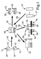
- FIG. 1 shows the structure of a control system with a center 10 and several components.
- the center 10 is also referred to as an apartment manager.
- the components are different assemblies.
- temperature controllers 11 are provided, by means of which the temperature level in a room can be monitored and which serve to setpoint the temperature level via a corresponding adjusting element 12.
- FIG. 1 shows schematically as heaters 13 electronic radiator valves, by means of which the heating power or heat radiation of so-called radiator heaters can be adjusted. However, it is possible to provide any heating devices.
- FIG. 1 shows an example of a floor heating controller 14 for adjusting the heating power of a floor heating.
- control system lighting devices 15 and shutters 16 are shown. Furthermore, heating costs distributors 17 are provided with the aid of which the heating power applied by the heating devices 13 can be monitored and evaluated.
- FIG. 1 shown control system
- the center 10 exchanges accordingly with the components 11, 13, 14, 15, 16 and 17 information or data.
- the data exchange is in FIG. 1 represented by arrows 18.
- the direction of the arrows 18 indicates the signal flow direction of the data signals between the components 11, 13, 14, 15, 16, 17 and the center 10 again. It is clear that here is a unidirectional signal transmission.
- each component 11 and the central unit 10 are assigned transmitters 19.
- the receiving devices 20 are associated with the components 13, 14, 15, 16 and the central station 10. With regard to the exact structure of the transmitting devices 19 and receiving devices 20 and with regard to a collision-free signal transmission between the components 11, 13, 14, 15, 16, 17, and the center 10 is applied to the filed for the same Applicant patent application DE-A-197 57 235 directed.
- the energy-optimized activation of the receiving devices 20 takes place according to the following in connection with FIG. 2 described inventive method. So shows FIG. 2 three activation activation profiles 21, 22 and 23.
- the activation process 21 is the activation process for the transmission devices 19.
- the activation process 22 is an activation process for the reception devices 20 during a so-called normal operation.
- the activation profile 23 is an activation profile for the receiving devices 20 during a so-called synchronization operation.
- a receiving device 20 is not activated continuously, but at predetermined intervals for a predetermined period of time.
- the temporal activation curve 22 for a receiving device 20 in normal operation can be seen that the receiving device 20, for example, every four minutes for a period of eg 300 milliseconds is activated.
- These activation times of the receiving device 20 are synchronized with a transmission cycle for data signals of a corresponding transmitting device 19.
- the data signals sent by the transmitting device 19 and to be received by the receiving device 20 are denoted by N in the activation curve 21.
- the result is that the time interval and the time duration for activating the receiving device are synchronized with the time interval and the transmission duration of the data signals of the transmitting device 19.
- the transmitting device 19 of the corresponding receiving device 20 transmits a synchronization signal, which in the temporal activation curve 21 of the FIG. 2 is denoted by S.
- the synchronization signal S contains information about the time interval of the data signals N. transmitted by the transmitting device 19.
- different transmission devices and receiving devices are present in the control system, they generally transmit and receive at different time intervals.
- the time intervals are preferably dependent on a unique device number.
- the logical assignment of the transmitting devices 19 communicating with each other as well as receiving devices 20 takes place via addresses which are contained in the synchronization signal S and the data signal N.
- the receiving device 20 will, according to the time activation curve 23 of FIG. 2 operated. Thus, in this case, a receiving device 20 remains activated until the receiving device 20 has received a corresponding synchronization signal S.
- the synchronization signal S is transmitted according to the invention during the time interval of the transmitted data signals N, namely at half the time interval. This can be the time activation curve 21 for the transmitting device 19 of the FIG. 2 be removed. Thus it is shown that data signals N are transmitted every four minutes. A synchronization signal is transmitted exactly halfway through these four minutes.
- the receiving devices / transmitting devices can therefore be operated in an energy-optimized manner. If, as described above by way of example, a receiving device is activated for only 300 msec every four minutes, this results in an energy consumption of 1/800 of the energy consumption which would be necessary if the receiving device were permanently activated.
Landscapes
- Engineering & Computer Science (AREA)
- Computer Networks & Wireless Communication (AREA)
- Physics & Mathematics (AREA)
- General Physics & Mathematics (AREA)
- Selective Calling Equipment (AREA)
Description
- Die Erfindung betrifft ein Verfahren zum Betreiben von Sende- und Empfangseinrichtungen in einem Leitsystem für einen oder mehrere Räume eines Gebäudes.
- Die Steuerung bzw. Regelung der Temperatur eines oder mehrerer Räume eines Gebäudes erfolgt üblicherweise mit Hilfe von Leitsystemen. Die Leitsysteme verfügen über mindestens eine Zentrale und über mindestens zwei mit der Zentrale in Verbindung stehende Komponenten. Bei den Komponenten handelt es sich u.a. um Temperaturregler, Heizeinrichtungen, Beleuchtungseinrichtungen und dergleichen. Zum Datenaustausch zwischen der Zentrale und den Komponenten verfügen dieselben über Sendeeinrichtungen und/oder Empfangseinrichtungen.
- Damit ein sicherer Datenaustausch zwischen den Sendeeinrichtungen und den Empfangseinrichtungen gewährleistet ist, müßte eine Empfangseinrichtungen prinzipiell dauernd eingeschaltet sein, was jedoch einen hohen Energieverbrauch zur Folge hätte. Bei batteriegespeisten Empfangseinrichtungen ist dies besonders nachteilhaft, da in diesem Fall die zur Speisung der Empfangseinrichtung eingesetzte Batterie innerhalb kurzer Zeit entladen wäre.
-
GB-A-2 271 691 - Hiervon ausgehend liegt der vorliegenden Erfindung das Problem zugrunde, ein energiesparendes und effizientes Verfahren zum Betreiben von Sende- und Empfangseinrichtungen in einem Leitsystem für einen oder mehrere Räume eines Gebäudes zu schaffen.
- Zur Lösung dieses Problems ist das eingangs genannte Verfahren durch die Merkamle des Anspruchs 1 gekennzeichnet.
- Bevorzugte Weiterbildungen der Erfindung ergeben sich aus den Unteransprüche und der Beschreibung. Nachfolgend wird ein Ausführungsbeispiel der Erfindung anhand der Zeichnungen näher erläutert. In der Zeichnung zeigt:
- Figur 1
- ein Blockschaltbild eines Leitsystems, und
- Figur 2
- schematisierte Aktivierungszustände einer erfindungsgemäß betriebenen Sendeeinrichtung und Empfangseinrichtung.
- Mit dem in der
Figur 1 dargestellten Leitsystem wird ein Temperaturniveau in einem oder mehreren Räumen eines Gebäudes individuell geregelt bzw. gesteuert. Darüber hinaus wird mit einem derartigen Leitsystem auch eine Steuerung der Beleuchtung sowie eine Steuerung der Rolläden durchgeführt. -
Figur 1 zeigt den Aufbau eines Leitsystems mit einer Zentrale 10 und mehreren Komponenten. Die Zentrale 10 wird auch als Apartment Manager bezeichnet. Bei den Komponenten handelt es sich um unterschiedliche Baugruppen. So sind Temperaturregler 11 vorgesehen, mit Hilfe derer das Temperaturniveau in einem Raum überwachbar ist und die der Sollwert-Einstellung des Temperaturniveaus über ein entsprechendes Einstellelement 12 dienen. - Des weiteren sind als Komponenten Heizeinrichtungen 13 vorgesehen.
Figur 1 zeigt schematisiert als Heizeinrichtungen 13 elektronische Heizkörperventile, mit Hilfe derer die Heizleistung bzw. Wärmeabstrahlung sogenannter Radiatorenheizkörper eingestellt werden kann. Es ist jedoch möglich, beliebige Heizeinrichtungen vorzusehen.Figur 1 zeigt exemplarisch einen Fußbodenheizungs-Regler 14 zur Einstellung der Heizleistung einer Fußbodenheizung. - Als weitere Komponenten des Leitsystems sind Beleuchtungseinrichtungen 15 sowie Rolläden 16 gezeigt. Des weiteren sind Heizkosten-Verteiler 17 vorgesehen, mit Hilfe derer die von den Heizeinrichtungen 13 aufgebrachte Heizleistung überwacht und ausgewertet werden kann.
- Bei dem in
Figur 1 gezeigten Leitsystem stehen die Komponenten 11, 13, 14, 15, 16 und 17 mit der Zentrale 10 über Funk in Verbindung. Die Zentrale 10 tauscht demnach mit den Komponenten 11, 13, 14, 15, 16 und 17 Informationen bzw. Daten aus. Der Datenaustausch ist inFigur 1 durch Pfeile 18 dargestellt. Die Richtung der Pfeile 18 gibt die Signalflußrichtung der Datensignale zwischen den Komponenten 11, 13, 14, 15, 16, 17 sowie der Zentrale 10 wieder. Daraus wird deutlich, daß hier eine unidirektionale Signalübertragung vorliegt. - Zum Senden der Signale sind jeder Komponente 11 sowie der Zentrale 10 Sendeeinrichtungen 19 zugeordnet. Zum Empfangen von Signalen sind den Komponenten 13, 14, 15, 16 sowie der Zentrale 10 Empfangseinrichtungen 20 zugeordnet. Im Hinblick auf den genauen Aufbau der Sendeeinrichtungen 19 sowie Empfangseinrichtungen 20 sowie im Hinblick auf eine kollisionsfreie Signalübertragung zwischen den Komponenten 11, 13, 14, 15, 16, 17, und der Zentrale 10 wird auf die für die gleiche Anmelderin eingereichte Patentanmeldung
DE-A-197 57 235 verwiesen. - Die energieoptimierte Aktivierung der Empfangseinrichtungen 20 erfolgt nach dem im folgenden in Verbindung mit
Figur 2 beschriebenen erfindungsgemäßen Verfahren. So zeigtFigur 2 drei schematisierte Aktivierungsverläufe 21, 22 und 23. Bei dem Aktivierungsverlauf 21 handelt es sich um den Aktivierungsverlauf für die Sendeeinrichtungen 19. Beim Aktivierungsverlauf 22 handelt es sich um ein Aktivierungsverlauf für die Empfangseinrichtungen 20 während eines sogenannten Normalbetriebs. Beim Aktivierungsverlauf 23 hingegen handelt es sich um einen Aktivierungsverlauf für die Empfangseinrichtungen 20 während eines sogenannten Synchronisationsbetriebs. - Wie
Figur 2 entnommen werden kann, wird eine Empfangseinrichtung 20 nicht durchgehend aktiviert, sondern in vorbestimmten Zeitabständen für eine vorbestimmte Zeitdauer. So kann dem zeitlichen Aktivierungsverlauf 22 für eine Empfangseinrichtung 20 im Normalbetrieb entnommen werden, daß die Empfangseinrichtung 20 z.B. alle vier Minuten für eine Zeitdauer von z.B. 300 Millisekunden aktiviert wird. Diese Aktivierungszeiten der Empfangseinrichtung 20 sind mit einem Sendezyklus für Datensignale einer entsprechenden Sendeeinrichtung 19 synchronisiert. Die von der Sendeeinrichtung 19 gesendeten und von der Empfangseinrichtung 20 zu empfangenden Datensignale sind im Aktivierungsverlauf 21 mit N bezeichnet. Beim Vergleich der Aktivierungsverläufe 21 und 22 ergibt sich umnittelbar, daß der Zeitabstand und die Zeitdauer zur Aktivierung der Empfangseinrichtung mit dem Zeitabstand und der Sendedauer der Datensignale der Sendeeinrichtung 19 synchronisiert ist. - Zur Synchronisation überträgt die Sendeeinrichtung 19 der entsprechenden Empfangseinrichtung 20 ein Synchronisationssignal, welches im zeitlichen Aktivierungsverlauf 21 der
Figur 2 mit S bezeichnet ist. Das Synchronisationssignal S enthält hierzu Informationen über den Zeitabstand der von der Sendeeinrichtung 19 übermittelten Datensignale N. - Sind im Leitsystem unterschiedliche Sendeeinrichtungen und Empfangseinrichtungen vorhanden, so senden und empfangen diesselben in der Regel mit unterschiedlichen Zeitabständen. Die Zeitabstände sind vorzugsweise abhängig von einer eindeutigen Gerätenummer. Die logische Zuordnung der miteinander kommunizierenden Sendeeinrichtungen 19 sowie Empfangseinrichtungen 20 erfolgt hierbei über Adressen, die im Synchronisationssignal S und Datensignal N enthalten sind.
- Ist z.B. infolge eines Fehlers die Synchronisation zwischen Sendeeinrichtung 19 und Empfangseinrichtung 20 verloren gegangen, oder muß eine Synchronisation bei der Inbetriebnahme des Leitsystems erfolgen, so wird die Empfangseinrichtung 20 gemäß dem zeitlichen Aktivierungsverlauf 23 der
Figur 2 betrieben. So bleibt in diesem Fall eine Empfangseinrichtung 20 solange aktiviert, bis die Empfangseinrichtung 20 ein entsprechendes Synchronisationssignal S empfangen hat. Um zur Synchronisation eine möglichst kurze Zeitdauer zu gewährleisten, wird das Synchronisationssignal S erfindungsgemäß während des Zeitabstands der gesendeten Datensignale N übermittelt, nämlich zur halben Zeit des Zeitabstands. Dies kann dem zeitlichen Aktivierungsverlauf 21 für die Sendeeinrichtung 19 derFigur 2 entnommen werden. So ist dort gezeigt, daß Datensignale N alle vier Minuten übertragen werden. Ein Synchronisationssignal wird genau zur Hälfte dieser vier Minuten übermittelt. - Mit Hilfe des erfindungsgemäßen Verfahrens können demnach die Empfangseinrichtungen/Sendeeinrichtungen energieoptimiert betrieben werden. Wird - wie oben beispielhaft beschrieben - eine Empfangseinrichtung lediglich alle vier Minuten für 300 msec aktiviert, so ergibt sich ein Energieverbrauch von 1/800 des Energieverbrauchs, der nötig wäre, wenn die Empfangseinrichtung andauernd aktiviert wäre.
-
- 10
- Zentrale
- 11
- Temperaturregler
- 12
- Einstellelement
- 13
- Heizeinrichtung
- 14
- Fußbodenheizungs-Regler
- 15
- Beleuchtungseinrichtung
- 16
- Rolladen
- 17
- Heizkosten-Verteiler
- 18
- Pfeil
- 19
- Sendeeinrichtung
- 20
- Empfangseinrichtung
- 21
- Aktivierungsverlauf
- 22
- Aktivierungsverlauf
- 23
- Aktivierungsverlauf
Claims (3)
- Verfahren zum Betreiben von Sende- und Empfangseinrichtungen in einem Leitsystem für einen oder mehrere Räume eines Gebäudes, mit den folgenden Maßnahmen:a) die oder jede Sendeeinrichtung (20) sendet von der oder jeder Empfangseinrichtung (19) zu empfangende Datensignale (N) in einem vorbestimmten Sendezyklus, nämlich mit einem vorbestimmten Zeitabstand und mit einer vorbestimmten Sendedauer,b) die oder jede Empfangseinrichtung (19) wird in einem vorbestimmten Zeitabstand und mit einer vorbestimmten Zeitdauer aktiviert, wobei der Zeitabstand und die Zeitdauer der oder jeder Empfangseinrichtung (19) mit dem Sendezyklus der oder jeder Sendeeinrichtung (20) synchronisiert sind,c) die oder jede Sendeeinrichtung (20) übermittelt an die oder jede entsprechende Empfangseinrichtung (19) zusätzlich zu Datensignalen (N) ein Synchronisationssignal (S), wobei das Synchronisationssignal (S) Informationen über den Zeitabstand der gesendeten Datensignale (N) enthält,d) eine Zuordnung der miteinander kommunizierenden Sendeeinrichtungen (20) und Empfangseinrichtungen (19) erfolgt über im Synchronisationssignal (S) und Datensignal (N) enthaltene Adressen.
- Verfahren nach Anspruch 1, dadurch gekennzeichnet, daß das Synchronisationssignal (S) während des Zeitabstands der gesendeten Datensignale (N) zur Zeit des halben Zeitabstands übermittelt wird.
- Verfahren nach Anspruch 1 oder 2, dadurch gekennzeichnet, daß zur Synchronisation die oder jede Empfangseinrichtung (19) so lange aktiviert wird, bis sie das entsprechende Synchronisationssignal (S) der entsprechenden Sendeeinrichtung (20) empfängt.
Applications Claiming Priority (3)
| Application Number | Priority Date | Filing Date | Title |
|---|---|---|---|
| DE19851959 | 1998-11-11 | ||
| DE19851959A DE19851959B4 (de) | 1998-11-11 | 1998-11-11 | Verfahren zum Betreiben von Sende- und Empfangseinrichtungen in einem Leitsystem für einen oder mehrere Räume eines Gebäudes |
| PCT/EP1999/008518 WO2000028776A1 (de) | 1998-11-11 | 1999-11-06 | Verfahren zum betreiben von sende- und empfangseinrichtungen in einem leitsystem für einen oder mehrere räume eines gebäudes |
Publications (2)
| Publication Number | Publication Date |
|---|---|
| EP1129599A1 EP1129599A1 (de) | 2001-09-05 |
| EP1129599B1 true EP1129599B1 (de) | 2009-02-11 |
Family
ID=7887400
Family Applications (1)
| Application Number | Title | Priority Date | Filing Date |
|---|---|---|---|
| EP99953971A Expired - Lifetime EP1129599B1 (de) | 1998-11-11 | 1999-11-06 | Verfahren zum betreiben von sende- und empfangseinrichtungen in einem leitsystem für einen oder mehrere räume eines gebäudes |
Country Status (6)
| Country | Link |
|---|---|
| EP (1) | EP1129599B1 (de) |
| AT (1) | ATE422786T1 (de) |
| AU (1) | AU1045700A (de) |
| CA (1) | CA2337118A1 (de) |
| DE (2) | DE19851959B4 (de) |
| WO (1) | WO2000028776A1 (de) |
Families Citing this family (9)
| Publication number | Priority date | Publication date | Assignee | Title |
|---|---|---|---|---|
| DE10133367C2 (de) * | 2001-07-10 | 2003-10-23 | Horst Ziegler | Vebrauchszähler mit einer Funksendeeinrichtung zur Funkübertragung von Zählerstandsinformationen |
| US7356360B2 (en) * | 2002-02-05 | 2008-04-08 | Honda Giken Kogyo Kabushiki Kaisha | Radio communication system |
| EP1404043B1 (de) * | 2002-09-26 | 2007-10-24 | VKR Holding A/S | Verfahren zur Steuerung von mindestens einem Sender und / oder einem Empfänger, ein Informationsvermittlungssystem, und die Verwendung des Verfahrens und des Systems |
| US7321788B2 (en) * | 2003-09-11 | 2008-01-22 | Honeywell International, Inc. | Synchronizing RF system |
| EP1754328A4 (de) * | 2004-05-13 | 2008-06-11 | Sandlinks Systems Ltd | Schnelle impuls-funksynchronisation mit niedriger stromaufnahme |
| US7860495B2 (en) | 2004-08-09 | 2010-12-28 | Siemens Industry Inc. | Wireless building control architecture |
| US7473626B2 (en) | 2006-04-11 | 2009-01-06 | International Business Machines Corporation | Control of poly-Si depletion in CMOS via gas phase doping |
| US9105179B2 (en) | 2006-06-26 | 2015-08-11 | Somfy Sas | Communication method in a home-automation installation |
| EP1873972B1 (de) | 2006-06-26 | 2018-07-04 | Somfy Activites Sa | Kommunikationsverfahren in einer heimanlage |
Family Cites Families (2)
| Publication number | Priority date | Publication date | Assignee | Title |
|---|---|---|---|---|
| GB2266031B (en) * | 1992-04-09 | 1995-11-15 | Matsushita Electric Industrial Co Ltd | A residential facility control system having a radio control capability |
| GB2271691A (en) * | 1992-09-21 | 1994-04-20 | Oconnor P J | Synchronisation of a radio telemetry system |
-
1998
- 1998-11-11 DE DE19851959A patent/DE19851959B4/de not_active Expired - Lifetime
-
1999
- 1999-11-06 WO PCT/EP1999/008518 patent/WO2000028776A1/de not_active Ceased
- 1999-11-06 EP EP99953971A patent/EP1129599B1/de not_active Expired - Lifetime
- 1999-11-06 AT AT99953971T patent/ATE422786T1/de not_active IP Right Cessation
- 1999-11-06 DE DE59914962T patent/DE59914962D1/de not_active Expired - Lifetime
- 1999-11-06 AU AU10457/00A patent/AU1045700A/en not_active Abandoned
- 1999-11-06 CA CA002337118A patent/CA2337118A1/en not_active Abandoned
Also Published As
| Publication number | Publication date |
|---|---|
| CA2337118A1 (en) | 2000-05-18 |
| EP1129599A1 (de) | 2001-09-05 |
| DE19851959B4 (de) | 2004-09-30 |
| AU1045700A (en) | 2000-05-29 |
| DE19851959A1 (de) | 2000-05-25 |
| ATE422786T1 (de) | 2009-02-15 |
| WO2000028776A1 (de) | 2000-05-18 |
| DE59914962D1 (de) | 2009-03-26 |
Similar Documents
| Publication | Publication Date | Title |
|---|---|---|
| DE69206825T2 (de) | Verfahren und vorrichtung zur überwachung des zustandes in einem raum | |
| EP0766881B1 (de) | Steuersystem für mehrere verteilt anzuordnende verbraucher, sowie verfahren zum in-betrieb-setzen eines solchen steuersystems | |
| EP0433527B1 (de) | Steuersystem für mehrere Verbraucher | |
| DE60314102T2 (de) | Initialisierung eines drahtlos gesteuerten beleuchtungssystems | |
| WO1991010276A1 (de) | Steuersystem für mehrere verbraucher | |
| DE60223144T2 (de) | Verfahren zur Steuerung von mindestens einem Sender und / oder einem Empfänger, ein Informationsvermittlungssystem, und die Verwendung des Verfahrens und des Systems | |
| EP1309760A1 (de) | System zur steuerung und überwachung von sanitärarmaturen | |
| DE19851959B4 (de) | Verfahren zum Betreiben von Sende- und Empfangseinrichtungen in einem Leitsystem für einen oder mehrere Räume eines Gebäudes | |
| EP1717927B1 (de) | Powerline-Steuersystem | |
| DE69510864T2 (de) | Verfahren zur Steuerung von Hausgerätegruppen | |
| DE3611949C2 (de) | ||
| EP0133500B1 (de) | Zeitmultiplexverfahren für ein Fernbedienungssystem für elektrische und elektronische Geräte | |
| AT408819B (de) | Regel- und/oder steuervorrichtung für die objektleittechnik | |
| DE19819127C2 (de) | Heizungssteuerungssystem | |
| EP1460507B1 (de) | Raumtemperaturregelsystem | |
| EP4245054B1 (de) | Verfahren zur funk-kanalzuweisung in einem elektronischen anzeige-system | |
| DE10202714A1 (de) | Verfahren zum Zuordnen von Betriebsadressen in einem Steuersystem für eine Vielzahl von Aktoren | |
| DE69521776T2 (de) | Steuergerät zum Öffnen und Schliessen motorisierter Verdunklungsmittel, insbesondere Rolläden | |
| EP3639379B1 (de) | Verfahren zum betrieb eines elektronischen datenerfassungsgeräts und system | |
| EP0670534B1 (de) | Regeleinrichtung für mehrere Einzelgeräte | |
| DE102018116433B4 (de) | Veranstaltungsleuchte betreibbar als Akku-Strahler und festverkabelter Strahler | |
| EP0874343A2 (de) | System zur komfortablen, mobilen Bedienung, Überwachung und zum Datenaustausch | |
| WO2004052043A2 (de) | Verfahren zum initialisieren von funkempfängern | |
| EP3932118B1 (de) | Verfahren zum betreiben eines drahtlosen feldgerätenetzwerkes | |
| AT408923B (de) | Regel- und/oder steuervorrichtung für die objektleittechnik |
Legal Events
| Date | Code | Title | Description |
|---|---|---|---|
| PUAI | Public reference made under article 153(3) epc to a published international application that has entered the european phase |
Free format text: ORIGINAL CODE: 0009012 |
|
| 17P | Request for examination filed |
Effective date: 20001207 |
|
| AK | Designated contracting states |
Kind code of ref document: A1 Designated state(s): AT BE CH CY DE DK ES FI FR GB GR IE IT LI LU MC NL PT SE |
|
| AX | Request for extension of the european patent |
Free format text: AL;LT;LV;MK;RO;SI |
|
| RAP1 | Party data changed (applicant data changed or rights of an application transferred) |
Owner name: HONEYWELL TECHNOLOGIES SARL |
|
| GRAP | Despatch of communication of intention to grant a patent |
Free format text: ORIGINAL CODE: EPIDOSNIGR1 |
|
| GRAS | Grant fee paid |
Free format text: ORIGINAL CODE: EPIDOSNIGR3 |
|
| GRAA | (expected) grant |
Free format text: ORIGINAL CODE: 0009210 |
|
| AK | Designated contracting states |
Kind code of ref document: B1 Designated state(s): AT BE CH CY DE DK ES FI FR GB GR IE IT LI LU MC NL PT SE |
|
| REG | Reference to a national code |
Ref country code: GB Ref legal event code: FG4D Free format text: NOT ENGLISH |
|
| REG | Reference to a national code |
Ref country code: CH Ref legal event code: EP |
|
| REG | Reference to a national code |
Ref country code: IE Ref legal event code: FG4D Free format text: LANGUAGE OF EP DOCUMENT: GERMAN |
|
| REF | Corresponds to: |
Ref document number: 59914962 Country of ref document: DE Date of ref document: 20090326 Kind code of ref document: P |
|
| PG25 | Lapsed in a contracting state [announced via postgrant information from national office to epo] |
Ref country code: NL Free format text: LAPSE BECAUSE OF FAILURE TO SUBMIT A TRANSLATION OF THE DESCRIPTION OR TO PAY THE FEE WITHIN THE PRESCRIBED TIME-LIMIT Effective date: 20090211 Ref country code: FI Free format text: LAPSE BECAUSE OF FAILURE TO SUBMIT A TRANSLATION OF THE DESCRIPTION OR TO PAY THE FEE WITHIN THE PRESCRIBED TIME-LIMIT Effective date: 20090211 Ref country code: ES Free format text: LAPSE BECAUSE OF FAILURE TO SUBMIT A TRANSLATION OF THE DESCRIPTION OR TO PAY THE FEE WITHIN THE PRESCRIBED TIME-LIMIT Effective date: 20090522 |
|
| NLV1 | Nl: lapsed or annulled due to failure to fulfill the requirements of art. 29p and 29m of the patents act | ||
| PG25 | Lapsed in a contracting state [announced via postgrant information from national office to epo] |
Ref country code: SE Free format text: LAPSE BECAUSE OF FAILURE TO SUBMIT A TRANSLATION OF THE DESCRIPTION OR TO PAY THE FEE WITHIN THE PRESCRIBED TIME-LIMIT Effective date: 20090511 |
|
| REG | Reference to a national code |
Ref country code: IE Ref legal event code: FD4D |
|
| PG25 | Lapsed in a contracting state [announced via postgrant information from national office to epo] |
Ref country code: PT Free format text: LAPSE BECAUSE OF FAILURE TO SUBMIT A TRANSLATION OF THE DESCRIPTION OR TO PAY THE FEE WITHIN THE PRESCRIBED TIME-LIMIT Effective date: 20090713 Ref country code: IE Free format text: LAPSE BECAUSE OF FAILURE TO SUBMIT A TRANSLATION OF THE DESCRIPTION OR TO PAY THE FEE WITHIN THE PRESCRIBED TIME-LIMIT Effective date: 20090211 Ref country code: DK Free format text: LAPSE BECAUSE OF FAILURE TO SUBMIT A TRANSLATION OF THE DESCRIPTION OR TO PAY THE FEE WITHIN THE PRESCRIBED TIME-LIMIT Effective date: 20090211 |
|
| PLBE | No opposition filed within time limit |
Free format text: ORIGINAL CODE: 0009261 |
|
| STAA | Information on the status of an ep patent application or granted ep patent |
Free format text: STATUS: NO OPPOSITION FILED WITHIN TIME LIMIT |
|
| 26N | No opposition filed |
Effective date: 20091112 |
|
| BERE | Be: lapsed |
Owner name: HONEYWELL TECHNOLOGIES SARL Effective date: 20091130 |
|
| PG25 | Lapsed in a contracting state [announced via postgrant information from national office to epo] |
Ref country code: MC Free format text: LAPSE BECAUSE OF NON-PAYMENT OF DUE FEES Effective date: 20091130 |
|
| PG25 | Lapsed in a contracting state [announced via postgrant information from national office to epo] |
Ref country code: GR Free format text: LAPSE BECAUSE OF FAILURE TO SUBMIT A TRANSLATION OF THE DESCRIPTION OR TO PAY THE FEE WITHIN THE PRESCRIBED TIME-LIMIT Effective date: 20090512 Ref country code: BE Free format text: LAPSE BECAUSE OF NON-PAYMENT OF DUE FEES Effective date: 20091130 |
|
| PG25 | Lapsed in a contracting state [announced via postgrant information from national office to epo] |
Ref country code: AT Free format text: LAPSE BECAUSE OF NON-PAYMENT OF DUE FEES Effective date: 20091106 |
|
| PG25 | Lapsed in a contracting state [announced via postgrant information from national office to epo] |
Ref country code: IT Free format text: LAPSE BECAUSE OF FAILURE TO SUBMIT A TRANSLATION OF THE DESCRIPTION OR TO PAY THE FEE WITHIN THE PRESCRIBED TIME-LIMIT Effective date: 20090211 |
|
| PG25 | Lapsed in a contracting state [announced via postgrant information from national office to epo] |
Ref country code: LU Free format text: LAPSE BECAUSE OF NON-PAYMENT OF DUE FEES Effective date: 20091106 |
|
| PG25 | Lapsed in a contracting state [announced via postgrant information from national office to epo] |
Ref country code: CY Free format text: LAPSE BECAUSE OF FAILURE TO SUBMIT A TRANSLATION OF THE DESCRIPTION OR TO PAY THE FEE WITHIN THE PRESCRIBED TIME-LIMIT Effective date: 20090211 |
|
| REG | Reference to a national code |
Ref country code: FR Ref legal event code: PLFP Year of fee payment: 17 |
|
| REG | Reference to a national code |
Ref country code: FR Ref legal event code: PLFP Year of fee payment: 18 |
|
| REG | Reference to a national code |
Ref country code: FR Ref legal event code: PLFP Year of fee payment: 19 |
|
| PGFP | Annual fee paid to national office [announced via postgrant information from national office to epo] |
Ref country code: FR Payment date: 20171127 Year of fee payment: 19 |
|
| PGFP | Annual fee paid to national office [announced via postgrant information from national office to epo] |
Ref country code: CH Payment date: 20171124 Year of fee payment: 19 |
|
| PGFP | Annual fee paid to national office [announced via postgrant information from national office to epo] |
Ref country code: DE Payment date: 20180131 Year of fee payment: 19 |
|
| PGFP | Annual fee paid to national office [announced via postgrant information from national office to epo] |
Ref country code: GB Payment date: 20181130 Year of fee payment: 20 |
|
| REG | Reference to a national code |
Ref country code: DE Ref legal event code: R119 Ref document number: 59914962 Country of ref document: DE |
|
| REG | Reference to a national code |
Ref country code: CH Ref legal event code: PL |
|
| PG25 | Lapsed in a contracting state [announced via postgrant information from national office to epo] |
Ref country code: CH Free format text: LAPSE BECAUSE OF NON-PAYMENT OF DUE FEES Effective date: 20181130 Ref country code: LI Free format text: LAPSE BECAUSE OF NON-PAYMENT OF DUE FEES Effective date: 20181130 |
|
| PG25 | Lapsed in a contracting state [announced via postgrant information from national office to epo] |
Ref country code: FR Free format text: LAPSE BECAUSE OF NON-PAYMENT OF DUE FEES Effective date: 20181130 Ref country code: DE Free format text: LAPSE BECAUSE OF NON-PAYMENT OF DUE FEES Effective date: 20190601 |
|
| REG | Reference to a national code |
Ref country code: GB Ref legal event code: PE20 Expiry date: 20191105 |
|
| PG25 | Lapsed in a contracting state [announced via postgrant information from national office to epo] |
Ref country code: GB Free format text: LAPSE BECAUSE OF EXPIRATION OF PROTECTION Effective date: 20191105 |