EP1129264B1 - Cable with parallel wires for building works structure, anchoring for said cable, and anchoring method - Google Patents
Cable with parallel wires for building works structure, anchoring for said cable, and anchoring method Download PDFInfo
- Publication number
- EP1129264B1 EP1129264B1 EP00962608A EP00962608A EP1129264B1 EP 1129264 B1 EP1129264 B1 EP 1129264B1 EP 00962608 A EP00962608 A EP 00962608A EP 00962608 A EP00962608 A EP 00962608A EP 1129264 B1 EP1129264 B1 EP 1129264B1
- Authority
- EP
- European Patent Office
- Prior art keywords
- wires
- reinforcement
- sheath
- cable
- solid
- Prior art date
- Legal status (The legal status is an assumption and is not a legal conclusion. Google has not performed a legal analysis and makes no representation as to the accuracy of the status listed.)
- Expired - Lifetime
Links
- 238000000034 method Methods 0.000 title claims description 6
- 238000004873 anchoring Methods 0.000 title claims 3
- 230000002787 reinforcement Effects 0.000 claims abstract description 25
- 239000007787 solid Substances 0.000 claims abstract description 11
- 239000000463 material Substances 0.000 claims abstract description 4
- 239000004033 plastic Substances 0.000 claims abstract description 4
- 229920003023 plastic Polymers 0.000 claims abstract description 4
- 230000002093 peripheral effect Effects 0.000 claims description 14
- 238000010276 construction Methods 0.000 claims description 10
- 239000000470 constituent Substances 0.000 claims description 6
- 239000004519 grease Substances 0.000 claims description 4
- 239000002131 composite material Substances 0.000 claims description 3
- 239000000314 lubricant Substances 0.000 claims description 3
- 229920002457 flexible plastic Polymers 0.000 claims description 2
- 238000004804 winding Methods 0.000 claims description 2
- 239000002184 metal Substances 0.000 claims 1
- 238000004806 packaging method and process Methods 0.000 claims 1
- 239000011159 matrix material Substances 0.000 description 4
- 229910000831 Steel Inorganic materials 0.000 description 2
- 239000010959 steel Substances 0.000 description 2
- 239000000725 suspension Substances 0.000 description 2
- 241000219504 Caryophyllales Species 0.000 description 1
- 239000005062 Polybutadiene Substances 0.000 description 1
- 239000004743 Polypropylene Substances 0.000 description 1
- HCHKCACWOHOZIP-UHFFFAOYSA-N Zinc Chemical compound [Zn] HCHKCACWOHOZIP-UHFFFAOYSA-N 0.000 description 1
- 238000004026 adhesive bonding Methods 0.000 description 1
- 238000005452 bending Methods 0.000 description 1
- 230000003750 conditioning effect Effects 0.000 description 1
- 238000005260 corrosion Methods 0.000 description 1
- 230000007797 corrosion Effects 0.000 description 1
- 229920001971 elastomer Polymers 0.000 description 1
- 239000000806 elastomer Substances 0.000 description 1
- 238000001125 extrusion Methods 0.000 description 1
- 229920001903 high density polyethylene Polymers 0.000 description 1
- 239000004700 high-density polyethylene Substances 0.000 description 1
- 230000001939 inductive effect Effects 0.000 description 1
- 238000002844 melting Methods 0.000 description 1
- 230000008018 melting Effects 0.000 description 1
- 229920002857 polybutadiene Polymers 0.000 description 1
- -1 polypropylene Polymers 0.000 description 1
- 229920001155 polypropylene Polymers 0.000 description 1
- 125000006850 spacer group Chemical group 0.000 description 1
- 238000005482 strain hardening Methods 0.000 description 1
- 239000000126 substance Substances 0.000 description 1
- 239000011701 zinc Substances 0.000 description 1
- 229910052725 zinc Inorganic materials 0.000 description 1
Images

Classifications
-
- E—FIXED CONSTRUCTIONS
- E04—BUILDING
- E04C—STRUCTURAL ELEMENTS; BUILDING MATERIALS
- E04C5/00—Reinforcing elements, e.g. for concrete; Auxiliary elements therefor
- E04C5/08—Members specially adapted to be used in prestressed constructions
-
- D—TEXTILES; PAPER
- D07—ROPES; CABLES OTHER THAN ELECTRIC
- D07B—ROPES OR CABLES IN GENERAL
- D07B1/00—Constructional features of ropes or cables
- D07B1/06—Ropes or cables built-up from metal wires, e.g. of section wires around a hemp core
- D07B1/0673—Ropes or cables built-up from metal wires, e.g. of section wires around a hemp core having a rope configuration
- D07B1/068—Ropes or cables built-up from metal wires, e.g. of section wires around a hemp core having a rope configuration characterised by the strand design
-
- D—TEXTILES; PAPER
- D07—ROPES; CABLES OTHER THAN ELECTRIC
- D07B—ROPES OR CABLES IN GENERAL
- D07B1/00—Constructional features of ropes or cables
- D07B1/16—Ropes or cables with an enveloping sheathing or inlays of rubber or plastics
- D07B1/162—Ropes or cables with an enveloping sheathing or inlays of rubber or plastics characterised by a plastic or rubber enveloping sheathing
-
- D—TEXTILES; PAPER
- D07—ROPES; CABLES OTHER THAN ELECTRIC
- D07B—ROPES OR CABLES IN GENERAL
- D07B1/00—Constructional features of ropes or cables
- D07B1/16—Ropes or cables with an enveloping sheathing or inlays of rubber or plastics
- D07B1/165—Ropes or cables with an enveloping sheathing or inlays of rubber or plastics characterised by a plastic or rubber inlay
-
- D—TEXTILES; PAPER
- D07—ROPES; CABLES OTHER THAN ELECTRIC
- D07B—ROPES OR CABLES IN GENERAL
- D07B5/00—Making ropes or cables from special materials or of particular form
- D07B5/002—Making parallel wire strands
-
- E—FIXED CONSTRUCTIONS
- E01—CONSTRUCTION OF ROADS, RAILWAYS, OR BRIDGES
- E01D—CONSTRUCTION OF BRIDGES, ELEVATED ROADWAYS OR VIADUCTS; ASSEMBLY OF BRIDGES
- E01D19/00—Structural or constructional details of bridges
- E01D19/16—Suspension cables; Cable clamps for suspension cables ; Pre- or post-stressed cables
-
- D—TEXTILES; PAPER
- D07—ROPES; CABLES OTHER THAN ELECTRIC
- D07B—ROPES OR CABLES IN GENERAL
- D07B2201/00—Ropes or cables
- D07B2201/20—Rope or cable components
- D07B2201/2015—Strands
- D07B2201/2023—Strands with core
-
- D—TEXTILES; PAPER
- D07—ROPES; CABLES OTHER THAN ELECTRIC
- D07B—ROPES OR CABLES IN GENERAL
- D07B2201/00—Ropes or cables
- D07B2201/20—Rope or cable components
- D07B2201/2015—Strands
- D07B2201/2033—Parallel wires
-
- D—TEXTILES; PAPER
- D07—ROPES; CABLES OTHER THAN ELECTRIC
- D07B—ROPES OR CABLES IN GENERAL
- D07B2201/00—Ropes or cables
- D07B2201/20—Rope or cable components
- D07B2201/2015—Strands
- D07B2201/2042—Strands characterised by a coating
- D07B2201/2044—Strands characterised by a coating comprising polymers
-
- D—TEXTILES; PAPER
- D07—ROPES; CABLES OTHER THAN ELECTRIC
- D07B—ROPES OR CABLES IN GENERAL
- D07B2201/00—Ropes or cables
- D07B2201/20—Rope or cable components
- D07B2201/2015—Strands
- D07B2201/2046—Strands comprising fillers
-
- D—TEXTILES; PAPER
- D07—ROPES; CABLES OTHER THAN ELECTRIC
- D07B—ROPES OR CABLES IN GENERAL
- D07B2201/00—Ropes or cables
- D07B2201/20—Rope or cable components
- D07B2201/2047—Cores
- D07B2201/2052—Cores characterised by their structure
- D07B2201/2059—Cores characterised by their structure comprising wires
- D07B2201/206—Cores characterised by their structure comprising wires arranged parallel to the axis
-
- D—TEXTILES; PAPER
- D07—ROPES; CABLES OTHER THAN ELECTRIC
- D07B—ROPES OR CABLES IN GENERAL
- D07B2201/00—Ropes or cables
- D07B2201/20—Rope or cable components
- D07B2201/2047—Cores
- D07B2201/2052—Cores characterised by their structure
- D07B2201/2059—Cores characterised by their structure comprising wires
- D07B2201/2062—Cores characterised by their structure comprising wires comprising fillers
-
- D—TEXTILES; PAPER
- D07—ROPES; CABLES OTHER THAN ELECTRIC
- D07B—ROPES OR CABLES IN GENERAL
- D07B2201/00—Ropes or cables
- D07B2201/20—Rope or cable components
- D07B2201/2047—Cores
- D07B2201/2052—Cores characterised by their structure
- D07B2201/2065—Cores characterised by their structure comprising a coating
-
- D—TEXTILES; PAPER
- D07—ROPES; CABLES OTHER THAN ELECTRIC
- D07B—ROPES OR CABLES IN GENERAL
- D07B2201/00—Ropes or cables
- D07B2201/20—Rope or cable components
- D07B2201/2071—Spacers
- D07B2201/2073—Spacers in circumferencial direction
-
- D—TEXTILES; PAPER
- D07—ROPES; CABLES OTHER THAN ELECTRIC
- D07B—ROPES OR CABLES IN GENERAL
- D07B2201/00—Ropes or cables
- D07B2201/20—Rope or cable components
- D07B2201/2083—Jackets or coverings
- D07B2201/2084—Jackets or coverings characterised by their shape
- D07B2201/2085—Jackets or coverings characterised by their shape concerning the internal shape
-
- D—TEXTILES; PAPER
- D07—ROPES; CABLES OTHER THAN ELECTRIC
- D07B—ROPES OR CABLES IN GENERAL
- D07B2201/00—Ropes or cables
- D07B2201/20—Rope or cable components
- D07B2201/2083—Jackets or coverings
- D07B2201/2084—Jackets or coverings characterised by their shape
- D07B2201/2086—Jackets or coverings characterised by their shape concerning the external shape
-
- D—TEXTILES; PAPER
- D07—ROPES; CABLES OTHER THAN ELECTRIC
- D07B—ROPES OR CABLES IN GENERAL
- D07B2205/00—Rope or cable materials
- D07B2205/20—Organic high polymers
- D07B2205/201—Polyolefins
-
- D—TEXTILES; PAPER
- D07—ROPES; CABLES OTHER THAN ELECTRIC
- D07B—ROPES OR CABLES IN GENERAL
- D07B2205/00—Rope or cable materials
- D07B2205/20—Organic high polymers
- D07B2205/2075—Rubbers, i.e. elastomers
-
- D—TEXTILES; PAPER
- D07—ROPES; CABLES OTHER THAN ELECTRIC
- D07B—ROPES OR CABLES IN GENERAL
- D07B2501/00—Application field
- D07B2501/20—Application field related to ropes or cables
- D07B2501/2015—Construction industries
- D07B2501/2023—Concrete enforcements
-
- Y—GENERAL TAGGING OF NEW TECHNOLOGICAL DEVELOPMENTS; GENERAL TAGGING OF CROSS-SECTIONAL TECHNOLOGIES SPANNING OVER SEVERAL SECTIONS OF THE IPC; TECHNICAL SUBJECTS COVERED BY FORMER USPC CROSS-REFERENCE ART COLLECTIONS [XRACs] AND DIGESTS
- Y10—TECHNICAL SUBJECTS COVERED BY FORMER USPC
- Y10T—TECHNICAL SUBJECTS COVERED BY FORMER US CLASSIFICATION
- Y10T428/00—Stock material or miscellaneous articles
- Y10T428/29—Coated or structually defined flake, particle, cell, strand, strand portion, rod, filament, macroscopic fiber or mass thereof
- Y10T428/2913—Rod, strand, filament or fiber
- Y10T428/2929—Bicomponent, conjugate, composite or collateral fibers or filaments [i.e., coextruded sheath-core or side-by-side type]
-
- Y—GENERAL TAGGING OF NEW TECHNOLOGICAL DEVELOPMENTS; GENERAL TAGGING OF CROSS-SECTIONAL TECHNOLOGIES SPANNING OVER SEVERAL SECTIONS OF THE IPC; TECHNICAL SUBJECTS COVERED BY FORMER USPC CROSS-REFERENCE ART COLLECTIONS [XRACs] AND DIGESTS
- Y10—TECHNICAL SUBJECTS COVERED BY FORMER USPC
- Y10T—TECHNICAL SUBJECTS COVERED BY FORMER US CLASSIFICATION
- Y10T428/00—Stock material or miscellaneous articles
- Y10T428/29—Coated or structually defined flake, particle, cell, strand, strand portion, rod, filament, macroscopic fiber or mass thereof
- Y10T428/2913—Rod, strand, filament or fiber
- Y10T428/2933—Coated or with bond, impregnation or core
-
- Y—GENERAL TAGGING OF NEW TECHNOLOGICAL DEVELOPMENTS; GENERAL TAGGING OF CROSS-SECTIONAL TECHNOLOGIES SPANNING OVER SEVERAL SECTIONS OF THE IPC; TECHNICAL SUBJECTS COVERED BY FORMER USPC CROSS-REFERENCE ART COLLECTIONS [XRACs] AND DIGESTS
- Y10—TECHNICAL SUBJECTS COVERED BY FORMER USPC
- Y10T—TECHNICAL SUBJECTS COVERED BY FORMER US CLASSIFICATION
- Y10T428/00—Stock material or miscellaneous articles
- Y10T428/29—Coated or structually defined flake, particle, cell, strand, strand portion, rod, filament, macroscopic fiber or mass thereof
- Y10T428/2913—Rod, strand, filament or fiber
- Y10T428/2973—Particular cross section
Definitions
- the present invention relates to the field of reinforcements used in structures of construction work.
- the invention aims particularly, but not exclusively, among these structures, those that are intended to equip cable stayed bridges, suspended or otherwise.
- the frames usually encountered in such structures include a number of wires.
- the various constituent son are generally twisted around a central wire.
- This arrangement is used to make a strand, also called strand, from reduced diameter wires.
- the mechanical characteristics of the strand obtained are higher than those of a single-strand wire whose section is equivalent to that of said strand.
- Twisting the peripheral threads around a central thread makes the strand or strand wires integral with one another and reduces the bending inertia of the assembly. This gives a reinforcement unit from very high strength son.
- the embodiment of the twisted strand or strand requires a particular stranding operation which is expensive.
- this operation causes a differential elongation between the central wire and the peripheral wires.
- the peripheral wires are then less stressed than the central wire, inducing an apparent modulus of elasticity of the lower strand than that of each constituent wire.
- the fatigue behavior of a strand as defined above is less efficient than that of the wire that constitutes it.
- the differential elongation between the peripheral wires and the central wire indeed causes differential movements with the radial pressure and therefore a friction between the son unfavorable to fatigue.
- a further disadvantage lies in the work hardening resulting from the stranding which creates a steep steel with residual internal stresses making it less ductile and therefore susceptible to creep or relaxation depending on the type of stress.
- an operation is performed consisting in exerting a high temperature voltage close to 400 ° C. This operation generates an additional cost and can be delicate because it requires a high temperature accuracy when the son are galvanized son or galfanisés. It must not exceed the melting temperature of zinc while not reducing the temperature too much otherwise the operation will be ineffective.
- a spacer device makes it possible to fill the spaces between the threads around the central thread with a flexible product such as grease or wax. This operation creates, because of the need to untwist and twist the son again, a new hardening by deformation of the peripheral son, which reduces the ductility of the strand.
- the invention aims to overcome the aforementioned drawbacks by providing an armature whose mechanical performance is equivalent to and equal to that of each of the son that constitute it.
- an armature of the kind in question is essentially characterized in that the son are substantially parallel to each other to form a bundle and in that it comprises a plastic sheath which has a lobed inner wall which is provided with depressions and projections, the peripheral wires being housed in the recess and the projections extending into the grooves.
- the subject of the invention is also a cable for a construction structure structure comprising at least two reinforcements as defined above.
- the invention further relates to a method of conditioning an armature as defined above, by parallel winding on a drum by performing a complete twist on a lathe.
- the subject of the invention is a method for implementing a construction structure of an armature as defined above, consisting in that, in at least a portion of the armature, the wires are stripped. solid and anchored stripped son to at least one constituent part of the construction work so as to work the armature in traction.
- all the solid wires of the armature are collectively jammed in an anchor jaw.
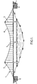
- the structure of building structure 1 shown in Figure 1 is for example a suspension bridge.
- This bridge conventionally comprises an apron 2, two pylons 3, two parallel carrying cables 4, only one being visible in the figure, and a plurality of lines 5 which are attached to the cables 4, and which carry the deck 2.
- the carrying cables 4 are stretched between two ground anchors 6 located at both ends of the bridge, and they are supported by the two pylons 3.
- Each carrier cable 4 consists of one or more armatures 10 according to a first embodiment of the invention such as that represented in FIG.
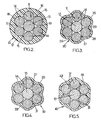
- Each armature 10 consists of a set of solid wires 11 which form a bundle wrapped in a sheath 12.
- the armature 10 thus formed is also called strand, and can be joined to other strands to form the cable 4.
- armature is meant a flexible assembly that can be rolled up to be stored and transported, and then unrolled to be installed in a construction work.
- the son 11 are generally seven in number and comprise a central wire 13 around which are disposed six peripheral son 14.
- the son 13 and 14 extend parallel to each other and are for example made of steel.
- the son 13 and 14 are mutually in contact according to their generator. Only the central wire 13 is in contact with all the other peripheral wires 14. The wires The peripherals 14 are mutually spaced apart and define grooves 15 which face towards the outside of the wire bundle 13, 14.
- All the son 13 and 14 is extruded with the sheath 12.
- This sheath forms an outer flexible plastic envelope which may be HDPE or amorphous polypropylene.
- the sheath 12 ensures the cohesion of all the son 13 and 14.
- the sheath 12 is of hollow cylindrical shape and has an outer wall 16 and an inner wall 17. The thickness of the sheath is small relative to its length.
- the outer wall 16 is, in cross section, circular while the inner wall 17 is, in cross section, lobed.
- This wall thus has recesses 18 and projections 19 which alternate alternately along the circumference of the inner wall.
- peripheral cables 14 are housed in the recesses 18 and the projections 19 extend between the cables 14 in the grooves 15. Thus, the peripheral cables are firmly held by the sheath.
- the armature 20 is distinguished from the armature 10 only by the shape of the outer wall of the sheath or sheath 22.
- This sheath has an outer wall 26 and an inner wall 27 which are in cross-section, both of lobed form.
- the inner wall 27 is similar to the inner wall 17 of the sheath 12 of the first embodiment and is provided with recesses 28 and projections 29.
- the outer wall 26 has recesses and projections respectively in correspondence of the projections and recesses of the inner wall 27.
- the armature 30 of the third embodiment shown in FIG. 4 differs from the previously described armature 20 only in that the wires 13 and 14 are embedded in an elastomeric matrix 31 such as polybutadiene or the like. This matrix occupies the interstices between the wires 13, 14.
- the elastomer 31 adheres to the yarns, by surface adhesion, preferably by chemical bonding with the sheath 22 to increase this adhesion.
- the matrix may be a lubricant such as wax or grease to reduce friction between the wires and the sheath.
- the armature 40 differs from the armature 30 described with reference to FIG. 4 by the external shape of the sheath 42.
- the outer wall 46 of this sheath is no longer lobed shape in cross section, but of polygonal shape. This shape facilitates the juxtaposition of the reinforcements or strands in order to constitute a cable 50 such as that shown in FIG. 6.
- the spaces between the strands 40 may be occupied by a matrix similar to that described above.
- the strand thus obtained according to one of the embodiments has a mechanical strength, a modulus of elasticity, fatigue performance and ductility of equivalent values and even equal to those of each wire constituting it.
- the strand In order to be packaged and transported into the area of the construction work, the strand is wound on a drum by performing a complete twist on a lathe.
- the pitch is of the order of one to three meters so that residual stresses in the elastic domain are stored in each constituent wire.
- the reinforcement obtained according to one of the embodiments is implemented within the structure 1 to have the function of one of the cables 4 or lines 5.
- a portion the armature for example the end, is stripped by removing the sheath.
- the son thus stripped are fixed by means of jaws, for example in the ground anchors 6, and the rest of the armature extends towards the pillars 3 so as to work the armature in traction.
- the set of son 13,14 are for example collectively stuck in the anchor jaw.
Landscapes
- Engineering & Computer Science (AREA)
- Architecture (AREA)
- Civil Engineering (AREA)
- Structural Engineering (AREA)
- Bridges Or Land Bridges (AREA)
- Ropes Or Cables (AREA)
- Piles And Underground Anchors (AREA)
- Installation Of Indoor Wiring (AREA)
- Reinforcement Elements For Buildings (AREA)
- Laying Of Electric Cables Or Lines Outside (AREA)
- Details Of Indoor Wiring (AREA)
- Electric Cable Installation (AREA)
Abstract
Description
La présente invention concerne le domaine des armatures utilisées dans des structures d'ouvrage de construction.The present invention relates to the field of reinforcements used in structures of construction work.
L'invention vise notamment, mais non exclusivement, parmi ces structures, celles qui sont destinées à équiper les ponts haubanés, suspendus ou autre. Les armatures habituellement rencontrées dans de telles structures comprennent un certain nombre de fils.The invention aims particularly, but not exclusively, among these structures, those that are intended to equip cable stayed bridges, suspended or otherwise. The frames usually encountered in such structures include a number of wires.
Dans les modes de réalisation connus des armatures du genre en question, voir par exemple EP-A-0855471, les différents fils constitutifs sont généralement torsadés autour d'un fil central. Cette disposition est utilisée pour réaliser un brin, également appelé toron, à partir de fils de diamètres réduits. Les caractéristiques mécaniques du brin obtenu sont plus élevées que celles d'un brin à fil unique dont la section serait équivalente à celle dudit brin.In the known embodiments of the armatures of the kind in question, see for example EP-A-0855471, the various constituent son are generally twisted around a central wire. This arrangement is used to make a strand, also called strand, from reduced diameter wires. The mechanical characteristics of the strand obtained are higher than those of a single-strand wire whose section is equivalent to that of said strand.
Torsader les fils périphériques autour d'un fil central rend solidaires entre eux les fils du brin ou toron et réduit l'inertie de flexion de l'ensemble. On obtient ainsi une unité d'armature à partir de fils de très haute résistance.Twisting the peripheral threads around a central thread makes the strand or strand wires integral with one another and reduces the bending inertia of the assembly. This gives a reinforcement unit from very high strength son.
Toutefois, la réalisation du brin torsadé ou toron nécessite une opération particulière de toronnage qui est coûteuse. De plus, cette opération provoque un allongement différentiel entre le fil central et les fils périphériques. Les fils périphériques sont alors moins sollicités que le fil central, induisant un module d'élasticité apparent du brin inférieur à celui de chaque fil constitutif.However, the embodiment of the twisted strand or strand requires a particular stranding operation which is expensive. In addition, this operation causes a differential elongation between the central wire and the peripheral wires. The peripheral wires are then less stressed than the central wire, inducing an apparent modulus of elasticity of the lower strand than that of each constituent wire.
En outre, le comportement en fatigue d'un brin tel que défini ci-dessus est moins performant que celui du fil qui le constitue. L'allongement différentiel entre les fils périphériques et le fil central provoque en effet des mouvements différentiels avec la pression radiale et donc un frottement entre les fils peu favorable à la fatigue.In addition, the fatigue behavior of a strand as defined above is less efficient than that of the wire that constitutes it. The differential elongation between the peripheral wires and the central wire indeed causes differential movements with the radial pressure and therefore a friction between the son unfavorable to fatigue.
Un inconvénient supplémentaire réside dans l'écrouissage résultant du toronnage qui crée un acier raide avec des tensions internes résiduelles le rendant moins ductile et donc susceptible de fluage ou de relaxation selon le type de sollicitation. Pour tenter de réduire cet inconvénient, on procède à une opération consistant à exercer une tension sous haute température voisine de 400°C. Cette opération engendre un surcoût et peut être délicate car elle exige une grande précision de température lorsque les fils sont des fils galvanisés ou galfanisés. Il ne faut en effet pas dépasser la température de fusion du zinc tout en ne diminuant pas trop la température sous peine de rendre l'opération inefficace.A further disadvantage lies in the work hardening resulting from the stranding which creates a steep steel with residual internal stresses making it less ductile and therefore susceptible to creep or relaxation depending on the type of stress. In an attempt to reduce this disadvantage, an operation is performed consisting in exerting a high temperature voltage close to 400 ° C. This operation generates an additional cost and can be delicate because it requires a high temperature accuracy when the son are galvanized son or galfanisés. It must not exceed the melting temperature of zinc while not reducing the temperature too much otherwise the operation will be ineffective.
En outre, afin d'obtenir une bonne protection contre la corrosion, il est d'usage d'extruder sur le brin un film en matière plastique. Préalablement à cette opération d'extrusion, un dispositif écarteur permet de remplir les espaces entre les fils autour du fil central avec un produit souple tel que de la graisse ou de la cire. Cette opération crée, du fait de la nécessité de détorsader et de torsader à nouveau les fils, un nouvel écrouissage par déformation des fils périphériques, ce qui réduit la ductilité du brin.In addition, in order to obtain good protection against corrosion, it is customary to extrude a film of plastic material onto the strand. Prior to this extrusion operation, a spacer device makes it possible to fill the spaces between the threads around the central thread with a flexible product such as grease or wax. This operation creates, because of the need to untwist and twist the son again, a new hardening by deformation of the peripheral son, which reduces the ductility of the strand.
L'invention a pour but de remédier aux inconvénients précités en fournissant une armature dont les performances mécaniques sont équivalentes et même égales à celles de chacun des fils qui la constituent.The invention aims to overcome the aforementioned drawbacks by providing an armature whose mechanical performance is equivalent to and equal to that of each of the son that constitute it.
A cet effet, selon l'invention, une armature du genre en question est essentiellement caractérisée en ce que les fils sont sensiblement parallèles entre eux pour former un faisceau et en ce qu'elle comprend une gaine en matière plastique qui possède une paroi intérieure lobée qui est munie de creux et de saillies, les fils périphériques étant logés dans le creux et les saillies s'étendant dans les gorges.For this purpose, according to the invention, an armature of the kind in question is essentially characterized in that the son are substantially parallel to each other to form a bundle and in that it comprises a plastic sheath which has a lobed inner wall which is provided with depressions and projections, the peripheral wires being housed in the recess and the projections extending into the grooves.
Grâce à cette disposition, la cohésion de l'armature obtenue est préservée tandis que les caractéristiques mécaniques de l'armature sont équivalentes ou égales à celles d'un fil constitutif.With this arrangement, the cohesion of the armature obtained is preserved while the mechanical characteristics of the armature are equivalent to or equal to those of a constituent wire.
Dans des modes de réalisation préférés de l'armature selon l'invention, on a recours en outre à l'une et/ou à l'autre des dispositions suivantes :
- les fils pleins sont des fils métalliques ;
- les fils pleins sont des fils en matériau composite ;
- la gaine possède une paroi extérieure de forme circulaire en section transversale ;
- la gaine possède une paroi extérieure de forme lobée en section transversale ;
- la gaine possède une paroi extérieure de forme sensiblement polygonale en section transversale ;
- la gaine et les fils délimitent des interstices qui sont remplis d'un lubrifiant choisi parmi la cire et la graisse ; et
- la gaine et les fils délimitent des interstices qui sont remplis par un dispositif de collage.
- the solid wires are metallic wires;
- the solid wires are wires made of composite material;
- the sheath has an outer wall of circular shape in cross section;
- the sheath has an outer wall of lobed form in cross section;
- the sheath has an outer wall of substantially polygonal shape in cross section;
- the sheath and the wires delimit interstices which are filled with a lubricant chosen from wax and grease; and
- the sheath and the wires delimit interstices which are filled by a gluing device.
Par ailleurs, l'invention a également pour objet un câble pour structure d'ouvrage de construction comprenant au moins deux armatures telles que définies ci-dessus.In addition, the subject of the invention is also a cable for a construction structure structure comprising at least two reinforcements as defined above.
L'invention a en outre pour objet un procédé de conditionnement d'une armature tel que définie ci-dessus, par enroulement parallèle sur un touret en effectuant une torsion complète sur un tour.The invention further relates to a method of conditioning an armature as defined above, by parallel winding on a drum by performing a complete twist on a lathe.
Enfin, l'invention a pour objet un procédé de mise en oeuvre dans un ouvrage de construction, d'une armature telle que définie ci-dessus, consistant en ce que, dans au moins une portion de l'armature, on dénude les fils pleins et on ancre les fils dénudés à au moins une partie constitutive de l'ouvrage de construction de façon à faire travailler l'armature en traction.Finally, the subject of the invention is a method for implementing a construction structure of an armature as defined above, consisting in that, in at least a portion of the armature, the wires are stripped. solid and anchored stripped son to at least one constituent part of the construction work so as to work the armature in traction.
De manière avantageuse, l'ensemble des fils pleins de l'armature sont coincés collectivement dans un mors d'ancrage.Advantageously, all the solid wires of the armature are collectively jammed in an anchor jaw.
D'autres caractéristiques et avantages de l'invention apparaîtront au cours de la description détaillée suivante de plusieurs de ses formes de réalisation, données à titre d'exemples non limitatifs, en regard des dessins annexés sur lesquels :
- la figure 1 est une vue schématique générale d'un pont suspendu comprenant des armatures selon la présente invention ; et
- les figures 2 à 6 sont respectivement des vues en coupe transversale d'une armature selon une première, deuxième, troisième, quatrième et cinquième formes de réalisation.
- Figure 1 is a general schematic view of a suspension bridge comprising reinforcements according to the present invention; and
- Figures 2 to 6 are respectively cross-sectional views of a frame according to a first, second, third, fourth and fifth embodiment.
La structure d'ouvrage de construction 1 représentée à la figure 1 est par exemple un pont suspendu. Ce pont comporte classiquement un tablier 2, deux pylônes 3, deux câbles porteurs parallèles 4, un seul étant visible sur la figure, et une pluralité de suspentes 5 qui sont accrochées aux câbles 4, et qui portent le tablier 2.The structure of building structure 1 shown in Figure 1 is for example a suspension bridge. This bridge conventionally comprises an apron 2, two
Les câbles porteurs 4 sont tendus entre deux ancrages au sol 6 situés aux deux extrémités du pont, et ils sont soutenus par les deux pylônes 3.The carrying cables 4 are stretched between two
Chaque câble porteur 4 est constitué d'une ou plusieurs armatures 10 selon un premier mode de réalisation de l'invention tel que celui représenté à la figure 2.Each carrier cable 4 consists of one or
Chaque armature 10 est constituée d'un ensemble de fils pleins 11 qui forment un faisceau enveloppé dans une gaine 12. L'armature 10 ainsi formée est aussi appelée brin, et peut être réunie à d'autres brins pour former le câble 4. On comprend ainsi que, par armature, on désigne un ensemble flexible qui peut être enroulé pour être stocké et transporté, puis est déroulé pour être installé dans un ouvrage de construction.Each
Dans un brin, les fils 11 sont généralement au nombre de sept et comprennent un fil central 13 autour duquel sont disposés six fils périphériques 14. Les fils 13 et 14 s'étendent parallèlement entre eux et sont par exemple réalisés en acier.In one strand, the
Les fils 13 et 14 sont mutuellement en contact selon leur génératrice. Seul le fil central 13 est en contact avec tous les autres fils périphériques 14. Les fils périphériques 14 sont mutuellement écartés deux à deux et délimitent des gorges 15 qui sont tournées vers l'extérieur du faisceau de fils 13,14.The
L'ensemble des fils 13 et 14 est extrudé avec la gaine 12. Cette gaine forme une enveloppe extérieure en matière plastique flexible qui peut être du PEHD ou du polypropylène amorphe. La gaine 12 assure la cohésion de l'ensemble des fils 13 et 14.All the
La gaine 12 est de forme cylindrique creuse et possède une paroi extérieure 16 et une paroi intérieure 17. L'épaisseur de la gaine est faible par rapport à sa longueur.The
Dans le premier mode de réalisation (figure 2), la paroi extérieure 16 est, en section transversale, de forme circulaire tandis que la paroi intérieure 17 est, en section transversale, lobée. Cette paroi possède ainsi des creux 18 et des saillies 19 qui se succèdent alternativement le long de la circonférence de la paroi intérieure.In the first embodiment (Figure 2), the
Les câbles périphériques 14 sont logés dans les creux 18 et les saillies 19 s'étendent entre les câbles 14 dans les gorges 15. Ainsi, les câbles périphériques sont fermement maintenus par la gaine.The
Dans un deuxième mode de réalisation, tel que celui représenté à la figure 3, l'armature 20 se distingue de l'armature 10 uniquement par la forme de la paroi extérieure de la gaine ou gaine 22. Cette gaine possède une paroi extérieure 26 et une paroi intérieure 27 qui sont, en coupe transversale, toutes les deux de forme lobée.In a second embodiment, such as that represented in FIG. 3, the
La paroi intérieure 27 est semblable à la paroi intérieure 17 de la gaine 12 du premier mode réalisation et est munie de creux 28 et de saillies 29. La paroi extérieure 26 possède des creux et des saillies respectivement en correspondance des saillies et des creux de la paroi intérieure 27.The
L'armature 30 du troisième mode de réalisation représenté à la figure 4, diffère de l'armature 20 précédemment décrite uniquement par le fait que les fils 13 et 14 sont noyés dans une matrice en élastomère 31 tel que du polybutadiène ou similaire. Cette matrice occupe les interstices situés entre les fils 13,14. L'élastomère 31 adhère sur les fils, par adhérence de surface, de préférence, par liaison chimique avec la gaine 22 pour augmenter cette adhérence. En variante, la matrice peut être un lubrifiant tel que de la cire ou de la graisse afin de réduire le frottement entre les fils et la gaine.The
Dans la quatrième forme de réalisation représentée à la figure 5, l'armature 40 diffère de l'armature 30 décrite en regard de la figure 4 par la forme extérieure de la gaine 42. La paroi extérieure 46 de cette gaine n'est plus de forme lobée en section transversale, mais de forme polygonale. Cette forme facilite la juxtaposition des armatures ou brins afin de constituer un câble 50 tel que celui représenté à figure 6. Les espaces entre les brins 40 peuvent être occupés par un matrice semblable à celle décrite ci-dessus.In the fourth embodiment shown in FIG. 5, the
En variante, il est possible de juxtaposer des armatures 40 dont les fils sont de diamètres différents d'une armature à l'autre.Alternatively, it is possible to juxtapose
Le brin ainsi obtenu selon l'un des modes de réalisation possède une résistance mécanique, un module d'élasticité, des performances en fatigue et une ductilité de valeurs équivalentes et mêmes égales à celles de chaque fil qui le constitue.The strand thus obtained according to one of the embodiments has a mechanical strength, a modulus of elasticity, fatigue performance and ductility of equivalent values and even equal to those of each wire constituting it.
Afin d'être conditionné et transporté jusque dans la zone de l'ouvrage de construction, le brin est enroulé sur un touret en effectuant une torsion complète sur un tour. Le pas est de l'ordre de un à trois mètres de sorte que des contraintes résiduelles dans le domaine élastique sont emmagasinées dans chaque fil constitutif.In order to be packaged and transported into the area of the construction work, the strand is wound on a drum by performing a complete twist on a lathe. The pitch is of the order of one to three meters so that residual stresses in the elastic domain are stored in each constituent wire.
Par ailleurs, l'armature obtenue selon l'un des modes de réalisation est mise en oeuvre au sein de l'ouvrage de construction 1 pour avoir la fonction de l'un des câbles 4 ou des suspentes 5. A cet effet, une portion de l'armature, par exemple l'extrémité, est dénudée en retirant la gaine. Les fils ainsi dénudés sont fixés au moyen de mors, par exemple dans les ancrages au sol 6, et le reste de l'armature s'étend en direction des piliers 3 de manière à faire travailler l'armature en traction.Furthermore, the reinforcement obtained according to one of the embodiments is implemented within the structure 1 to have the function of one of the cables 4 or lines 5. For this purpose, a portion the armature, for example the end, is stripped by removing the sheath. The son thus stripped are fixed by means of jaws, for example in the ground anchors 6, and the rest of the armature extends towards the
L'ensemble des fils 13,14 sont par exemple collectivement coincés dans le mors d'ancrage.The set of
Claims (12)
- Reinforcement (10; 20; 30; 40) for a structure of a permanent construction (1), comprising an assembly of solid wires (13, 14) forming a bundle comprising a central wire (13) and peripheral wires (14) surrounded by a sheath (12; 22; 42) made from plastic material, which peripheral wires (14) are tangential to the central wire (13) and mutually spaced to bound grooves (15), and the sheath (12; 22; 42) is made from flexible plastic material extruded onto the bundle, which sheath (12; 22; 42) has a cylindrical external shape, characterised in that the wires (13, 14) are substantially parallel with one another and the sheath (12; 22; 42) has a lobed internal wall (17; 27) incorporating hollows (18; 28) and projections (19; 29) so that the peripheral wires (14) are accommodated in the hollows (18; 28) and the projections (19; 29) extend through the grooves (15).
- Reinforcement (10; 20; 30; 40) as claimed in claim 1, in which the solid wires (13, 14) are metal wires.
- Reinforcement (10; 20; 30; 40) as claimed in claim 1, in which the solid wires (13, 14) are wires made from a composite material.
- Reinforcement (10; 20; 30; 40) as claimed in claim 1, in which the sheath (12) has an external wall (16) with a circular shape in cross-section.
- Reinforcement (10; 20; 30; 40) as claimed in claim 1, in which the sheath (22) has an external wall (26) with a lobed shape in cross-section.
- Reinforcement (10; 20; 30; 40) as claimed in claim 1, in which the sheath (42) has an external wall (46) with a substantially polygonal shape in cross-section.
- Reinforcement (10; 20; 30; 40) as claimed in claim 1, in which the sheath (12; 22; 42) and the wires (13, 14) bound interstices which are filled with a lubricant selected from wax and grease.
- Reinforcement (10; 20; 30; 40) as claimed in claim 1, in which the sheath (12; 22; 42) and the wires (13, 14) bound the interstices which are filled by means of a bonding device.
- Cable (4; 5; 50) for a structure of permanent construction comprising at least two reinforcements (10; 20; 30; 40) as claimed in claim 1.
- Method of packaging a reinforcement as claimed in claim 1 by a parallel winding of the reinforcement (10; 20; 30; 40) onto a drum, making a full twist in one turn.
- Method of employing a reinforcement as claimed in claim 1 in a permanent construction, characterised in that the solid wires (13, 14) are stripped in at least one portion of the reinforcement (10; 20; 30; 40) and the stripped wires are anchored to at least one constituent part (6) of the permanent construction (1) to make the reinforcement (10; 20; 30; 40) work under traction.
- Method of employment as claimed in claim 11, in which the solid wires (13, 14) of the reinforcement (10; 20; 30; 40) are collectively clamped in an anchoring jaw as a unit.
Applications Claiming Priority (3)
| Application Number | Priority Date | Filing Date | Title |
|---|---|---|---|
| FR9911515 | 1999-09-15 | ||
| FR9911515A FR2798408B1 (en) | 1999-09-15 | 1999-09-15 | PARALLEL WIRE CABLE FOR CONSTRUCTION OPENING STRUCTURE, ANCHORING SUCH CABLE, AND ANCHORING METHOD |
| PCT/FR2000/002509 WO2001020096A1 (en) | 1999-09-15 | 2000-09-12 | Cable with parallel wires for building works structure, anchoring for said cable, and anchoring method |
Publications (2)
| Publication Number | Publication Date |
|---|---|
| EP1129264A1 EP1129264A1 (en) | 2001-09-05 |
| EP1129264B1 true EP1129264B1 (en) | 2006-03-01 |
Family
ID=9549850
Family Applications (1)
| Application Number | Title | Priority Date | Filing Date |
|---|---|---|---|
| EP00962608A Expired - Lifetime EP1129264B1 (en) | 1999-09-15 | 2000-09-12 | Cable with parallel wires for building works structure, anchoring for said cable, and anchoring method |
Country Status (12)
| Country | Link |
|---|---|
| US (2) | US6560807B1 (en) |
| EP (1) | EP1129264B1 (en) |
| JP (1) | JP3910066B2 (en) |
| AT (1) | ATE318968T1 (en) |
| AU (1) | AU7427400A (en) |
| DE (1) | DE60026330T2 (en) |
| DK (1) | DK1129264T3 (en) |
| ES (1) | ES2258473T3 (en) |
| FR (1) | FR2798408B1 (en) |
| HK (1) | HK1038252A1 (en) |
| PT (1) | PT1129264E (en) |
| WO (1) | WO2001020096A1 (en) |
Families Citing this family (20)
| Publication number | Priority date | Publication date | Assignee | Title |
|---|---|---|---|---|
| JP2002339279A (en) * | 2001-05-14 | 2002-11-27 | Times Engineering:Kk | Tensile cable for building and engineering work |
| US6880193B2 (en) * | 2002-04-02 | 2005-04-19 | Figg Bridge Engineers, Inc. | Cable-stay cradle system |
| AU2003304059A1 (en) * | 2003-03-24 | 2004-11-19 | Freyssinet | Construction cable |
| DK1629154T5 (en) * | 2003-06-02 | 2008-10-27 | Freyssinet | Method for anchoring parallel wire cables |
| US7891070B2 (en) * | 2007-04-14 | 2011-02-22 | Air Logistics Corporation | Method for handling elongate strength members |
| AT504886B1 (en) * | 2007-09-10 | 2008-09-15 | Thal Hermann Dipl Ing | BANDED TENSIONING ELEMENT |
| US7803465B2 (en) * | 2008-06-17 | 2010-09-28 | Specialty Minerals (Michigan) Inc. | Strand cladding of calcium wire |
| JP2009068333A (en) * | 2008-12-15 | 2009-04-02 | Sumitomo Denko Steel Wire Kk | Handling method of prefabricated cable |
| WO2010069837A1 (en) * | 2008-12-18 | 2010-06-24 | Nv Bekaert Sa | A cord for reinforcement of a cementitious matrix |
| KR101137474B1 (en) * | 2009-12-24 | 2012-04-20 | 재단법인 포항산업과학연구원 | Magnetorheological cable and mechanism using the same |
| KR101171039B1 (en) * | 2010-09-02 | 2012-08-06 | 오베아룹코리아(주) | Partially and fully earth-anchored cable-stayed bridge using main span prestressing appratus and construction method for the same |
| US8438826B2 (en) * | 2010-10-11 | 2013-05-14 | Wireco Worldgroup Inc. | Four strand blackened wire rope |
| US8474219B2 (en) | 2011-07-13 | 2013-07-02 | Ultimate Strength Cable, LLC | Stay cable for structures |
| US20120260590A1 (en) * | 2011-04-12 | 2012-10-18 | Lambert Walter L | Parallel Wire Cable |
| WO2013131827A2 (en) * | 2012-03-09 | 2013-09-12 | Nv Bekaert Sa | Strand, cable bolt and its installation |
| JP6161397B2 (en) * | 2013-05-16 | 2017-07-12 | 大成建設株式会社 | PC cable |
| CN105421244B (en) * | 2015-12-10 | 2017-07-28 | 江苏法尔胜缆索有限公司 | A kind of preparation method of main rope of suspension bridge Prefabricated parallel preshaping of wire strand |
| FR3051484A1 (en) * | 2016-05-18 | 2017-11-24 | Michelin & Cie | REINFORCING ELEMENT FOR BANDING, REINFORCED PRODUCT COMPRISING SUCH REINFORCING ELEMENT, BANDAGE COMPRISING SUCH REINFORCING ELEMENT OR REINFORCED PRODUCT, AND METHOD FOR MANUFACTURING SUCH REINFORCING ELEMENT |
| EP3284865B1 (en) * | 2016-08-19 | 2023-01-18 | VSL International AG | Cable anchorage with seal element and prestressing system comprising such anchorage |
| JP6936059B2 (en) * | 2017-06-30 | 2021-09-15 | 株式会社ブリヂストン | Steel cord for reinforcing rubber articles |
Citations (8)
| Publication number | Priority date | Publication date | Assignee | Title |
|---|---|---|---|---|
| US3500625A (en) * | 1967-05-17 | 1970-03-17 | Isao Gokyu | Parallel cables |
| US4197695A (en) * | 1977-11-08 | 1980-04-15 | Bethlehem Steel Corporation | Method of making sealed wire rope |
| US4473915A (en) * | 1981-09-30 | 1984-10-02 | Dyckerhoff & Widmann Aktiengesellschaft | Tension member and a method of assembling and installing the tension member |
| US4693044A (en) * | 1985-10-10 | 1987-09-15 | Freyssinet International (Stup) | Devices for prestressing concrete having stretched sinuous cables and the methods for implementing same |
| DE3644414A1 (en) * | 1986-09-26 | 1988-04-07 | Wolfhart Andrae | Plastic material for filling hollow spaces within a plastic tube filled with a bundle of parallel steel wires or steel litz wires |
| US4813221A (en) * | 1983-12-20 | 1989-03-21 | Bridin Plc. | Flexible tension members |
| FR2675523A1 (en) * | 1991-04-22 | 1992-10-23 | Scetauroute | Stay cable, in particular for cable-stayed bridge, consisting of a bundle of identical strands each formed by several wires (filaments) |
| EP0896108A2 (en) * | 1997-08-05 | 1999-02-10 | Dyckerhoff & Widmann Aktiengesellschaft | Method for installing and tensioning a free tendon, and device for carrying out the method |
Family Cites Families (28)
| Publication number | Priority date | Publication date | Assignee | Title |
|---|---|---|---|---|
| US1537698A (en) * | 1924-10-15 | 1925-05-12 | Holton D Robinson | Laying of and seizing for suspension-bridge cables |
| US1678292A (en) * | 1925-01-22 | 1928-07-24 | American Steel & Wire Co | Cable |
| US1921606A (en) * | 1928-11-01 | 1933-08-08 | Cremer Carl | Multicore high tension cable |
| US2095721A (en) * | 1932-05-24 | 1937-10-12 | Roeblings John A Sons Co | Wire cable |
| GB1193354A (en) * | 1966-08-25 | 1970-05-28 | Bethlehem Steel Corp | Parallel Wire Strand, and method and apparatus for manufacture thereof |
| US3548432A (en) * | 1967-02-08 | 1970-12-22 | Bethlehem Steel Corp | Suspension bridge cable anchorage |
| US3457717A (en) * | 1968-08-02 | 1969-07-29 | Bethlehem Steel Corp | Plastic coated cable and method of making same |
| US3673624A (en) * | 1969-08-18 | 1972-07-04 | Dyckerhoff & Widmann Ag | Suspension bridge |
| US3919762A (en) * | 1972-08-05 | 1975-11-18 | Wolfgang Borelly | Process for the manufacture of parallel wire strands for bridges and the like by winding and unwinding |
| US4117582A (en) * | 1972-08-05 | 1978-10-03 | Wolfgang Borelly | Apparatus for producing parallel wire strands for bridges and the like by winding and unwinding strand of large cross-section and for simultaneously applying corrosion protection thereto |
| US4160613A (en) * | 1978-06-23 | 1979-07-10 | Tad Stanwick | Pile anchor for moorings |
| US4247225A (en) * | 1979-09-06 | 1981-01-27 | Kamak Corporation | Alignment device |
| JPS59173712U (en) * | 1983-05-09 | 1984-11-20 | 株式会社 春本鐵工所 | Bridge cable anchor socket |
| DE3437107A1 (en) * | 1984-10-10 | 1986-04-10 | Dyckerhoff & Widmann AG, 8000 München | TIE LINK, ESPECIALLY SLOPED ROPE FOR A SLIDING ROPE BRIDGE |
| DE3437108A1 (en) * | 1984-10-10 | 1986-04-10 | Dyckerhoff & Widmann AG, 8000 München | DEVICE FOR USE IN THE ASSEMBLY OF A TENSION MEMBER OF STEEL WIRE, STRAND, OR THE LIKE |
| JPS61122360A (en) * | 1984-11-20 | 1986-06-10 | 川鉄テクノワイヤ株式会社 | Unbond pc steel twisted wire |
| FR2663975B1 (en) * | 1990-06-29 | 1993-07-09 | Freyssinet Int Stup | IMPROVEMENTS ON BRIDGE BRIDGES AND MORE ESPECIALLY THEIR PYLONES AND BRIDGES. |
| US5208077A (en) * | 1990-11-09 | 1993-05-04 | Florida Wire And Cable Company | Method for a composite material comprising coated and filled metal strand for use in prestressed concrete, stay cables for cable-stayed bridges and other uses |
| WO1993008976A1 (en) * | 1991-11-01 | 1993-05-13 | Applied Research Of Australia Pty Ltd | Polymeric mouldings reinforced with tows of fibres |
| US5390386A (en) * | 1993-06-01 | 1995-02-21 | The D. S. Brown Company, Inc. | Suspension bridge cable wrap and application method |
| DE69411680T2 (en) * | 1993-12-02 | 1998-11-12 | Hien Electric Ind Ltd | Wire strand with an anti-corrosion coating and process for its manufacture |
| JP2936087B2 (en) * | 1994-04-06 | 1999-08-23 | 神鋼鋼線工業株式会社 | Bridge cables |
| DE4441772C2 (en) * | 1994-11-24 | 1999-03-25 | Vls International Ag | Prestressed tension member made of tension wires and method for erecting such a tension member |
| FR2739113B1 (en) * | 1995-09-26 | 1997-12-05 | Freyssinet Int Stup | INDIVIDUALLY PROTECTED STRAND FOR SUSPENDED CIVIL ENGINEERING STRUCTURE, STRUCTURE INCLUDING SUCH STRANDS, AND METHOD OF MANUFACTURE |
| FR2744467B1 (en) * | 1996-02-06 | 1998-04-03 | Freyssinet Int Stup | SUSPENSION DEVICE FOR CIVIL ENGINEERING STRUCTURE AND CONSTRUCTION METHOD |
| FR2780127B1 (en) * | 1998-06-19 | 2000-09-08 | Freyssinet Int Stup | METHOD AND DEVICE FOR HANGING A LOAD TRANSMITTER ELEMENT ON A CABLE, AND SUSPENDED BRIDGE COMPRISING SUCH DEVICES |
| EP1013830A1 (en) * | 1998-12-24 | 2000-06-28 | Freyssinet International Stup | Device and process for fastening a building element and a cable structure and suspension bridge having such devices |
| FR2794477B1 (en) * | 1999-06-02 | 2001-09-14 | Freyssinet Int Stup | CONSTRUCTION OPENING STRUCTURE CABLE, SHEATH SECTION OF SUCH CABLE, AND LAYING METHOD |
-
1999
- 1999-09-15 FR FR9911515A patent/FR2798408B1/en not_active Expired - Lifetime
-
2000
- 2000-09-12 EP EP00962608A patent/EP1129264B1/en not_active Expired - Lifetime
- 2000-09-12 JP JP2001523456A patent/JP3910066B2/en not_active Expired - Fee Related
- 2000-09-12 WO PCT/FR2000/002509 patent/WO2001020096A1/en active IP Right Grant
- 2000-09-12 AU AU74274/00A patent/AU7427400A/en not_active Abandoned
- 2000-09-12 AT AT00962608T patent/ATE318968T1/en not_active IP Right Cessation
- 2000-09-12 ES ES00962608T patent/ES2258473T3/en not_active Expired - Lifetime
- 2000-09-12 PT PT00962608T patent/PT1129264E/en unknown
- 2000-09-12 DE DE60026330T patent/DE60026330T2/en not_active Expired - Lifetime
- 2000-09-12 DK DK00962608T patent/DK1129264T3/en active
- 2000-09-12 US US09/831,840 patent/US6560807B1/en not_active Expired - Lifetime
-
2001
- 2001-11-20 HK HK01108155A patent/HK1038252A1/en not_active IP Right Cessation
-
2003
- 2003-01-30 US US10/354,318 patent/US6658684B2/en not_active Expired - Lifetime
Patent Citations (8)
| Publication number | Priority date | Publication date | Assignee | Title |
|---|---|---|---|---|
| US3500625A (en) * | 1967-05-17 | 1970-03-17 | Isao Gokyu | Parallel cables |
| US4197695A (en) * | 1977-11-08 | 1980-04-15 | Bethlehem Steel Corporation | Method of making sealed wire rope |
| US4473915A (en) * | 1981-09-30 | 1984-10-02 | Dyckerhoff & Widmann Aktiengesellschaft | Tension member and a method of assembling and installing the tension member |
| US4813221A (en) * | 1983-12-20 | 1989-03-21 | Bridin Plc. | Flexible tension members |
| US4693044A (en) * | 1985-10-10 | 1987-09-15 | Freyssinet International (Stup) | Devices for prestressing concrete having stretched sinuous cables and the methods for implementing same |
| DE3644414A1 (en) * | 1986-09-26 | 1988-04-07 | Wolfhart Andrae | Plastic material for filling hollow spaces within a plastic tube filled with a bundle of parallel steel wires or steel litz wires |
| FR2675523A1 (en) * | 1991-04-22 | 1992-10-23 | Scetauroute | Stay cable, in particular for cable-stayed bridge, consisting of a bundle of identical strands each formed by several wires (filaments) |
| EP0896108A2 (en) * | 1997-08-05 | 1999-02-10 | Dyckerhoff & Widmann Aktiengesellschaft | Method for installing and tensioning a free tendon, and device for carrying out the method |
Also Published As
| Publication number | Publication date |
|---|---|
| FR2798408A1 (en) | 2001-03-16 |
| WO2001020096A1 (en) | 2001-03-22 |
| DK1129264T3 (en) | 2006-07-10 |
| US20030110583A1 (en) | 2003-06-19 |
| JP2003509604A (en) | 2003-03-11 |
| US6560807B1 (en) | 2003-05-13 |
| PT1129264E (en) | 2006-07-31 |
| ES2258473T3 (en) | 2006-09-01 |
| HK1038252A1 (en) | 2002-03-08 |
| US6658684B2 (en) | 2003-12-09 |
| AU7427400A (en) | 2001-04-17 |
| ATE318968T1 (en) | 2006-03-15 |
| DE60026330D1 (en) | 2006-04-27 |
| JP3910066B2 (en) | 2007-04-25 |
| DE60026330T2 (en) | 2006-10-19 |
| EP1129264A1 (en) | 2001-09-05 |
| FR2798408B1 (en) | 2002-01-18 |
Similar Documents
| Publication | Publication Date | Title |
|---|---|---|
| EP1129264B1 (en) | Cable with parallel wires for building works structure, anchoring for said cable, and anchoring method | |
| EP1211350B1 (en) | Individually protected strand, its utilisation in construction and method for its manufacture | |
| EP0130191B1 (en) | Filiform elements usable for reinforcing mouldable materials, particularly concrete | |
| LU84984A1 (en) | CABLES AND THEIR MANUFACTURING METHOD | |
| FR2464834A1 (en) | TIRE WITH RADIAL CARCASS | |
| FR2698181A1 (en) | Optical fiber cable and its manufacturing process | |
| FR3032978A1 (en) | MULTITORON 1XN STRUCTURE CABLE FOR PNEUMATIC PROTECTION FRAME | |
| LU83518A1 (en) | METAL CABLES FOR THE REINFORCEMENT OF ELASTOMERIC MANUFACTURED PRODUCTS | |
| FR2732502A1 (en) | CABLE SUSPENDED, IN PARTICULAR FOR TRANSMISSION OF ENERGY | |
| CA1191915A (en) | Anchoring and linking sleeve for heterogeneous electric cable | |
| FR2468684A1 (en) | SYNTHETIC FIBER CABLE | |
| FR3111923A1 (en) | Two-layer multi-strand cable with improved flexural strength | |
| EP0364317A1 (en) | Optical cable | |
| EP0950762A1 (en) | Suspension device for building constructions | |
| FR2676466A1 (en) | Steel tyre cord and a tyre incorporating it | |
| FR2551104A1 (en) | METALLIC CABLE | |
| FR2505057A1 (en) | Non-metallic fibre=optic cable - has fibre cable forming core helically surrounded by optical fibres inside outer sheath | |
| WO2012017135A1 (en) | Strand, structural cable and method for manufacturing the strand | |
| EP4172407A1 (en) | Double-layer multi-strand cable having improved bending endurance | |
| FR2718564A1 (en) | Self-supporting cable, especially guard cable. | |
| BE897633A (en) | Cables and manufacturing process | |
| FR2488626A1 (en) | ONE-TORON METAL CABLE FOR ARMING ELASTOMERIC PRODUCTS | |
| JP2847054B2 (en) | Ground anchor method | |
| FR2747696A1 (en) | METHOD FOR MANUFACTURING A CORROSION ESTROPE AND ESTROPE THUS OBTAINED | |
| FR3130858A1 (en) | Two-layer multi-strand rope with improved flexural endurance |
Legal Events
| Date | Code | Title | Description |
|---|---|---|---|
| PUAI | Public reference made under article 153(3) epc to a published international application that has entered the european phase |
Free format text: ORIGINAL CODE: 0009012 |
|
| 17P | Request for examination filed |
Effective date: 20010518 |
|
| AK | Designated contracting states |
Kind code of ref document: A1 Designated state(s): AT BE CH CY DE DK ES FI FR GB GR IE IT LI LU MC NL |
|
| AX | Request for extension of the european patent |
Free format text: AL;LT;LV;MK PAYMENT 20010518;RO PAYMENT 20010518;SI |
|
| 17Q | First examination report despatched |
Effective date: 20040206 |
|
| GRAP | Despatch of communication of intention to grant a patent |
Free format text: ORIGINAL CODE: EPIDOSNIGR1 |
|
| RBV | Designated contracting states (corrected) |
Designated state(s): AT BE CH CY DE DK ES FI FR GB GR IE IT LI LU MC NL PT SE |
|
| GRAS | Grant fee paid |
Free format text: ORIGINAL CODE: EPIDOSNIGR3 |
|
| RAP1 | Party data changed (applicant data changed or rights of an application transferred) |
Owner name: FREYSSINET |
|
| GRAA | (expected) grant |
Free format text: ORIGINAL CODE: 0009210 |
|
| AK | Designated contracting states |
Kind code of ref document: B1 Designated state(s): AT BE CH CY DE DK ES FI FR GB GR IE IT LI LU MC NL PT SE |
|
| AX | Request for extension of the european patent |
Extension state: MK RO |
|
| PG25 | Lapsed in a contracting state [announced via postgrant information from national office to epo] |
Ref country code: AT Free format text: LAPSE BECAUSE OF FAILURE TO SUBMIT A TRANSLATION OF THE DESCRIPTION OR TO PAY THE FEE WITHIN THE PRESCRIBED TIME-LIMIT Effective date: 20060301 Ref country code: FI Free format text: LAPSE BECAUSE OF FAILURE TO SUBMIT A TRANSLATION OF THE DESCRIPTION OR TO PAY THE FEE WITHIN THE PRESCRIBED TIME-LIMIT Effective date: 20060301 Ref country code: NL Free format text: LAPSE BECAUSE OF FAILURE TO SUBMIT A TRANSLATION OF THE DESCRIPTION OR TO PAY THE FEE WITHIN THE PRESCRIBED TIME-LIMIT Effective date: 20060301 |
|
| REG | Reference to a national code |
Ref country code: GB Ref legal event code: FG4D Free format text: NOT ENGLISH |
|
| REG | Reference to a national code |
Ref country code: CH Ref legal event code: EP |
|
| REG | Reference to a national code |
Ref country code: IE Ref legal event code: FG4D Free format text: LANGUAGE OF EP DOCUMENT: FRENCH |
|
| REF | Corresponds to: |
Ref document number: 60026330 Country of ref document: DE Date of ref document: 20060427 Kind code of ref document: P |
|
| PG25 | Lapsed in a contracting state [announced via postgrant information from national office to epo] |
Ref country code: SE Free format text: LAPSE BECAUSE OF FAILURE TO SUBMIT A TRANSLATION OF THE DESCRIPTION OR TO PAY THE FEE WITHIN THE PRESCRIBED TIME-LIMIT Effective date: 20060601 |
|
| REG | Reference to a national code |
Ref country code: HK Ref legal event code: GR Ref document number: 1038252 Country of ref document: HK |
|
| GBT | Gb: translation of ep patent filed (gb section 77(6)(a)/1977) |
Effective date: 20060607 |
|
| REG | Reference to a national code |
Ref country code: DK Ref legal event code: T3 |
|
| REG | Reference to a national code |
Ref country code: PT Ref legal event code: SC4A Effective date: 20060531 |
|
| NLV1 | Nl: lapsed or annulled due to failure to fulfill the requirements of art. 29p and 29m of the patents act | ||
| REG | Reference to a national code |
Ref country code: ES Ref legal event code: FG2A Ref document number: 2258473 Country of ref document: ES Kind code of ref document: T3 |
|
| PG25 | Lapsed in a contracting state [announced via postgrant information from national office to epo] |
Ref country code: LI Free format text: LAPSE BECAUSE OF NON-PAYMENT OF DUE FEES Effective date: 20060930 Ref country code: MC Free format text: LAPSE BECAUSE OF NON-PAYMENT OF DUE FEES Effective date: 20060930 Ref country code: CH Free format text: LAPSE BECAUSE OF NON-PAYMENT OF DUE FEES Effective date: 20060930 |
|
| PLBE | No opposition filed within time limit |
Free format text: ORIGINAL CODE: 0009261 |
|
| STAA | Information on the status of an ep patent application or granted ep patent |
Free format text: STATUS: NO OPPOSITION FILED WITHIN TIME LIMIT |
|
| 26N | No opposition filed |
Effective date: 20061204 |
|
| REG | Reference to a national code |
Ref country code: CH Ref legal event code: PL |
|
| PG25 | Lapsed in a contracting state [announced via postgrant information from national office to epo] |
Ref country code: GR Free format text: LAPSE BECAUSE OF FAILURE TO SUBMIT A TRANSLATION OF THE DESCRIPTION OR TO PAY THE FEE WITHIN THE PRESCRIBED TIME-LIMIT Effective date: 20060602 |
|
| PG25 | Lapsed in a contracting state [announced via postgrant information from national office to epo] |
Ref country code: LU Free format text: LAPSE BECAUSE OF NON-PAYMENT OF DUE FEES Effective date: 20060912 |
|
| PG25 | Lapsed in a contracting state [announced via postgrant information from national office to epo] |
Ref country code: CY Free format text: LAPSE BECAUSE OF FAILURE TO SUBMIT A TRANSLATION OF THE DESCRIPTION OR TO PAY THE FEE WITHIN THE PRESCRIBED TIME-LIMIT Effective date: 20060301 |
|
| PGFP | Annual fee paid to national office [announced via postgrant information from national office to epo] |
Ref country code: IE Payment date: 20110826 Year of fee payment: 12 |
|
| PGFP | Annual fee paid to national office [announced via postgrant information from national office to epo] |
Ref country code: DE Payment date: 20110902 Year of fee payment: 12 |
|
| REG | Reference to a national code |
Ref country code: IE Ref legal event code: MM4A |
|
| PG25 | Lapsed in a contracting state [announced via postgrant information from national office to epo] |
Ref country code: DE Free format text: LAPSE BECAUSE OF NON-PAYMENT OF DUE FEES Effective date: 20130403 Ref country code: IE Free format text: LAPSE BECAUSE OF NON-PAYMENT OF DUE FEES Effective date: 20120912 |
|
| REG | Reference to a national code |
Ref country code: DE Ref legal event code: R119 Ref document number: 60026330 Country of ref document: DE Effective date: 20130403 |
|
| REG | Reference to a national code |
Ref country code: FR Ref legal event code: PLFP Year of fee payment: 16 |
|
| REG | Reference to a national code |
Ref country code: FR Ref legal event code: PLFP Year of fee payment: 17 |
|
| REG | Reference to a national code |
Ref country code: FR Ref legal event code: PLFP Year of fee payment: 18 |
|
| REG | Reference to a national code |
Ref country code: FR Ref legal event code: PLFP Year of fee payment: 19 |
|
| PGFP | Annual fee paid to national office [announced via postgrant information from national office to epo] |
Ref country code: FR Payment date: 20180822 Year of fee payment: 19 Ref country code: IT Payment date: 20180828 Year of fee payment: 19 |
|
| PGFP | Annual fee paid to national office [announced via postgrant information from national office to epo] |
Ref country code: DK Payment date: 20180824 Year of fee payment: 19 Ref country code: BE Payment date: 20180822 Year of fee payment: 19 Ref country code: GB Payment date: 20180823 Year of fee payment: 19 |
|
| PGFP | Annual fee paid to national office [announced via postgrant information from national office to epo] |
Ref country code: PT Payment date: 20180903 Year of fee payment: 19 |
|
| PGFP | Annual fee paid to national office [announced via postgrant information from national office to epo] |
Ref country code: ES Payment date: 20181001 Year of fee payment: 19 |
|
| REG | Reference to a national code |
Ref country code: DK Ref legal event code: EBP Effective date: 20190930 |
|
| PG25 | Lapsed in a contracting state [announced via postgrant information from national office to epo] |
Ref country code: PT Free format text: LAPSE BECAUSE OF NON-PAYMENT OF DUE FEES Effective date: 20200312 |
|
| PG25 | Lapsed in a contracting state [announced via postgrant information from national office to epo] |
Ref country code: PT Free format text: LAPSE BECAUSE OF NON-PAYMENT OF DUE FEES Effective date: 20200422 |
|
| REG | Reference to a national code |
Ref country code: BE Ref legal event code: MM Effective date: 20190930 |
|
| PG25 | Lapsed in a contracting state [announced via postgrant information from national office to epo] |
Ref country code: IT Free format text: LAPSE BECAUSE OF NON-PAYMENT OF DUE FEES Effective date: 20190912 Ref country code: BE Free format text: LAPSE BECAUSE OF NON-PAYMENT OF DUE FEES Effective date: 20190930 |
|
| GBPC | Gb: european patent ceased through non-payment of renewal fee |
Effective date: 20190912 |
|
| PG25 | Lapsed in a contracting state [announced via postgrant information from national office to epo] |
Ref country code: FR Free format text: LAPSE BECAUSE OF NON-PAYMENT OF DUE FEES Effective date: 20190930 Ref country code: DK Free format text: LAPSE BECAUSE OF NON-PAYMENT OF DUE FEES Effective date: 20190930 Ref country code: GB Free format text: LAPSE BECAUSE OF NON-PAYMENT OF DUE FEES Effective date: 20190912 Ref country code: PT Free format text: LAPSE BECAUSE OF EXPIRATION OF PROTECTION Effective date: 20200923 |
|
| REG | Reference to a national code |
Ref country code: ES Ref legal event code: FD2A Effective date: 20210127 |
|
| PG25 | Lapsed in a contracting state [announced via postgrant information from national office to epo] |
Ref country code: ES Free format text: LAPSE BECAUSE OF NON-PAYMENT OF DUE FEES Effective date: 20190913 |
|
| PG25 | Lapsed in a contracting state [announced via postgrant information from national office to epo] |
Ref country code: PT Free format text: LAPSE BECAUSE OF NON-PAYMENT OF DUE FEES Effective date: 20190912 |
|
| PG25 | Lapsed in a contracting state [announced via postgrant information from national office to epo] |
Ref country code: PT Free format text: LAPSE BECAUSE OF NON-PAYMENT OF DUE FEES Effective date: 20190912 |