EP1128523A2 - Stator pour moteur/générateur électrique avec un nombre mi-entier de spires - Google Patents
Stator pour moteur/générateur électrique avec un nombre mi-entier de spires Download PDFInfo
- Publication number
- EP1128523A2 EP1128523A2 EP01301378A EP01301378A EP1128523A2 EP 1128523 A2 EP1128523 A2 EP 1128523A2 EP 01301378 A EP01301378 A EP 01301378A EP 01301378 A EP01301378 A EP 01301378A EP 1128523 A2 EP1128523 A2 EP 1128523A2
- Authority
- EP
- European Patent Office
- Prior art keywords
- wire
- slot
- coils
- wound
- winding
- Prior art date
- Legal status (The legal status is an assumption and is not a legal conclusion. Google has not performed a legal analysis and makes no representation as to the accuracy of the status listed.)
- Granted
Links
Images

Classifications
-
- F—MECHANICAL ENGINEERING; LIGHTING; HEATING; WEAPONS; BLASTING
- F02—COMBUSTION ENGINES; HOT-GAS OR COMBUSTION-PRODUCT ENGINE PLANTS
- F02N—STARTING OF COMBUSTION ENGINES; STARTING AIDS FOR SUCH ENGINES, NOT OTHERWISE PROVIDED FOR
- F02N11/00—Starting of engines by means of electric motors
- F02N11/04—Starting of engines by means of electric motors the motors being associated with current generators
-
- H—ELECTRICITY
- H02—GENERATION; CONVERSION OR DISTRIBUTION OF ELECTRIC POWER
- H02K—DYNAMO-ELECTRIC MACHINES
- H02K3/00—Details of windings
- H02K3/04—Windings characterised by the conductor shape, form or construction, e.g. with bar conductors
- H02K3/28—Layout of windings or of connections between windings
Definitions
- the present invention relates to a stator for a polyphase electric motor/generator and, particularly, to a stator for a three-phase motor/generator having three phase windings with each phase winding including two groups of coils electrically connected in parallel.
- Three-phase induction motors are important and popular motors used for a variety of applications. Three-phase motors are popular because the horsepower rating of a three-phase induction motor is typically 167 percent more than a single-phase induction motor having the same weight.
- An exemplary use for a three-phase motor is using the motor as a starter motor for an internal combustion engine.
- the starter motor assists the internal combustion engine during engine starting until the engine can sufficiently operate without the assistance of the starter motor.
- the internal combustion engine can be an engine for a lawn mower, tractor, automobile, power-generation system, or the like.
- the invention provides a polyphase electric motor/generator and a controller.
- the polyphase motor is typically a three-phase motor/generator having a rotor and a stator.
- the rotor is interconnected with a drive shaft of the engine such that when the rotor rotates the drive shaft also rotates.
- the stator includes a core having slots for receiving electrical wire.
- the stator further includes three phase windings.
- the three phase windings include wire that is wound in the slots of the core and are electrically connected to the controller.
- the controller provides a substantially alternating current (AC) three-phase signal to the phase windings resulting in a magnetic field being induced within the core.
- AC substantially alternating current
- the amount of torque a three-phase electric motor generates is dependent upon the amount of electric current flowing in the phase windings.
- the flow of electric current in the phase windings induces the magnetic field within the stator core for interaction with the rotor magnetic field, resulting in the rotation of the rotor. Assuming everything else is equal, the larger the current in the phase windings, the stronger the magnetic field within the stator core and, consequently, the greater the amount of torque that is generated by the rotor.
- One way to increase current flow in the phase windings is to increase the voltage applied by the power source. However, if the voltage of the power source is fixed, such as is the case with an engine having a twelve-volt DC battery, then this is not a practical solution.
- An alternative way to increase current flow in the phase windings is to use the stator of the invention.
- the stator of the invention reduces the impedance of the phase windings as seen from the power source. Reducing the impedance of the phase windings increases the amount of current flowing to the phase windings and, therefore, increases the amount of current flow in the phase windings.
- a stator of the invention provides a stator core having a plurality of slots that receives electrical wire.
- the stator further includes a first phase winding wound on the stator including first and second wires electrically connected in parallel.
- the first wire forms a first group of coils having a first pattern
- the second wire forms a second group of coils having a second pattern.
- the first wire may form four coils according to a first pattern where the first coil is wound clockwise, the second coil is wound counter-clockwise, the third coil is wound clockwise, and the fourth coil is wound counter-clockwise.
- the second wire may form four coils according to a second pattern where the first coil is wound counter-clockwise, the second coil is wound clockwise, the third coil is wound counter-clockwise, and the fourth coil is wound clockwise.
- the stator further includes a second phase winding wound on the stator including third and fourth wires electrically connected in parallel.
- the third wire forms a third group of coils having the first pattern and the fourth wire forms a fourth group of coils having the second pattern.
- the stator further includes a third phase winding wound on the stator comprising fifth and sixth wires electrically connected in parallel.
- the fifth wire forms a fifth group of coils having the first pattern and the sixth wire forms a sixth group of coils having the second pattern.
- each pattern could be extended to include additional coils.
- the stator of the invention further provides that the first phase winding is wound such that an end of the first wire and an end of the second wire are disposed in the same slot and are electrically connected together, the second phase winding is wound such that an end of the third wire and an end of the fourth wire are disposed in the same slot and are electrically connected together, and the third phase winding is wound such that an end of the fifth wire and an end of the sixth wire are disposed in the same slot and are electrically connected together. Additionally, the invention further provides that the remaining ends of the first, second, third, fourth, fifth and sixth wires are electrically connected together.
- the resultant impedance as seen from the power source is reduced in half when compared to connecting the first and second group of coils in series.
- the resultant impedance as seen from the power source is reduced in half when compared to connecting the third and fourth group of coils in series.
- the resultant impedance as seen from the power source is reduced in half when compared to connecting the fifth and sixth group of coils in series.
- each coil has one or more turns. Assuming that the wire for each phase winding has the same cross-sectional area (e.g., if the wire for each phase winding is round, then each wire will have the same gauge), increasing the number of turns for each coil increases the impedance for the coil. Moreover, it should be apparent that reducing the number of turns for each coil reduces the impedance of each winding. Assuming that a constant voltage is applied to the windings, reducing the impedance increases the amount of current flow within the winding. However, increasing the amount of current flow while reducing the number of turns for each coil results in more heat being generated. Thus, reducing the number of turns for each coil from (x) turns to (x- 1) turns (e.g., from three turns to two turns) may result in too large of a temperature increase. Too large of a temperature increase may result in damage to the motor.
- each coil appears to have a "half-integer” winding. For example, if the first and second group of coils are connected in parallel and each coil has three turns, then, as seen from the power source, each coil has the electrical equivalent of one and one-half turns.
- a stator for a three-phase motor includes first, second, and third phase windings wound on the stator.
- Each phase winding includes coils forming at least four poles, where the number of poles is represented by the number (m), and (m) is an even number.
- the coils forming the poles are divided into two groups, the first group includes the coils for poles one to (m / 2) and the second group includes the coils for poles ((m / 2) + 1) to (m).
- the coils forming the odd-numbered poles of the first group and the even-numbered poles of the second group are wound in a first direction (e.g., clockwise).
- the coils forming the even-numbered poles of the first group and the odd-numbered poles of the second group are wound in a second direction opposite the first direction (e.g., counter-clockwise).
- the advantage of the just described winding arrangement is that, for each phase winding, one end of a first wire forming the first group of coils and one end of a second wire forming the second group of coils are disposed next to each other in the same slot.
- the two wires disposed next to each other can be easily connected to the controller without using "jumper wires".
- there is no need to bridge a wire between the two disposed-together ends before connecting the wires to the controller. Removing the bridge reduces the complexity of the phase windings, reduces the number of required connections between the first and second coils of each phase winding, and reduces the cost of manufacturing the stator of the invention.
- the invention further includes a method of winding a stator for a three-phase motor.
- the method includes the steps of providing a core comprising a plurality of slots.
- the method further includes winding a first phase winding having first and second wires.
- the winding of the first phase winding includes the steps of placing one end of the first wire in a first slot, and winding the first wire on the core by a first pattern to form a first group of coils.
- the first group of coils forms at least two poles, where the number of poles is represented by the number (n) and the poles are numbered from 1 to (n).
- the winding of the first phase winding further includes winding the second wire on the core by a second pattern different than the first pattern to form a second group of coils.
- the second group of coils forms (n) poles and the poles are numbered from 1 to (n).
- the winding of the second wire results in an end of the second wire being disposed in the first slot.
- the method further includes winding a second phase winding having third and fourth wires.
- the winding of the second phase winding includes the steps of placing one end of the third wire in a second slot, and winding the third wire on the core by the first pattern to form a third group of coils.
- the third group of coils forms (n) poles and the poles are numbered from 1 to (n).
- the winding of the second phase winding further includes winding the fourth wire on the core by the second pattern to form a fourth group of coils.
- the fourth group of coils forms (n) poles and the poles are numbered from 1 to (n).
- the winding of the fourth wire results in an end of the fourth wire being disposed in the second slot.
- the method further includes winding a third phase winding having fifth and sixth wires.
- the winding of the third phase winding includes the steps of placing one end of the fifth wire in a third slot, and winding the fifth wire on the core by the first pattern to form a fifth group of coils.
- the fifth group of coils forms (n) poles and the poles are numbered from 1 to (n).
- the winding of the third phase winding further includes winding the sixth wire on the core by the second pattern to form a sixth group of coils.
- the sixth group of coils forms (n) poles and the poles are numbered from 1 to (n).
- the winding of the sixth wire results in an end of the sixth wire being disposed in the third slot.
- the method further includes repeating the steps of winding the first phase winding, winding the second phase winding, and winding the third phase winding for a second set of each phase windings.
- a user can increase the effective cross-sectional area of wire for each phase winding. For example, if two identical sets of phase windings are wound on the stator, then the effective cross-sectional area for each phase is twice the cross-sectional area if only one set of phase windings is wound on the stator. Increasing the effective cross-sectional area allows for more current to flow through each phase and allows each phase winding to generate less heat.
- Fig. 1 is a partially exploded view of a three-phase starter motor having a stator embodying the invention.
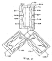
- Fig. 2 is a circuit diagram of a stator embodying the invention.
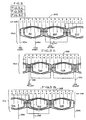
- Fig. 3 is a schematic diagram representing a first winding pattern for a stator embodying the invention.
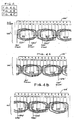
- Fig. 4 is a schematic diagram representing a second winding pattern for a stator embodying the invention.
- a system 100 embodying the invention is shown in an exploded view in Fig. 1.
- the system 100 generally includes a controller 115 (shown in phantom) and a three-phase induction starter motor/generator 120.
- the controller 115 is connected to a twelve-volt direct current (DC) battery (not shown) and provides a substantially alternating current (AC) three-phase signal to the motor 120.
- the three-phase signal to the motor 120 activates the motor 120 allowing the motor 120 to start an engine (not shown). Once the engine has started and is running at a sufficient speed, the motor 120 may be used as a generator.
- the engine commutates the motor 120 creating a substantially AC three-phase signal.
- the created three-phase signal is applied to the controller 115 for charging the DC power source and/or is applied to any internal or external devices connected to the controller (e.g., vehicle headlights or through a 120 volt AC inverter).
- a controller suitable for use with the present invention is shown in U.S. Patent Application No. 60/184,525, filed on February 24, 2000, the disclosure of which is incorporated by reference herein. Of course other controllers and other power sources that provide a three-phase signal can be used with the system 100.
- the motor 120 includes a rotor 125 (shown in phantom) that is coaxially aligned with a stator 130.
- the rotor 125 includes a first central opening 132 for receiving a drive shaft (not shown) of the engine.
- the stator 130 is excited such that it induces the rotor 125 to rotate.
- the drive shaft coupled to the rotor 125 also rotates. If the rotation of the drive shaft results in a sufficient torque to "turn over" the engine, then the engine will start. After the engine starts and is running at a running speed, the controller 115 switches to the generating mode.
- a rotor suitable for use with the present invention is a flywheel-rotor shown in U.S. Patent Application No. 09/442,560 filed on November 18, 1999, the disclosure of which is incorporated by reference herein. Of course other rotors can be can be used with the motor 120.
- the motor 120 includes a stator 130 with a second central opening 135.
- the stator is mounted on an engine frame (not shown) such that the second central opening 135 receives a portion of the rotor 125 and that the rotor 125 is allowed to rotate around the stator 130.
- the stator 130 includes a magnetically permeable stator core 140.
- the core 140 is of generally cylindrical shape formed by a plurality of stacked laminations 145 mechanically interconnected together.
- the core can be a solid core formed by one magnetically permeable member.
- each lamination includes a plurality of radially-extending teeth 150 that define a plurality of cavities or slots 155 (also schematically shown in Figs. 3 and 4).
- the slots 155 receive electrical wires 160 (partially shown in Fig. 1) that are wound around one or more teeth 150 to form coils (discussed below).
- the teeth 150 form forty-eight slots 155 (Figs. 3 and 4) for receiving wire 160.
- the number of teeth 150 and, consequently, the number of slots 155 can vary depending on the application of the invention.
- slot insulators 165 made of a non-conducting material such as cardboard or paper, align the inner surfaces of the slots 155.
- Wedge insulators 167 cover the outer radial portion of the slots 155.
- the slots 155 formed by teeth 150 are open towards the outward radial portion of the stator 130.
- other stator configurations are possible including configurations with the slots of the stator teeth opening towards the radially inward portion of the stator.
- the stator 130 shown in the figures is for a three-phase induction motor/generator 120 and includes three phase windings 170, 175 and 180.
- the stator of the invention can be used with any polyphase motor/generator having any number of phase windings.
- Phase winding 170 includes a first group of coils 190 and a second group of coils 195 electrically connected in parallel.
- the coils for phase winding 190 form (m) poles 201-208 where (m) is even and (m) is at least four. For the embodiment shown, (m) is equal to 8.
- the number of poles in each group 190 and 195 is equal to (m / 2).
- the number of poles in each group 190 and 195 is represented by the number (n), and, for the embodiment shown, (n) is equal to four.
- the coils for group 190 form poles 201, 202, 203 and 204.
- the coils for group 195 form poles 205, 206, 207 and 208.
- Each coil has (x) turns where (x) is odd.
- each pole includes two coils wound in a six/five pitch configuration with each coil having three turns.
- the number of poles, the pitch configuration and the number of turns can vary depending on the application of the invention.
- the first group of coils 190 is wound in a first pattern and the second group of coils 195 is wound in a second pattern where the second pattern is different than the first pattern.
- the first pattern may have the coils forming poles 201 and 203 being wound in a clockwise direction and the coils forming poles 202 and 204 being wound in a counter-clockwise direction
- the second pattern may have the coils forming poles 205 and 207 being wound in a counter-clockwise direction and the coils forming poles 206 and 208 being wound in a clockwise direction.
- the first pattern may have the coils forming poles 201 and 203 being wound in a counter-clockwise direction and the coils forming poles 202 and 204 being wound in a clockwise direction
- the second pattern may have the coils forming poles 205 and 207 being wound in a clockwise direction and the coils forming poles 206 and 208 being wound in a counter-clockwise direction.
- Phase windings 170, 175 and 180 each have two ends. One end of each phase winding forms a lead 220, 225 and 230 that is electrically connected to the controller 115 (Fig. 1). The other end of each phase winding is electrically connected together at node 240 (also shown in Fig. 1). This results in the phase windings 170, 175 and 180 forming a Y-configuration. As shown in Fig. 1, the ends forming leads 220, 225 and 230 and the node 240 are fixed to the stator 130 by non-conductive epoxy 245. Non-conductive epoxy 245 prevents leads 220,225 and 230 and node 240 from moving.
- Fig. 3 schematically shows a first exemplary winding scheme for an eight-pole, three-phase motor/generator having coils wound with a six/five pitch configuration.
- Fig. 4 schematically shows a second exemplary winding scheme for an eight-pole, three-phase motor/generator having coils wound with a six/five pitch configuration. Because the winding of each phase winding is similar and in order to simplify Figs. 3 and 4, only phase winding 170 (Fig. 3) is shown in detail.
- the stator core 130 has a plurality of teeth which form cavities or slots 155.
- there are forty-eight slots numbered from 1 to 48. Slots 1-48 are capable of receiving wire 160 (Fig. 1) which forms phase windings 170, 175 and 180.
- a first exemplary winding scheme for phase winding 170 is shown in Fig. 3 and is as follows. First, wire 270, which forms the first group of coils 190 (also shown in Fig. 2), is placed in slot 1 such that one end of the wire 270 recedes from the slot to form part of lead 220. The other end is wound around the stator 130. The wire 270 is first wound in a clockwise direction to create two coils forming pole 201. First, the wire 270 is wound from slot 1 to slot 6 and then back to slot 1 for two complete windings or turns. After completion of the second turn, the wire 270 is wound from slot 1 to slot 6 which completes the first coil forming pole 201. Next, the wire 270 is wound from slot 6 to slot 2.
- the wire 270 is wound in a clockwise direction to create the second coil forming pole 201.
- the wire 270 is wound from slot 2 to slot 7 and then back to slot 2 for two complete turns.
- the wire 270 is wound from slot 2 to slot 7 which completes the second coil for pole 201.
- the winding configuration just described is called a six/five pitch configuration with each coil having three turns.
- the six/five pitch configuration results because, for the first coil, each turn spans six slots from slot 1 to slot 6. After completing the first coil, the wire 270 spans five slots from slot 6 back to slot 2. After returning back to slot 2, each turn of the second coil spans six slots from slot 2 to slot 7. Therefore, the half-turn between the first and second coil is five slots and the turns for each coil spans six slots, which is typically referred to as a six/five pitch configuration.
- the wire 270 is wound from slot 7 to slot 13. From slot 13, the wire 270 is wound in a counter-clockwise direction to create two coils forming pole 202. First, the wire 270 is wound from slot 13 to slot 8 and then back to slot 13 for two complete turns. After completion of the second turn, the wire 270 is wound from slot 13 to slot 8 which completes the first coil forming pole 202. Next, the wire 270 is wound from slot 8 to slot 12. From slot 12 the wire 270 is wound in a counter-clockwise direction to create the second coil forming pole 202. First, the wire 270 is wound from slot 12 to slot 7 and then back to slot 12 for two complete turns. After completion of the second turn, the wire 270 is wound from slot 12 to slot 7 which completes the second coil forming pole 202. Similar to pole 201, the winding configuration just described is a six/five pitch configuration with each coil having three turns.
- the wire 270 is wound from slot 7 to slot 13. From slot 13, the wire 270 is wound in a clockwise direction to create two coils forming pole 203. First, the wire 270 is wound from slot 13 to slot 18 and then back to slot 13 for two complete turns. After completion of the second turn, the wire 270 is wound from slot 13 to slot 18 which completes the first coil forming pole 203. Next, the wire 270 is wound from slot 18 to slot 14. From slot 14 the wire 270 is wound in a clockwise direction to create the second coil forming pole 203. First, the wire 270 is wound from slot 14 to slot 19 and then back to slot 14 for two complete turns. After completion of the second turn, the wire 270 is wound from slot 14 to slot 19 which completes the second coil forming pole 203. Similar to pole 201, the winding configuration just described is a six/five pitch configuration with each coil having three turns.
- the wire 270 is wound from slot 19 to slot 25. From slot 25, the wire 270 is wound in a counter-clockwise direction to create two coils forming pole 204. First, the wire 270 is wound from slot 25 to slot 20 and then back to slot 25 for two complete turns. After completion of the second turn, the wire 270 is wound from slot 25 to slot 20 which completes the first coil forming pole 204. Next, the wire 270 is wound from slot 20 to slot 24. From slot 24 the wire 270 is wound in a counter-clockwise direction to create the second coil forming pole 204. First, the wire 270 is wound in from slot 24 to slot 19 and then back to slot 24 for two complete turns.
- the wire 270 is wound from slot 24 to slot 19 which completes the second coil forming pole 204. Similar to pole 201, the winding configuration just described is a six/five pitch configuration having three turns. The wire 270 then exits the stator core at slot 19 which results in the finish of the first group of coils 190. The wire 270 is then cut to be sufficiently long enough to electronically connect first wire 270 to the other wires at node 240 (described below).
- Second wire 275 which forms the group of coils 195, is placed in slot 31 such that one end of the wire 275 sufficiently recedes from the slot 31 to be connected with the other wires at node 240 (described below). The other end is wound around the stator 130.
- the wire 275 is wound in a counter-clockwise direction from slot 31 to slot 26 and then back to slot 31 for two complete turns. After completion of the second turn, the wire 275 is wound from slot 31 to slot 26 which completes the first coil forming pole 205.
- the wire 275 is wound from slot 26 to slot 30. From slot 30 the wire 275 is wound in a counter-clockwise direction to create the second coil forming pole 205.
- the wire 275 is wound from slot 30 to slot 25 and then back to slot 30 for two complete turns. After completion of the second turn, the wire 275 is wound from slot 30 to slot 25 which completes the second coil for pole 205. Similar to pole 205, the winding configuration just described is a six/five pitch configuration having three turns.
- the wire 275 is wound from slot 25 to slot 31. From slot 31, the wire 275 is wound in a clockwise direction to create two coils forming pole 206. First, the wire 275 is wound from slot 31 to slot 36 and then back to slot 31 for two complete turns. After completion of the second turn, the wire 275 is wound from slot 31 to slot 36 which completes the first coil forming pole 206. Next, the wire 275 is wound from slot 36 to slot 32. From slot 32 the wire 275 is wound in a clockwise direction to create the second coil forming pole 206. First, the wire 275 is wound from slot 32 to slot 37 and then back to slot 32 for two complete turns. After completion of the second turn, the wire 275 is wound from slot 32 to slot 37 which completes the second coil forming pole 206. Similar to pole 201, the winding configuration just described is a six/five pitch configuration with each coil having three turns.
- the wire 275 is wound from slot 37 to slot 43. From slot 43, the wire 275 is wound in a counter-clockwise direction to create two coils forming pole 207. First, the wire 275 is wound from slot 43 to slot 38 and then back to slot 43 for two complete turns. After completion of the second turn, the wire 275 is wound from slot 43 to slot 38 which completes the first coil forming pole 207. Next, the wire 275 is wound from slot 38 to slot 42. From slot 42 the wire 275 is wound in a counter-clockwise direction to create the second coil forming pole 207. First, the wire 275 is wound from slot 42 to slot 37 and then back to slot 42 for two complete turns. After completion of the second turn, the wire 275 is wound from slot 42 to slot 37 which completes the second coil forming pole 207. Similar to pole 201, the winding configuration just described is a six/five pitch configuration with each coil having three turns.
- the wire 275 is wound from slot 37 to slot 43. From slot 43, the wire 275 is wound in a clockwise direction to create two coils forming pole 208. First, the wire 275 is wound from slot 43 to slot 48 and then back to slot 43 for two complete turns. After completion of the second turn, the wire 275 is wound from slot 43 to slot 48 which completes the first coil forming pole 208. Next, the wire 275 is wound from slot 48 to slot 44. From slot 44 the wire 275 is wound in a clockwise direction to create the second coil forming pole 208. First, the wire 275 is wound from slot 44 to slot 1 and then back to slot 44 for two complete turns.
- the wire 275 is wound from slot 44 to slot 1 which completes the second coil forming pole 208. Similar to pole 201, the winding configuration just described is a six/five pitch configuration having three turns. The second wire 275 then exits the stator core at slot 1 which results in the finish of the second group of coils 195.
- the stator does not require "jumper wire” to make the electrical connections to form lead wire 220. Removing the "jumper wire” reduces the complexity in winding the phase windings, reduces the number of required connections for the phase winding, and reduces the cost of manufacturing the stator 130.
- Phase winding 175 is wound similar to phase winding 170. However, instead of starting third wire 280 (shown in phantom) forming the third group of coils 245 (also shown in Fig. 2) in slot 1, wire 280 starts in slot 5. This results in wire 280 finishing in slot 23 (not shown). Similarly, rather than starting fourth wire 285 (shown in phantom) forming the fourth group of coils 250 (also shown in Fig. 2) in slot 31, fourth wire 285 starts in slot 35. This results in wire 285 finishing in slot 5 (not shown).
- Phase winding 180 is wound similar to phase winding 170. However, instead of starting fifth wire 290 (shown in phantom) forming the fifth group of coils 255 (also shown in Fig. 2) in slot 1, wire 290 starts in slot 9. This results in wire 290 finishing in slot 27 (not shown). Similarly, rather than starting sixth wire 295 (shown in phantom) forming the sixth group of coils 260 (also shown in Fig. 2) in slot 31, sixth wire 295 starts in slot 39. This results in wire 295 finishing in slot 9 (not shown).
- phase windings (not shown) can be wound on the stator.
- the second set of phase windings is wound on top of phase windings 170, 175 and 180.
- the wires at slot 1 are electrically connected together to form lead 220
- the wires at slot 5 are electrically connected together to form lead 225
- the wires at slot 9 are electrically connected together to form lead 230.
- the leads 220, 225 and 230 are electrically connected to the controller 115 (Fig. 1).
- the wires in slots 19, 23, 27, 31, 35 and 39 are electrically connected together to form node 240.
- the resulting electric circuit is schematically shown in Fig. 2.
- a second exemplary winding scheme for phase winding 170' is shown in Fig. 4.
- the winding scheme shown in Fig. 4 may be used in alternative to the winding scheme shown in Fig. 3.
- the winding scheme shown in Fig. 4 is used with winding machinery that is unable to index backwards.
- a winding machine needs to be able to index backwards when creating the six/five pitch configuration for poles 202, 204, 205 and 207.
- the first coil of pole 202 is wound in slots 8 and 13 (Fig. 3) and the second coil of pole 202 is wound in slots 7 and 12. Going from the first coil of pole 202 to the second coil of pole 202 requires a winding machine to index backwards.
- the winding scheme shown in Fig. 4 always indexes forward when creating the six/five pitch configuration for poles 201'-208'.
- wire 270' which forms the first group of coils 190' (also shown in Fig. 2), is placed in slot 1 such that one end of the wire 270' recedes from the slot to form part of lead 220'. The other end is wound around the stator 130'.
- the wire 270' is first wound in a clockwise direction to create two coils forming pole 201'. First, the wire 270' is wound from slot 1 to slot 6 and then back to slot 1 for two complete windings or turns. After completion of the second turn, the wire 270' is wound from slot 1 to slot 6 which completes the first coil forming pole 201'. Next, the wire 270' is wound from slot 6 to slot 2.
- the wire 270' is wound in a clockwise direction to create the second coil forming pole 201'.
- the wire 270' is wound from slot 2 to slot 7 and then back to slot 2 for two complete turns. After completion of the second turn, the wire 270' is wound from slot 2 to slot 7 which completes the second coil for pole 201'.
- the wire 270' is wound from slot 7 to slot 12. From slot 12, the wire 270' is wound in a counter-clockwise direction to create two coils forming pole 202'. First, the wire 270' is wound from slot 12 to slot 7 and then back to slot 12 for two complete turns. After completion of the second turn, the wire 270' is wound from slot 12 to slot 7 which completes the first coil forming pole 202'. Next, the wire 270' is wound from slot 7 to slot 13. From slot 13 the wire 270' is wound in a counter-clockwise direction to create the second coil forming pole 202'. First, the wire 270' is wound from slot 13 to slot 8 and then back to slot 13 for two complete turns. After completion of the second turn, the wire 270' is wound from slot 13 to slot 8 which completes the second coil forming pole 202'.
- the wire 270' is wound from slot 8 to slot 13. From slot 13, the wire 270' is wound in a clockwise direction to create two coils forming pole 203'. First, the wire 270' is wound from slot 13 to slot 18 and then back to slot 13 for two complete turns. After completion of the second turn, the wire 270' is wound from slot 13 to slot 18 which completes the first coil forming pole 203'. Next, the wire 270' is wound from slot 18 to slot 14. From slot 14 the wire 270' is wound in a clockwise direction to create the second coil forming pole 203'. First, the wire 270' is wound from slot 14 to slot 19 and then back to slot 14 for two complete turns. After completion of the second turn, the wire 270' is wound from slot 14 to slot 19 which completes the second coil forming pole 203'.
- the wire 270' is wound from slot 19 to slot 24. From slot 24, the wire 270' is wound in a counter-clockwise direction to create two coils forming pole 204'. First, the wire 270' is wound from slot 24 to slot 19 and then back to slot 24 for two complete turns. After completion of the second turn, the wire 270' is wound from slot 24 to slot 19 which completes the first coil forming pole 204'. Next, the wire 270' is wound from slot 19 to slot 25. From slot 25 the wire 270' is wound in a counter-clockwise direction to create the second coil forming pole 204'. First, the wire 270' is wound in from slot 25 to slot 20 and then back to slot 25 for two complete turns.
- the wire 270' is wound from slot 25 to slot 20 which completes the second coil forming pole 204'.
- the wire 270' then exits the stator core at slot 20 which results in the finish of the first group of coils 190'.
- the wire 270' is then cut to be sufficiently long enough to electronically connect first wire 270' to the other wires at node 240'.
- Second wire 275' which forms the group of coils 195', is placed in slot 30 such that one end of the wire 275' sufficiently recedes from the slot 30 to be connected with the other wires at node 240'. The other end is wound around the stator 130'.
- the wire 275' is wound in a counter-clockwise direction from slot 30 to slot 25 and then back to slot 30 for two complete turns.
- the wire 275' is wound from slot 30 to slot 25 which completes the first coil forming pole 205'.
- the wire 275' is wound from slot 25 to slot 31.
- the wire 275' is wound in a counter-clockwise direction to create the second coil forming pole 205'.
- the wire 275' is wound from slot 31 to slot 26 and then back to slot 31 for two complete turns.
- the wire 275' is wound from slot 31 to slot 26 which completes the second coil for pole 205'.
- the wire 275' is wound from slot 26 to slot 31. From slot 31, the wire 275' is wound in a clockwise direction to create two coils forming pole 206'. First, the wire 275' is wound from slot 31 to slot 36 and then back to slot 31 for two complete turns. After completion of the second turn, the wire 275' is wound from slot 31 to slot 36 which completes the first coil forming pole 206'. Next, the wire 275' is wound from slot 36 to slot 32. From slot 32 the wire 275' is wound in a clockwise direction to create the second coil forming pole 206'. First, the wire 275' is wound from slot 32 to slot 37 and then back to slot 32 for two complete turns. After completion of the second turn, the wire 275' is wound from slot 32 to slot 37 which completes the second coil forming pole 206'.
- the wire 275' is wound from slot 37 to slot 42. From slot 42, the wire 275' is wound in a counter-clockwise direction to create two coils forming pole 207'. First, the wire 275' is wound from slot 42 to slot 37 and then back to slot 42 for two complete turns. After completion of the second turn, the wire 275' is wound from slot 42 to slot 37 which completes the first coil forming pole 207'. Next, the wire 275' is wound from slot 37 to slot 43. From slot 43 the wire 275' is wound in a counter-clockwise direction to create the second coil forming pole 207'. First, the wire 275' is wound from slot 43 to slot 38 and then back to slot 43 for two complete turns. After completion of the second turn, the wire 275' is wound from slot 43 to slot 38 which completes the second coil forming pole 207'.
- the wire 275' is wound from slot 38 to slot 43. From slot 43, the wire 275' is wound in a clockwise direction to create two coils forming pole 208'. First, the wire 275' is wound from slot 43 to slot 48 and then back to slot 43 for two complete turns. After completion of the second turn, the wire 275' is wound from slot 43 to slot 48 which completes the first coil forming pole 208'. Next, the wire 275' is wound from slot 48 to slot 44. From slot 44 the wire 275' is wound in a clockwise direction to create the second coil forming pole 208'. First, the wire 275' is wound from slot 44 to slot 1 and then back to slot 44 for two complete turns.
- the wire 275' is wound from slot 44 to slot 1 which completes the second coil forming pole 208'.
- the second wire 275' then exits the stator core at slot 1 which results in the finish of the second group of coils 195'.
- one end of each wire 270' and 275' is disposed in the same slot (i.e., slot 1). Since one end of each wire ends in the same slot, the stator does not require "jumper wire” to make the electrical connections to form lead wire 220'. Removing the "jumper wire” reduces the complexity in winding the phase windings, reduces the number of required connections for the phase winding, and reduces the cost of manufacturing the stator 130'.
- Phase winding 175' is wound similar to phase winding 170'. However, instead of starting third wire 280' (shown in phantom) forming the third group of coils 245' (also shown in Fig. 2) in slot 1, wire 280' starts in slot 5. This results in wire 280' finishing in slot 24 (not shown). Similarly, rather than starting fourth wire 285' (shown in phantom) forming the fourth group of coils 250' (also shown in Fig. 2) in slot 30, fourth wire 285' starts in slot 34. This results in wire 285' finishing in slot 5 (not shown).
- Phase winding 180' is wound similar to phase winding 170'. However, instead of starting fifth wire 290' (shown in phantom) forming the fifth group of coils 255 (also shown in Fig. 2) in slot 1, wire 290' starts in slot 9. This results in wire 290' finishing in slot 28 (not shown). Similarly, rather than starting sixth wire 295' (shown in phantom) forming the sixth group of coils 260' (also shown in Fig. 2) in slot 30, sixth wire 295' starts in slot 38. This results in wire 295' finishing in slot 9 (not shown).
- phase windings (not shown) can be wound on the stator.
- the second set of phase windings is wound on top of phase windings 170', 175' and 180'.
- the wires at slot 1 are electrically connected together to form lead 220'
- the wires at slot 5 are electrically connected together to form lead 225'
- the wires at slot 9 are electrically connected together to form lead 230'.
- the leads 220', 225' and 230' are electrically connected to the controller 115' (Fig. 1).
- the wires in slots 20, 24, 28, 30, 34 and 38 are electrically connected together to form node 240'.
- the resulting electric circuit is schematically shown in Fig. 2.
- the present invention provides an electric motor with a half-integer winding.
Applications Claiming Priority (4)
| Application Number | Priority Date | Filing Date | Title |
|---|---|---|---|
| US18452500P | 2000-02-24 | 2000-02-24 | |
| US184525P | 2000-02-24 | ||
| US774649 | 2001-02-01 | ||
| US09/774,649 US6472790B2 (en) | 2000-02-24 | 2001-02-01 | Stator for an electric motor/generator with a half-integer winding |
Publications (3)
| Publication Number | Publication Date |
|---|---|
| EP1128523A2 true EP1128523A2 (fr) | 2001-08-29 |
| EP1128523A3 EP1128523A3 (fr) | 2003-07-09 |
| EP1128523B1 EP1128523B1 (fr) | 2005-07-27 |
Family
ID=26880212
Family Applications (1)
| Application Number | Title | Priority Date | Filing Date |
|---|---|---|---|
| EP01301378A Expired - Lifetime EP1128523B1 (fr) | 2000-02-24 | 2001-02-16 | Stator pour moteur/générateur électrique avec un nombre mi-entier de spires |
Country Status (3)
| Country | Link |
|---|---|
| US (1) | US6472790B2 (fr) |
| EP (1) | EP1128523B1 (fr) |
| DE (1) | DE60112146T2 (fr) |
Cited By (2)
| Publication number | Priority date | Publication date | Assignee | Title |
|---|---|---|---|---|
| CN103683607A (zh) * | 2012-09-24 | 2014-03-26 | 北京佩特来电器有限公司 | 能够调整定子跨线的起动机及调整起动机输出特性的方法 |
| CN109075638A (zh) * | 2016-04-28 | 2018-12-21 | 日立汽车系统工程株式会社 | 旋转电机 |
Families Citing this family (28)
| Publication number | Priority date | Publication date | Assignee | Title |
|---|---|---|---|---|
| US6349463B1 (en) * | 1999-09-30 | 2002-02-26 | Reliance Electric Technologies, Llc | Method of making an electric motor stator assembly |
| JP2001275325A (ja) * | 2000-03-27 | 2001-10-05 | Honda Motor Co Ltd | 電動パワーステアリング装置 |
| DE10036289A1 (de) * | 2000-07-26 | 2002-02-07 | Bosch Gmbh Robert | Elektronisch kommutierte elektrische Maschine, insbesondere Motor |
| JP3621635B2 (ja) * | 2000-08-10 | 2005-02-16 | 三菱電機株式会社 | 回転電機 |
| DE10127364A1 (de) * | 2001-06-06 | 2003-01-09 | Siemens Ag | Wicklung |
| US6844648B2 (en) * | 2001-09-28 | 2005-01-18 | Reliance Electric Technologies, Llc | Electric motor stator and motor incorporating same |
| US6724110B2 (en) * | 2001-12-31 | 2004-04-20 | Visteon Global Technologies, Inc. | Reluctance generator for an eddy current braking system |
| US7576508B2 (en) * | 2003-01-30 | 2009-08-18 | Honeywell International Inc. | Gas turbine engine starter generator with AC generator and DC motor modes |
| JP4007207B2 (ja) * | 2003-02-12 | 2007-11-14 | 株式会社デンソー | 車両用交流発電機 |
| US7389837B2 (en) * | 2003-10-20 | 2008-06-24 | General Motors Corporation | Electric power control system for a hybrid vehicle |
| US7235906B2 (en) * | 2004-05-10 | 2007-06-26 | Airex Corporation | Magnetic bearing using displacement winding techniques |
| US7078826B2 (en) * | 2004-08-17 | 2006-07-18 | Honeywell International, Inc. | Hybrid gas turbine engine starter-generator |
| US7075206B1 (en) | 2005-02-07 | 2006-07-11 | Visteon Global Technologies, Inc. | Vehicle alternator stator winding having dual slot configuration |
| WO2006107623A1 (fr) * | 2005-04-06 | 2006-10-12 | General Motors Global Technology Operations, Inc. | Optimisation d'architecture de systeme pour selection de gamme de transmission electronique |
| US7005772B1 (en) | 2005-04-06 | 2006-02-28 | Visteon Global Technologies, Inc. | Stator winding having two slots per phase per pole |
| JP4665595B2 (ja) * | 2005-04-28 | 2011-04-06 | トヨタ自動車株式会社 | 回転電機の巻線構造 |
| JP4617992B2 (ja) * | 2005-04-28 | 2011-01-26 | トヨタ自動車株式会社 | 回転電機の巻線構造 |
| US7615899B2 (en) * | 2005-12-13 | 2009-11-10 | Mitsubishi Electric Corporation | Magneto generator with arrangements for lead wires of three-phase windings |
| US20090021100A1 (en) * | 2007-07-19 | 2009-01-22 | Sheng-Chung Lee | Stator Structure of External-rotor Motor |
| ATE533224T1 (de) * | 2007-10-30 | 2011-11-15 | Thyssenkrupp Presta Ag | Statorwicklung für elektromotor |
| US8901797B2 (en) * | 2008-01-29 | 2014-12-02 | Ford Global Technologies, Llc | Brushless motor system for a vehicle fuel pump |
| BRPI1006138A2 (pt) * | 2009-01-12 | 2016-02-23 | Redemptive Technologies Ltd | gerador elétrico de alta eficiência de arrasto diminuído |
| US20120206076A1 (en) * | 2009-10-28 | 2012-08-16 | Shouichi Tanaka | Motor-driving apparatus for variable-speed motor |
| JP5620806B2 (ja) | 2010-12-22 | 2014-11-05 | オークマ株式会社 | 電動機 |
| US8829742B2 (en) * | 2013-01-04 | 2014-09-09 | Xinzhang Wu | High efficiency permanent magnet machine |
| JP6184387B2 (ja) * | 2014-09-30 | 2017-08-23 | 株式会社東芝 | 回転電機、及び回転電機の製造方法 |
| US9641112B2 (en) * | 2014-12-10 | 2017-05-02 | Clark Equipment Company | Protection method for a generator |
| WO2019116918A1 (fr) * | 2017-12-14 | 2019-06-20 | アイシン・エィ・ダブリュ株式会社 | Stator |
Citations (6)
| Publication number | Priority date | Publication date | Assignee | Title |
|---|---|---|---|---|
| CH219269A (de) * | 1940-02-15 | 1942-01-31 | Hermes Patentverwertungs Gmbh | Polumschaltbare Bruchlochwicklung für elektrische Maschinen. |
| US4404486A (en) * | 1980-12-24 | 1983-09-13 | General Electric Company | Star connected air gap polyphase armature having limited voltage gradients at phase boundaries |
| US4451751A (en) * | 1981-10-16 | 1984-05-29 | Siemens Aktiengesellschaft | Three-phase winding for a high-voltage machine |
| US4755702A (en) * | 1986-01-08 | 1988-07-05 | Nec Corporation | Three-phase induction motor |
| US5794884A (en) * | 1992-09-23 | 1998-08-18 | Globe Products Inc. | Stator winding apparatus with selectively movable coil former |
| EP0991164A2 (fr) * | 1998-10-02 | 2000-04-05 | Siemens Aktiengesellschaft | Machine électrique sans balai, notamment démarreur-alternateur connectable à un réseau d'alimentation élèctrique de bord d'un véhicule |
Family Cites Families (19)
| Publication number | Priority date | Publication date | Assignee | Title |
|---|---|---|---|---|
| US2778962A (en) * | 1954-02-11 | 1957-01-22 | Gen Electric | Armature winding with four parallels per phase |
| US3408517A (en) * | 1966-02-23 | 1968-10-29 | Gen Electric | Multiple circuit winding patterns for polyphase dynamoelectric machines |
| US3514650A (en) | 1968-10-02 | 1970-05-26 | Us Army | Variable reluctance synchronal dynamo |
| US3601642A (en) * | 1970-01-22 | 1971-08-24 | Gen Electric | Multi-three phase winding with interchanged circuit sequence |
| US3652888A (en) * | 1971-03-18 | 1972-03-28 | Gen Electric | Two pole, 45 slot, three circuit dynamoelectric machine winding pattern |
| US4371802A (en) | 1980-06-12 | 1983-02-01 | Morrill Wayne J | Half-pitch capacitor induction motor |
| JPS5914336A (ja) | 1982-07-14 | 1984-01-25 | Hitachi Ltd | 回転電気機械 |
| GB8501215D0 (en) | 1985-01-17 | 1985-02-20 | Dowty Fuel Syst Ltd | Alternating-current electrical generator |
| US4752707A (en) | 1986-02-06 | 1988-06-21 | Morrill Wayne J | Three-phase, one-third pitch motor |
| JPH0721078Y2 (ja) * | 1988-07-21 | 1995-05-15 | 多摩川精機株式会社 | 電動機 |
| US4947072A (en) * | 1988-10-21 | 1990-08-07 | A.O. Smith Corporation | Stator winding for two-pole dynamoelectric induction machines |
| US4983867A (en) | 1990-06-28 | 1991-01-08 | Japan Servo Co., Ltd. | Hybrid-type stepping motor |
| US5057731A (en) | 1990-08-15 | 1991-10-15 | Xolox Corportion | Simplified spindle motor for disc drive |
| US5714821A (en) * | 1994-02-16 | 1998-02-03 | Marathon Electric Mfg. Corp. | Alternating current generator with direct connected exciter winding |
| US5852334A (en) | 1995-10-19 | 1998-12-22 | Tridelta Industries, Inc. | Staggered pole switched reluctance motor |
| KR100200667B1 (ko) | 1996-01-18 | 1999-06-15 | 윤종용 | 브러시리스 직류모터 |
| US5825111A (en) | 1996-11-12 | 1998-10-20 | Emerson Electric Co. | Single-phase induction motor 4/6 pole common winding connection with magnetic motive force symmetrically distributed |
| US5811905A (en) | 1997-01-07 | 1998-09-22 | Emerson Electric Co. | Doubly-fed switched reluctance machine |
| FR2765044B1 (fr) * | 1997-06-20 | 2004-02-13 | Jeumont Ind | Procede de bobinage en deux plans d'encoche pour une machine electrique tournante |
-
2001
- 2001-02-01 US US09/774,649 patent/US6472790B2/en not_active Expired - Fee Related
- 2001-02-16 DE DE60112146T patent/DE60112146T2/de not_active Expired - Fee Related
- 2001-02-16 EP EP01301378A patent/EP1128523B1/fr not_active Expired - Lifetime
Patent Citations (6)
| Publication number | Priority date | Publication date | Assignee | Title |
|---|---|---|---|---|
| CH219269A (de) * | 1940-02-15 | 1942-01-31 | Hermes Patentverwertungs Gmbh | Polumschaltbare Bruchlochwicklung für elektrische Maschinen. |
| US4404486A (en) * | 1980-12-24 | 1983-09-13 | General Electric Company | Star connected air gap polyphase armature having limited voltage gradients at phase boundaries |
| US4451751A (en) * | 1981-10-16 | 1984-05-29 | Siemens Aktiengesellschaft | Three-phase winding for a high-voltage machine |
| US4755702A (en) * | 1986-01-08 | 1988-07-05 | Nec Corporation | Three-phase induction motor |
| US5794884A (en) * | 1992-09-23 | 1998-08-18 | Globe Products Inc. | Stator winding apparatus with selectively movable coil former |
| EP0991164A2 (fr) * | 1998-10-02 | 2000-04-05 | Siemens Aktiengesellschaft | Machine électrique sans balai, notamment démarreur-alternateur connectable à un réseau d'alimentation élèctrique de bord d'un véhicule |
Cited By (4)
| Publication number | Priority date | Publication date | Assignee | Title |
|---|---|---|---|---|
| CN103683607A (zh) * | 2012-09-24 | 2014-03-26 | 北京佩特来电器有限公司 | 能够调整定子跨线的起动机及调整起动机输出特性的方法 |
| CN103683607B (zh) * | 2012-09-24 | 2015-12-23 | 北京佩特来电器有限公司 | 能够调整定子跨线的起动机及调整起动机输出特性的方法 |
| CN109075638A (zh) * | 2016-04-28 | 2018-12-21 | 日立汽车系统工程株式会社 | 旋转电机 |
| CN109075638B (zh) * | 2016-04-28 | 2020-11-10 | 日立汽车系统工程株式会社 | 旋转电机 |
Also Published As
| Publication number | Publication date |
|---|---|
| EP1128523B1 (fr) | 2005-07-27 |
| DE60112146T2 (de) | 2006-05-24 |
| US6472790B2 (en) | 2002-10-29 |
| EP1128523A3 (fr) | 2003-07-09 |
| DE60112146D1 (de) | 2005-09-01 |
| US20010033116A1 (en) | 2001-10-25 |
Similar Documents
| Publication | Publication Date | Title |
|---|---|---|
| US6472790B2 (en) | Stator for an electric motor/generator with a half-integer winding | |
| EP1102385B1 (fr) | Machine électrique tournante pour véhicule | |
| KR101730525B1 (ko) | 브러시없는 동기식 모터 | |
| JP4319961B2 (ja) | 回転電機及び電機巻線 | |
| US8264114B2 (en) | Electric rotating machine having improved stator coil arrangement for reducing magnetic noise and torque ripple | |
| US6864667B2 (en) | Stator winding pattern for reduced magnetic noise | |
| US11605989B2 (en) | Stator winding with alternating winding pitches | |
| JP5214646B2 (ja) | 回転電機 | |
| US20080185933A1 (en) | Three-phase rotating electrical machine | |
| US11557933B2 (en) | Electric machine with distributed winding having double cross end loops | |
| US4038575A (en) | Multi-phase generator | |
| EP0364510A4 (fr) | Connexions compactes pour enroulements d'induits interdisperses. | |
| CN105659472B (zh) | 电机 | |
| GB2582941A (en) | A stator winding arrangement | |
| CN113412569B (zh) | 具有带有交叉端部回路的平行路径的分布式定子绕组 | |
| US11128189B2 (en) | Electric machine stator with compact configuration | |
| JP4042676B2 (ja) | 回転電機用電機子 | |
| JP2006158174A (ja) | 回転電機及びその製造方法 | |
| CN113452172A (zh) | 具有串联的线圈绕组的定子绕组系统 | |
| CN106787577B (zh) | 用作内燃机的起动发电机的改进的电机 | |
| RU2072611C1 (ru) | Реактивный двигатель с электромагнитной редукцией | |
| SU1457101A1 (ru) | Редукторный электродвигатель | |
| CN115149849A (zh) | 旋转电机装置 | |
| RU94018159A (ru) | Реактивный двигатель с электромагнитной редукцией | |
| WO2016016874A2 (fr) | Moteur électrique à aimant permanent et générateur et moteur hybride comprenant celui-ci dans un scooter |
Legal Events
| Date | Code | Title | Description |
|---|---|---|---|
| PUAI | Public reference made under article 153(3) epc to a published international application that has entered the european phase |
Free format text: ORIGINAL CODE: 0009012 |
|
| AK | Designated contracting states |
Kind code of ref document: A2 Designated state(s): AT BE CH CY DE DK ES FI FR GB GR IE IT LI LU MC NL PT SE TR |
|
| AX | Request for extension of the european patent |
Free format text: AL;LT;LV;MK;RO;SI |
|
| PUAL | Search report despatched |
Free format text: ORIGINAL CODE: 0009013 |
|
| RIC1 | Information provided on ipc code assigned before grant |
Ipc: 7H 02K 3/28 B Ipc: 7H 02K 17/12 B Ipc: 7H 02K 3/12 A |
|
| AK | Designated contracting states |
Designated state(s): AT BE CH CY DE DK ES FI FR GB GR IE IT LI LU MC NL PT SE TR |
|
| AX | Request for extension of the european patent |
Extension state: AL LT LV MK RO SI |
|
| 17P | Request for examination filed |
Effective date: 20031224 |
|
| AKX | Designation fees paid |
Designated state(s): DE FR GB IT |
|
| GRAP | Despatch of communication of intention to grant a patent |
Free format text: ORIGINAL CODE: EPIDOSNIGR1 |
|
| GRAS | Grant fee paid |
Free format text: ORIGINAL CODE: EPIDOSNIGR3 |
|
| GRAA | (expected) grant |
Free format text: ORIGINAL CODE: 0009210 |
|
| AK | Designated contracting states |
Kind code of ref document: B1 Designated state(s): DE FR GB IT |
|
| REG | Reference to a national code |
Ref country code: GB Ref legal event code: FG4D |
|
| REF | Corresponds to: |
Ref document number: 60112146 Country of ref document: DE Date of ref document: 20050901 Kind code of ref document: P |
|
| PGFP | Annual fee paid to national office [announced via postgrant information from national office to epo] |
Ref country code: IT Payment date: 20060228 Year of fee payment: 6 |
|
| PGFP | Annual fee paid to national office [announced via postgrant information from national office to epo] |
Ref country code: FR Payment date: 20060301 Year of fee payment: 6 |
|
| PGFP | Annual fee paid to national office [announced via postgrant information from national office to epo] |
Ref country code: DE Payment date: 20060331 Year of fee payment: 6 |
|
| ET | Fr: translation filed | ||
| PLBE | No opposition filed within time limit |
Free format text: ORIGINAL CODE: 0009261 |
|
| STAA | Information on the status of an ep patent application or granted ep patent |
Free format text: STATUS: NO OPPOSITION FILED WITHIN TIME LIMIT |
|
| 26N | No opposition filed |
Effective date: 20060428 |
|
| GBPC | Gb: european patent ceased through non-payment of renewal fee |
Effective date: 20070216 |
|
| REG | Reference to a national code |
Ref country code: FR Ref legal event code: ST Effective date: 20071030 |
|
| PG25 | Lapsed in a contracting state [announced via postgrant information from national office to epo] |
Ref country code: DE Free format text: LAPSE BECAUSE OF NON-PAYMENT OF DUE FEES Effective date: 20070901 |
|
| PG25 | Lapsed in a contracting state [announced via postgrant information from national office to epo] |
Ref country code: GB Free format text: LAPSE BECAUSE OF NON-PAYMENT OF DUE FEES Effective date: 20070216 Ref country code: FR Free format text: LAPSE BECAUSE OF NON-PAYMENT OF DUE FEES Effective date: 20070228 |
|
| PGFP | Annual fee paid to national office [announced via postgrant information from national office to epo] |
Ref country code: GB Payment date: 20060223 Year of fee payment: 6 |
|
| PG25 | Lapsed in a contracting state [announced via postgrant information from national office to epo] |
Ref country code: IT Free format text: LAPSE BECAUSE OF NON-PAYMENT OF DUE FEES Effective date: 20070216 |