EP1127856B1 - Liquid cooling of glassware molds - Google Patents
Liquid cooling of glassware molds Download PDFInfo
- Publication number
- EP1127856B1 EP1127856B1 EP01104273A EP01104273A EP1127856B1 EP 1127856 B1 EP1127856 B1 EP 1127856B1 EP 01104273 A EP01104273 A EP 01104273A EP 01104273 A EP01104273 A EP 01104273A EP 1127856 B1 EP1127856 B1 EP 1127856B1
- Authority
- EP
- European Patent Office
- Prior art keywords
- coolant
- manifold
- mold
- shaft
- mold part
- Prior art date
- Legal status (The legal status is an assumption and is not a legal conclusion. Google has not performed a legal analysis and makes no representation as to the accuracy of the status listed.)
- Expired - Lifetime
Links
- 238000001816 cooling Methods 0.000 title claims description 17
- 239000007788 liquid Substances 0.000 title claims description 15
- 239000002826 coolant Substances 0.000 claims description 112
- 230000008878 coupling Effects 0.000 claims description 36
- 238000010168 coupling process Methods 0.000 claims description 36
- 238000005859 coupling reaction Methods 0.000 claims description 36
- KJLPSBMDOIVXSN-UHFFFAOYSA-N 4-[4-[2-[4-(3,4-dicarboxyphenoxy)phenyl]propan-2-yl]phenoxy]phthalic acid Chemical compound C=1C=C(OC=2C=C(C(C(O)=O)=CC=2)C(O)=O)C=CC=1C(C)(C)C(C=C1)=CC=C1OC1=CC=C(C(O)=O)C(C(O)=O)=C1 KJLPSBMDOIVXSN-UHFFFAOYSA-N 0.000 claims description 23
- 238000000034 method Methods 0.000 claims description 13
- 238000007789 sealing Methods 0.000 claims description 10
- 238000012544 monitoring process Methods 0.000 claims description 2
- 239000012530 fluid Substances 0.000 description 13
- 230000007246 mechanism Effects 0.000 description 6
- 238000007667 floating Methods 0.000 description 5
- 239000011521 glass Substances 0.000 description 5
- 230000008439 repair process Effects 0.000 description 5
- 238000012546 transfer Methods 0.000 description 4
- 230000006835 compression Effects 0.000 description 3
- 238000007906 compression Methods 0.000 description 3
- 238000000605 extraction Methods 0.000 description 3
- 238000004519 manufacturing process Methods 0.000 description 3
- 239000006060 molten glass Substances 0.000 description 3
- 230000008569 process Effects 0.000 description 3
- 238000004891 communication Methods 0.000 description 2
- 238000012423 maintenance Methods 0.000 description 2
- 238000012986 modification Methods 0.000 description 2
- 230000004048 modification Effects 0.000 description 2
- 230000002093 peripheral effect Effects 0.000 description 2
- XLYOFNOQVPJJNP-UHFFFAOYSA-N water Substances O XLYOFNOQVPJJNP-UHFFFAOYSA-N 0.000 description 2
- 229910001141 Ductile iron Inorganic materials 0.000 description 1
- ZOKXTWBITQBERF-UHFFFAOYSA-N Molybdenum Chemical compound [Mo] ZOKXTWBITQBERF-UHFFFAOYSA-N 0.000 description 1
- 229920006362 Teflon® Polymers 0.000 description 1
- 238000005299 abrasion Methods 0.000 description 1
- 230000002457 bidirectional effect Effects 0.000 description 1
- 238000007664 blowing Methods 0.000 description 1
- 238000010276 construction Methods 0.000 description 1
- 238000005336 cracking Methods 0.000 description 1
- 238000009826 distribution Methods 0.000 description 1
- 238000005516 engineering process Methods 0.000 description 1
- 230000007613 environmental effect Effects 0.000 description 1
- 230000005484 gravity Effects 0.000 description 1
- 239000000314 lubricant Substances 0.000 description 1
- 239000000463 material Substances 0.000 description 1
- 229910052750 molybdenum Inorganic materials 0.000 description 1
- 239000011733 molybdenum Substances 0.000 description 1
- 238000000465 moulding Methods 0.000 description 1
- 239000002245 particle Substances 0.000 description 1
- 238000003825 pressing Methods 0.000 description 1
- 230000000979 retarding effect Effects 0.000 description 1
- 238000007493 shaping process Methods 0.000 description 1
- 229910052710 silicon Inorganic materials 0.000 description 1
- 239000010703 silicon Substances 0.000 description 1
Images


Classifications
-
- C—CHEMISTRY; METALLURGY
- C03—GLASS; MINERAL OR SLAG WOOL
- C03B—MANUFACTURE, SHAPING, OR SUPPLEMENTARY PROCESSES
- C03B9/00—Blowing glass; Production of hollow glass articles
- C03B9/30—Details of blowing glass; Use of materials for the moulds
- C03B9/38—Means for cooling, heating, or insulating glass-blowing machines or for cooling the glass moulded by the machine
- C03B9/3875—Details thereof relating to the side-wall, body or main part of the moulds
-
- C—CHEMISTRY; METALLURGY
- C03—GLASS; MINERAL OR SLAG WOOL
- C03B—MANUFACTURE, SHAPING, OR SUPPLEMENTARY PROCESSES
- C03B9/00—Blowing glass; Production of hollow glass articles
- C03B9/30—Details of blowing glass; Use of materials for the moulds
- C03B9/34—Glass-blowing moulds not otherwise provided for
- C03B9/353—Mould holders ; Mould opening and closing mechanisms
- C03B9/3532—Mechanisms for holders of half moulds moving by rotation about a common vertical axis
Definitions
- the present invention is directed to a system for cooling molds in a glassware forming machine, and to a method of liquid cooling particularly of the blank molds and/or blow molds in an individual section machine.
- Such machines include a plurality of separate or individual manufacturing sections, each of which has a multiplicity of operating mechanisms for converting one or more charges or gobs of molten glass into hollow glass containers and transferring the containers through successive stations of the machine section.
- Each machine section includes one or more blank molds in which a glass gob is initially formed in a blowing or pressing operation, an invert arm for transferring the blanks to blow molds in which the containers are blown to final form, tongs for removing the formed containers onto a deadplate, and a sweepout mechanism for transferring molded containers from the deadplate onto a conveyor.
- U.S. Patent 4,362,544 includes a background discussion of both blow-and-blow and press-and-blow glassware forming processes, and discloses an electropneumatic individual section machine adapted for use in either process.
- Liquid cooling is known from US-A-3,887,350 and US-A- 4,142,884, the latter showing the features of the preamble to claim 1.
- a fluid such as water
- heat extraction by liquid cooling can be too rapid and uncontrolled, at least in some areas of the mold, so steps must be taken to retard heat transfer from the inner or forming surface of a mold part to the outer periphery in which the liquid cooling passages are disposed.
- Various techniques for so controlling liquid-coolant heat extraction have been proposed in the art, but have not been entirely satisfactory.
- EP 1,084,994 A US 6,412,308 B1 discloses a system and method for cooling the forming molds in a glassware forming machine, in which each mold includes a body of heat conductive construction having a central portion with a forming surface for shaping molten glass and a peripheral portion spaced radially outwardly of the central portion.
- a plurality of coolant passages extend in a spaced array around the peripheral portion of the mold body, and liquid coolant is directed through such passages for extracting heat from the body by conduction from the forming surface.
- a plurality of openings extend axially into the body radially between at least some of the liquid coolant passages and the forming surface for retarding heat transfer from the forming surface to the liquid coolant passages.
- the openings have a depth into the mold body. either part way or entirely through the mold body, coordinated with the contour of the forming surface and other manufacturing parameters to control heat transfer from the forming surface to the coolant passages.
- the openings may be wholly or partially filled with material for further tailoring heat transfer from the forming surface to the coolant passages.
- the mold body is constructed of austenitic Ni-Resist ductile iron having elevated silicon and molybdenum content. Endplates are carried by the mold body for controlling flow of coolant in multiple passes through the coolant passages.
- the mold may be either a blank mold or a blow mold.
- the presently preferred system and method of the invention direct liquid coolant to the blank or blow mold halves of a glassware forming machine through an enclosed pivotal rotary union structure, as distinguished from flexible hoses and the like.
- a coolant manifold is carried by each pivotal mold arm, and communicates with coolant inlet and outlet ports at the lower end of each mold part.
- the manifold is connected by a floating shaft seal, a rotary union assembly and a crank arm to a coolant source and coolant return in the section box of the associated IS machine section.
- Each pivotal connection - i.e., between the section box and the crank arm, between the crank arm and the rotary union assembly, and between the rotary union assembly and the floating shaft seal - comprises a bidirectional rotary union for feeding liquid coolant to the manifold and mold parts, and returning coolant from the manifold and mold parts.
- Dynamic floating O-ring seals between the coolant manifold and the mold parts, and between the coolant manifold and the floating shaft seal accommodate relative motion between these components as the mold parts are opened and closed.
- a system for cooling molds in a glassware forming machine in accordance with the presently preferred embodiment of the invention includes a pair of mold arms mounted for movement toward and away from each other, and at least one blank mold or blow mold part carried by each arm and adapted to cooperate with each other to form a glassware forming mold.
- Each of the mold parts includes at least one coolant passage having an inlet and an outlet disposed adjacent to each other at one end of the mold part.
- a coolant manifold is carried by each mold arm adjacent to the ends of the mold parts at which the coolant inlet and outlet are disposed, with each manifold having inlet and outlet coolant flow passages coupled to the inlet and outlet of the associated mold parts.
- a coolant source and a coolant return are disposed in fixed position adjacent to the mold arms, and a pivotal coupling rotary union assembly operatively connects the coolant source and return to the manifold.
- the pivotal coupling rotary union assembly includes parallel coolant flow paths for directing coolant from the source through the pivotal coupling assembly and the manifold inlet passage to the mold inlet, through the mold part, and from the mold outlet through the manifold outlet passage and the pivotal coupling assembly to the coolant return.
- the pivotal coupling rotary union assembly in the preferred embodiment of the invention includes a crank arm assembly having a first crank shaft rotatably coupled to a housing on the section box of the IS machine, a second crank shaft and a crank tie bar interconnecting the first and second crank shafts.
- the second crank shaft is rotatably received in a shaft link block, as is a manifold tie shaft having a head secured to the side wall of the manifold. Seals in the section box housing and the shaft link block surround the first and second crank shafts and the manifold tie shaft.
- Parallel coolant flow passages extend from the section box through the first crank shaft, laterally through the crank tie bar, through the second crank shaft, laterally through the shaft link block and through the manifold tie shaft and head to the coolant manifold on the mold arm.
- drain passages are formed in the shaft link block, the second and first crank shafts and the interconnecting crank tie bar, and open at each shaft between seals that engage the associated shaft, for draining by force of gravity any coolant that may leak past the seals.
- the mold parts are releasably secured to the associated mold arms by clamps that selectively engage a radial ledge at the lower end of each mold part.
- Each clamp includes a bridge carried in fixed position on the mold arm, and a lockdown clip carried beneath the bridge for rotation selectively to overlie or clear the ledge on the mold part.
- the lockdown clip may be rotated into position to overlie the mold part ledge to hold the mold part ledge on the mold arm, or to clear the mold part ledge so that the mold part may be readily removed by an operator for repair or replacement.
- a detent locking arrangement between the lockdown clip and the bridge provides for releasable locking of the lockdown clip in either the ledge-overlying or ledge-clearing position of the lockdown clip.
- a rod preferably extends from the clip through an opening in the bridge parallel to the mold part to a position adjacent to the upper edge of the mold part to facilitate rotation of the lockdown clip into and out of engagement with respect to the mold part.
- a pin on the mold arm is received in an opening on the underside of the mold part to permit limited rotation of the mold part for self-adjustment with the opposing mold part as the mold arms are brought together.
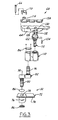
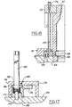
- FIGS. 1 and 2 illustrate a portion of the blow mold station 30 of one section of an individual section glassware forming machine equipped with a coolant delivery system 32 in accordance with a presently preferred embodiment of the present invention.
- a pair ofmold arms 34, 36 are pivotally mounted on a stationary bearing shaft 38, and each carry a plurality of mold parts 40.
- Each mold part 40 is adapted to cooperate with the opposing mold part carried on the opposing arm to form a mold cavity for molding an article of glassware.
- the presently preferred embodiment is illustrated in the drawings in connection with a blow mold station 30, in which each pair of mold parts 40 cooperates with a bottom mold element 42 and with each other to form a blow mold cavity.
- coolant delivery system 32 in accordance with the present invention is equally useful for cooling the blank molds at the blank mold station of an IS machine section, either a linear machine or a rotary machine.
- the coolant delivery system 32 (FIG. 1) associated with mold arm 34 will be described in detail.
- the coolant delivery system associated with mold arm 36 is a mirror image of system 32.
- station 30 is illustrated in FIGS. 1 and 2 as a station for a so-called triple gob IS machine, comprising three pairs of mold parts 40, the present invention is equally useful in conjunction with so-called single, double, quad and other types of glassware forming machines.
- a coolant manifold 44 is secured beneath mold arm 34 for movement conjointly with the mold arm.
- a plurality of clamps 46 are carried by manifold 44, each for securing an associated mold part 40 in position relative to the manifold.
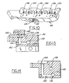
- Each clamp 46 includes a bridge 170 (FIGS. 1-2 and 17-20), having side legs secured to manifold 44 and an upper reach spaced from the opposing face of manifold 44 parallel thereto.
- a lockdown clip 172 is disposed beneath each bridge 170.
- Each clip 172 includes a body having a laterally extending finger 174 that is adapted in assembly to overlie a ledge formed by a plate 148 (FIGS. 1-2) that extends laterally outwardly from the lower end of each mold part 40.
- a pair of pockets 176, 178 are formed on the underside of bridge 170.
- a rod 180 has a lug 182 press fitted and pinned or otherwise fixedly secured to the lower end thereof. Rod 180 extends upwardly through mold arm 34 or 36 adjacent to an associated mold part 40. The upper end of each rod 180 has a hex head for engagement by an appropriate tool.
- a dowel pin 184 is press fitted or otherwise secured to a radial lobe on lug 182, and extends upwardly therefrom parallel to rod 180 for selective registry with pockets 176, 178 in bridge 170, as will be described.
- Lug 182 and the lower end of rod 180 are positioned in a pocket 186 on the body of clip 172.
- a spring 188 is captured in compression within pocket 186 beneath lug 182.
- a pin 190 extends downwardly from clip 172 coaxially with rod 180, and is received in a corresponding pocket on manifold 44 to guide rotation of clip 172.
- the lobe on lug 182 rotatably couples clip 172 to rod 170. That is, rod 180 may be rotated clockwise (FIGS. 1, 2 and 17-20) to rotate lockdown clip 172 clockwise until detent pin 184 is in registry with detent pocket 176 in bridge 170, at which point the force of spring 188 will urge pin 184 into pocket 176.
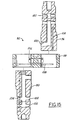
- FIGS. 21-22 illustrate a modified lockdown clamp 192.
- Each clamp 192 includes a bridge 48, having side legs secured to manifold 44 and an upper reach spaced from the opposing face of manifold 44 parallel thereto.
- a lockdown clip 50 is disposed beneath each bridge 48.
- Each clip 50 includes a body having a laterally extending finger 52 that is adapted in assembly to overlie the plate 148 that extends laterally outwardly from the lower end of each mold part 40.
- a pair of pockets 56, 58 are formed on the underside of bridge 48.
- a detent ball 60 and a coil spring 62 are captured in compression within a pocket 64 on the body of lockdown clip 50 for selective registry with detent pockets 56, 58 on the underside of bridge 48.
- a clip rod 66 is coupled to the body of each lockdown clip 50, and extends upwardly therefrom through mold arm 34 or 36 for selectively rotating clip 50 and clip finger 52 into and out of overlying engagement with the ledge 54 of the associated adjacent mold part. That is, rod 66 may be rotated clockwise to rotate lockdown clip 50 clockwise until detent ball 60 is in registry with detent pocket 56 in bridge 48, at which point the force of spring 62 will urge ball 60 into pocket 56. At this point, the finger 52 of clip 50 clears plate 148 of the associated mold body 40, so that the mold body can be lifted from the mold station for repair or replacement by an operator. When the mold body is replaced in position over a locating pin 69 (FIG. 2) on manifold 44, rod 66 and lockdown clip 50 maybe rotated counterclockwise until ball detent 60 registers with detent pocket 58 in bridge 48, at which point leg 52 overlies mold plate 148 and holds the mold in position
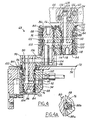
- Coolant delivery system 32 also includes a rotary union assembly 68 (FIGS. 1 and 3-5) having a section box housing 72 that is insertable into an opening in the section box 70 at each machine section.
- Section box housing 72 includes a top panel 74 and a block 76 welded or otherwise secured to the underside of panel 74.
- Block 76 has a central opening that aligns with an opening 78 in panel 74 (FIG. 3) for receiving the lower crank shaft 80 of a crank arm assembly 82.
- Shaft 80 is supported within block 76 by axially spaced bearings 84 (FIG. 4), which are enclosed by bearing cover plates 86.
- a plurality of axially spaced seals 88 are mounted in corresponding channels formed on the inside diameter of block 76 for sealing engagement with opposing lands on shaft 80.
- a pair of ports 90, 92 extend laterally through block 76, and open to the internal bore of block 76 on laterally opposed sides of the central seal 88.
- a drainage port 94 extends laterally into block 76 and opens to the central bore of the block between the two lowermost seals 88.
- Each seal 88 includes an annular Teflon (trademark) based rotary seal 88a in sliding engagement with the associated shaft, and an elastomeric O-ring 88b. O-rings 88b are in radial compression to urge seal 88a radially inwardly, and to make radially outward sealing engagement with the base of the associated seal groove.
- Crank arm assembly 82 (FIGS. 3-5 and 15) includes first or lower crank shaft 80 and a second or upper crank shaft 96 extending from opposite ends of crank tie bar 98 in opposite parallel axial directions.
- Lower and upper crank shafts 80, 96 are essentially identical, each having a pair of water flow passages 100, 102 extending axially through the mid portion of the crank shaft, and opening laterally outwardly adjacent to the ends of the crank shaft.
- a third passage 104 of reduced diameter extends axially through the mid portion of each crank shaft, and opens laterally outwardly from the crank shaft, opening and circumferential channel associated with passage 100 in lower crank shaft 80 registers with port 90 of block 76 (FIG.
- crank tie bar 98 there are a pair of longitudinal parallel passages 106, 107 (FIGS. 4, 9 and 15) that respectively register in assembly with the lateral openings of passages 100, 102 at the upper end of lower crank shaft 80, and with the associated passages at the lower end of upper crank shaft 96.
- passage 108 in crank tie bar 98 that interconnects the associated ends of drain passages 104 in lower and upper crank shafts 80, 96.
- crank shafts 80, 96 are press fitted, shrunk fit or otherwise rigidly secured to crank tie bar 98 so as to maintain alignment and sealing of the various passage ends, which is to say that crank shafts 80, 96 do not rotate within the corresponding openings of tie bar 98.
- a shaft link block 110 rotatably receives the upper end of upper crank shaft 96, and rotatably receives the lower end of a manifold tie shaft 112.
- Shaft link block 110 has a pair of parallel passages 114, 116 (FIGS. 4 and 9) that interconnect the parallel fluid passages 100, 102 of upper crank shaft 96 with the corresponding parallel fluid passages in tie shaft 112, which are identified by the same reference numerals 100, 102 to facilitate understanding.
- drain passage 104 in upper crank shaft 96 is aligned with a lateral drain passage 118 in shaft link block 110, which in turn is connected to a longitudinal drain passage 120 in the shaft link block.
- Drain passages 118, 120 in shaft link block 110 open between the lowermost and uppermost pairs of seals 88 in the shaft link block for collecting any coolant that may leak past the seals.
- Seals 88 surround upper crank shaft 96 and tie shaft 112 in link block 110, and each shaft is supported by spaced roller bearings 84 with associated bearing covers 86.
- Parallel passages 114, 116 in link block 110 open on opposed sides of the middle seal 88, and parallel passages 100, 102 in shafts 96, 112 open at corresponding axial positions on opposed sides of the center seal, as previously described.
- Tie shaft 112 has an enlarged integral head 122 (FIGS. 3-7) formed at the upper end thereof. Head 122 is secured to the sidewall of manifold 44. Passages 100, 102 in tie shaft 112 terminate within head 122 in a pair of lateral openings or ports 124, 126 respectively. These openings or ports, which are vertically or axially staggered with respect to the longitudinal dimension of tie shaft 112, register in assembly with a pair of openings or ports 128, 130 in the opposing sidewall of manifold 44. These openings 128, 130 are circumferentially enlarged at the outside surface of the manifold, and a pair of O-rings 132 (FIGS. 3 and 7) are disposed in a countersunk pocket around each opening 128, 130.
- a pair of screws 134 loosely secure tie shaft head 122 to the opposing face of manifold 44, with O-rings 132 being compressed between the opposing faces of head 122 and manifold 44.
- Manifold openings 128, 130 communicate within the body of manifold 44 with a pair of longitudinal parallel coolant passages 136, 138 that extend through the body of the manifold (FIGS. 9-14).
- a pair of side passages 140, 142 extend from respective longitudinal coolant passages 136, 138, and terminate in a pair of adjacent upwardly opening coolant ports 144, 146 at the upper surface of manifold 44.
- Each mold body 40 has a plate 148 mounted at the lower end thereof (FIGS. 8-9 and 16). Each plate 148 has a pair of coolant openings 150, 152 that register in assembly with openings 144, 146 in manifold 44.
- lower plate 148 cooperates with upper plate 155 for routing coolant through a plurality of passages 154 (FIG. 16) around the periphery of mold body 40.
- a flow adjuster needle 156 is mounted on upper plate 155 for adjusting the effective cross section to fluid flow of mold body coolant passage 154. This helps balance coolant flow among the various mold bodies, and can tailor the heat conduction properties of the mold body and associated coolant passages.
- a wear plate 158 is disposed between manifold 44 and the several mold bodies 40 mounted thereon.
- the lower openings 150, 152 of plate 148 are enlarged and countersunk to receive associated O-rings 159.
- the enlarged dimensions of openings 150, 152, coupled with O-rings 159 permit limited sliding movement between mold bodies 40 and the underlying wear plate and manifold as the molds are opened and closed, while maintaining sealed fluid communication between these elements.
- Port 90 is connected by a removable conduit 160 to a pump 162, and port 92 is connected by a removable conduit 164 to a sump 166.
- Drain port 94 is connected by a removable conduit 167 to sump 66 through a sight glass monitor 168. Monitor 168 allows monitoring of the amount of fluid leakage at the seals.
- Coolant fluid flow is completely enclosed, thus eliminating rupture, cracking and fatigue problems associated with the use of external hoses, tubes and fittings.
- the fluid flow joints between the crank arm assembly and the manifold, and between the manifold and the molds include sliding seal arrangements that readily accommodate motion of these elements with respect to each other as the molds are opened and closed.
- a lockdown clamp arrangement has been disclosed that accommodates rapid assembly and disassembly of mold bodies from the cooling system for maintenance and repair, and which accommodates minor motion of the mold bodies with respect to each other and with respect to the mounting arrangement as the molds are opened and closed.
Landscapes
- Engineering & Computer Science (AREA)
- Chemical & Material Sciences (AREA)
- Manufacturing & Machinery (AREA)
- Materials Engineering (AREA)
- Organic Chemistry (AREA)
- Moulds For Moulding Plastics Or The Like (AREA)
- Re-Forming, After-Treatment, Cutting And Transporting Of Glass Products (AREA)
Priority Applications (2)
| Application Number | Priority Date | Filing Date | Title |
|---|---|---|---|
| EP05007840A EP1553060B1 (en) | 2000-02-24 | 2001-02-22 | Device for releasably securing of a mold part to its associated arm |
| SI200130407T SI1127856T1 (sl) | 2000-02-24 | 2001-02-22 | Tekocinsko ohlajanje form za steklovino |
Applications Claiming Priority (2)
| Application Number | Priority Date | Filing Date | Title |
|---|---|---|---|
| US513049 | 2000-02-24 | ||
| US09/513,049 US6442976B1 (en) | 2000-02-24 | 2000-02-24 | Liquid cooling of glassware molds |
Related Child Applications (2)
| Application Number | Title | Priority Date | Filing Date |
|---|---|---|---|
| EP05007840A Division EP1553060B1 (en) | 2000-02-24 | 2001-02-22 | Device for releasably securing of a mold part to its associated arm |
| EP05007840.1 Division-Into | 2005-04-09 |
Publications (3)
| Publication Number | Publication Date |
|---|---|
| EP1127856A2 EP1127856A2 (en) | 2001-08-29 |
| EP1127856A3 EP1127856A3 (en) | 2001-11-28 |
| EP1127856B1 true EP1127856B1 (en) | 2005-06-15 |
Family
ID=24041687
Family Applications (2)
| Application Number | Title | Priority Date | Filing Date |
|---|---|---|---|
| EP01104273A Expired - Lifetime EP1127856B1 (en) | 2000-02-24 | 2001-02-22 | Liquid cooling of glassware molds |
| EP05007840A Expired - Lifetime EP1553060B1 (en) | 2000-02-24 | 2001-02-22 | Device for releasably securing of a mold part to its associated arm |
Family Applications After (1)
| Application Number | Title | Priority Date | Filing Date |
|---|---|---|---|
| EP05007840A Expired - Lifetime EP1553060B1 (en) | 2000-02-24 | 2001-02-22 | Device for releasably securing of a mold part to its associated arm |
Country Status (25)
| Country | Link |
|---|---|
| US (1) | US6442976B1 (da) |
| EP (2) | EP1127856B1 (da) |
| JP (1) | JP4030272B2 (da) |
| CN (2) | CN1234630C (da) |
| AR (2) | AR027543A1 (da) |
| AT (2) | ATE369320T1 (da) |
| AU (1) | AU775929B2 (da) |
| BR (1) | BR0100911A (da) |
| CA (1) | CA2337747C (da) |
| CO (1) | CO5290303A1 (da) |
| CZ (1) | CZ2001672A3 (da) |
| DE (2) | DE60111435T2 (da) |
| DK (2) | DK1553060T3 (da) |
| EE (1) | EE04876B1 (da) |
| ES (2) | ES2288710T3 (da) |
| HU (1) | HU224281B1 (da) |
| MX (1) | MXPA01001990A (da) |
| MY (1) | MY124783A (da) |
| PE (1) | PE20011293A1 (da) |
| PL (1) | PL201182B1 (da) |
| PT (2) | PT1553060E (da) |
| RU (1) | RU2266873C2 (da) |
| SI (2) | SI1127856T1 (da) |
| UA (1) | UA76084C2 (da) |
| ZA (1) | ZA200101535B (da) |
Families Citing this family (9)
| Publication number | Priority date | Publication date | Assignee | Title |
|---|---|---|---|---|
| US6668591B2 (en) * | 2001-07-17 | 2003-12-30 | Owens-Brockway Plastic Products Inc. | Liquid cooling of glassware molds |
| US8127573B2 (en) * | 2006-04-04 | 2012-03-06 | Emhart Glass S.A. | Mold cooling system for I.S. machine |
| FR2945979A1 (fr) * | 2009-05-29 | 2010-12-03 | Sidel Participations | Dispositif de moulage avec circuit(s) de fluide |
| MD4143B1 (ro) * | 2010-04-14 | 2011-12-31 | Технический университет Молдовы | Dispozitiv pentru turnarea produselor din sticlă prin metoda de aspiraţie cu vacuum |
| US8316670B2 (en) | 2010-04-21 | 2012-11-27 | Owens-Brockway Glass Container Inc. | Glassware mold cooling air supply |
| DE102011013118A1 (de) * | 2011-03-04 | 2012-09-06 | Krones Aktiengesellschaft | Blasmaschine mit Sterilraum und Medienzuführung in dem Sterilraum |
| CN102211852B (zh) * | 2011-04-19 | 2013-01-02 | 山东三金玻璃机械股份有限公司 | 一种伺服驱动平行开关 |
| MX2018010933A (es) | 2016-03-10 | 2019-01-10 | Vitro Sab De Cv | Metodo y mecanismo de abre cierra moldes para una maquina formadora de articulos de vidrio. |
| DE102018101842A1 (de) * | 2018-01-26 | 2019-08-01 | Schott Schweiz Ag | Heißformgebungsvorrichtung zur Herstellung von Glasbehältnissen aus einem Glasrohr |
Family Cites Families (56)
| Publication number | Priority date | Publication date | Assignee | Title |
|---|---|---|---|---|
| CA643071A (en) * | 1962-06-19 | Owens-Illinois Glass Company | Cooling system for a mold | |
| US1798136A (en) | 1926-06-03 | 1931-03-31 | Hartford Empire Co | Mold for shaping hollow glassware and method of controlling temperature thereof |
| US1662861A (en) * | 1926-08-30 | 1928-03-20 | Owens Bottle Co | Glass-forming apparatus |
| US1869249A (en) * | 1930-06-30 | 1932-07-26 | Corning Glass Works | Mold attaching device for glass working machines |
| US2365928A (en) * | 1941-09-13 | 1944-12-26 | Owens Illinois Glass Co | Mold carrying mechanism |
| US2405475A (en) | 1942-05-30 | 1946-08-06 | Raymond Gentil | Gas pump |
| US2508891A (en) | 1946-05-04 | 1950-05-23 | Hartford Empire Co | Apparatus for forming glassware |
| US2483660A (en) * | 1947-04-28 | 1949-10-04 | Harry J Morris | Attachment for mold carriers |
| US2744358A (en) | 1953-04-10 | 1956-05-08 | Emhart Mfg Co | Apparatus for forming paste mold glassware |
| US3094404A (en) | 1958-03-24 | 1963-06-18 | Owens Illinois Glass Co | Mold assembly with controlled cooling |
| US3249418A (en) | 1960-11-25 | 1966-05-03 | Owens Illinois Inc | Air operated neck molds |
| US3499746A (en) | 1966-06-01 | 1970-03-10 | Anchor Hocking Corp | Air and water cooling of glassware forming machines |
| US3499776A (en) | 1966-07-13 | 1970-03-10 | Owens Illinois Inc | Alkali metal borosilicate glass compositions containing zirconia |
| US3586491A (en) | 1969-04-23 | 1971-06-22 | Owens Illinois Inc | Mold cooling apparatus for glass forming machine |
| US3653870A (en) | 1970-03-09 | 1972-04-04 | Emhart Corp | Holding and cooling device for glassware molds |
| US3617232A (en) * | 1970-08-31 | 1971-11-02 | Anchor Hocking Corp | Self-acting connector for applying coolant air to glass molds |
| BE789250A (fr) | 1971-10-08 | 1973-01-15 | Heye Hermann | Procede et dispositif pour le refroidissement, par vaporisation, d'outils et de machines de l'industrie du verre ( |
| US3731650A (en) | 1971-11-03 | 1973-05-08 | Gen Electric | Gas distributor for casting mold manufacture |
| US3849101A (en) | 1972-11-06 | 1974-11-19 | Emhart Corp | Cooling system for glass forming mold |
| FR2237156A1 (en) | 1973-07-13 | 1975-02-07 | Montagne Louis | Adjustable heat exchanger - particularly useful for cooling moulds used in glass making and metallurgy |
| US3887350A (en) | 1974-02-11 | 1975-06-03 | Owens Illinois Inc | Fluid cooling of glass molds |
| US4009018A (en) | 1975-07-07 | 1977-02-22 | Emhart Industries, Inc. | Glassware forming machine of the I. S. type with in-line mold motion |
| DE2537037C3 (de) | 1975-08-20 | 1978-07-13 | Fa. Hermann Heye, 3063 Obernkirchen | Fluidgekühltes Formwerkzeug für schmelzflüssiges Glas |
| FR2346294A1 (fr) | 1975-12-30 | 1977-10-28 | Omco Sa Nv | Moule ouvrant a charniere pour la production automatique d'articles en verre creux |
| US4104046A (en) | 1977-06-16 | 1978-08-01 | Glass Industry Consultants, Inc. | Temperature control for the forming units of a machine of the press and blow type |
| US4142884A (en) | 1977-12-27 | 1979-03-06 | Owens-Illinois, Inc. | Fluid cooling of glass molds |
| US4140512A (en) | 1978-03-27 | 1979-02-20 | Corning Glass Works | Liquid cooling system for glass forming apparatus |
| FR2467825A1 (fr) | 1979-10-17 | 1981-04-30 | Emballage Ste Gle Pour | Procede et dispositif pour le refroidissement des moules pour articles en verre |
| DE3040311C2 (de) | 1980-10-25 | 1982-09-16 | Fa. Hermann Heye, 3063 Obernkirchen | Kühlvorrichtung für ein Formwerkzeug |
| DE3040310C1 (de) | 1980-10-25 | 1982-03-25 | Heye Hermann Fa | Druckfluidverteilvorrichtung fuer ein Formwerkzeug zur Verarbeitung von Glas und aehnlichen thermoplastischen Stoffen |
| US4313751A (en) | 1981-02-19 | 1982-02-02 | Torok Julius J | Mold with exterior heat conducting elements |
| US4362544A (en) | 1981-07-24 | 1982-12-07 | Owens-Illinois, Inc. | Fluid control system for glassware forming machine |
| GB2131415B (en) | 1982-12-02 | 1986-05-29 | Emhart Ind | Mould arrangement for use in a glassware container manufacturing machine |
| DE3313934C1 (de) | 1983-04-16 | 1984-04-19 | Heye Hermann Fa | Kuehlvorrichtung fuer ein Formwerkzeug zur Verarbeitung von Glas oder anderen thermoplastischen Stoffen |
| DE3336488A1 (de) | 1983-10-07 | 1985-04-25 | Veba Glas Ag | Formwerkzeug fuer eine maschine zur verarbeitung schmelzfluessigen glases zu hohlglasartikeln |
| GB2151608B (en) | 1983-12-20 | 1987-01-21 | Emhart Ind | Mould arrangement for a cyclicly operating glassware forming machine |
| US4578104A (en) | 1984-02-27 | 1986-03-25 | Emhart Industries, Inc. | Manufacture of moulded articles of glassware |
| GB2167742B (en) | 1984-12-04 | 1988-08-03 | Emhart Ind | Glassware forming machines of the individual section type with improved section frames |
| GB2172591B (en) | 1985-03-19 | 1988-07-13 | Emhart Ind | Mould opening and closing mechanism for a glassware forming machine |
| USRE34048E (en) | 1986-05-05 | 1992-09-01 | I.M.T.E.C. Enterprises, Inc. | Cooling system for a glassware forming machine |
| US4750929A (en) | 1987-02-03 | 1988-06-14 | Liberty Glass Company | Cooling system for a glassware forming machine |
| FR2612835B1 (fr) * | 1987-03-26 | 1989-05-26 | Coutier Andre | Dispositif de bridage pour la fixation amovible des moules de conformation sur les plateaux des presses de moulage |
| US4842637A (en) | 1987-06-26 | 1989-06-27 | Glass Technology Development Corp. | Glassware forming machine with cooling system |
| US4824461A (en) | 1988-02-04 | 1989-04-25 | Guillermo Cavazos | Method and apparatus for mold cooling |
| US5167688A (en) | 1988-02-04 | 1992-12-01 | Guillermo Cavazos | Apparatus for mold cooling |
| US5304229A (en) | 1990-11-13 | 1994-04-19 | I.M.T.E.C. Enterprises, Inc. | Glassware forming machine with cooling system |
| DE4118682C1 (da) | 1991-06-07 | 1992-06-04 | Fa. Hermann Heye, 3063 Obernkirchen, De | |
| GB2256868B (en) | 1991-06-21 | 1995-06-21 | Vhc Ltd | Apparatus and method for cooling a mould |
| US5330551A (en) | 1992-12-02 | 1994-07-19 | I.M.T.E.C. Enterprises, Inc. | Glassware forming machine with cooling system |
| US5358542A (en) | 1992-12-09 | 1994-10-25 | American National Can Company | Glass container forming machine including neck ring mold cooling |
| ES2145071T3 (es) * | 1993-02-25 | 2000-07-01 | Owens Brockway Glass Container | Aparato para enfriar el molde de una maquina formadora de articulos de cristal. |
| US5364437A (en) | 1993-03-10 | 1994-11-15 | I.M.T.E.C. Enterprises, Inc. | Glassware forming machine with spring-biased plenum |
| GB9307859D0 (en) | 1993-04-15 | 1993-06-02 | Emhart Glass Mach Invest | Glassware forming machine |
| GB9307837D0 (en) | 1993-04-15 | 1993-06-02 | Emhart Glass Mach Invest | Glassware forming machine |
| US5656051A (en) | 1993-06-14 | 1997-08-12 | Vidriera Monterrey, S.A. | Cooling method and mold arrangement for the manufacture of glass articles |
| FR2766172B1 (fr) | 1997-07-17 | 1999-08-20 | Saint Gobain Emballage | Dispositif pour le refroidissement d'elements de moules, en particulier de moules pour la fabrication d'articles en verre |
-
2000
- 2000-02-24 US US09/513,049 patent/US6442976B1/en not_active Expired - Fee Related
-
2001
- 2001-02-21 CZ CZ2001672A patent/CZ2001672A3/cs unknown
- 2001-02-22 AT AT05007840T patent/ATE369320T1/de not_active IP Right Cessation
- 2001-02-22 DK DK05007840T patent/DK1553060T3/da active
- 2001-02-22 EP EP01104273A patent/EP1127856B1/en not_active Expired - Lifetime
- 2001-02-22 PT PT05007840T patent/PT1553060E/pt unknown
- 2001-02-22 ES ES05007840T patent/ES2288710T3/es not_active Expired - Lifetime
- 2001-02-22 SI SI200130407T patent/SI1127856T1/sl unknown
- 2001-02-22 DK DK01104273T patent/DK1127856T3/da active
- 2001-02-22 CA CA002337747A patent/CA2337747C/en not_active Expired - Fee Related
- 2001-02-22 AT AT01104273T patent/ATE297878T1/de not_active IP Right Cessation
- 2001-02-22 DE DE60111435T patent/DE60111435T2/de not_active Expired - Fee Related
- 2001-02-22 PT PT01104273T patent/PT1127856E/pt unknown
- 2001-02-22 DE DE60129861T patent/DE60129861T2/de not_active Expired - Fee Related
- 2001-02-22 ES ES01104273T patent/ES2243352T3/es not_active Expired - Lifetime
- 2001-02-22 EP EP05007840A patent/EP1553060B1/en not_active Expired - Lifetime
- 2001-02-22 SI SI200130780T patent/SI1553060T1/sl unknown
- 2001-02-23 AU AU23201/01A patent/AU775929B2/en not_active Ceased
- 2001-02-23 PE PE2001000195A patent/PE20011293A1/es not_active Application Discontinuation
- 2001-02-23 EE EEP200100116A patent/EE04876B1/xx not_active IP Right Cessation
- 2001-02-23 RU RU2001105181/03A patent/RU2266873C2/ru active
- 2001-02-23 JP JP2001102098A patent/JP4030272B2/ja not_active Expired - Fee Related
- 2001-02-23 UA UA2001021303A patent/UA76084C2/uk unknown
- 2001-02-23 CN CNB011165146A patent/CN1234630C/zh not_active Expired - Fee Related
- 2001-02-23 PL PL346084A patent/PL201182B1/pl not_active IP Right Cessation
- 2001-02-23 ZA ZA200101535A patent/ZA200101535B/xx unknown
- 2001-02-23 AR ARP010100833A patent/AR027543A1/es active IP Right Grant
- 2001-02-23 MY MYPI20010809A patent/MY124783A/en unknown
- 2001-02-23 MX MXPA01001990A patent/MXPA01001990A/es active IP Right Grant
- 2001-02-23 HU HU0100882A patent/HU224281B1/hu not_active IP Right Cessation
- 2001-02-23 CN CNB2005101164828A patent/CN100351190C/zh not_active Expired - Fee Related
- 2001-02-26 CO CO01015117A patent/CO5290303A1/es not_active Application Discontinuation
- 2001-02-28 BR BR0100911-7A patent/BR0100911A/pt not_active Application Discontinuation
-
2003
- 2003-04-03 AR ARP030101165A patent/AR039240A2/es active IP Right Grant
Also Published As
Similar Documents
| Publication | Publication Date | Title |
|---|---|---|
| EP1127856B1 (en) | Liquid cooling of glassware molds | |
| AU2002300116B2 (en) | Liquid Cooling of Glassware Molds | |
| US8127573B2 (en) | Mold cooling system for I.S. machine | |
| NZ270931A (en) | Pressbending apparatus for glass sheets such as vehicle windscreens | |
| US3249418A (en) | Air operated neck molds | |
| CZ299057B6 (cs) | Mechanizmus pro otevírání a uzavírání forem v IS stroji | |
| US3241941A (en) | Neck mold apparatus for glass forming machine | |
| JP4372949B2 (ja) | I.s.機械の真空圧機構 | |
| AU735225B2 (en) | Plunger mechanis for an I.S. machine | |
| AU737374B2 (en) | I.S. machine | |
| AU737355B2 (en) | I.S. machine | |
| AU735302B2 (en) | Mold opening and closing mechanism for an I.S. machine | |
| AU733505B2 (en) | Plunger base module for a plunger mechanism of an I.S. machine | |
| AU735224B2 (en) | Mold carrier assembly for an I.S. machine mold opening and closing mechanism | |
| AU9050298A (en) | I.S. machine | |
| AU9049598A (en) | I.S. machine | |
| AU9049998A (en) | I.S. machine |
Legal Events
| Date | Code | Title | Description |
|---|---|---|---|
| PUAI | Public reference made under article 153(3) epc to a published international application that has entered the european phase |
Free format text: ORIGINAL CODE: 0009012 |
|
| AK | Designated contracting states |
Kind code of ref document: A2 Designated state(s): AT BE CH CY DE DK ES FI FR GB GR IE IT LI LU MC NL PT SE TR |
|
| AX | Request for extension of the european patent |
Free format text: AL;LT;LV;MK;RO;SI |
|
| PUAL | Search report despatched |
Free format text: ORIGINAL CODE: 0009013 |
|
| AK | Designated contracting states |
Kind code of ref document: A3 Designated state(s): AT BE CH CY DE DK ES FI FR GB GR IE IT LI LU MC NL PT SE TR |
|
| AX | Request for extension of the european patent |
Free format text: AL;LT;LV;MK;RO;SI |
|
| 17P | Request for examination filed |
Effective date: 20020514 |
|
| AKX | Designation fees paid |
Free format text: AT BE CH CY DE DK ES FI FR GB GR IE IT LI LU MC NL PT SE TR |
|
| AXX | Extension fees paid |
Free format text: AL PAYMENT 20020514;LT PAYMENT 20020514;LV PAYMENT 20020514;RO PAYMENT 20020514;SI PAYMENT 20020514 |
|
| 17Q | First examination report despatched |
Effective date: 20040708 |
|
| GRAP | Despatch of communication of intention to grant a patent |
Free format text: ORIGINAL CODE: EPIDOSNIGR1 |
|
| GRAS | Grant fee paid |
Free format text: ORIGINAL CODE: EPIDOSNIGR3 |
|
| GRAA | (expected) grant |
Free format text: ORIGINAL CODE: 0009210 |
|
| GRAL | Information related to payment of fee for publishing/printing deleted |
Free format text: ORIGINAL CODE: EPIDOSDIGR3 |
|
| GRAS | Grant fee paid |
Free format text: ORIGINAL CODE: EPIDOSNIGR3 |
|
| AK | Designated contracting states |
Kind code of ref document: B1 Designated state(s): AT BE CH CY DE DK ES FI FR GB GR IE IT LI LU MC NL PT SE TR |
|
| AX | Request for extension of the european patent |
Extension state: AL LT LV RO SI |
|
| REG | Reference to a national code |
Ref country code: CH Ref legal event code: EP Ref country code: GB Ref legal event code: FG4D |
|
| REG | Reference to a national code |
Ref country code: SE Ref legal event code: TRGR |
|
| REG | Reference to a national code |
Ref country code: DK Ref legal event code: T3 |
|
| REF | Corresponds to: |
Ref document number: 60111435 Country of ref document: DE Date of ref document: 20050721 Kind code of ref document: P |
|
| REG | Reference to a national code |
Ref country code: IE Ref legal event code: FG4D |
|
| REG | Reference to a national code |
Ref country code: CH Ref legal event code: NV Representative=s name: BOVARD AG PATENTANWAELTE |
|
| REG | Reference to a national code |
Ref country code: PT Ref legal event code: SC4A Effective date: 20050812 |
|
| REG | Reference to a national code |
Ref country code: GR Ref legal event code: EP Ref document number: 20050402741 Country of ref document: GR |
|
| REG | Reference to a national code |
Ref country code: ES Ref legal event code: FG2A Ref document number: 2243352 Country of ref document: ES Kind code of ref document: T3 |
|
| PG25 | Lapsed in a contracting state [announced via postgrant information from national office to epo] |
Ref country code: MC Free format text: LAPSE BECAUSE OF NON-PAYMENT OF DUE FEES Effective date: 20060228 |
|
| ET | Fr: translation filed | ||
| PLBE | No opposition filed within time limit |
Free format text: ORIGINAL CODE: 0009261 |
|
| STAA | Information on the status of an ep patent application or granted ep patent |
Free format text: STATUS: NO OPPOSITION FILED WITHIN TIME LIMIT |
|
| 26N | No opposition filed |
Effective date: 20060316 |
|
| PGFP | Annual fee paid to national office [announced via postgrant information from national office to epo] |
Ref country code: LU Payment date: 20061219 Year of fee payment: 7 |
|
| PG25 | Lapsed in a contracting state [announced via postgrant information from national office to epo] |
Ref country code: CY Free format text: LAPSE BECAUSE OF FAILURE TO SUBMIT A TRANSLATION OF THE DESCRIPTION OR TO PAY THE FEE WITHIN THE PRESCRIBED TIME-LIMIT Effective date: 20050615 |
|
| PGFP | Annual fee paid to national office [announced via postgrant information from national office to epo] |
Ref country code: AT Payment date: 20090107 Year of fee payment: 9 Ref country code: DK Payment date: 20090108 Year of fee payment: 9 Ref country code: ES Payment date: 20090223 Year of fee payment: 9 Ref country code: IE Payment date: 20090128 Year of fee payment: 9 |
|
| PGFP | Annual fee paid to national office [announced via postgrant information from national office to epo] |
Ref country code: DE Payment date: 20090227 Year of fee payment: 9 Ref country code: FI Payment date: 20090126 Year of fee payment: 9 Ref country code: NL Payment date: 20090210 Year of fee payment: 9 Ref country code: PT Payment date: 20090109 Year of fee payment: 9 |
|
| PGFP | Annual fee paid to national office [announced via postgrant information from national office to epo] |
Ref country code: CH Payment date: 20090122 Year of fee payment: 9 Ref country code: GB Payment date: 20090106 Year of fee payment: 9 Ref country code: GR Payment date: 20081231 Year of fee payment: 9 |
|
| PGFP | Annual fee paid to national office [announced via postgrant information from national office to epo] |
Ref country code: BE Payment date: 20090318 Year of fee payment: 9 |
|
| PGFP | Annual fee paid to national office [announced via postgrant information from national office to epo] |
Ref country code: IT Payment date: 20090214 Year of fee payment: 9 Ref country code: SE Payment date: 20090206 Year of fee payment: 9 Ref country code: TR Payment date: 20090115 Year of fee payment: 9 |
|
| PGFP | Annual fee paid to national office [announced via postgrant information from national office to epo] |
Ref country code: FR Payment date: 20090206 Year of fee payment: 9 |
|
| PG25 | Lapsed in a contracting state [announced via postgrant information from national office to epo] |
Ref country code: LU Free format text: LAPSE BECAUSE OF NON-PAYMENT OF DUE FEES Effective date: 20080222 |
|
| BERE | Be: lapsed |
Owner name: *OWENS-BROCKWAY GLASS CONTAINER INC. Effective date: 20100228 |
|
| REG | Reference to a national code |
Ref country code: PT Ref legal event code: MM4A Free format text: LAPSE DUE TO NON-PAYMENT OF FEES Effective date: 20100823 |
|
| REG | Reference to a national code |
Ref country code: NL Ref legal event code: V1 Effective date: 20100901 |
|
| REG | Reference to a national code |
Ref country code: CH Ref legal event code: PL |
|
| REG | Reference to a national code |
Ref country code: DK Ref legal event code: EBP |
|
| EUG | Se: european patent has lapsed | ||
| GBPC | Gb: european patent ceased through non-payment of renewal fee |
Effective date: 20100222 |
|
| PG25 | Lapsed in a contracting state [announced via postgrant information from national office to epo] |
Ref country code: CH Free format text: LAPSE BECAUSE OF NON-PAYMENT OF DUE FEES Effective date: 20100228 Ref country code: LI Free format text: LAPSE BECAUSE OF NON-PAYMENT OF DUE FEES Effective date: 20100228 |
|
| REG | Reference to a national code |
Ref country code: FR Ref legal event code: ST Effective date: 20101029 |
|
| REG | Reference to a national code |
Ref country code: IE Ref legal event code: MM4A |
|
| PG25 | Lapsed in a contracting state [announced via postgrant information from national office to epo] |
Ref country code: AT Free format text: LAPSE BECAUSE OF NON-PAYMENT OF DUE FEES Effective date: 20100222 Ref country code: FI Free format text: LAPSE BECAUSE OF NON-PAYMENT OF DUE FEES Effective date: 20100222 |
|
| REG | Reference to a national code |
Ref country code: SI Ref legal event code: KO00 Effective date: 20101004 |
|
| PG25 | Lapsed in a contracting state [announced via postgrant information from national office to epo] |
Ref country code: IE Free format text: LAPSE BECAUSE OF NON-PAYMENT OF DUE FEES Effective date: 20100222 Ref country code: DK Free format text: LAPSE BECAUSE OF NON-PAYMENT OF DUE FEES Effective date: 20100228 Ref country code: FR Free format text: LAPSE BECAUSE OF NON-PAYMENT OF DUE FEES Effective date: 20100301 Ref country code: PT Free format text: LAPSE BECAUSE OF NON-PAYMENT OF DUE FEES Effective date: 20100823 Ref country code: NL Free format text: LAPSE BECAUSE OF NON-PAYMENT OF DUE FEES Effective date: 20100901 |
|
| PG25 | Lapsed in a contracting state [announced via postgrant information from national office to epo] |
Ref country code: DE Free format text: LAPSE BECAUSE OF NON-PAYMENT OF DUE FEES Effective date: 20100901 Ref country code: BE Free format text: LAPSE BECAUSE OF NON-PAYMENT OF DUE FEES Effective date: 20100228 |
|
| REG | Reference to a national code |
Ref country code: ES Ref legal event code: FD2A Effective date: 20110325 |
|
| PG25 | Lapsed in a contracting state [announced via postgrant information from national office to epo] |
Ref country code: IT Free format text: LAPSE BECAUSE OF NON-PAYMENT OF DUE FEES Effective date: 20100222 Ref country code: GB Free format text: LAPSE BECAUSE OF NON-PAYMENT OF DUE FEES Effective date: 20100222 |
|
| PG25 | Lapsed in a contracting state [announced via postgrant information from national office to epo] |
Ref country code: ES Free format text: LAPSE BECAUSE OF NON-PAYMENT OF DUE FEES Effective date: 20110314 |
|
| PG25 | Lapsed in a contracting state [announced via postgrant information from national office to epo] |
Ref country code: ES Free format text: LAPSE BECAUSE OF NON-PAYMENT OF DUE FEES Effective date: 20100223 |
|
| PG25 | Lapsed in a contracting state [announced via postgrant information from national office to epo] |
Ref country code: SE Free format text: LAPSE BECAUSE OF NON-PAYMENT OF DUE FEES Effective date: 20100223 |
|
| PG25 | Lapsed in a contracting state [announced via postgrant information from national office to epo] |
Ref country code: TR Free format text: LAPSE BECAUSE OF NON-PAYMENT OF DUE FEES Effective date: 20100222 |