EP1127183B1 - Gleichmässiger meltblown-vliesstoff, zugehörige vorrichtung und herstellungsverfahren - Google Patents
Gleichmässiger meltblown-vliesstoff, zugehörige vorrichtung und herstellungsverfahren Download PDFInfo
- Publication number
- EP1127183B1 EP1127183B1 EP99910995A EP99910995A EP1127183B1 EP 1127183 B1 EP1127183 B1 EP 1127183B1 EP 99910995 A EP99910995 A EP 99910995A EP 99910995 A EP99910995 A EP 99910995A EP 1127183 B1 EP1127183 B1 EP 1127183B1
- Authority
- EP
- European Patent Office
- Prior art keywords
- web
- meltblown
- forming surface
- collector
- fibrous web
- Prior art date
- Legal status (The legal status is an assumption and is not a legal conclusion. Google has not performed a legal analysis and makes no representation as to the accuracy of the status listed.)
- Expired - Lifetime
Links
- 238000000034 method Methods 0.000 title claims abstract description 43
- 238000004519 manufacturing process Methods 0.000 title claims abstract description 31
- 239000000835 fiber Substances 0.000 claims description 153
- 239000000463 material Substances 0.000 claims description 28
- 229920001410 Microfiber Polymers 0.000 claims description 7
- 239000003658 microfiber Substances 0.000 claims description 7
- 230000002085 persistent effect Effects 0.000 claims description 2
- 230000008569 process Effects 0.000 abstract description 21
- 238000010348 incorporation Methods 0.000 abstract 1
- 239000010410 layer Substances 0.000 description 99
- 238000012545 processing Methods 0.000 description 10
- 238000012546 transfer Methods 0.000 description 10
- 239000003795 chemical substances by application Substances 0.000 description 8
- 239000002699 waste material Substances 0.000 description 7
- 238000001914 filtration Methods 0.000 description 6
- 230000002829 reductive effect Effects 0.000 description 6
- 239000011347 resin Substances 0.000 description 6
- 239000000853 adhesive Substances 0.000 description 5
- 230000001070 adhesive effect Effects 0.000 description 5
- 238000010586 diagram Methods 0.000 description 5
- 229920005989 resin Polymers 0.000 description 5
- OKTJSMMVPCPJKN-UHFFFAOYSA-N Carbon Chemical compound [C] OKTJSMMVPCPJKN-UHFFFAOYSA-N 0.000 description 4
- 238000013459 approach Methods 0.000 description 4
- 238000001125 extrusion Methods 0.000 description 4
- -1 polypropylene Polymers 0.000 description 4
- 239000000047 product Substances 0.000 description 4
- 239000002356 single layer Substances 0.000 description 4
- 238000003466 welding Methods 0.000 description 4
- 239000000654 additive Substances 0.000 description 3
- 239000000356 contaminant Substances 0.000 description 3
- 238000000151 deposition Methods 0.000 description 3
- 239000000203 mixture Substances 0.000 description 3
- 230000036961 partial effect Effects 0.000 description 3
- 229920000642 polymer Polymers 0.000 description 3
- 229920001169 thermoplastic Polymers 0.000 description 3
- XLYOFNOQVPJJNP-UHFFFAOYSA-N water Substances O XLYOFNOQVPJJNP-UHFFFAOYSA-N 0.000 description 3
- 241000196324 Embryophyta Species 0.000 description 2
- 239000004743 Polypropylene Substances 0.000 description 2
- 230000009286 beneficial effect Effects 0.000 description 2
- 230000015572 biosynthetic process Effects 0.000 description 2
- 238000010276 construction Methods 0.000 description 2
- 230000008021 deposition Effects 0.000 description 2
- 239000004615 ingredient Substances 0.000 description 2
- 238000010030 laminating Methods 0.000 description 2
- 239000007788 liquid Substances 0.000 description 2
- 239000012528 membrane Substances 0.000 description 2
- 229920001155 polypropylene Polymers 0.000 description 2
- 238000011160 research Methods 0.000 description 2
- 230000029058 respiratory gaseous exchange Effects 0.000 description 2
- 239000004416 thermosoftening plastic Substances 0.000 description 2
- IZXIZTKNFFYFOF-UHFFFAOYSA-N 2-Oxazolidone Chemical class O=C1NCCO1 IZXIZTKNFFYFOF-UHFFFAOYSA-N 0.000 description 1
- 230000002411 adverse Effects 0.000 description 1
- 230000000712 assembly Effects 0.000 description 1
- 238000000429 assembly Methods 0.000 description 1
- 239000006227 byproduct Substances 0.000 description 1
- 230000008859 change Effects 0.000 description 1
- 230000001427 coherent effect Effects 0.000 description 1
- 150000001875 compounds Chemical class 0.000 description 1
- 238000010924 continuous production Methods 0.000 description 1
- 230000001186 cumulative effect Effects 0.000 description 1
- 238000005520 cutting process Methods 0.000 description 1
- 230000003247 decreasing effect Effects 0.000 description 1
- 238000005137 deposition process Methods 0.000 description 1
- 238000009826 distribution Methods 0.000 description 1
- 238000004049 embossing Methods 0.000 description 1
- 239000002657 fibrous material Substances 0.000 description 1
- 239000012530 fluid Substances 0.000 description 1
- 229930195733 hydrocarbon Natural products 0.000 description 1
- 150000002430 hydrocarbons Chemical class 0.000 description 1
- 230000007246 mechanism Effects 0.000 description 1
- 239000003595 mist Substances 0.000 description 1
- 244000052769 pathogen Species 0.000 description 1
- 230000035699 permeability Effects 0.000 description 1
- 150000004885 piperazines Chemical class 0.000 description 1
- 229920000306 polymethylpentene Polymers 0.000 description 1
- 239000011116 polymethylpentene Substances 0.000 description 1
- 210000002345 respiratory system Anatomy 0.000 description 1
- 230000000717 retained effect Effects 0.000 description 1
- 238000000926 separation method Methods 0.000 description 1
- 238000007493 shaping process Methods 0.000 description 1
- 238000003860 storage Methods 0.000 description 1
- 229920005992 thermoplastic resin Polymers 0.000 description 1
- 238000013519 translation Methods 0.000 description 1
- 238000009966 trimming Methods 0.000 description 1
Images
Classifications
-
- D—TEXTILES; PAPER
- D04—BRAIDING; LACE-MAKING; KNITTING; TRIMMINGS; NON-WOVEN FABRICS
- D04H—MAKING TEXTILE FABRICS, e.g. FROM FIBRES OR FILAMENTARY MATERIAL; FABRICS MADE BY SUCH PROCESSES OR APPARATUS, e.g. FELTS, NON-WOVEN FABRICS; COTTON-WOOL; WADDING ; NON-WOVEN FABRICS FROM STAPLE FIBRES, FILAMENTS OR YARNS, BONDED WITH AT LEAST ONE WEB-LIKE MATERIAL DURING THEIR CONSOLIDATION
- D04H1/00—Non-woven fabrics formed wholly or mainly of staple fibres or like relatively short fibres
- D04H1/70—Non-woven fabrics formed wholly or mainly of staple fibres or like relatively short fibres characterised by the method of forming fleeces or layers, e.g. reorientation of fibres
- D04H1/72—Non-woven fabrics formed wholly or mainly of staple fibres or like relatively short fibres characterised by the method of forming fleeces or layers, e.g. reorientation of fibres the fibres being randomly arranged
- D04H1/736—Non-woven fabrics formed wholly or mainly of staple fibres or like relatively short fibres characterised by the method of forming fleeces or layers, e.g. reorientation of fibres the fibres being randomly arranged characterised by the apparatus for arranging fibres
-
- D—TEXTILES; PAPER
- D04—BRAIDING; LACE-MAKING; KNITTING; TRIMMINGS; NON-WOVEN FABRICS
- D04H—MAKING TEXTILE FABRICS, e.g. FROM FIBRES OR FILAMENTARY MATERIAL; FABRICS MADE BY SUCH PROCESSES OR APPARATUS, e.g. FELTS, NON-WOVEN FABRICS; COTTON-WOOL; WADDING ; NON-WOVEN FABRICS FROM STAPLE FIBRES, FILAMENTS OR YARNS, BONDED WITH AT LEAST ONE WEB-LIKE MATERIAL DURING THEIR CONSOLIDATION
- D04H1/00—Non-woven fabrics formed wholly or mainly of staple fibres or like relatively short fibres
- D04H1/40—Non-woven fabrics formed wholly or mainly of staple fibres or like relatively short fibres from fleeces or layers composed of fibres without existing or potential cohesive properties
- D04H1/54—Non-woven fabrics formed wholly or mainly of staple fibres or like relatively short fibres from fleeces or layers composed of fibres without existing or potential cohesive properties by welding together the fibres, e.g. by partially melting or dissolving
- D04H1/56—Non-woven fabrics formed wholly or mainly of staple fibres or like relatively short fibres from fleeces or layers composed of fibres without existing or potential cohesive properties by welding together the fibres, e.g. by partially melting or dissolving in association with fibre formation, e.g. immediately following extrusion of staple fibres
-
- B—PERFORMING OPERATIONS; TRANSPORTING
- B01—PHYSICAL OR CHEMICAL PROCESSES OR APPARATUS IN GENERAL
- B01D—SEPARATION
- B01D39/00—Filtering material for liquid or gaseous fluids
- B01D39/14—Other self-supporting filtering material ; Other filtering material
- B01D39/16—Other self-supporting filtering material ; Other filtering material of organic material, e.g. synthetic fibres
- B01D39/1607—Other self-supporting filtering material ; Other filtering material of organic material, e.g. synthetic fibres the material being fibrous
- B01D39/1623—Other self-supporting filtering material ; Other filtering material of organic material, e.g. synthetic fibres the material being fibrous of synthetic origin
- B01D39/163—Other self-supporting filtering material ; Other filtering material of organic material, e.g. synthetic fibres the material being fibrous of synthetic origin sintered or bonded
-
- D—TEXTILES; PAPER
- D04—BRAIDING; LACE-MAKING; KNITTING; TRIMMINGS; NON-WOVEN FABRICS
- D04H—MAKING TEXTILE FABRICS, e.g. FROM FIBRES OR FILAMENTARY MATERIAL; FABRICS MADE BY SUCH PROCESSES OR APPARATUS, e.g. FELTS, NON-WOVEN FABRICS; COTTON-WOOL; WADDING ; NON-WOVEN FABRICS FROM STAPLE FIBRES, FILAMENTS OR YARNS, BONDED WITH AT LEAST ONE WEB-LIKE MATERIAL DURING THEIR CONSOLIDATION
- D04H1/00—Non-woven fabrics formed wholly or mainly of staple fibres or like relatively short fibres
- D04H1/70—Non-woven fabrics formed wholly or mainly of staple fibres or like relatively short fibres characterised by the method of forming fleeces or layers, e.g. reorientation of fibres
- D04H1/72—Non-woven fabrics formed wholly or mainly of staple fibres or like relatively short fibres characterised by the method of forming fleeces or layers, e.g. reorientation of fibres the fibres being randomly arranged
- D04H1/724—Non-woven fabrics formed wholly or mainly of staple fibres or like relatively short fibres characterised by the method of forming fleeces or layers, e.g. reorientation of fibres the fibres being randomly arranged forming webs during fibre formation, e.g. flash-spinning
-
- D—TEXTILES; PAPER
- D04—BRAIDING; LACE-MAKING; KNITTING; TRIMMINGS; NON-WOVEN FABRICS
- D04H—MAKING TEXTILE FABRICS, e.g. FROM FIBRES OR FILAMENTARY MATERIAL; FABRICS MADE BY SUCH PROCESSES OR APPARATUS, e.g. FELTS, NON-WOVEN FABRICS; COTTON-WOOL; WADDING ; NON-WOVEN FABRICS FROM STAPLE FIBRES, FILAMENTS OR YARNS, BONDED WITH AT LEAST ONE WEB-LIKE MATERIAL DURING THEIR CONSOLIDATION
- D04H1/00—Non-woven fabrics formed wholly or mainly of staple fibres or like relatively short fibres
- D04H1/70—Non-woven fabrics formed wholly or mainly of staple fibres or like relatively short fibres characterised by the method of forming fleeces or layers, e.g. reorientation of fibres
- D04H1/76—Non-woven fabrics formed wholly or mainly of staple fibres or like relatively short fibres characterised by the method of forming fleeces or layers, e.g. reorientation of fibres otherwise than in a plane, e.g. in a tubular way
-
- D—TEXTILES; PAPER
- D04—BRAIDING; LACE-MAKING; KNITTING; TRIMMINGS; NON-WOVEN FABRICS
- D04H—MAKING TEXTILE FABRICS, e.g. FROM FIBRES OR FILAMENTARY MATERIAL; FABRICS MADE BY SUCH PROCESSES OR APPARATUS, e.g. FELTS, NON-WOVEN FABRICS; COTTON-WOOL; WADDING ; NON-WOVEN FABRICS FROM STAPLE FIBRES, FILAMENTS OR YARNS, BONDED WITH AT LEAST ONE WEB-LIKE MATERIAL DURING THEIR CONSOLIDATION
- D04H3/00—Non-woven fabrics formed wholly or mainly of yarns or like filamentary material of substantial length
- D04H3/02—Non-woven fabrics formed wholly or mainly of yarns or like filamentary material of substantial length characterised by the method of forming fleeces or layers, e.g. reorientation of yarns or filaments
- D04H3/07—Non-woven fabrics formed wholly or mainly of yarns or like filamentary material of substantial length characterised by the method of forming fleeces or layers, e.g. reorientation of yarns or filaments otherwise than in a plane, e.g. in a tubular way
-
- Y—GENERAL TAGGING OF NEW TECHNOLOGICAL DEVELOPMENTS; GENERAL TAGGING OF CROSS-SECTIONAL TECHNOLOGIES SPANNING OVER SEVERAL SECTIONS OF THE IPC; TECHNICAL SUBJECTS COVERED BY FORMER USPC CROSS-REFERENCE ART COLLECTIONS [XRACs] AND DIGESTS
- Y10—TECHNICAL SUBJECTS COVERED BY FORMER USPC
- Y10T—TECHNICAL SUBJECTS COVERED BY FORMER US CLASSIFICATION
- Y10T428/00—Stock material or miscellaneous articles
- Y10T428/24—Structurally defined web or sheet [e.g., overall dimension, etc.]
- Y10T428/24479—Structurally defined web or sheet [e.g., overall dimension, etc.] including variation in thickness
- Y10T428/24488—Differential nonuniformity at margin
-
- Y—GENERAL TAGGING OF NEW TECHNOLOGICAL DEVELOPMENTS; GENERAL TAGGING OF CROSS-SECTIONAL TECHNOLOGIES SPANNING OVER SEVERAL SECTIONS OF THE IPC; TECHNICAL SUBJECTS COVERED BY FORMER USPC CROSS-REFERENCE ART COLLECTIONS [XRACs] AND DIGESTS
- Y10—TECHNICAL SUBJECTS COVERED BY FORMER USPC
- Y10T—TECHNICAL SUBJECTS COVERED BY FORMER US CLASSIFICATION
- Y10T428/00—Stock material or miscellaneous articles
- Y10T428/24—Structurally defined web or sheet [e.g., overall dimension, etc.]
- Y10T428/24479—Structurally defined web or sheet [e.g., overall dimension, etc.] including variation in thickness
- Y10T428/24595—Structurally defined web or sheet [e.g., overall dimension, etc.] including variation in thickness and varying density
- Y10T428/24603—Fiber containing component
-
- Y—GENERAL TAGGING OF NEW TECHNOLOGICAL DEVELOPMENTS; GENERAL TAGGING OF CROSS-SECTIONAL TECHNOLOGIES SPANNING OVER SEVERAL SECTIONS OF THE IPC; TECHNICAL SUBJECTS COVERED BY FORMER USPC CROSS-REFERENCE ART COLLECTIONS [XRACs] AND DIGESTS
- Y10—TECHNICAL SUBJECTS COVERED BY FORMER USPC
- Y10T—TECHNICAL SUBJECTS COVERED BY FORMER US CLASSIFICATION
- Y10T428/00—Stock material or miscellaneous articles
- Y10T428/24—Structurally defined web or sheet [e.g., overall dimension, etc.]
- Y10T428/24479—Structurally defined web or sheet [e.g., overall dimension, etc.] including variation in thickness
- Y10T428/24612—Composite web or sheet
-
- Y—GENERAL TAGGING OF NEW TECHNOLOGICAL DEVELOPMENTS; GENERAL TAGGING OF CROSS-SECTIONAL TECHNOLOGIES SPANNING OVER SEVERAL SECTIONS OF THE IPC; TECHNICAL SUBJECTS COVERED BY FORMER USPC CROSS-REFERENCE ART COLLECTIONS [XRACs] AND DIGESTS
- Y10—TECHNICAL SUBJECTS COVERED BY FORMER USPC
- Y10T—TECHNICAL SUBJECTS COVERED BY FORMER US CLASSIFICATION
- Y10T428/00—Stock material or miscellaneous articles
- Y10T428/24—Structurally defined web or sheet [e.g., overall dimension, etc.]
- Y10T428/24752—Laterally noncoextensive components
- Y10T428/2476—Fabric, cloth or textile component
-
- Y—GENERAL TAGGING OF NEW TECHNOLOGICAL DEVELOPMENTS; GENERAL TAGGING OF CROSS-SECTIONAL TECHNOLOGIES SPANNING OVER SEVERAL SECTIONS OF THE IPC; TECHNICAL SUBJECTS COVERED BY FORMER USPC CROSS-REFERENCE ART COLLECTIONS [XRACs] AND DIGESTS
- Y10—TECHNICAL SUBJECTS COVERED BY FORMER USPC
- Y10T—TECHNICAL SUBJECTS COVERED BY FORMER US CLASSIFICATION
- Y10T428/00—Stock material or miscellaneous articles
- Y10T428/24—Structurally defined web or sheet [e.g., overall dimension, etc.]
- Y10T428/24752—Laterally noncoextensive components
- Y10T428/24769—Cellulosic
-
- Y—GENERAL TAGGING OF NEW TECHNOLOGICAL DEVELOPMENTS; GENERAL TAGGING OF CROSS-SECTIONAL TECHNOLOGIES SPANNING OVER SEVERAL SECTIONS OF THE IPC; TECHNICAL SUBJECTS COVERED BY FORMER USPC CROSS-REFERENCE ART COLLECTIONS [XRACs] AND DIGESTS
- Y10—TECHNICAL SUBJECTS COVERED BY FORMER USPC
- Y10T—TECHNICAL SUBJECTS COVERED BY FORMER US CLASSIFICATION
- Y10T428/00—Stock material or miscellaneous articles
- Y10T428/24—Structurally defined web or sheet [e.g., overall dimension, etc.]
- Y10T428/24777—Edge feature
- Y10T428/24785—Edge feature including layer embodying mechanically interengaged strands, strand portions or strand-like strips [e.g., weave, knit, etc.]
-
- Y—GENERAL TAGGING OF NEW TECHNOLOGICAL DEVELOPMENTS; GENERAL TAGGING OF CROSS-SECTIONAL TECHNOLOGIES SPANNING OVER SEVERAL SECTIONS OF THE IPC; TECHNICAL SUBJECTS COVERED BY FORMER USPC CROSS-REFERENCE ART COLLECTIONS [XRACs] AND DIGESTS
- Y10—TECHNICAL SUBJECTS COVERED BY FORMER USPC
- Y10T—TECHNICAL SUBJECTS COVERED BY FORMER US CLASSIFICATION
- Y10T428/00—Stock material or miscellaneous articles
- Y10T428/24—Structurally defined web or sheet [e.g., overall dimension, etc.]
- Y10T428/24942—Structurally defined web or sheet [e.g., overall dimension, etc.] including components having same physical characteristic in differing degree
- Y10T428/2495—Thickness [relative or absolute]
-
- Y—GENERAL TAGGING OF NEW TECHNOLOGICAL DEVELOPMENTS; GENERAL TAGGING OF CROSS-SECTIONAL TECHNOLOGIES SPANNING OVER SEVERAL SECTIONS OF THE IPC; TECHNICAL SUBJECTS COVERED BY FORMER USPC CROSS-REFERENCE ART COLLECTIONS [XRACs] AND DIGESTS
- Y10—TECHNICAL SUBJECTS COVERED BY FORMER USPC
- Y10T—TECHNICAL SUBJECTS COVERED BY FORMER US CLASSIFICATION
- Y10T428/00—Stock material or miscellaneous articles
- Y10T428/24—Structurally defined web or sheet [e.g., overall dimension, etc.]
- Y10T428/24942—Structurally defined web or sheet [e.g., overall dimension, etc.] including components having same physical characteristic in differing degree
- Y10T428/24992—Density or compression of components
-
- Y—GENERAL TAGGING OF NEW TECHNOLOGICAL DEVELOPMENTS; GENERAL TAGGING OF CROSS-SECTIONAL TECHNOLOGIES SPANNING OVER SEVERAL SECTIONS OF THE IPC; TECHNICAL SUBJECTS COVERED BY FORMER USPC CROSS-REFERENCE ART COLLECTIONS [XRACs] AND DIGESTS
- Y10—TECHNICAL SUBJECTS COVERED BY FORMER USPC
- Y10T—TECHNICAL SUBJECTS COVERED BY FORMER US CLASSIFICATION
- Y10T442/00—Fabric [woven, knitted, or nonwoven textile or cloth, etc.]
- Y10T442/60—Nonwoven fabric [i.e., nonwoven strand or fiber material]
- Y10T442/659—Including an additional nonwoven fabric
- Y10T442/671—Multiple nonwoven fabric layers composed of the same polymeric strand or fiber material
-
- Y—GENERAL TAGGING OF NEW TECHNOLOGICAL DEVELOPMENTS; GENERAL TAGGING OF CROSS-SECTIONAL TECHNOLOGIES SPANNING OVER SEVERAL SECTIONS OF THE IPC; TECHNICAL SUBJECTS COVERED BY FORMER USPC CROSS-REFERENCE ART COLLECTIONS [XRACs] AND DIGESTS
- Y10—TECHNICAL SUBJECTS COVERED BY FORMER USPC
- Y10T—TECHNICAL SUBJECTS COVERED BY FORMER US CLASSIFICATION
- Y10T442/00—Fabric [woven, knitted, or nonwoven textile or cloth, etc.]
- Y10T442/60—Nonwoven fabric [i.e., nonwoven strand or fiber material]
- Y10T442/659—Including an additional nonwoven fabric
- Y10T442/673—Including particulate material other than fiber
-
- Y—GENERAL TAGGING OF NEW TECHNOLOGICAL DEVELOPMENTS; GENERAL TAGGING OF CROSS-SECTIONAL TECHNOLOGIES SPANNING OVER SEVERAL SECTIONS OF THE IPC; TECHNICAL SUBJECTS COVERED BY FORMER USPC CROSS-REFERENCE ART COLLECTIONS [XRACs] AND DIGESTS
- Y10—TECHNICAL SUBJECTS COVERED BY FORMER USPC
- Y10T—TECHNICAL SUBJECTS COVERED BY FORMER US CLASSIFICATION
- Y10T442/00—Fabric [woven, knitted, or nonwoven textile or cloth, etc.]
- Y10T442/60—Nonwoven fabric [i.e., nonwoven strand or fiber material]
- Y10T442/674—Nonwoven fabric with a preformed polymeric film or sheet
-
- Y—GENERAL TAGGING OF NEW TECHNOLOGICAL DEVELOPMENTS; GENERAL TAGGING OF CROSS-SECTIONAL TECHNOLOGIES SPANNING OVER SEVERAL SECTIONS OF THE IPC; TECHNICAL SUBJECTS COVERED BY FORMER USPC CROSS-REFERENCE ART COLLECTIONS [XRACs] AND DIGESTS
- Y10—TECHNICAL SUBJECTS COVERED BY FORMER USPC
- Y10T—TECHNICAL SUBJECTS COVERED BY FORMER US CLASSIFICATION
- Y10T442/00—Fabric [woven, knitted, or nonwoven textile or cloth, etc.]
- Y10T442/60—Nonwoven fabric [i.e., nonwoven strand or fiber material]
- Y10T442/68—Melt-blown nonwoven fabric
-
- Y—GENERAL TAGGING OF NEW TECHNOLOGICAL DEVELOPMENTS; GENERAL TAGGING OF CROSS-SECTIONAL TECHNOLOGIES SPANNING OVER SEVERAL SECTIONS OF THE IPC; TECHNICAL SUBJECTS COVERED BY FORMER USPC CROSS-REFERENCE ART COLLECTIONS [XRACs] AND DIGESTS
- Y10—TECHNICAL SUBJECTS COVERED BY FORMER USPC
- Y10T—TECHNICAL SUBJECTS COVERED BY FORMER US CLASSIFICATION
- Y10T442/00—Fabric [woven, knitted, or nonwoven textile or cloth, etc.]
- Y10T442/60—Nonwoven fabric [i.e., nonwoven strand or fiber material]
- Y10T442/697—Containing at least two chemically different strand or fiber materials
Definitions
- the present invention pertains to multilayer meltblown fibrous webs, methods of manufacturing such webs, and apparatus for manufacturing multilayer meltblown fibrous webs.
- meltblown fibrous webs The manufacture of meltblown fibrous webs has been discussed in many references, including, Wente, Van A., Superfine Thermoplastic Fibers, 48 Industrial Eng. and Chem. 1342-46 (1956); Report No. 4364 of the Naval Research Laboratories, published May 25, 1954, entitled Manufacture of Superfine Organic Fibers, by Wente, V.A., Boone, C.D., and Fluharty, E.L.; and U.S. Patent No. 3,971,373 to Braun.
- thermoplastic polymer or resin is commonly extruded through a row of small, side-by-side orifices into a high velocity gaseous stream that attenuates the emerging material into fibers.
- the gaseous stream creates turbulence that randomly entangles the fibers to form a coherent nonwoven web on a collector.
- the collector may be a moving flat belt or rotating cylindrical screen or drum. The resulting nonwoven web is transferred from the collector to a temporary storage roll.
- Waste also referred to as weed
- the waste or weed results because the web edges are typically "feathered", meaning the edges taper off and do not have the same weight and density as the central portion of the web.
- the feathering stems from fiber dispersal at the web edges. To eliminate this variation in weight and density, the web edges typically are trimmed off and then discarded as waste, while the central portion of the web is retained for further processing.
- the wasted material adds to processing costs, especially when in-line web processing is desired.
- meltblown fibrous webs are typically mono-layer webs that, by definition, have only a single layer.
- Mono-layer meltblown fibrous webs often suffer from non-uniformities over their cross-web dimension due, for example, to variations in orifice diameter.
- the variations in orifice diameter can cause non-uniform fiber deposition that, in turn, causes variations in the basis weight in the cross-web dimension.
- the basis weight is the weight per unit area of the mono-layer web, and it is commonly adjusted by varying the polymer extrusion rate or the collector speed or both. For example, if a higher basis weight web is desired, the collector speed can be reduced and/or the extrusion rate can be increased. Conversely, if a lower basis weight web is desired, the collector speed can be increased and/or the extrusion rate can be decreased.
- One approach to overcoming variations in basis weight includes laminating multiple webs together using agents such as adhesives or resins and/or by physical processing such as welding.
- the variations in the multiple webs then preferably average out the non-uniformities such that the minimum acceptable basis weight is achieved over the entire laminated web.
- One disadvantage to this approach is that some areas of the web can have an excessive basis weight and hence unnecessary amounts of web material.
- the unnecessary material, as well as the laminating agents and/or processing needed to laminate the webs to form the multi-web products adds to production costs and increases complexity.
- the agents and/or welds used to laminate the layers can adversely affect the resulting articles' conformability and flexibility.
- tubular fibrous web processes to achieve a flat web have typically involved forming the tubular meltblown fibrous web and compressing the tube to obtain a flat web without feathered edges.
- the tubular web may be slit longitudinally so that the tube is opened, thereby producing a flat web with two machine-cut edges.
- Two such approaches are described in U.S. Patent Nos. 3,909,174 (Blair et al.) and 4,032,688 (Pall).
- a disadvantage of these processes is that variations in web thickness may often be helical in nature.
- US-A-4 301 203 discloses a system in which a tubular web is formed by extrusion of a material from a radial die.
- the radial die extrudes a tubular web that is taken up by a rotating ring structure.
- the extruded tubular web is passed to a belted cage structure where it is separated along an angle by a cutter.
- the web is passed over a roller and is further pressured so as to cause the material to fold upon itself.
- it is passed through a nip roller and a set of rolls including an enlarged roll which may be heated for bonding and/or embossing.
- the material is then taken up onto a spool.
- the present invention is directed to overcoming the noted drawbacks in known methods for making meltblown fibrous webs.
- the present invention provides a new apparatus for manufacturing a meltblown fibrous web.
- the new apparatus includes (i) a collector that has a generally cylindrical forming surface and (ii) a source that directs meltblown fibers at the forming surface.
- the generally cylindrical forming surface rotates about a longitudinal axis and simultaneously moves parallel to the longitudinal axis, such that a selected point on the forming surface moves in a helical pattern about and along the longitudinal axis from a first end of the collector to a second end of the collector.
- the helical pattern defines a helix angle relative to the longitudinal axis.
- the apparatus also includes (iii) a separator that separates a tubular meltblown fibrous web formed on the forming surface in a direction generally parallel to the helix angle.
- the separator thus converts the tubular meltblown fibrous web into a non-tubular or flat meltblown fibrous web.
- the present invention provides a method of manufacturing a meltblown fibrous web using a collector having a generally cylindrical forming surface.
- the forming surface is rotated about a longitudinal axis and simultaneously moves longitudinally in the direction of the longitudinal axis such that a selected point on the forming surface moves in a helical pattern about and along the longitudinal axis from a first end of the collector to a second end of the collector.
- the helical pattern defines a helix angle relative to the longitudinal axis.
- Meltblown fibers are directed at the forming surface as the forming surface rotates and moves longitudinally, such that a tubular meltblown fibrous web is formed on the forming surface.
- the tubular meltblown fibrous web is then separated along a direction generally parallel to the helix angle to convert the tubular meltblown fibrous web into a non-tubular or flat meltblown fibrous web.
- the present invention provides a multilayer meltblown fibrous web that has a plurality of interconnected layers that contain meltblown fibers. At least one of the fiber-containing layers has a feathered edge. The web also has two separated edges. The feathered edge is located between the separated edges, and the separated edges and the feathered edge are generally parallel to each other.
- the multilayer meltblown fibrous web may be used in a variety of articles such as filters for masks or respirators.
- the multilayer meltblown fibrous webs of the present invention are produced on a collector having a forming surface in the general shape of a cylinder where the forming surface rotates about the longitudinal axis of the cylinder. While the forming surface rotates as such, it is simultaneously advanced parallel to and along the longitudinal axis. As a result, any particular point on the forming surface moves along a helical path during web manufacture.
- a meltblown fiber source is directed at the forming surface along at least a portion of the longitudinal length of the collector, thereby forming a layer of meltblown fibers on the forming surface.
- the forming surface completes two or more rotations in the time required to advance the forming surface along the length of the collector, a multilayer tubular web is built-up on the forming surface.
- the forming surface rotates about the longitudinal axis while simultaneously advancing parallel to the longitudinal axis, the feathered edges in each layer of meltblown fibers are formed in a helical pattern on the cylindrical forming surface.
- a separator is used to separate the tubular meltblown fibrous web in a direction oriented at an oblique angle relative to the longitudinal axis of the cylindrical forming surface. That oblique angle is equal to the helix angle formed by the feathered edges during manufacture of the meltblown fibrous web.
- the flat meltblown fibrous web formed after separating the tubular multilayer meltblown fibrous web along the helix angle includes two separated edges that have a thickness substantially the same as the thickness of the remainder of the web and does not require trimming or further processing before use of the web in other processes.
- tubular muitilayer meitbiown fibrous web By separating the tubular muitilayer meitbiown fibrous web in a direction generally parallel to the helix angle to produce a flat multilayer meltblown fibrous web, variations in the density or weight of the meltblown fibrous web caused by the feathered edges are parallel to the edges of the formed flat web. This is in direct contrast with known tubular meltdown fibrous webs that are slit longitudinally, causing the feathered edges to cross the web at a bias angle with respect to the flat web centerline.
- the meltblown fibrous webs of the present invention are different from known webs because of their multilayer composition in which the feathered edges are incorporated into the web and are disposed generally parallel to the web's separated edges. Because the meltblown fibrous articles are commonly formed from multiple layers of meltblown fibers, variations in basis weight contributed by the feathered edges can be significantly reduced. The web layers that terminate in feathered edges form only a fraction of the overall basis weight of the web as a whole. In addition, any variations in the basis weight contributed by non-uniformities across the die or dies used to form the articles may also be reduced because of the multilayer nature of the articles. The helical nature of the process will naturally displace those variations over the width of the web such that they will not typically be aligned throughout the web thickness. Because the process causes the feathered edge to be included in the resulting web, the invention is advantageous in that it eliminates waste production stemming from the previous need to remove the feathered edge from the product.
- meltblown fibrous webs are discussed below in more detail.
- the present invention provides multilayer meltblown fibrous articles where the meltblown fiber layers can terminate in a feathered edge that is generally parallel to the machine direction of the layers of meltblown fibers in the article.
- the feathered edge of each meltblown fiber layer does not need to be trimmed off and can be incorporated into the article.
- the multilayer meltblown fibrous article is provided in the form of a web that has a centerline aligned with the machine direction and that is located between two separated edges. In web form, the feathered edges are generally parallel to the web centerline.
- meltblown fibers used in the present invention may be essentially any size or diameter, provided that the fibers can be meltblown to produce webs and articles as discussed herein.
- Preferred meltblown fibers may be microfibers, depending on the application.
- Microfibers are fibers that have an average diameter of about 10 micrometers ( ⁇ m) or less, measured generally transverse to the longest dimension of the fiber. Microfibers may offer improved filtration efficiency and other beneficial properties when used in various articles.
- oriented meltblown fibers may be desired to increase web strength.
- processes useful in forming oriented meltblown fibers can be found in U.S. Patent Nos. 4,988,560 (Meyer et al.) and 5,141,699 (Meyer et al.).
- the fibers may be made from a single homogeneous polymeric material, or they may include one or more polymers in, for example, bicomponent form as described in U.S. Patent 4,547,420 (Krueger et al.) or U.S. Patent 4,729,371 (Krueger et al.)
- Electric charge can be imparted to nonwoven meltblown fibrous webs to improve their filtration performance using techniques described in, for example, U.S. Patent No. 5,496,507 (Angadjivand et al.), U.S. Patent No. 5,057,710 (Nishiura et al.), U.S. Patent No. 4,592,815 (Nakao), and U.S. Patent No. 4,215,682 (Kubik et al.). Fibers that include polypropylene may be suitable receiving and retaining a persistent electric charge.
- Another polymer that may be suitable for making the electret meltblown fibers is poly(4-methyl-1-pentene) alone or in combination with polypropylene.
- the fiber materials may contain additives to enhance filtration performance, such as the additives described in U.S. Patent Nos. 5,025,052 and 5,099,026 (Crater et al.), and U.S. Patent Application 08/514,866 (Rousseau et al.), and may also have low levels of extractable hydrocarbons to improve performance; see, for example, U.S. Patent Application Serial No. 08/941,945 (Rousseau et al.). Fibrous webs also may be fabricated to have increased oily mist resistance as discussed in U.S. Patent Nos. 5,411,576 and 5,472,481 (Jones et al.), and in U.S.
- Patent Applications 08/941,270 and 08/941,864 may be fabricated in conjunction with other layers to inhibit liquid passage as described in U.S. Patent 5,706,804 (Baumann et al.).
- the fibers may contain certain melt processable fluorocarbons, for example, fluorochemical oxazolidinones and piperazines and compounds or oligomers that contain perfluorinated moieties.
- fluorocarbons for example, fluorochemical oxazolidinones and piperazines and compounds or oligomers that contain perfluorinated moieties.
- the use of such additives can be particularly beneficial to the performance of an electrically charged web as a filter.
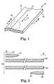
- FIG. 1 depicts a portion of one illustrative multilayer meltblown fibrous web 10.
- the web 10 can be provided in a discrete length in the machine direction, or it can be considered to have an endless length in the machine direction during manufacture.
- the web 10 preferably includes a centerline 11 and two separated edges 12 and 14 that are formed during manufacture of the flat web 10 from a tubular web as discussed below.
- the separated edges 12 and 14 are preferably generally parallel to the web centerline 11 and to each other.
- the machine direction as defined by the motion of a selected point on the forming surface of the collector used to manufacture the web 10, is also preferably parallel to the centerline 11 and the separated edges 12 and 14.
- the thickness or basis weight of the web is preferably generally constant between the separated edges. This feature of the meltblown fibrous webs of the invention is in direct contrast to the webs formed by conventional processes in which the thickness or basis weight generally tapers off near the web edges.
- edges 12 and 14 are depicted as being straight lines in FIG. 1, but edges 12 and 14 could also be provided in other shapes such as sinusoidal or other waveforms. In any event, however, the web edges 12 and 14 will generally extend in directions that are parallel to the web centerline 11.
- edges 12 and 14 can vary.
- the edges may be slit using techniques including, but are not limited to, knife slitting, laser slitting, water jet slitting, ultrasonic slitting, hot wire slitting, flame slitting, etc.
- the web edges 12 and 14 can be formed in a rotary die cutting process, or they can be formed by controlled tearing of the web in a predetermined pattern. For example, it may be helpful to perforate, crease, or otherwise modify the tubular web before tearing to assist in controlling the tear direction.
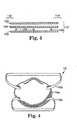
- FIG. 2 illustrates various layers in the multilayer meltblown fibrous web 10.
- the relative dimensions and features depicted in FIG. 2 are exaggerated for the purposes of illustration.
- the web 10 preferably includes a plurality of interconnected layers of meltblown fibers, with each layer being deposited sequentially as will be described in more detail below.
- the layers included in the web 10 are a first layer 20, intermediate layers 22 and 24, and a second layer 26. Both the first layer 20 and the second layer 26 include feathered edges 21 and 27, respectively.
- the feathered edges 21 and 27 are the result of the meltblown fiber deposition process in which the basis weight is gradually reduced to zero at the edges of the layer of meltblown fibers provided by the meltblown fiber source.
- the feathered edges would be located at the outer side edges of the formed web, where they typically would be trimmed from the web and discarded as waste material.
- the feathered edges 21 and 27 are incorporated into the multilayer meltblown fibrous web 10 in a manner that produces a web 10 having two separated edges 12 and 14, at least one feathered edge located between the two separated edges 12 and 14 and parallel to those edges 12 and 14, and at least one pair of interconnected layers of meltblown fibers.
- each layer is preferably interconnected by fiber entanglement to at least the immediately adjacent layer.
- the meltblown fibers of the first layer 20 are preferably entangled with the meltblown fibers of the intermediate layer 22, which are, in turn, entangled with the meltblown fibers of the intermediate layer 24, which are entangled with the meltblown fibers in the second layer 26.
- the layers that are not immediately adjacent to each other may also be interconnected depending on the layer thickness, the fibers being deposited, and the process used to deposit the fibers.
- the meltblown fibers in the first layer 20 could be entangled with the meltblown fibers in both intermediate layer 22 as well as intermediate layer 24 in some instances if, for example, each layer was thin enough to allow such entanglement to occur.
- a preferred mechanism by which the layers of the multilayer meltblown fibrous web 10 are interconnected is preferably by the same manner in which the individual layers are formed.
- the process involves directing a source of meltblown fibers towards at least one already-formed layer or layers of meltblown fibers.
- the meltblown fibers of the different layers 20, 22, 24 and 26 of the multilayer meltblown fibrous web 10 preferably become entangled by the same process used to entangle the individual fibers forming each layer together.
- no additional adhesive, resin, etc. or any processing, such as pin welding may be required to secure the various layers 20, 22, 24 and 26 together.
- additional agents or processing steps may sometimes be used to desirably assist in the interconnection of the layers of meltblown fibers together to form the finished web 10.
- a resin, adhesive or other agents may be introduced in each layer or between adjacent layers to assist layer interconnection.
- the cross-sectional view taken in FIG. 2 is taken in the direction of the section line 2-2 across the web 10 (along the edges 12 and 14 ) and, as a result, the direction of the cross-section seen in FIG. 2 is also generally in the machine direction.
- the cross-sectional view of the multilayer meltblown fibrous web 10 in FIG. 2 illustrates another feature of the present invention, namely, the spatial relationship of feathered edges 21 and 27 to the separated edges 12 and 14.
- the feathered edges 21 and 27 are parallel to the separated edges 12 and 14 of the meltblown fibrous web 10 (see also FIG. 1).
- tubular formed webs that are longitudinally slit to form a flat meltblown fibrous web.
- the feathered edges that are formed during manufacture of the tubular webs extend at an angle across the web, thereby forming a bias angle with respect to the centerline of the flat web. This is a result of slitting the tubular web longitudinally.
- the tubular multilayer meltblown fibrous web is slit helically and the resulting flat muitilayer meltblown fibrous web 10 incorporates feathered edges that extend parallel to the separated edges 12 and 14.
- meltblown fibrous webs 10 Another feature of the meltblown fibrous webs 10 is the multilayer construction of the finished web 10. Although only two intermediate layers 22 and 24 are depicted in FIG. 2, each of these intermediate layers 22, 24 could be themselves formed of a plurality of separate layers such that the multilayer meltblown fibrous web 10 could be formed of 3, 4, 5, 6, 7 or more sequentially-formed layers of meltblown fibers including first and second layers and at least one intermediate layer.
- the multilayer meltblown fibrous web 10 percentage variations in the density or basis weight as a result of the feathered edges 21 and 27 is significantly reduced.
- the multilayer meltblown fibrous web 10 preferably includes at least one intermediate layer between the first and second layers 20 and 26. More preferably, the multilayer meltblown fibrous web 10 includes about four or more intermediate layers between first and second layers 20 and 26. These preferences, however, vary based on the intended use of the multilayer meltblown fibrous web 10 and a variety of other factors such as desired total basis weight, minimum basis weight of each layer, etc.
- a portion of the multilayer meltblown fibrous web 10 can be die cut, stamped, or otherwise separated from the web 10 to provide a multilayer meltblown fibrous article 18.
- Such articles 18 can exhibit characteristics unique to multilayer meltblown fibrous articles 18 manufactured from a multilayer meltblown fibrous web 10. Among those characteristics is that the article 18 includes a plurality of layers as described above.
- the meltblown fibers in each of the layers typically exhibit a detectable machine direction indicative of the helical movement of the collector on which the web 10 was formed.
- the machine directions exhibited by the meltblown fibers in each of the layers in the multilayer meltblown fibrous article 18 typically are parallel to each other because the layers are formed on the same collector.
- the machine direction of the collector on which a meltblown fibrous web 10 is formed can be determined, in one method, based on the tensile strength of the web.
- the tensile strength of the web 10 is generally higher in the cross-web direction than in the downweb direction (corresponding to the centerline of the web as described above).
- any feathered edges in multilayer meltblown articles 18 will be oriented generally transverse to the axis of maximum tensile strength.
- the machine direction can also be determined based on the shapes of fiber ropes or bundles in the meltblown fiber layers.
- meltblown fibrous webs When meltblown fibrous webs are formed, it is normal for some fibers to stick together and form fiber bundles or ropes.
- the fiber bundles are normally laid down in the web in the shape of an arc with the apex of the arc pointing in the downweb direction. Examination of a meltblown fibrous web 10 or article 18 on, for example, a light table should reveal the orientation of the fiber bundles.
- the multilayer meltblown fibrous articles 18 may also include one or more of the feathered edges 21 and 27 incorporated into the web 10 as described above. Those feathered edges 21 and 27 would generally be visible as being parallel to the machine directions defined by the meltblown fibers in each of the layers making up the multilayer meltblown fibrous articles 18.
- FIG. 3 depicts a cross-sectional view of another multilayer meltblown fibrous web 110.
- the web 110 includes a first portion 120 of meltblown fibers and a second portion 122 of meltblown fibers.
- the first and second portions 120 and 122 each preferably include a feathered edge of meltblown fibers on the outermost layers in those portions of the multilayer meltblown fibrous web 110 as described above with respect to multilayer meltblown fibrous web 10.
- Those feathered edges preferably extend parallel to the separated edges 112 and 114 of the multilayer meltblown fibrous web 110 as also discussed above with respect to multilayer meltblown fibrous web 10.
- Each of the first and second portions 120 and 122 can include one or more sequentially applied layers of meltblown fibers.
- the intermediate portion 124 may also include one or more materials other than the meltblown fibers.
- the other materials could be in the nature of films, particulates, fibers, liquids, and combinations thereof.
- intermediate portion 124 may include activated carbon to assist in removing gaseous and/or vaporous contaminants (see, for example, U.S. Patent 3,971,373 to Braun).
- the intermediate portion 124 could include a membrane having desired properties such as limited permeability, etc.
- the intermediate portion 124 of multilayer meltblown fibrous web 110 could comprise or consist essentially of these other materials, or the intermediate portion 124 may include those additional materials/layers in addition to one or more meltblown fibers layers.
- the web 110 may also incorporate one or more elements such as a fiber or thread 128 that extends generally parallel to the separated edges 112 and 114 of the web 110.
- suitable elements 128 include monofilament lines, woven threads, straps, etc.
- the additional elements 128 may be provided to improve the strength of the web 110 or provide a line along which the web 110 can be torn, folded, etc.
- meltblown fibers in intermediate portion 124 and/or the elements 128 do not inherently interconnect to or bond with the meltblown fibers in the remainder of the multilayer meltblown fibrous web 110, it may be desirable to provide one or more agents or perform other process steps (such as welding) to assist in bonding the meltblown fibers to those materials.
- agents or perform other process steps such as welding
- the intermediate portion 124 of the multilayer meltblown fibrous web 110 may include at least some meltblown fibers to assist in capturing, bonding, or entangling the various materials other than meltblown fibers in the multilayer meltblown fibrous web 110.
- the inventive multilayer meltblown fibrous articles can be incorporated into a variety of different products in which the properties of the inventive articles can be exploited.
- One type of product into which the multilayer meltblown fibrous articles may be incorporated is a mask worn over a person's breathing passages to prevent contaminants from entering the wearer's respiratory tract and/or protect other persons or things from exposure to pathogens or other contaminants expelled by the wearer during respiration.
- the term "mask" means a device adapted to serve either of these purposes and includes respirators and filtering face masks.
- FIG. 4 depicts one embodiment of a mask 16 that includes a porous mask body 17 and retaining straps 19.
- the mask body 17 may include a multilayer meltblown fibrous article of this invention as a filter media for filtering particulates.
- the mask body typically includes a support structure such as a shaping layer that supports the filter media.
- a substantial portion of the mask body may be constructed of a material that is substantially impermeable to air (see, for example, U.S. Patent 5,062,421 to Burns et al. which describes an elastomeric rubber face piece or U.S. Patent Re 35,062 to Brostrom et al.).
- the inventive multilayer meltblown articles may be used as a particulate filter that is supported in the filter cartridges.
- Masks having the cup-shaped configuration shown in FIG. 4 are described in, for example, U.S. Patent No. 5,307,796 to Kronzer et al., U.S. Patent No. 4,807,619 to Dyrud et al. and U.S. Patent No. 4,536,440 to Berg.
- Masks of the invention may take on other configurations, such as flat masks, alternative cup-shaped masks, and masks that include filtration assemblies. See, for example, U.S. Patent Nos.
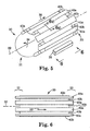
- FIG. 5 illustrates a portion of an apparatus for forming a multilayer meltblown fibrous webs.
- the portion of the apparatus illustrated in FIG. 5 includes a collector 30 that provides a generally cylindrical forming surface rotating about longitudinal axis 32 in the direction 34.
- the forming surface of the collector 30 also preferably moves longitudinally along the length of the longitudinal axis 32 in the direction of arrow 36.
- any selected point on the forming surface of collector 30 moves in a generally helical pattern about and along the longitudinal axis 32 from a first collector end 31 to a second collector end 33 .
- the illustrated apparatus also includes a source 38 of meltblown fibers that is directed at the forming surface of collector 30.
- the source 38 preferably extends along at least a portion of the longitudinal length of the collector 30 with one end of the source 38 being located near the first collector end 31 and the opposite end of the source 38 being located farther down the length of the collector 30 nearer to the second collector end 33.
- the preferred source 38 of meltblown fibers is a die, although essentially any other source of meltblown fibers is contemplated including, but not limited to, capillaries, spinerettes, etc.
- a preferred die directs meltblown fibers at the forming surface of the collector 30 along a generally straight line that is generally parallel to the longitudinal axis 32.
- the fibers can be directed onto the collector 30 using known techniques such as those described by Wente, Van A., "Superfine Thermoplastic Fibers," Industrial Engineering and Chemistry, Vol. 48, pp. 1342-1346 (1956), Report No. 4364 of the Naval Research Laboratories, published May 25, 1954, entitled Manufacture of Superfine Organic Fibers, by Wente, V.A.; Boone, C.D.; and Fluharty, E.L., and U.S. Patent No. 3,971,373 (Braun).
- the fibers are directed to the collector 30 by a high velocity gaseous stream (typically air) that attenuates the extruded material into fibers.
- One preferred collector 30 includes a forming surface that includes a plurality of rotating belts. The belts rotate such that the webs formed on the collector 30 move towards the second collector end 33.
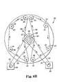
- FIG. 6 depicts one view of the collector 30 of FIG. 5 from the direction of line 6-6 in FIG. 5.
- the forming surface of the collector 30 includes a number of rotating belts 40a and 40b, all of which are rotating in the direction indicated by arrow 36 on the exterior of the collector 30.
- the belts 40a and 40b are rotating from a first collector end 31 to a second collector end 33.
- the forming surface of the collector 30 is composed of a series of alternating long belts 40a and short belts 40b to allow room for the power transfer components needed to transfer power to the drive rolls 41a and 41b supporting the ends of the long belts 40a and 40b, respectively.
- the belts 40a and 40b are depicted in an adjacent planar relationship, in other words, as if the cylinder has been unrolled, in order to better illustrate the power transfer components.
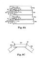
- each power input shaft 42 includes an outer drive sprocket 43 and is used to supply power to a first right angle gearbox 44 that includes an output shaft 45 supplying power to a drive roll 41a.
- the gearbox 44 also includes a second output shaft 46 supplying power to a timing belt 49 which transfers power to a transfer shaft 48.
- the transfer shaft 48 supplies power to a second right angle gearbox 50 that includes an output shaft 51 rotating the drive roll 41b that drives the short belt 40b.
- each of the power input shafts 42 drives one of the long belts 40a and an adjacent short belt 40b in the preferred collector apparatus 30.
- FIG. 6B The components used to transfer power to the power input shafts 42 and corresponding sprockets 43 are illustrated in FIG. 6B where an end view depicts the arrangement of the power input shafts 42 and drive sprockets 43 in the collector 30.
- the drive sprockets 43 are arranged about the longitudinal axis 32 of the collector 30 as seen in FIG. 6B.
- Belt drive sprocket 54 rotates about the longitudinal axis 32 and transfers power to the individual drive sprockets 43 via two chains 55 and 56 that rotate with the rotation of the belt drive sprocket 54.
- the belt drive sprocket 54 is preferably operatively attached to a drive sprocket 57 that is driven by a belt drive motor 58 using a separate chain 59.
- the drive sprocket 57 rotates, which, in turn, rotates the belt drive sprocket 54.
- the belt drive sprocket 54 drives the chains 55 and 56 which drive the power input shafts 42 via drive sprockets 43.
- the collection of belts 40a and 40b forming the cylindrical collector 30 rotate about the longitudinal axis 32 using the main drive sprocket 60, which receives power from main drive motor 62 via drive chain 61.
- the main drive sprocket 60 is operatively attached to the central shaft 52, the center of which is coextensive with the longitudinal axis 32.
- the belt drive sprocket 54 and drive sprocket 57 preferably mount to the central shaft 52, but rotate independently of it by the use of bearings located between the central shaft 52 and belt drive sprocket 54 /drive sprocket 57.
- the collector 30 includes separate drive systems for driving the belts 40a and 40b along the longitudinal axis 32 and simultaneously rotating the collector 30 about the longitudinal axis 32, the helix angle of the helix formed by the movement of a selected point on the forming surface of the collector 30 can be controlled.
- a single drive system could be used to power both the rotation of the belts 40a and 40b and the rotation of the collector 30 about the longitudinal axis 32, with changes between the relative rates of motion being made by gear ratio adjustments.
- the use of two separate drive systems does, however, provide the ability to quickly change that relationship without machine downtime.
- the belts 40a and 40b are preferably arranged with a relatively small gap between their adjacent edges such that, as meltblown fibers are directed at the forming surface of the collector 30 from the source 38, they are capable of forming a self-supporting layer of meltblown fibers.
- the maximum gap between the edges of adjacent belts 40a and 40b is preferably about 3 millimeters or less. Larger gaps may also be possible depending on the materials making up the meltblown fibers, the sizes of the meltblown fibers, the rate of deposition on the forming surface, the distance between the source of meltblown fibers and the forming surface, the temperature of the forming surface, etc.
- the belts are preferably nested within each other.
- FIG. 6C a partial enlarged cross-sectional view of the collector 30 taken along line 6C-6C in FIG. 5, the short belts 40b are located partially within the long belts 40a on the interior of the cylinder formed by the belts.
- the number of layers in the multilayer meltblown fibrous web is, in the apparatus including only one source 38 of meltblown fibers, a function of the relative rate of rotation of the collector 30 about axis 32, the rate of translational movement of the forming surface of the collector 30 in direction 36, and the distance along axis 32 over which the source 38 deposits meltblown fibers on the forming surface of the collector 30.
- the relative rate of rotation of the collector 30 about axis 32 as compared to the rate of translation 36 will preferably be such that any particular point on the surface of the collector 30 passes between source 38 and the forming surface of the collector 30 approximately six times during its helical movement about and along collector 30. Changing any one or more of the above-listed factors may have an impact on the number of layers of meltblown fibers provided in any multilayer meltblown fibrous web produced using the apparatus and methods of the present invention.
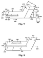
- FIG. 7 schematically illustrates one tubular multilayer meltblown fibrous web 280 and the cylindrical collector 230 onto which the web is formed.
- FIG. 7 shows a source 238 of meltblown fibers and a separator 270 in addition to the tubular web 280.
- the tubular web 280 is preferably formed on a collector 230 similar to collector 30 described above.
- the tubular web 280 is advanced along the longitudinal axis 232 in a direction 236 while simultaneously rotating about the axis 232 during formation on the collector.
- the simultaneous rotational and longitudinal movement of the collector 230 beneath the source 238 of meltblown fibers forms the feathered edges 221 and 227 as seen in FIG. 7 on the tubular meltblown fibrous web 280.
- first feathered edge 221 The helical nature of the first feathered edge 221, is illustrated in FIG. 7 where, above the source 238, the first feathered edge 221 extends from the outer-most or left-most portion of the source 238 while, after rotating about the collector, the same first feathered edge 221 is located at some distance across the length of the source 238 (along axis 232 ). Similarly, at the right-most or opposite end of the source 238 of meltblown fibers, the second feathered edge 227 associated with the flat multilayer meltblown fibrous web 210 is seen extending away from the source 238 towards the top of the tubular web 280.
- FIG. 7 also depicts a separator 270 that separates the tubular meltblown fibrous web 280 into a flat or planar web 210 having two separated edges 212 and 214.
- Angle ⁇ the angle at which the separator 270 operates on the tubular meltblown fibrous web 280 is substantially equal to the helix angle provided by the relationship between the rotation of collector 230 and resulting tubular web 280 about longitudinal axis 232 in combination with the translational motion 236 along the longitudinal axis 232. That helix angle is also the angle followed by the feathered edges 221 and 227 with axis 232.
- the separator 270 is illustrated as being near an end of the collector 230 in FIG. 7, the separator 270 may be located remote from the collector 230 in accordance with the present invention. Even when located remote from the collector 230, however, the separator 270 preferably separates the tubular multilayer meltblown fibrous web 280 along a direction generally parallel to the helix angle as discussed above.
- the flat multilayer meltblown fibrous web 210 will have a generally constant width between the separated edges 212 and 214.
- the multilayer meltblown fibrous web 210 also incorporates the feathered edges produced by the source 238 that would otherwise be trimmed from the web and discarded.
- the second feathered edge 227 is seen in the view of FIG. 7 and the first feathered edge is located on the opposite surface of the multilayer meltblown fibrous web 210.
- the flat multilayer meltblown fibrous web 210 can be either wound into a roll for use in other processes or the web 210 can be transferred directly into a manufacturing process in which the multilayer meltblown fibrous web 210 is used. Because the web 210 has two separated edges 212 and 214, there is no need to further trim the edges or deal with waste material as discussed above, thereby facilitating its use in such in-line manufacturing processes.
- the separator 270 could be provided in many different forms, and essentially any device that is capable of separating the web is contemplated by this invention.
- suitable separators 270 in the form of slitters include, but are not limited to: knives, lasers, water jets, ultrasonic horns, hot wires, flames, etc.
- Other contemplated separators may include rotary dies, lasers, water or fluid jet streams, and other devices or operations designed to separate a tubular multilayer meltblown fibrous web along a helical path.
- FIG. 7 also shows a vacuum source 290 connected to a manifold 292 located at one end of the collector 230.
- the manifold 292 is connected to the vacuum source 290 by line 294.
- Manifold 292 is preferably located at one end of the generally cylindrical forming surface of the collector 230.
- the web 280 preferably is formed on the collector 230 under slightly negative air pressure provided by the vacuum source 290 to assist in removing air and other gasses typically used in directing the meltblown fibers towards the forming surface of the collector 230.
- the forming surface preferably is permeable and, as a result, a negative pressure condition within the volume defined by the forming surface can be communicated through the forming surface.
- the flat multilayer meltblown fibrous web 210 produced on the collector 230 includes multiple layers of meltblown fibers in which the feathered edges 221 and 227 are incorporated into the web 210 between the separated edges 212 and 214.
- the exact location of the feathered edges 221 and 227 is, however, variable based on a number of factors.
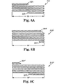
- FIGS. 8A-8C illustrate a variety of relationships possible within the flat multilayer meltblown fibrous webs 210 formed by operation of the collector apparatus 230.
- the width of each layer formed by the source of the meltblown fibers 238 (as measured along the longitudinal axis 232 ) should be at least as long as the distance over which a point on the forming surface travels in one complete revolution of the forming surface. That distance, in other words, the distance over which a point on the forming surface travels in one complete revolution of the forming surface, is sometimes referred to as the precession rate. If the width of each meltblown fiber layer is less than the precession rate, then gaps will be produced between the layers in the longitudinal direction.
- the width of the meltblown fiber layers will be assumed to be equal to the length of the meltblown fiber source 238.
- the actual width of the meltblown fiber layers on the forming surface can, however, vary from the length of the meltblown fiber source 238 by various manufacturing techniques involving airflow direction, etc.
- the spatial relationships between the feathered edges and the location of the feathered edges between the separated edges can vary based on the relationship between the length of the meltblown fiber source 238 along the longitudinal axis 232 as compared to the maximum width w of the flat multilayer meltblown fibrous web 210 between the separated edges, where the maximum width of the web 210 is determined by the precession rate of the collector.
- the maximum width of the web 210 is referred to with the understanding that the web 210 could be separated into two or more narrower webs, provided that the cumulative width of the narrower webs could not exceed the maximum width w which is a function of the precession rate under steady state operating conditions.
- the web 210 illustrated in FIG. 8A includes feathered edges 221 and 227 located directly above each other through the thickness of the web 210.
- the ratio of the longitudinal length l (see FIG. 7) of the source 238 (FIG. 7) to the width w of the web 210 is an integer relationship, in other words, l : w is about 1:1, 2:1, 3:1, etc.
- FIG. 8B illustrates that alignment of the feathered edges 221' and 227' can occur at any point across the width of the web 210' and is determined only by the original location of the separator 270 at which separation of the tubular web 280 is performed.
- the web 210' is also formed by a system in which the ratio of the longitudinal length of the meltblown fiber source to the width w ' of the web 210' is an integer relationship, in other words, 1:1, 2:1, 3:1, etc.
- the multilayer meltblown fibrous web 210" includes feathered edges 221" and 227" that are separated across the width of the web 210" .
- the width w" of the web is less than the longitudinal length of the meltblown fiber source.
- the feathered edges 221"/227" are not vertically aligned through the thickness of the web 210" because the ratio of the longitudinal length of the meltblown fiber source 238 (FIG. 7) to the width w" of the web 210" is not an integer relationship. In other words, that ratio is, for example, 1.6:1; 2.2:1, 3.1:1; etc.
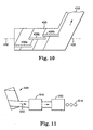
- meltblown fiber source 338 is used to deposit meltblown fibers on a rotating traversing collector 330.
- a secondary source 390 is also shown as depositing a different layer 392 on a portion of the forming surface of the collector 330. Because a portion of the tubular multilayer meltblown fibrous web 380 has already been deposited on the collector surface 330, the additional material or materials 392 provided by secondary source 390 are preferably located on top of at least one layer of meltblown fibers.
- an outer layer of meltblown fibers is deposited on top of the layer 392 as it passes underneath the source 338 of meltblown fibers at least one more time before reaching separator 370 where the tubular web 380 is separated along the helix angle to form a flat multilayer meltblown fibrous web 310 having separated edges 312 and 314.
- the material or materials provided by the secondary source 390 could be other than the meltblown fibers provided by the primary source 338.
- the secondary source could deposit activated carbon, materials needed to form a membrane within the tubular web 380, etc.
- the secondary source 390 could also provide only meltblown fibers to assist in providing multilayer meltblown fibrous webs having increased numbers of layers in collectors having shorter longitudinal lengths.
- Other variations that may be introduced into multilayer meltblown fibrous webs manufactured using one or more sources of meltblown fibers include variations in color of the webs, variations in fiber composition, variations in the fiber size and/or distribution throughout the thickness of the web, and others.
- FIG. 10 One approach to providing a graded density multilayer meltblown fibrous web 410 is illustrated in FIG. 10 in which a collector 430 is used in connection with three sources of meltblown fibers 438a, 438b and 438c (collectively referred to as sources 438 ). Each of the sources 438 is directed at a different portion of the collector 430 and forms a different layer of meltblown fibers on the tubular multilayer meltblown fibrous web 480. Although all the sources 438 could provide meltblown fibers having the same properties, it may be advantageous for each of the sources 438 to provide meltblown fibers having different properties. In that situation, the layers formed by each of the sources 438 could have different densities, different fiber compositions, or other properties.
- the apparatus 430 could be used to manufacture a graded density multilayer meltblown fibrous web 410 in which the feathered edge produced by each of the sources of meltblown fibers 438 is incorporated into the web 410 itself as discussed above.
- FIG. 11 One such system is illustrated in FIG. 11 in which the collector 530 is used in combination with converting stations 540 and 550.
- the web 510 produced by the collector 530 is guided directly into the first converting station 540 where one or more converting operations are performed followed by converting station 550 where one or more additional converting operations are performed to produce multilayer meltblown fiber articles 518 such as masks or other articles in an in-line process.
Landscapes
- Engineering & Computer Science (AREA)
- Textile Engineering (AREA)
- Chemical & Material Sciences (AREA)
- Chemical Kinetics & Catalysis (AREA)
- Nonwoven Fabrics (AREA)
- Filtering Materials (AREA)
- Absorbent Articles And Supports Therefor (AREA)
- Laminated Bodies (AREA)
- Spinning Methods And Devices For Manufacturing Artificial Fibers (AREA)
- Respiratory Apparatuses And Protective Means (AREA)
- Manufacture Of Alloys Or Alloy Compounds (AREA)
- Edible Seaweed (AREA)
Claims (16)
- Vorrichtung zur Herstellung eines Meltblown-Vliesstoffes, wobei diese Vorrichtung aufweist:(i) einen Kollektor (30, 230, 330, 430, 530) mit einer im Allgemeinen zylindrischen Formoberfläche, die um eine Längsachse (32, 232, 332) rotiert und die sich gleichzeitig parallel zur Längsachse (32) bewegt, so daß sich ein gegebener Punkt auf der Formoberfläche in einem Helixmuster um die und entlang der Längsachse (32) von einem ersten Ende (31) des Kollektors zu einem zweiten Ende (33) des Kollektors bewegt, wobei das Helixmuster einen Helixwinkel in bezug auf die Längsachse definiert,(ii) eine Quelle (38, 238, 338, 438), die die Meltblown-Fasern auf die Formoberfläche richtet; dadurch gekennzeichnet, daß die Vorrichtung weiterhin aufweist:(iii) einen Separator (270, 370), der den röhrenförmigen Meltblown-Vliesstoff, der auf der Formoberfläche gebildet wurde, in einer Richtung parallel zum Helixwinkel trennt, um den röhrenförmigen Meltblown-Vliesstoff in einen nicht-röhrenförmigen Meltblown-Vliesstoff umzuwandeln.
- Vorrichtung nach Anspruch 1, die weiterhin ein erstes Antriebssystem (54, 57, 58, 59) aufweist, das die Formoberfläche des Kollektors (30) um die Längsachse rotiert und ein zweites Antriebssystem (41a, 41b, 44, 45, 46, 48, 49, 50, 51), das die Formoberfläche entlang der Längsachse (32) bewegt, so daß die Rotationsgeschwindigkeit des Kollektors unabhängig von der Geschwindigkeit der Bewegung entlang der Längsachse geregelt werden kann, um den Helixwinkel zu variieren.
- Vorrichtung nach Anspruch 1 oder 2, wobei die Quelle (38) eine Formöffnung aufweist, die Mikrofasern extrudieren kann.
- Vorrichtung nach einem der Ansprüche 1 bis 3, die weiterhin eine zweite Quelle (390, 438a, 438b, 438c) aufweist, die das zweite Material auf die Umformfläche des Kollektors richtet.
- Verfahren zur Herstellung eines Meltblown-Vliesstoffes, wobei das Verfahren folgende Schritte aufweist:Bereitstellen eines Kollektors (30, 230, 330, 430, 530), der eine im Allgemeinen zylindrische Formoberfläche aufweist,Rotieren der Formoberfläche um eine Längsachse (32, 232, 332) und gleichzeitig longitudinales Bewegen der Formoberfläche in Richtung (236) der Längsachse (32, 232, 332), so daß sich ein gegebener Punkt auf der Formoberfläche in einem Helixmuster um die und entlang der Längsachse von einem Ende des Kollektors zum zweiten Ende des Kollektors bewegt, wobei das Helixmuster einen Helixwinkel in bezug auf die Längsachse definiert, wobei der gegebene Punkt auf der Formoberfläche um die Längsachse (232) mindestens zwei Mal in dem Zeitraum, der benötigt wird, um den gegebenen Punkt entlang der gesamten longitudinalen Länge der Formoberfläche zu bewegen, rotiert,Richten der Meltblown-Fasern auf die Formoberfläche während die Formoberfläche rotiert und sich in Längsrichtung bewegt, wobei ein röhrenförmiger Meltblown-Vliesstoff auf der Formoberfläche gebildet wird, undTrennen des röhrenförmigen Meltblown-Vliesstoffes entlang einer Richtung, die parallel zum Helixwinkel verläuft, um den röhrenförmigen Meltblown-Vliesstoff (280) in einen nicht-röhrenförmigen Meltblown-Vliesstoff (210) umzuwandeln.
- Verfahren nach Anspruch 5, wobei die Meltblown-Fasern Mikrofasern sind.
- Verfahren nach Anspruch 5 oder 6, das ferner das Einbringen einer persistenten elektrischen Ladung in die Mikrofasern aufweist, um einen elektrisch geladenen Stoff zu erzeugen.
- Verfahren zur Herstellung eines Filters, das das Einbringen des elektrisch geladenen Stoffes, der mittels des Verfahrens von Anspruch 7 hergestellt wurde, in eine Stützstruktur aufweist.
- Verfahren zur Herstellung einer Maske, das das Verfahren von Anspruch 8 aufweist, wobei es sich bei der Stützstruktur um eine becherförmige poröse Struktur handelt.
- Mehrlagiger Meltblown-Vliesstoff (10, 110, 210) mit:wobei die abgeschrägte Kante (21, 27; 221, 227) zwischen den getrennten Kanten (12, 14; 112, 114; 212, 214) liegt und wobei weiterhin die getrennten Kanten und die abgeschrägte Kante im Allgemeinen parallel zueinander sind.einer Vielzahl von miteinander verbundenen Meltblown-Faserlagen (20, 22, 24, 26; 120, 124, 122), wobei mindestens eine der Meltblown-Faserlagen (20, 26) eine abgeschrägte Kante (21, 27; 221, 227) aufweist undzwei getrennten Kanten (12, 14; 112, 114; 212, 214),
- Stoff nach Anspruch 10, wobei die Meltblown-Fasern (128) in jeder der Meltblown-Faserlagen (120, 122) eine Prozeßrichtung bestimmen und wobei weiterhin die Prozeßrichtungen von allen Meltblown-Faserlagen parallel zueinander verlaufen.
- Stoff nach Anspruch 10 oder 11, wobei alle Meltblown-Faserlagen eine abgeschrägte Kante besitzen und wobei weiterhin alle abgeschrägten Kanten parallel zu den getrennten Kanten des Stoffes verlaufen.
- Stoff nach einem der Ansprüche 10 bis 12, wobei die Vielzahl von Meltblown-Faserlagen mindestens eine Meltblownfaser-Zwischenlage aufweist, die zwischen zwei verschiedenen Meltblown-Faserlagen positioniert ist.
- Stoff nach einem der Ansprüche 10 bis 13, wobei der Stoff mindestens 3 Zwischenlagen aufweist, die zwischen den ersten und zweiten Lagen, die jeweils abgeschrägte Kanten enthalten, positioniert sind.
- Stoff nach einem der Ansprüche 10 bis 14, wobei die Faserschichten elektrisch geladene Mikrofasern enthalten.
- Stoff nach Anspruch 15, wobei dieser Bestandteil einer Maske (16) ist, die so ausgelegt ist, daß sie mindestens über Nase und Mund eines Trägers paßt und die ein Filterelement enthält, das so angeordnet ist, daß die Luft, die eingeatmet werden soll, das Filterelement, welches den Stoff aufweist, passiert, bevor sie eingeatmet wird.
Applications Claiming Priority (3)
| Application Number | Priority Date | Filing Date | Title |
|---|---|---|---|
| US09/181,205 US6139308A (en) | 1998-10-28 | 1998-10-28 | Uniform meltblown fibrous web and methods and apparatus for manufacturing |
| US181205 | 1998-10-28 | ||
| PCT/US1999/004104 WO2000024954A1 (en) | 1998-10-28 | 1999-02-25 | Uniform meltblown fibrous web and methods and apparatus for manufacturing |
Publications (2)
| Publication Number | Publication Date |
|---|---|
| EP1127183A1 EP1127183A1 (de) | 2001-08-29 |
| EP1127183B1 true EP1127183B1 (de) | 2003-08-20 |
Family
ID=22663326
Family Applications (1)
| Application Number | Title | Priority Date | Filing Date |
|---|---|---|---|
| EP99910995A Expired - Lifetime EP1127183B1 (de) | 1998-10-28 | 1999-02-25 | Gleichmässiger meltblown-vliesstoff, zugehörige vorrichtung und herstellungsverfahren |
Country Status (17)
| Country | Link |
|---|---|
| US (2) | US6139308A (de) |
| EP (1) | EP1127183B1 (de) |
| JP (1) | JP2002528655A (de) |
| KR (1) | KR100571461B1 (de) |
| CN (1) | CN1156622C (de) |
| AT (1) | ATE247731T1 (de) |
| AU (1) | AU758638B2 (de) |
| BR (1) | BR9914915A (de) |
| CA (1) | CA2346795A1 (de) |
| DE (1) | DE69910603T2 (de) |
| HK (1) | HK1040536A1 (de) |
| NO (1) | NO20012037L (de) |
| NZ (1) | NZ511273A (de) |
| PL (1) | PL196251B1 (de) |
| RU (1) | RU2215075C2 (de) |
| TW (1) | TW442587B (de) |
| WO (1) | WO2000024954A1 (de) |
Families Citing this family (43)
| Publication number | Priority date | Publication date | Assignee | Title |
|---|---|---|---|---|
| US6139308A (en) | 1998-10-28 | 2000-10-31 | 3M Innovative Properties Company | Uniform meltblown fibrous web and methods and apparatus for manufacturing |
| ATE546182T1 (de) * | 2003-12-08 | 2012-03-15 | Fisher & Paykel Healthcare Ltd | Gerät zur unterstützung der atmung |
| US7320722B2 (en) * | 2004-10-29 | 2008-01-22 | 3M Innovative Properties Company | Respiratory protection device that has rapid threaded clean air source attachment |
| CZ20041086A3 (cs) * | 2004-11-01 | 2006-06-14 | Bauer@Václav | Obvazový materiál s aktivními uhlíkovými vlákny |
| US7419526B2 (en) * | 2005-03-03 | 2008-09-02 | 3M Innovative Properties Company | Conformal filter cartridges and methods |
| DE102005059214B4 (de) * | 2005-12-12 | 2007-10-25 | Eurofilters N.V. | Filterbeutel für einen Staubsauger |
| US20080233850A1 (en) * | 2007-03-20 | 2008-09-25 | 3M Innovative Properties Company | Abrasive article and method of making and using the same |
| US7628829B2 (en) * | 2007-03-20 | 2009-12-08 | 3M Innovative Properties Company | Abrasive article and method of making and using the same |
| US20080271739A1 (en) | 2007-05-03 | 2008-11-06 | 3M Innovative Properties Company | Maintenance-free respirator that has concave portions on opposing sides of mask top section |
| US9770611B2 (en) | 2007-05-03 | 2017-09-26 | 3M Innovative Properties Company | Maintenance-free anti-fog respirator |
| US7926204B2 (en) * | 2007-10-11 | 2011-04-19 | Nike, Inc. | Article of footwear with tubular sole assembly and method of manufacture |
| WO2009085679A1 (en) * | 2007-12-28 | 2009-07-09 | 3M Innovative Properties Company | Composite nonwoven fibrous webs and methods of making and using the same |
| WO2009088648A1 (en) * | 2007-12-31 | 2009-07-16 | 3M Innovative Properties Company | Composite non-woven fibrous webs having continuous particulate phase and methods of making and using the same |
| JP5221676B2 (ja) * | 2007-12-31 | 2013-06-26 | スリーエム イノベイティブ プロパティズ カンパニー | 流体濾過物品とその作製方法及び使用方法 |
| KR100986351B1 (ko) * | 2008-04-29 | 2010-10-08 | 현대자동차주식회사 | 자동차 파트 자동 피더기 |
| US8069587B2 (en) * | 2008-11-20 | 2011-12-06 | 3M Innovative Properties Company | Molded insulated shoe footbed and method of making an insulated footbed |
| US11083916B2 (en) | 2008-12-18 | 2021-08-10 | 3M Innovative Properties Company | Flat fold respirator having flanges disposed on the mask body |
| US8640704B2 (en) | 2009-09-18 | 2014-02-04 | 3M Innovative Properties Company | Flat-fold filtering face-piece respirator having structural weld pattern |
| US8881729B2 (en) | 2009-09-18 | 2014-11-11 | 3M Innovative Properties Company | Horizontal flat-fold filtering face-piece respirator having indicia of symmetry |
| US8528560B2 (en) | 2009-10-23 | 2013-09-10 | 3M Innovative Properties Company | Filtering face-piece respirator having parallel line weld pattern in mask body |
| CN102085437A (zh) * | 2009-12-04 | 2011-06-08 | 东丽纤维研究所(中国)有限公司 | 一种空气过滤用滤材及其用途 |
| CN102711920A (zh) | 2009-12-30 | 2012-10-03 | 3M创新有限公司 | 在面罩主体中具有拉胀网片的过滤式面具呼吸器 |
| US20120017911A1 (en) | 2010-07-26 | 2012-01-26 | 3M Innovative Properties Company | Filtering face-piece respirator having foam shaping layer |
| US9700743B2 (en) | 2012-07-31 | 2017-07-11 | 3M Innovative Properties Company | Respiratory assembly including latching mechanism |
| WO2013019764A2 (en) | 2011-08-01 | 2013-02-07 | 3M Innovative Properties Company | Respiratory assembly including latching mechanism |
| US11116998B2 (en) | 2012-12-27 | 2021-09-14 | 3M Innovative Properties Company | Filtering face-piece respirator having folded flange |
| US10182603B2 (en) | 2012-12-27 | 2019-01-22 | 3M Innovative Properties Company | Filtering face-piece respirator having strap-activated folded flange |
| US9510626B2 (en) | 2013-02-01 | 2016-12-06 | 3M Innovative Properties Company | Sleeve-fit respirator cartridge |
| EP3110275B1 (de) | 2014-02-27 | 2019-01-09 | 3M Innovative Properties Company | Atemgerät mit elastischen bändern mit lochmusterstruktur |
| US10040621B2 (en) | 2014-03-20 | 2018-08-07 | 3M Innovative Properties Company | Filtering face-piece respirator dispenser |
| MX2017002082A (es) | 2014-08-18 | 2017-07-10 | 3M Innovative Properties Co | Respirador que incluye malla metalica polimerica y metodo para su formacion. |
| CA2966012A1 (en) | 2014-10-31 | 2016-05-06 | 3M Innovative Properties Company | Respirator having corrugated filtering structure |
| GB201508114D0 (en) | 2015-05-12 | 2015-06-24 | 3M Innovative Properties Co | Respirator tab |
| RU2015141569A (ru) | 2015-09-30 | 2017-04-05 | 3М Инновейтив Пропертиз Компани | Складной респиратор с лицевой маской и клапаном выдоха |
| RU2702244C1 (ru) | 2015-11-11 | 2019-10-07 | 3М Инновейтив Пропертиз Компани | Сохраняющий форму респиратор, складываемый до плоского состояния |
| EP3515662B1 (de) | 2016-09-26 | 2024-01-10 | 3M Innovative Properties Company | Vliesschleifartikel mit elektrostatisch ausgerichteten schleifpartikeln und verfahren zur herstellung davon |
| JP2019535374A (ja) | 2016-10-28 | 2019-12-12 | スリーエム イノベイティブ プロパティズ カンパニー | 補強要素を含むレスピレータ |
| RU2671037C2 (ru) | 2017-03-17 | 2018-10-29 | 3М Инновейтив Пропертиз Компани | Складной респиратор с лицевой маской типа ffp3 |
| US11813581B2 (en) | 2017-07-14 | 2023-11-14 | 3M Innovative Properties Company | Method and adapter for conveying plural liquid streams |
| US11447893B2 (en) | 2017-11-22 | 2022-09-20 | Extrusion Group, LLC | Meltblown die tip assembly and method |
| DE102019203986B4 (de) * | 2019-03-22 | 2022-07-07 | Adidas Ag | Vliesstoffartikel |
| DE102020107746A1 (de) | 2020-03-20 | 2021-09-23 | Solvamed Gmbh | Verbesserte Atemschutzmaske |
| CN115485051B (zh) * | 2020-04-20 | 2024-08-16 | 米歇尔·塞库尔斯 | 作为/用于耐用耐洗高性能过滤介质的多层织物及其组装方法 |
Family Cites Families (48)
| Publication number | Priority date | Publication date | Assignee | Title |
|---|---|---|---|---|
| US3870A (en) * | 1844-12-31 | Improvement in seed-planters | ||
| US34328A (en) * | 1862-02-04 | Improved budding-knife | ||
| US3909A (en) * | 1845-02-12 | Boot-crimp | ||
| US28102A (en) * | 1860-05-01 | Stove-gkrate | ||
| US4301A (en) * | 1845-12-11 | Ebenezbr barrows | ||
| US3613678A (en) * | 1970-02-24 | 1971-10-19 | Minnesota Mining & Mfg | Filtration mask |
| US3784427A (en) * | 1970-06-03 | 1974-01-08 | Burlington Industries Inc | Method of making and treating bias cut fabric |
| US3870478A (en) * | 1970-07-17 | 1975-03-11 | Gates Rubber Co | Method of preparing a bias fabric |
| US3686050A (en) * | 1970-07-17 | 1972-08-22 | Kimberly Clark Co | Method and apparatus for making seamless cross-bias reinforced tissue-fiber laminates |
| US3758373A (en) * | 1971-04-12 | 1973-09-11 | Celanese Corp | Spray-spun continuous tubular structure |
| JPS526189B2 (de) * | 1972-08-23 | 1977-02-19 | ||
| US4032688A (en) * | 1973-08-31 | 1977-06-28 | Pall Corporation | Seamless tubular nonwoven webs and filters thereof |
| GB1459658A (en) * | 1973-12-24 | 1976-12-22 | Moeller & Neumann Gmbh | Wire rod coiler for large bundles or coils |
| US3909174A (en) * | 1973-12-26 | 1975-09-30 | Beloit Corp | Continuous tube forming by melt blowing technique |
| US3905734A (en) * | 1973-12-26 | 1975-09-16 | Beloit Corp | Continuous tube forming by melt blowing technique |
| US3971373A (en) * | 1974-01-21 | 1976-07-27 | Minnesota Mining And Manufacturing Company | Particle-loaded microfiber sheet product and respirators made therefrom |
| US4215682A (en) * | 1978-02-06 | 1980-08-05 | Minnesota Mining And Manufacturing Company | Melt-blown fibrous electrets |
| US4301203A (en) * | 1978-07-27 | 1981-11-17 | Pnc Company | Manufacturing a thermoplastic non-woven web comprising coherently interconnected filaments |
| US4298649A (en) * | 1980-01-07 | 1981-11-03 | Kimberly-Clark Corporation | Nonwoven disposable wiper |
| US4419993A (en) * | 1981-12-10 | 1983-12-13 | Minnesota Mining & Manufacturing Company | Anti-fogging surgical mask |
| US4729371A (en) * | 1983-10-11 | 1988-03-08 | Minnesota Mining And Manufacturing Company | Respirator comprised of blown bicomponent fibers |
| US4795668A (en) * | 1983-10-11 | 1989-01-03 | Minnesota Mining And Manufacturing Company | Bicomponent fibers and webs made therefrom |
| US4547420A (en) * | 1983-10-11 | 1985-10-15 | Minnesota Mining And Manufacturing Company | Bicomponent fibers and webs made therefrom |
| JPS60168511A (ja) * | 1984-02-10 | 1985-09-02 | Japan Vilene Co Ltd | エレクトレツトフイルタの製造方法 |
| US4536440A (en) * | 1984-03-27 | 1985-08-20 | Minnesota Mining And Manufacturing Company | Molded fibrous filtration products |
| US4807619A (en) * | 1986-04-07 | 1989-02-28 | Minnesota Mining And Manufacturing Company | Resilient shape-retaining fibrous filtration face mask |
| DE3645194C2 (de) | 1986-04-14 | 1995-01-05 | Windmoeller & Hoelscher | Wendelschneideinrichtung |
| GB8612070D0 (en) * | 1986-05-19 | 1986-06-25 | Brown R C | Blended-fibre filter material |
| US5099026A (en) * | 1986-09-12 | 1992-03-24 | Crater Davis H | Fluorochemical oxazolidinones |
| US5025052A (en) * | 1986-09-12 | 1991-06-18 | Minnesota Mining And Manufacturing Company | Fluorochemical oxazolidinones |
| US4827924A (en) * | 1987-03-02 | 1989-05-09 | Minnesota Mining And Manufacturing Company | High efficiency respirator |
| US4883547A (en) * | 1987-03-02 | 1989-11-28 | Minnesota Mining And Manufacturing Company | Method of forming a high efficiency respirator |
| US5062421A (en) * | 1987-11-16 | 1991-11-05 | Minnesota Mining And Manufacturing Company | Respiratory mask having a soft, compliant facepiece and a thin, rigid insert and method of making |
| US5141699A (en) * | 1987-12-21 | 1992-08-25 | Minnesota Mining And Manufacturing Company | Process for making oriented melt-blown microfibers |
| US4988560A (en) * | 1987-12-21 | 1991-01-29 | Minnesota Mining And Manufacturing Company | Oriented melt-blown fibers, processes for making such fibers, and webs made from such fibers |
| JP2672329B2 (ja) * | 1988-05-13 | 1997-11-05 | 東レ株式会社 | エレクトレット材料 |
| GB8815083D0 (en) * | 1988-06-24 | 1988-08-03 | Rasmussen O B | Method & apparatus for helical cutting of lay-flat flexible tubular sheet of polymer material |
| US5307796A (en) * | 1990-12-20 | 1994-05-03 | Minnesota Mining And Manufacturing Company | Methods of forming fibrous filtration face masks |
| TW206266B (de) * | 1991-06-12 | 1993-05-21 | Toray Industries | |
| US5503782A (en) * | 1993-01-28 | 1996-04-02 | Minnesota Mining And Manufacturing Company | Method of making sorbent articles |
| AU669420B2 (en) * | 1993-03-26 | 1996-06-06 | Minnesota Mining And Manufacturing Company | Oily mist resistant electret filter media |
| US5437910A (en) * | 1993-07-21 | 1995-08-01 | Steinbeis Gessner Gmbh | Multi-ply filter lasminate/composite for manufacturing vacuum cleaner filter bags |
| EP0714463B1 (de) * | 1993-08-17 | 1999-03-10 | Minnesota Mining And Manufacturing Company | Verfahren zur aufladung von elektretfiltermedien |
| US5582907A (en) * | 1994-07-28 | 1996-12-10 | Pall Corporation | Melt-blown fibrous web |
| EP0772484B1 (de) * | 1994-07-28 | 2008-02-27 | Pall Corporation | Faserstoffbahn und verfahren zur dessen herstellung |
| US5706804A (en) * | 1996-10-01 | 1998-01-13 | Minnesota Mining And Manufacturing Company | Liquid resistant face mask having surface energy reducing agent on an intermediate layer therein |
| US5900305A (en) * | 1997-01-24 | 1999-05-04 | Chapman; Rick L. | Laminated high efficiency filter |
| US6139308A (en) | 1998-10-28 | 2000-10-31 | 3M Innovative Properties Company | Uniform meltblown fibrous web and methods and apparatus for manufacturing |
-
1998
- 1998-10-28 US US09/181,205 patent/US6139308A/en not_active Expired - Lifetime
-
1999
- 1999-02-25 JP JP2000578504A patent/JP2002528655A/ja not_active Withdrawn
- 1999-02-25 CN CNB998126942A patent/CN1156622C/zh not_active Expired - Fee Related
- 1999-02-25 AT AT99910995T patent/ATE247731T1/de not_active IP Right Cessation
- 1999-02-25 EP EP99910995A patent/EP1127183B1/de not_active Expired - Lifetime
- 1999-02-25 DE DE69910603T patent/DE69910603T2/de not_active Expired - Fee Related
- 1999-02-25 AU AU29743/99A patent/AU758638B2/en not_active Ceased
- 1999-02-25 WO PCT/US1999/004104 patent/WO2000024954A1/en not_active Ceased
- 1999-02-25 NZ NZ511273A patent/NZ511273A/en unknown
- 1999-02-25 CA CA002346795A patent/CA2346795A1/en not_active Abandoned
- 1999-02-25 RU RU2001111032/12A patent/RU2215075C2/ru not_active IP Right Cessation
- 1999-02-25 KR KR1020017005265A patent/KR100571461B1/ko not_active Expired - Fee Related
- 1999-02-25 BR BR9914915-0A patent/BR9914915A/pt not_active Application Discontinuation
- 1999-02-25 HK HK02100186.2A patent/HK1040536A1/zh unknown
- 1999-02-25 PL PL348662A patent/PL196251B1/pl unknown
- 1999-10-08 TW TW088117432A patent/TW442587B/zh not_active IP Right Cessation
-
2000
- 2000-09-27 US US09/670,642 patent/US6492286B1/en not_active Expired - Fee Related
-
2001
- 2001-04-25 NO NO20012037A patent/NO20012037L/no not_active Application Discontinuation
Also Published As
| Publication number | Publication date |
|---|---|
| JP2002528655A (ja) | 2002-09-03 |
| KR100571461B1 (ko) | 2006-04-17 |
| US6139308A (en) | 2000-10-31 |
| ATE247731T1 (de) | 2003-09-15 |
| NO20012037L (no) | 2001-06-28 |
| HK1040536A1 (zh) | 2002-06-14 |
| CN1156622C (zh) | 2004-07-07 |
| AU2974399A (en) | 2000-05-15 |
| DE69910603D1 (de) | 2003-09-25 |
| NO20012037D0 (no) | 2001-04-25 |
| WO2000024954A9 (en) | 2001-11-01 |
| WO2000024954A1 (en) | 2000-05-04 |
| US6492286B1 (en) | 2002-12-10 |
| AU758638B2 (en) | 2003-03-27 |
| BR9914915A (pt) | 2004-12-07 |
| RU2215075C2 (ru) | 2003-10-27 |
| TW442587B (en) | 2001-06-23 |
| EP1127183A1 (de) | 2001-08-29 |
| CN1342229A (zh) | 2002-03-27 |
| DE69910603T2 (de) | 2004-06-24 |
| PL196251B1 (pl) | 2007-12-31 |
| PL348662A1 (en) | 2002-06-03 |
| CA2346795A1 (en) | 2000-05-04 |
| KR20010083924A (ko) | 2001-09-03 |
| NZ511273A (en) | 2003-11-28 |
Similar Documents
| Publication | Publication Date | Title |
|---|---|---|
| EP1127183B1 (de) | Gleichmässiger meltblown-vliesstoff, zugehörige vorrichtung und herstellungsverfahren | |
| US4375446A (en) | Process for the production of a nonwoven fabric | |
| KR100221708B1 (ko) | 다층 팽창 미세 섬유 웨브로 제조된 신규물질 및 그 특성 | |
| DE69321530T2 (de) | Gewellte Vliesstoffe aus polymerer Mikrofaser | |
| KR101471230B1 (ko) | 스테이플 섬유를 갖는 멜트블로운 섬유 웨브를 포함하는 성형된 호흡기 | |
| EP0868553B1 (de) | Hochwirksamer vliesstoff für atemschutzmaske | |
| US4229394A (en) | Multi-layer products | |
| KR101453591B1 (ko) | 스테이플 섬유를 갖는 멜트블로운 섬유 웨브 | |
| EP0051616B1 (de) | Chirurgische wegwerf-gesichtsmaske und verfahren zu ihrer herstellung | |
| US20020013112A1 (en) | Multi-drum manufacturing system for nonwoven materials | |
| SU578846A3 (ru) | Способ изготовлени сетки | |
| WO2001098574A2 (en) | Multi-drum manufacturing system for nonwoven materials | |
| WO2000029656A1 (en) | Method and apparatus for manufacturing non-woven articles | |
| WO2000029656A9 (en) | Method and apparatus for manufacturing non-woven articles | |
| JP2006507891A (ja) | 複合吸収材製品、その製造方法および装置 | |
| MXPA01004279A (de) | ||
| EP1437167A1 (de) | Filtermedium und Verfahren zu dessen Herstellung | |
| JP2023013341A (ja) | 不織布、マスクおよび不織布製造装置 | |
| JP2022029744A (ja) | 不織布、不織布製造方法および不織布製造装置 |
Legal Events
| Date | Code | Title | Description |
|---|---|---|---|
| PUAI | Public reference made under article 153(3) epc to a published international application that has entered the european phase |
Free format text: ORIGINAL CODE: 0009012 |
|
| 17P | Request for examination filed |
Effective date: 20010517 |
|
| AK | Designated contracting states |
Kind code of ref document: A1 Designated state(s): AT BE CH DE DK ES FI FR GB IT LI NL SE |
|
| 17Q | First examination report despatched |
Effective date: 20011114 |
|
| GRAH | Despatch of communication of intention to grant a patent |
Free format text: ORIGINAL CODE: EPIDOS IGRA |
|
| GRAH | Despatch of communication of intention to grant a patent |
Free format text: ORIGINAL CODE: EPIDOS IGRA |
|
| GRAA | (expected) grant |
Free format text: ORIGINAL CODE: 0009210 |
|
| AK | Designated contracting states |
Designated state(s): AT BE CH DE DK ES FI FR GB IT LI NL SE |
|
| PG25 | Lapsed in a contracting state [announced via postgrant information from national office to epo] |
Ref country code: NL Free format text: LAPSE BECAUSE OF FAILURE TO SUBMIT A TRANSLATION OF THE DESCRIPTION OR TO PAY THE FEE WITHIN THE PRESCRIBED TIME-LIMIT Effective date: 20030820 Ref country code: LI Free format text: LAPSE BECAUSE OF FAILURE TO SUBMIT A TRANSLATION OF THE DESCRIPTION OR TO PAY THE FEE WITHIN THE PRESCRIBED TIME-LIMIT Effective date: 20030820 Ref country code: FR Free format text: LAPSE BECAUSE OF FAILURE TO SUBMIT A TRANSLATION OF THE DESCRIPTION OR TO PAY THE FEE WITHIN THE PRESCRIBED TIME-LIMIT Effective date: 20030820 Ref country code: FI Free format text: LAPSE BECAUSE OF FAILURE TO SUBMIT A TRANSLATION OF THE DESCRIPTION OR TO PAY THE FEE WITHIN THE PRESCRIBED TIME-LIMIT Effective date: 20030820 Ref country code: CH Free format text: LAPSE BECAUSE OF FAILURE TO SUBMIT A TRANSLATION OF THE DESCRIPTION OR TO PAY THE FEE WITHIN THE PRESCRIBED TIME-LIMIT Effective date: 20030820 Ref country code: BE Free format text: LAPSE BECAUSE OF FAILURE TO SUBMIT A TRANSLATION OF THE DESCRIPTION OR TO PAY THE FEE WITHIN THE PRESCRIBED TIME-LIMIT Effective date: 20030820 Ref country code: AT Free format text: LAPSE BECAUSE OF FAILURE TO SUBMIT A TRANSLATION OF THE DESCRIPTION OR TO PAY THE FEE WITHIN THE PRESCRIBED TIME-LIMIT Effective date: 20030820 |
|
| REG | Reference to a national code |
Ref country code: GB Ref legal event code: FG4D |
|
| REG | Reference to a national code |
Ref country code: CH Ref legal event code: EP |
|
| REF | Corresponds to: |
Ref document number: 69910603 Country of ref document: DE Date of ref document: 20030925 Kind code of ref document: P |
|
| PG25 | Lapsed in a contracting state [announced via postgrant information from national office to epo] |
Ref country code: SE Free format text: LAPSE BECAUSE OF FAILURE TO SUBMIT A TRANSLATION OF THE DESCRIPTION OR TO PAY THE FEE WITHIN THE PRESCRIBED TIME-LIMIT Effective date: 20031120 Ref country code: DK Free format text: LAPSE BECAUSE OF FAILURE TO SUBMIT A TRANSLATION OF THE DESCRIPTION OR TO PAY THE FEE WITHIN THE PRESCRIBED TIME-LIMIT Effective date: 20031120 |
|
| PG25 | Lapsed in a contracting state [announced via postgrant information from national office to epo] |
Ref country code: ES Free format text: LAPSE BECAUSE OF FAILURE TO SUBMIT A TRANSLATION OF THE DESCRIPTION OR TO PAY THE FEE WITHIN THE PRESCRIBED TIME-LIMIT Effective date: 20031201 |
|
| NLV1 | Nl: lapsed or annulled due to failure to fulfill the requirements of art. 29p and 29m of the patents act | ||
| REG | Reference to a national code |
Ref country code: CH Ref legal event code: PL |
|
| PLBE | No opposition filed within time limit |
Free format text: ORIGINAL CODE: 0009261 |
|
| STAA | Information on the status of an ep patent application or granted ep patent |
Free format text: STATUS: NO OPPOSITION FILED WITHIN TIME LIMIT |
|
| 26N | No opposition filed |
Effective date: 20040524 |
|
| EN | Fr: translation not filed | ||
| PGFP | Annual fee paid to national office [announced via postgrant information from national office to epo] |
Ref country code: IT Payment date: 20070519 Year of fee payment: 9 |
|
| PGFP | Annual fee paid to national office [announced via postgrant information from national office to epo] |
Ref country code: GB Payment date: 20080227 Year of fee payment: 10 |
|
| PGFP | Annual fee paid to national office [announced via postgrant information from national office to epo] |
Ref country code: DE Payment date: 20080331 Year of fee payment: 10 |
|
| REG | Reference to a national code |
Ref country code: HK Ref legal event code: WD Ref document number: 1040536 Country of ref document: HK |
|
| PG25 | Lapsed in a contracting state [announced via postgrant information from national office to epo] |
Ref country code: IT Free format text: LAPSE BECAUSE OF NON-PAYMENT OF DUE FEES Effective date: 20080225 |
|
| GBPC | Gb: european patent ceased through non-payment of renewal fee |
Effective date: 20090225 |
|
| PG25 | Lapsed in a contracting state [announced via postgrant information from national office to epo] |
Ref country code: DE Free format text: LAPSE BECAUSE OF NON-PAYMENT OF DUE FEES Effective date: 20090901 |
|
| PG25 | Lapsed in a contracting state [announced via postgrant information from national office to epo] |
Ref country code: GB Free format text: LAPSE BECAUSE OF NON-PAYMENT OF DUE FEES Effective date: 20090225 |