EP1126482A2 - Multi-directional slide switch - Google Patents
Multi-directional slide switch Download PDFInfo
- Publication number
- EP1126482A2 EP1126482A2 EP01103002A EP01103002A EP1126482A2 EP 1126482 A2 EP1126482 A2 EP 1126482A2 EP 01103002 A EP01103002 A EP 01103002A EP 01103002 A EP01103002 A EP 01103002A EP 1126482 A2 EP1126482 A2 EP 1126482A2
- Authority
- EP
- European Patent Office
- Prior art keywords
- slide member
- slide
- operating knob
- directional
- wafer
- Prior art date
- Legal status (The legal status is an assumption and is not a legal conclusion. Google has not performed a legal analysis and makes no representation as to the accuracy of the status listed.)
- Granted
Links
Images


Classifications
-
- H—ELECTRICITY
- H01—ELECTRIC ELEMENTS
- H01H—ELECTRIC SWITCHES; RELAYS; SELECTORS; EMERGENCY PROTECTIVE DEVICES
- H01H25/00—Switches with compound movement of handle or other operating part
- H01H25/002—Switches with compound movement of handle or other operating part having an operating member rectilinearly slidable in different directions
- H01H2025/004—Switches with compound movement of handle or other operating part having an operating member rectilinearly slidable in different directions the operating member being depressable perpendicular to the other directions
Definitions
- This invention relates to a multi-directional slide switch used, for example, for scroll operating the content of the screen display for various kinds of electronic equipment, and more particularly, a multi-slide switch that is preferable for improving its operability.
- the slide switch was used for performing a scroll operation of the content displayed in the screen of various kinds of electronic equipment, for example.
- the slide switch In the case that only one-directional operation was satisfactory for the scroll operation, its accommodation for it was possible by applying one directional slide switch where an operator could operate one directional switching operation.
- the present invention is comprised of a case having a fixed contact member and a first slide member and a second slide member arranged in the case and slidably guided in crossing two axes direction, respectively, and is characterized in that the first slide member is provided with an operating knob and a movable contact member, the operating knob is projected outside the case, the operating knob is operated to a predetermined position of two-axis coordinates, thereby each of the first slide member and the second slid member is slid in the two-axis direction, the movable contact member is brought into contact with the fixed contact member, and a multi-directional switching operation of the operating knob is carried out.
- the present invention is characterized in that the movable contact member is fitted to and fixed to a rear surface opposite to the operating knob of the first slide member, the second slide member is provided with a through hole through which the operating knob can freely fit in a sliding direction of the first slide member, and the operating knob inserted into the through hole is projected outside the case.
- the present invention is characterized in that the case is comprised of a wafer having the fixed contact member at its inner bottom surface and a cover mounted so as to cover the wafer, a rear surface of the second slide member is provided with a first guide section, the first slide member is provided with a first engaging section slidably engaged with the first guide section, in addition, the cover is provided with an insertion hole through which the operating knob is projected outwardly and its rear surface is provided with a second guide section, further, the second slide member is provided with a second engaging section slidably engaged with the second guide section, each of the first slide member and second slide member is slidably guided in the two-axis direction in respect to the cover.
- each of the second slide member and the rear surface of the cover is provided with a resilient member for use in returning each of the first slide member and second slide member to a predetermined initial position with a resilient force, respectively.
- the present invention is characterized in that the resilient member is a helical torsion spring, the helical torsion springs are arranged at both sides in a sliding direction of each of the first engaging section and a second engaging section, respectively, the first and second engaging sections are biased by the end sections of the helical torsion springs against sliding motions of the first engaging section and the second engaging section and returned back to the their initial positions.
- the resilient member is a helical torsion spring
- the helical torsion springs are arranged at both sides in a sliding direction of each of the first engaging section and a second engaging section, respectively, the first and second engaging sections are biased by the end sections of the helical torsion springs against sliding motions of the first engaging section and the second engaging section and returned back to the their initial positions.
- each of the second slide member and the rear surface of the cover is provided with a restricting section for restricting the end section of the helical torsion spring to a predetermined position.
- the present invention is characterized in that the case is comprised of a wafer having the fixed contact member at its inner bottom surface and a cover mounted so as to cover the wafer, the second slide member is formed by a rectangular flat plate, an upper surface of the first slide member is formed with a recess groove engaging section guided by one of a pair of opposing sides of the second slide member and slidably engaged with it, the other of a pair of opposing sides of the second slide member is slidably engaged with an inner side surface of the side wall of the wafer, the cover is provided with an insertion hole through which the operating knob is projected outside, and each of the first slide member and second slide member is slidably guided with respect to the wafer in the two-axis direction.
- the present invention is characterized in that the first slide member is provided with a resilient member for returning the first slide member and second slide member to predetermined initial positions by resilient force and with a driving member biased by the resilient member, the wafer is provided with an inverse conical sliding groove to which the driving member is engaged.
- the present invention is characterized in that the resilient member is formed by a coil spring and the driving member is formed by a ball member.
- the present invention is characterized in that the case is provided with a push switch, the operating knob is provided with a pressing member, the pressing member is pressed and displaced in a direction crossing at a right angle with the two-axis direction, the push switch is depressed to perform a switching operation.
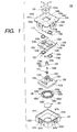
- Fig. 1 is an exploded perspective view for illustrating a multi-directional slide switch 100 of a preferred embodiment of the present invention.
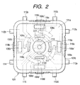
- Fig. 2 is a top plan view for showing a wafer 101 related to the multi-directional slide switch 100 of a preferred embodiment of the present invention.
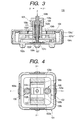
- Fig. 3 is a view in longitudinal section for showing the multi-directional slide switch 100 of a preferred embodiment of the present invention.
- Fig. 4 is a top plan view in partial section for illustrating the multi-directional slide switch 100 of a preferred embodiment of the present invention and for showing an assembled state of the first slide member 102.
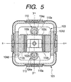
- Fig. 5 is a top plan view in partial section for illustrating the multi-directional slide switch 100 of a preferred embodiment of the present invention and for showing an assembled state of the second slide member 103.
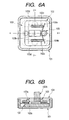
- Figs. 6A and 6B are illustrative views for illustrating the multi-directional slide switch 100 of a preferred embodiment of the present invention in which 6A is an illustrative view for showing a switching operation for a direction of x+ of an operating knob 102b and 6B is a front elevational view in partial section of it.
- Fig. 7 is an illustrative view for illustrating the multi-directional slide switch 100 of a preferred embodiment of the present invention and for showing a switching operation for a direction of y+ of an operating knob 102b.
- Fig. 8 is an illustrative view for illustrating the multi-directional slide switch 100 of a preferred embodiment of the present invention and for showing a slant switching operation of an operating knob 102b toward a direction of (x+, y+).
- Fig. 9 is a top plan view with a partial section for illustrating the multi-directional slide switch 300 of a preferred embodiment of the present invention and for showing an assembled state of a first slide member 302.
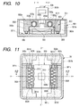
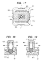
- Fig. 10 is a sectional view taken along line 10-10 in Fig. 9 for illustrating the multi-directional slide switch 300 of another preferred embodiment of the present invention.
- Fig. 11 is a top plan view with a partial section for illustrating the multi-directional slide switch 300 of another preferred embodiment of the present invention and for showing an assembled state of the second slide member 303.
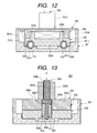
- Fig. 12 is a sectional view taken along line 12-12 of Fig. 11 for illustrating the multi-directional slide switch 300 of another preferred embodiment of the present invention.
- Fig. 13 is a longitudinal section for illustrating the multi-directional slide switch 300 of another preferred embodiment of the present invention.
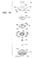
- Fig. 14 is an exploded perspective view for illustrating a multi-directional slide switch 500 of a still further preferred embodiment of the present invention.
- Fig. 15 is a top plan view for showing a wafer in regard to the multi-directional slide switch 500 of a still further preferred embodiment of the present invention.
- Fig. 16 is a longitudinal section for showing the multi-directional slide switch 500 of a still further preferred embodiment of the present invention.
- Fig. 17 is a top plan view with a partial section for illustrating a multi-directional slide switch 500 of a still further preferred embodiment of the present invention and for showing an assembled state of the first and second slide members.
- Fig. 18 is an illustrative view for illustrating a multi-directional slide switch 500 of a still further preferred embodiment of the present invention and for showing an initial state of engagement of the coil spring of the first slide member, and a ball and a sliding groove of the wafer.
- Fig. 19 is an illustrative view for illustrating a multi-directional slide switch 500 of a still further preferred embodiment of the present invention and for showing an engaging operation of the coil spring of the first slide member, and a ball and a sliding groove of the wafer.
- a multi-directional slide switch 100 of one preferred embodiment of the present invention will be described as follows.
- Fig. 1 is an exploded perspective view for illustrating a multi-directional slide switch of a preferred embodiment of the present invention
- Fig. 2 is a top plan view for showing a wafer 101
- Fig. 3 is a view in longitudinal section for showing a multi-directional slide switch 100
- Fig. 4 is a top plan view in partial section for illustrating an assembled state of a first slide member 102
- Fig. 5 is a top plan view in partial section for illustrating an assembled state of a second slide member 103
- Figs.6A and 6B are an illustrative view for illustrating a switching operation for a direction of x+ of an operating knob 102b and a front elevational view in partial section of it, respectively
- FIG. 7 is an illustrative view for illustrating a switching operation for a direction of y+ of an operating knob 102b
- Fig. 8 is an illustrative view for illustrating a slant switching operation of an operating knob 102b toward a direction of (x+, y+).
- the multi-directional slide switch 100 is mainly comprised of a wafer 101, a first slide member 102, a second slide member 103, a cover 104, a cap 105, a movable contact member 106, a metal contact 107, a pressing member 108, return springs 109, 110 (resilient members) and a coil spring 111.
- the wafer 101 is made of resin and as shown in Fig. 1, it is formed into a box-like shape constituted by a rectangular bottom plate 101a, and side walls 101b, 101b, 101b and 101b vertically installed from each of the sides of the bottom plate 101a.
- a circular recess 101c for use in arranging the metal contact 107.
- a recess 101b' formed with a predetermined width in a vertical direction, and at the central part of each of the recesses 101b' is formed a claw-like stopper section 101b", respectively.
- each of the external connecting terminals 112a, 112b, 112c, 112d; 113a, 113b; and 114, 115 formed of conductive metallic plates fixed by insert molding into the wafer 101 is protruded outwardly from the outer circumferential part of the wafer 101.
- a circular fixed contact member 116 formed of a conductive metallic plate fixed by an insert molding into the bottom plate 101a is exposed at the central part of the recess 101c of the bottom plate 101a and similarly, "D" type grand patterns 117, 117 formed of conductive metallic plates are oppositely exposed and formed at a part of the outer circumference of the recess 101c.
- rectangular fixed contact members 118a, 118b, 118c and 118d formed of conductive metallic plates fixed by insert molding and arranged along each of the side walls 101b of the bottom plate 101a are formed so as to be exposed at the bottom plate 101a, and similarly, rectangular grand patterns 119a, 119b, 119c and 119d enclosing the recess 101c, and arranged to become substantially in parallel with each of the fixed contact members 118a, 118b, 118c and 118d and formed of conductive metallic plates are formed so as to be exposed.
- the fixed contact member 116 is connected to the external connecting terminal 114 within the wafer 101 and similarly, the ground patterns 117, 117 and the external connecting terminal 115 are connected within the wafer 101.
- each of the fixed contact members 118a, 118b, 118c and 118d is connected to each of the external connecting terminals 112a, 112b, 112c and 112d, and the ground patterns 119a, 119b, 119c, and 119d are connected to the external connecting terminals 113a and 113b.
- a metal contact 107 comprised of a conductive dome-shaped leaf spring (the upward protruded shape in the figure) is inserted into and fixed to the recess 101c formed at the bottom plate 101a. At this time, a part of the outer circumference of the metal contact 107 is brought into contact with the ground pattern 117 (refer to Fig. 2) arranged in the recess 101c. In this way, at the recess 101c is formed a push switch 200 (refer to Fig. 3) in which the central part of the metal contact 107 is brought into contact with the fixed contact member 116 (refer to Fig. 2) when the metal contact 107 is pushed down, and the fixed contact member 116 is electrically conductive to the ground pattern 117 thereby carrying out the switching operation.
- the first slide member 102 is mainly comprised of a rectangular base 102a, a column-like operating knob 102b projected upwardly from the central part of the upper surface of the base 102a and integrally formed with it, and a pair of ribs 102c, 102c (the first engaging part) projected on the upper surface of the base 102a so as to hold the operating knob 102b and to be opposite to the direction of y-axis and integrally formed.
- the ribs 102c, 102c are arranged near the operating knob 102b and arranged in parallel to each other in a longitudinal direction of x-axis.
- each of the operating knob 102b and the base 102a is formed with through holes 102d, 102d' which pass through the operating knob 102b and the base 102a along the central axis of the operating knob 102b, respectively.
- the second slide member 103 is comprised of a rectangular plate-like base 103a; a longitudinal through hole 103b arranged at the central part of the base 103a and having as its x-axis direction a longitudinal direction; a pair of ribs 103c, 103c (the second engaging part) protruded on the upper surface of the base 103a while the through hole 103b being held, and oppositely faced to an x-axis direction and integrally formed; a pair of rectangular first guide sections 103d, 103d protruded at the lower surface of the base 103a while holding the through hole 103b, oppositely faced in a direction of y-axis and integrally formed; and a pair of round column-like protrusions 103e, 103e protruded at the lower surface of the base 103a and integrally formed so as to be oppositely faced in a direction of x-axis while the through hole 103b being held.
- the ribs 103c, 103c are arranged at the edge of the through hole 103b and in parallel to each other with longitudinal shape being applied in a direction of y-axis.
- the first guide sections 103d, 103d are arranged along the outer shape edge of the base 103a and arranged in parallel to each other in such a way that they have substantially the same length as that of the longitudinal direction of the rib 102c of the first slide member 102 (refer to Fig. 4).
- the protrusions 103e, 103e are arranged at the edge of the through hole 103b.
- the cover 104 is comprised of a rectangular plate-like base 104a; a rectangular insertion hole 104b arranged at the central part of the base 104a; a pair of rectangular second guide sections 104d, 104d protruded at the lower surface of the base 104a so as to be oppositely faced in a direction of x-axis while holding the through hole 104b and integrally formed; a pair of round column-like protrusions 104e, 104e protruded at the lower surface of the base 104a so as to be oppositely faced in a direction of y-axis while holding the through hole 104b and integrally formed; a fixing section 104c formed to be bent downward from the central part of each of the sides of outer shape of the base 104a; and a rectangular fixing hole 104c' formed to pass through the central part of each of the fixing sections 104c.
- the second guide sections 104d, 104d are arranged along the edge of the outer shape of the base 104a and arranged in parallel from each other in such a way that they have substantially the same length as that of the longitudinal length of the rib 103c of the second slide member 103 as a longitudinal shape in a direction of y-axis (refer to Fig. 5).
- the protrusions 104e, 104e are arranged at the edge of the insertion hole 104b.
- the cap 105 is a box-shaped member with its lower side being opened and the central part of the inner bottom surface (middle upper surface in Fig. 1) is formed with a through hole 105a.
- the movable contact member 106 is comprised of an electrical conductive metallic disc having a spring characteristic, provided with four resilient contact point legs 106a, 106b, 106c and 106d having each of the contact points 106a', 106b', 106c' and 106d' at the extremity ends formed to be bent along an outer circumference, the central part of the movable contact member 106 is formed with the through hole 106e.
- the pressing member 108 is a stepped shaft, wherein it is comprised of a large diameter shaft 108a; fine diameter shafts 108b, 108c each of which is coaxially and integrally formed in a vertical direction of the large diameter shaft 108a; and a pressing section 108d coaxially and integrally formed at the lower end of the fine diameter shaft 108c.
- the return springs 109, 110 are comprised of a helical torsion spring, each of the end sections 109b, 109b and 110b, 110b is formed to be substantially in a straight line in a tangential direction of winding portions 109a, 110a, respectively.
- the movable contact member 106 is fixed to the first slide member 102 after it is fitted to the fitting part (not shown) having the through hole 106e arranged at the rear surface side (the lower surface side in Fig. 1) of the first slide member 102 to carry out positioning. Then, when the operating knob 102b formed at the first slide member 102 is slid as described later, the movable contact member 106 is moved together with the first slide member 102 in an integral manner as the sliding operation is carried out.
- each of the end sections 109b, 109b of the two return springs 109 is arranged to be oppositely faced to each other, each of the end sections 109b, 109b is abutted against the end surface (restricting part) in a longitudinal direction (a direction of x-axis) of the first guide sections 103d, 103d formed at the lower surface of the base 103a and its position is restricted and engaged.
- the return springs 110, 110 by fitting the winding sections 110a, 110a of the return springs 110, 110 to the protrusions 104e, 104e formed at the base 104a.
- the end sections 110b, 110b of the two return springs 110 are arranged to be oppositely faced to each other, and further each of the end sections 110b, 110b is abutted against the end surface (restricting section) in a longitudinal direction (a direction of y-axis) of the second guide sections 104d, 104d formed at the lower surface of the base 104a, whereby its position is restricted and engaged.
- assembly of the second slide member 103 and the return springs 109, 109 is installed such that the through hole 103b formed at the base 103a of the second slide member 103 is movably and freely fitted in a direction of x-axis to the operating knob 102b of the first slide member 102 and laid over the first slide member 102.
- each of the outer surfaces of the ribs 102c, 102c of the first slide member 102 is engaged with opposing surfaces of the first guide sections 103d, 103d of the second slide member 103 and the first slide member 102 is slidably arranged in a direction of x-axis in respect to the second slide member 103.
- each of the ribs 102c at its longitudinal direction, is arranged between the end sections 109b, 109b, and 109b, 109b of the return springs 109a, 109a with a less amount of looseness, and when the first slide member 102 is moved by being operated in x+ or x- direction, the ends in longitudinal direction of the ribs 102c, 102c may deform any one of the end sections 109b, 109b of the return spring 109a in a moving direction, biace them and when the operation is stopped, the first slide member 102 can be returned again to a neutral position indicated in Fig. 4 by a resilient force of the return spring 109a.
- assembly of the first slide member 102, second slide member 103 and the return springs 109 is installed so as to be laid over the cover 104 by inserting the operating knob 102b of the first slide member 102 into the insertion hole 104b formed at the base 104a of the cover 104.
- each of the outer surfaces of the ribs 103c, 103c of the second slide member 103 is engaged with the opposing surfaces of the second guide sections 104d, 104d of the cover 104, and the second slide member 103 is slidably arranged in a direction of y-axis in respect to the cover 104.
- each of the ribs 103c at its longitudinal direction, is arranged between the end sections 110b, 110b, and 110b, 110b of the return springs 110a, 110a with a less amount of looseness, and when the second slide member 103 is moved by being operated in y+ or y- direction, the ends in longitudinal direction of the ribs 103c, 103c may deform any one of the end sections 110b, 110b of the return spring 110a in a moving direction, biace them and when the operation is stopped, the second slide member 103 can be returned again to a neutral position indicated in Fig. 5 by a resilient force of the return spring 110a.
- the first and second slide members 102, 103 and the cover 104 assembled in this way are set such that the multi-directional slide switch 100 is substantially assembled by a method wherein the first and second slide members 102, 103 are stored in the wafer 101 and the cover 104 is fixed to cover the upper opening of the wafer 101.
- each of the fixing sections 104c formed at the cover 104 shown in Fig. 1 is engaged with a recess 101b' formed at each of the side walls 101b of the wafer 101
- a stopper section 110b" is engaged with the fixing hole 104c (refer to Fig. 3) so as to prevent the cover 104 from being disengaged from the wafer 101.
- the operating knob 102b is slid in a crossing two-axis direction, namely, x-axis direction and y-axis direction as shown in Fig. 1, each of the first or second slide members 102, 103 is slid from the neutral position shown in Figs.4 and 5 to the direction of x-axis and the direction of y-axis, respectively, and the movable contact member 106 integrally formed with the first slide member 102 can be moved on the upper surface of the bottom plate 101a of the wafer 101 within a predetermined movable range in the x-, y- coordinates.
- the contact points 106a', 106b', 106c' and 106d' of the movable contact member 106 arranged at the rear surface side of the base 102a of the first slide member 102 are arranged between the fixed contact member 118a and the ground pattern 119a, between the fixed contact member 118b and the ground pattern 119b, between the fixed contact member 118c and the ground pattern 119c and between the fixed contact member 118d and the ground pattern 119d shown in Fig. 2, respectively, and they are resiliently contacted with the upper surface of the bottom plate 101a.
- This state corresponds to the initial position of the operating knob 102b, i.e. a neutral position where the switching operation by the operating knob 102b is not carried out in any directions.
- the coil spring 111 is inserted into the through hole 102d formed at the operating knob 102b of the first slide member 102 and then the pressing member 108 is inserted into it, and finally the cap 105 is fitted to the upper part of the operating knob 102b and assembling of the multi-directional slide switch 100 is completed.
- the coil spring 111 is fitted to the reduced diameter shaft 108c of the pressing member 108, the fine diameter shaft 108b is inserted into the through hole 105a formed at the cap 105 and the pressing section 108d is inserted into the through hole 102d'.
- the upper end of the fine diameter shaft 108b is depressed to enable the pressing member 108 to be displaced in a downward direction in Fig. 3 and its pressing operation can be carried out, resulting in that after pressing, as the load is released, the pressing member 108 returns back to the state shown in Fig. 3.
- the movable contact member 106 (refer to Fig. 1) is slid in a right side in Fig. 2 in respect to the fixed contact members 118a, 118b and ground patterns 119a, 119b formed at the bottom plate 101a of the wafer 101.
- the contact point 106a' at the extremity end of the resilient contact point leg 106a of the movable contact member 106 is brought into contact with the fixed contact member 118a.
- the contact point 106b' is brought into contact with the ground pattern 119b.
- the fixed contact member 118a and the ground pattern 119b are electrically conductive and the switching operation in a direction of x+ is carried out. Then, the signal under this operation is transmitted from the external connecting terminal 112a to the external side.
- the contact point 106b' of the movable contact member 106 is brought into contact with the fixed contact member 118b and the contact point 106a' is brought into contact with the ground pattern 119a (refer to Fig. 2).
- the fixed contact member 118b and the ground pattern 119b are electrically conductive and the switching operation in a direction of x- is carried out. Then, the signal under this operation is transmitted from the external connecting terminal 112a to the external side.
- the fixed contact member 118c and the ground pattern 119d are electrically conductive and a switching operation in a direction of y+ is carried out. Then, the signal under this operation is transmitted from the external connecting terminal 112c to the external side.
- the contact point 106d' of the movable contact member 106 is brought into contact with the fixed contact member 118d, and the contact point 106c' is brought into contact with the ground pattern 119c.
- the fixed contact member 118d and the ground pattern 119c are electrically conductive, resulting in that a switching operation in a direction of y-. Then, a signal under this operation is transmitted from the external connecting terminal 112d to the external side.
- each of the contact points 106a' and 106c' of the movable contact member 106 shown in Fig. 2 is brought into contact with the fixed contact members 118a, 118c by sliding the operating knob 102b in a slant rightward upper direction of (x+, y+).
- each of the contact points 106b', 106d' is brought into contact with the ground patterns 119b, 119d.
- the fixed contact members 118a, 118c and the ground patterns 119b, 119d are electrically conductive and a switching operation in a direction of (x+, y+) is carried out. Then, the signal under this operation is transmitted from the external connecting terminals 112a, 112c to the external side.
- each of the signals under these operations is transmitted from the external connecting terminals 112b, 112c and 112a, 112d, and 112b, 112d to the external side, respectively.
- the dome-shaped portion of the metal contact 107 is reversed, the metal contact 107 and the fixed contact member 116 are contacted to each other, thereby the fixed contact member 116 and the ground pattern 117 are electrically conductive and the push switch 200 performs a switching operation.
- the signal is transmitted from the external connecting terminal 114 shown in Fig. 2 to the external side as a digital signal.
- one operating knob 102b is slid in eight directions under combination of xy directions of x+, x-, y+, y-, and intermediate directions of x-axis and y-axis, i.e. slant directions of (x+, y+), (x+, y-), (x-, y+) and (x-, y-), thereby the multi-directional switching operation becomes possible and even in one unit of slide switch, it is possible to realize the multi-directional slide switch showing a superior operability.
- the multi-directional slide switch 300 of another preferred embodiment of the present invention will be described as follows.
- Fig. 9 is a top plan view with a partial section for illustrating an assembled state of a first slide member 302 of the multi-directional slide switch of another preferred embodiment of the present invention
- Fig. 10 is a sectional view taken along line 10-10 in Fig. 9
- Fig. 11 is a top plan view with a partial section for illustrating an assembled state of the second slide member 303
- Fig. 12 is a sectional view taken along line 12-12 of Fig. 11
- Fig. 13 is a longitudinal section for showing the multi-directional slide switch 300.
- the multi-directional slide switch 300 is mainly comprised of a wafer 301, a first slide member 302, a second slide member 303, a cover 304, movable contact members 306-1, 306-2, a push switch section 400, a pressing member 308, returning springs 309, 309 and 310, 310 (resilient member), and a coil spring 311.
- the case is constituted by the wafer 301 and the cover 304, wherein the wafer 301 is made of resin, and as shown in Fig. 9, it is formed into a box-like shape composed of a rectangular bottom plate 301a and side walls 301b vertically set from each of the sides in the bottom plate 301a, respectively.
- the push switch section 400 (refer to Fig. 13) having a fixed contact member and a metal contact (both of which are not shown) is installed at the central part of the bottom plate 301a.
- L-shaped fixed contact members 318a, 318b, 318c, 318d formed by conductive metallic plate are formed at four corners of the bottom plate 301a of the wafer 301 with their surfaces being exposed. Then, the fixed contact members 318a, 318b, 318c and 318d are connected to the external connecting terminals not shown installed in the wafer 301 so as to transmit the signals attained by the switching operation to the external side.
- both edges of the bottom plate 301a in a direction of x-axis are provided with protruded second guide sections 301c, 301c with y-axis being applied as a longitudinal direction on the upper surface of the bottom plate 301a and integrally formed.
- the first slide member 302 is mainly constituted by a base 302a of rectangular plate; a column-like operating knob 302b projected from the central section at the upper surface of the base 302a in an upward direction and integrally formed with it; a pair of protrusions 302e, 302e projected at the lower surface of the base 302a and integrally formed while they are being oppositely faced to both ends in a direction of y-axis with the x-axis being held therebetween; spring insertion grooves 302f, 302f formed at the lower surface of the base 302a with the x-axis being held therebetween and oppositely faced against both sides in a direction of y-axis; and a recess groove 302c (the first engaging section) formed at the lower surface of the base 302a with the x-axis being applied as a longitudinal direction.
- the protrusions 302e, 302e are arranged at both external edges of the base 302a and they are installed to be in parallel to each other with the x-axis being applied as a longitudinal shape.
- each of the spring insertion grooves 302f, 302f is arranged between x-axis and each of the protrusions 302e, 302e and they are arranged in parallel to each other with the x-axis being applied as a longitudinal shape.
- recess grooves 302g, 302g narrower than that of each of the spring insertion grooves 302f are connected from both end surfaces of each of the spring insertion grooves 302f and formed in a longitudinal direction.
- the operating knob 302b is formed with a through hole 302d passing through the operating knob 302b along the central axis, and further the base 302a is formed with a through hole 302d' connected to the through hole 302d.
- the second slide member 303 is constituted by a base 303a of rectangular plate; a rectangular through hole 303b arranged at the central section of the base 303a; spring insertion grooves 303f, 303f formed in a groove-shape at the lower surface of the base 303a while being oppositely faced at both sides in a direction of x-axis with the through hole 303b being held therebetween; first protruded guide sections 303d, 303d (refer to Figs.9 and 10) protruded on the upper surface of the base 303a with the x-axis being applied as a longitudinal direction and integrally formed; and two pairs of column-like protrusions 303g, 303g (refer to Figs.9 and 10) protruded at the upper surface of the base 303a and integrally formed with it while the through hole 303b is being held therebetween and oppositely faced in a direction of y-axis.
- the spring insertion grooves 303f, 303f are arranged along the external edge of the base 303a and they are arranged in parallel to each other while being applied as a longitudinal shape in a direction of y-axis. Further, each of the narrower recess grooves 303h, 303h than that of each of the spring insertion grooves 303f is connected from both end surfaces of each of the spring insertion grooves 303f in a longitudinal direction and formed in a longitudinal direction. Further, each of both external end surfaces of the base 303a in a direction of x-axis is applied as second engaging sections 303c, 303c.
- the cover 304 has a rectangular insertion hole 304a arranged at the central part thereof.
- the movable contact members 306-1, 306-2 shown in Figs.9 and 10 are formed by conductive metallic plate having spring characteristics, they are longitudinal belt in a direction of x-axis, therein each of the extremity ends folded and formed at both sides is provided with resilient contact point legs having contact points 306-1a, and 306-2a, 306-2b, respectively.
- the pressing member 308 is a stepped shaft, and as shown in Fig. 13, it is constituted by a large diameter shaft 108a, and fine diameter shafts 308b, 308c which are coaxially formed in a vertical direction of the large diameter shaft 308a.
- each of the return springs 309, 309 and 310, 310 is comprised of a coil spring (a compression spring).
- the movable contact members 306-1, 306-2 are fitted and fixed to the opposing surface of each of the protrusions 302e arranged at the first slide member 302 against the bottom plate 301a in such a way that they may be in parallel with the direction of x-axis.
- the operating knob 302b formed at the first slide member 302 is operated to slide, the movable contact members 306-1, 306-2 are moved in integral with the first slide member 302 in compliance with the sliding operation.
- each of the spring insertion grooves 302f formed at the lower surface of the base 302a of the first slide member 302 is arranged the return spring 309 while being installed between both end surfaces of the spring insertion groove 302f in the longitudinal direction, respectively.
- the end portions of the two return springs 309 are abutted against each of both end surfaces of the spring insertion groove 302f and their positions are restricted.
- each of the return springs 310, 310 between both end surfaces of the spring insertion groove 303f in its longitudinal direction.
- the end portions of the two return springs 310 are abutted against both end surfaces of the spring insertion groove 303f, resulting in that their positions are restricted.
- an assembly of the second slide member 303 and the return springs 309, 309 is arranged such that each of the second engaging sections 303c, 303c of the second slide member 303 is engaged with the opposing surfaces of the second guide sections 301c, 301c formed at the bottom plate 301a, and the second slide member 303 is slidably installed in a direction of y-axis in respect to the bottom plate 301a.
- the protrusions 301d, 301d formed at the bottom plate 301a are fitted to the recess grooves 303h, 303h arranged at both ends of each of the spring insertion grooves 303f formed at the second slide member 303. Then, when the second slide member 303 is moved under its operation in a direction of y+ or y-, any one of the end surfaces of each of the spring insertion grooves 303f in a longitudinal direction pushes the end part of the return spring 310 and biaces the other end of the return spring 310 against the protrusion 301d so as to cause the return spring 310 to be compressed. Then, when the operation is stopped, the second slide member 303 can be returned again to the neutral position shown in Fig. 11 with a resilient force of the return spring 310.
- an assembly comprised of the first slide member 302 and the return springs 309, 309 is constructed such that as shown in Figs.9 and 10, the recess grooves 302c, 302c formed at the first slide member 302 are engaged with the second guide sections 303d, 303d formed at the second slide member 303, and the first slide member 302 is slidably arranged with respect to the second slide member 303 in a direction of x-axis.
- the second slide members 302, 303 are stored in the wafer 301, and the cover 304 is fixed to cover the opening at the upper part of the wafer 301, thereby the multi-directional slide switch 300 becomes substantially assembled.
- the operating knob 302b arranged at the first slide member 302 can be slidably inserted into and passed through the through holes 304a formed at the cover 104 shown in Fig. 13.
- the operating knob 302b is slid in two crossing axial directions, i.e. in a direction of x-axis and a direction of y-axis, thereby each of the first slide member 302 or the second slide member 303 slides from the neutral position shown in Figs.9 and 11 in a direction of x-axis and in a direction of y-axis, and the movable contact members 306-1, 306-2 integrally formed with the first slide member 302 are movable on the upper surface of the bottom plate 301a of the wafer 301 within a predetermined movable range in the x, y coordinates.
- each of the contact points 306-1a, 306-1b and 306-2a, 306-2b of each of the movable contact members 306-1, 306-2 is arranged at the position where they may not be contacted with the fixed contact members 318a to 318d, respectively, and they are constructed to be resiliently contacted with the upper surface of the bottom plate 301a.
- This state becomes the initial position of the operating knob 302b, i.e. the neutral position where the switching operation by the operating knob 302b is not carried out in any direction.
- each of the contact points 306-1a, 306-1b and 306-2a, 306-2b is contacted under a predetermined combination with the fixed contact members 318a to 318d, thereby the multi-directional switching operation in x, y coordinates can be performed.
- the pressing member 308 is inserted from below and then the coil spring 311 is inserted into the through holes 302d, 302d' formed at each of the operating knob 302b of the first slide member 302 and the base 302a, and the through hole 303b formed at the second slide member 303, and finally a removal stopper member 303i for the coil spring 311 is fixed below the through hole 303b and assembling of the multi-directional slide switch 300 is completed.
- the fine diameter shaft 308b is inserted into the through hole 302d formed at the operating knob 302b, and the coil spring 311 is fitted to the reduced diameter shaft 308c of the pressing member 308.
- the pressing member 308 is displaced in a downward direction as viewed in the figure to depress the push switch 400 and a digital signal is transmitted from the external output terminal not shown to the outside part.
- the pressing member 308 may return back to the state shown in Fig. 13.
- the preferred embodiment of the present invention can attain the similar effect to that of the first preferred embodiment.
- a coil spring is used as the return springs 309, 310, so that it is possible to restrict a disturbance in spring load at the time of manufacturing the spring as compared with that of the helical torsion spring used in the first preferred embodiment and when the operating knob 302b is slid in the xy coordinates, a more uniform operating touch can be attained in any direction and further a high quality multi-directional slide switch can be provided.
- the compressive coil spring as the return springs 309, 310 enables a value of load of the spring to be set in a wider range as compared with that of the helical torsion spring (increasing the wire diameter in the helical torsion spring causes the spring thickness to be increased) without changing the spring length of the coil spring (by increasing the wire diameter of the spring material), and even the multi-directional slide switch having the same outer shape enables an operator to feel a load applying touch of the more wider range at the operating knob 302b, resulting in that the multi-directional slide switch having a variety of operating states can be provided.
- the push switches 200, 400 are formed by arranging the fixed contact members and the metal contacts at the bottom plates 101a, 301a of each of the bases 101, 301, they may not be restricted to this embodiment, but it may also be applicable that a single unit of push switch is arranged in place of the push switches 200, 400, respectively.
- a multi-directional slide switch 500 of a still further preferred embodiment of the present invention will be described as follows.
- Fig. 14 is an exploded perspective view for showing a multi-directional slide switch of a still further preferred embodiment of the present invention
- Fig. 15 is a top plan view for showing a wafer in regard to the multi-directional slide switch
- Fig. 16 is a longitudinal section for showing the multi-directional slide switch
- Fig. 17 is related to the multi-directional slide switch and is a top plan view with a partial section for showing an assembled state of the first and second slide members
- Fig. 18 is related to the multi-directional slide switch and is an illustrative view for showing an initial state of engagement of the coil spring of the first slide member, and a ball and a sliding groove of the wafer
- Fig. 19 is similarly related to the multi-directional slide switch and is an illustrative view for showing an initial state of engaging operation of the coil spring of the first slide member, and a ball and a sliding groove of the wafer.
- the multi-directional switch 500 is mainly comprised of a wafer 501, a first slide member 502, a second slide member 503, a cover 504, a movable contact member 506, a return coil spring 509 (a resilient member) and a ball 510 (a driving member).
- a case is constituted by a wafer 501 and a cover 504, the wafer 501 is made of resin, and as shown in Fig. 14, this is formed into a box-like shape constituted by a rectangular bottom plate 501a, and side walls 501b vertically set from each of the sides of the bottom plate 501a.
- a box-like shape constituted by a rectangular bottom plate 501a, and side walls 501b vertically set from each of the sides of the bottom plate 501a.
- an inverse conical-shaped sliding groove 501c to which a ball 510 is engaged and slidingly contacted with it.
- each of claw-like stoppers 501d that is fixed to a fixing part 504c of the cover 504 and engaged with it.
- a ground pattern 519 and some fixed contact members 518a, 518b, 518c and 518d composed of a conductive metallic plate while they are being exposed at the inner bottom surface. Then, the ground pattern 519 and fixed contact members 518a, 518b, 518c, 518d are connected within the wafer 501 to the external connecting terminals 512a, 512b, 512c, 512d, and 513a, 513b so as to transmit a signal through switching operation to an external side.
- the first slide member 502 is formed with a base 502a formed by a. rectangular plate; a column-like operating knob 502b protruded upwardly from the central part of the upper surface of the base 502a and integrally formed with it; protrusions 502c protruded at the upper surface of the base 502a while holding the operating knob 502b therebetween with being oppositely faced in a direction of y-axis; and a recess groove engaging part 502d enclosed by the protrusions 502c.
- a storing part 502e storing the movable contact member 506, and a storing hole 502f for the return coil spring 509 arranged in a rectangular column of the operating knob 502b.
- the second slide member 503 is formed by a rectangular flat plate and its shape is formed into a rectangle with its x-axis direction being longitudinal one in respect to its y-axis direction.
- a rectangular window hole 503a with its x-axis direction being applied as a longitudinal one is similarly arranged at the central part.
- the aforesaid operating knob 502b is freely fitted to the window hole 503a in such a way that it can be moved in a longitudinal direction, i.e. the x-axis direction.
- a second slide member 503 is engaged with the recess groove engaging part 502d of the aforesaid first slide member 502, wherein the recess groove engaging part 502d and the second slide member 503 can be moved in the x-axis direction.
- the cover 504 is comprised of a base 504a of rectangular plate; a rectangular insertion hole 504b arranged at the central part of the base 504a; fixing sections 504c bent downwardly from the central part of each of the external sides of the base 504a; and fixing holes 504d arranged at each of the fixing sections 504c and engaged with the stopper 501d of the wafer 501.
- the insertion hole 504b is formed to be opened larger by a moving stroke than that of the external shape of the operating knob 502b in such a way that the operating knob 502b of the first slide member 502 is protruded and movable in both x-axis and y-axis directions.
- the movable contact member 506 is formed by a conductive metallic disc having a spring resiliency, wherein there are provided four resilient contact point legs 506b having each of contact points 506a at the extremity ends folded along the outer circumference, and the central part of the movable contact member 506 is formed with a through hole 506c.
- the return coil spring 509 is stored in the storing hole 502f of the operating knob 502b, and a ball 510 is biased against the sliding groove 510c of the wafer 501.
- the movable contact member 506 is fixed to the storing part 502e arranged at the lower surface side of the base 502a of the first slide member 502.
- both coil spring 509 and ball 510 are stored in the storing hole 502f of the operating knob 502b.
- the second slide member 503 is fitted to the recess groove engaging part 502d at the upper surface side under a state in which the window hole 503a is freely fitted to the operating knob 502b.
- a ball 510 is abutted against the sliding groove 501c arranged at the central part of the bottom plate 501a of the wafer 501, and further each of the contact points 506a of the movable contact member 506 is abutted against an intermediate section among the fixed contact members 518a, 518b, 518c, 518d and the ground pattern 519.
- the cover 504 is fixed in such a way that it may cover the upper surface of the opening of the wafer 501, and a fixing hole 504d arranged at each of the fixing sections 504c is engaged with the stopper 501d of the wafer 501.
- the operating knob 502b of the first slide member 502 is protruded out of the insertion hole 504b, and the operating knob 502b is arranged such that it can be moved in the x-axis and y-axis directions.
- the ball 510 of the first slide member 502 is located at the central deepest position of the sliding groove 501c of the wafer 501 as shown in Figs.16 and 18, and the operating knob 502b is positioned at the central section of the insertion hole 504b of the cover 504.
- each of the contact points 506a of the movable contact member 506 is not abutted against the fixed contact members 518a, 518b, 518c, 518d and the ground pattern 519, but spaced apart from them.
- the first slide member 502 is operated such that the operating knob 502b is guided by the window hole 503a of the second slide member 503 and by a pair of sides opposed to each other with the recess groove engaging sections 502d holding the x-axis of the second slide member 503.
- the second slide member 503 is not moved due to the fact that a pair of sides opposing to each other with the y-axis being held therebetween are abutted against the inner surface of the side walls 501b of the wafer 501, but only the first slide member 502 is moved.
- the first slide member 502 is slid and moved together with the second slide member 503.
- the second slide member 503 can be moved only in the direction of y-axis with a pair of sides opposing to each other to hold the y-axis of the second slide member 503 being guided at the opposing inner sides of the wafer 501.
- the coil spring 509 is compressed and a returning force returning back to its initial position with a biasing force of the coil spring 509 is generated at the ball 510.
- the contact point 506a of the movable contact member 506 is moved in the direction of y- and contacted with the fixed contact member 518d and the ground pattern 519.
- the fixed contact member 518d and the ground pattern 519 are made to be electrically conductive and the switching operation in the direction of y- is carried out. Then, a signal attained under this operation is transmitted from the external connecting terminal 512d to the external side.
- the ball 510 returns back to the initial position with the biasing force of the coil spring 509, and along with this operation, the operating knob 502b also returns back to the initial position.
- the first slide member 502 is slid and moved together with the second slide member 503, although the second slide member 503 is moved only in the direction of y-, and the first slide member 502 can be slid and moved also in the direction of x-axis while the knob 502b is being guided by the window hole 503a of the second slide member 503 and the recess groove engaging section 502d is being guided by a pair of opposing sides with the x-axis of the second slide member 530 being held therebetween. Accordingly, the first slide member 502 is slid and moved in the slant direction of the intermediate direction of each of x-axis and y-axis.
- each of the contact points 506a of the movable contact member 506 moves in a slant direction of an intermediate one of the direction of x- and the direction of y-, and further it is brought into contact with each of the fixed contact members 518b, 518b and the ground pattern 519.
- the fixed contact members 518b, 518d and the ground pattern 519 are made to be electrically conductive, a switching operation in a slant direction of an intermediate one of the direction of x- and the direction of y- is carried out. Then, a signal attained under this operation is transmitted from the external connecting terminals 512b, 512d to the external side.
- the ball 510 returns back to the initial position with the biasing force of the coil spring 509, and along with this operation, the operating knob 502b also returns back to the initial position.
- the push switch section is not formed in the preferred embodiment of the present invention, it may also be applicable that another separate push switch is arranged.
- the driving member stored in the first slide member 502 is constituted by the ball 510, the driving member is not limited to the ball-shape, but a rod-like member can be used if its extremity end is spherical.
- one coil spring 509 is used as the return spring and a multi-directional operation and returning with one coil spring 509 can be carried out, so that the number of component parts can be reduced and its less-expensive price can be attained. Further, since the coil spring 509 is stored in the operating knob 502b, its small-sized unit can be realized and its assembling characteristic may also be improved.
- the second slide member 503 is formed by a rectangular flat plate and the upper surface of the first slide member is formed with a recess groove engaging section guided by a pair of opposing sides of the second slide member and slidably engaged with it, its structure becomes simple, its small-sized unit can be attained and its assembling characteristic can also be improved.
- a case having a fixed contact member and a first slide member and a second slide member arranged in the case and slidably guided in each of crossing two axes direction, respectively, wherein the first slide member is provided with an operating knob and a movable contact member, the operating knob is projected outside the case, the operating knob is operated to a predetermined position of two-axis coordinates, thereby each of the first slide member and the second slid member is slid in the two-axis direction, the movable contact member is brought into contact with the fixed contact member, and a multi-directional switching operation of the operating knob is carried out, so that the multi-directional switching operation can be carried out by operating one operating knob and its operating characteristic can be improved.
- the slide of the movable contact member in respect to the fixed contact member can be constituted mainly by the two component parts of the first and second slide members, the slide mechanism can be simplified and the number of component parts can be reduced. Further, with such an arrangement as above, since the slide mechanisms of the first and second slide members can be constituted by a combination of the simple motion, the positive switching operation can be performed even with the several times of operation of the operating knob, whereby it is possible to provide the multi-directional slide switch having its reliability in operation improved.
- the second slide member Since the movable contact member is fitted to and fixed to a rear surface opposite to the operating knob of the first slide member, the second slide member is provided with a through hole through which the operating knob can freely fit in a sliding direction of the first slide member, and the operating knob inserted into the through hole is projected outside the case, it becomes possible to assemble the first slide member into the second slide member and overlap them to each other and their assembling may easily be carried out.
- the case is comprised of a wafer having a fixed contact member at its inner bottom surface and a cover mounted so as to cover the wafer, a rear surface of the second slide member is provided with a first guide section, the first slide member is provided with a first engaging section slidably engaged with the first guide section, in addition, the cover is provided with an insertion hole through which the operating knob is projected outwardly and its rear surface is provided with a second guide section, further, the second slide member is provided with a second engaging section slidably engaged with the second guide section, each of the first slide member and second slide member is slidably guided in the two-axis direction in respect to the cover. Therefore, it is possible to provide a multi-directional slide switch capable of restricting either motion or rotation of each of the first and second slide members in the direction other than the two-axis directions and performing the positive switching operation
- each of the second slide member and the rear surface of the cover is provided with a resilient member for use in returning each of the first slide member and second slide member to a predetermined initial position with a resilient force, respectively, when the operating knob is not operated, it becomes possible to set the multi-directional switch to a state in which the switching is not performed in any directions, a so-called neutral state, and it is possible to provide a multi-directional slide switch in which disadvantage to cause the switching operation to be performed to the contrary of the operator's intention is eliminated and its operating characteristic is improved.
- the resilient members are helical torsion springs
- the helical torsion springs are arranged at both sides in a sliding direction of each of the first engaging section and second engaging section, respectively, the first and second engaging sections are biased by the end sections of the helical torsion springs against sliding motions of the first engaging section and the second engaging section and returned back to the their initial positions, so that the less-expensive helical torsion springs of the resilient members enable the component cost of the return mechanism of the operating knob to be reduced, thereby the cost of the multi-directional slide switch can be reduced.
- each of the second slide member and the rear surface of the cover is provided with a restricting section for restricting the end section of the helical torsion spring to a predetermined position, when the first and second slide members are returned back to their initial positions, the end section of the helical torsion spring is not set free, but it is restricted to a predetermined position, resulting in that the non-uniform biasing force is not received from both sides of the first and second engaging sections and the initial positions of the first slide member and the second slide member are not displaced from the desired positions, the operating knob can be always stably returned back to its predetermined initial position
- the case is comprised of a wafer having a fixed contact member at its inner bottom surface, and a cover mounted so as to cover the wafer
- the second slide member is formed by a rectangular flat plate
- an upper surface of the first slide member is formed with a recess groove engaging section guided by one of a pair of opposing sides of the second slide member and slidably engaged with it
- the other of a pair of opposing sides of the second slide member is slidably engaged with an inner side surface of the side wall of the wafer
- the cover is provided with a through hole through which the operating knob is projected outside
- each of the first slide member and second slide member is slidably guided with respect to the wafer in the two-axis direction, so that it is possible to provide a multi-directional slide switch in which the first slide member is guided by the side of the second slide member and the second slide member is guided by the inner surface of the side wall of the wafer, either a motion or rotation of the first and second slide members in respect to the case in a direction other than
- the first slide member is provided with a resilient member for returning the first slide member and second slide member to predetermined initial positions by resilient force and with a driving member biased by the resilient member
- the wafer is provided with an inverse conical sliding groove to which the driving member is engaged, so that a multi-directional operation and returning can be carried out with one coil spring, the number of component parts can be reduced, and its less-expensive state can be attained.
- the resilient member is formed by a coil spring and the driving member is formed by a ball member, so that a positive operation and returning can be carried out by a simple configuration.
- the case is provided with a push switch
- the operating knob is provided with a pressing member
- the pressing member is pressed and displaced in a direction crossing at a right angle with the two-axis direction
- the push switch is depressed to perform a switching operation, so that it is possible to provide a multi-directional slide switch in which not only the multi-directional sliding operation, but also the push switch can be carried out by the switching operation, for example, a scrolling at a displayed screen can be performed by the multi-directional sliding operation, inputting means required in other functions becomes possible under a switching operation of the push switch performed under the pressing operation of the pressing member and further its operability is superior.
Landscapes
- Switches With Compound Operations (AREA)
- Position Input By Displaying (AREA)
Abstract
Description
- This invention relates to a multi-directional slide switch used, for example, for scroll operating the content of the screen display for various kinds of electronic equipment, and more particularly, a multi-slide switch that is preferable for improving its operability.
- In the prior art, the slide switch was used for performing a scroll operation of the content displayed in the screen of various kinds of electronic equipment, for example. In the case that only one-directional operation was satisfactory for the scroll operation, its accommodation for it was possible by applying one directional slide switch where an operator could operate one directional switching operation.
- However, in the case that a map display screen or the like in a car navigation system commercially available in recent years is operated in scroll manner, at least two-directional scrolling operations for x-axis and y-axis, respectively, are required, resulting in that a demand for a slide switch corresponding to a multi-directional switching operation has been increased.
- However, in the case where the switching operations for an x-axis direction and a y-axis direction were required, two one-directional slide switch was arranged in compliance with each of the x-axis direction and the y-axis direction, an operator once operated one slide switch, thereafter the operator handed off the switch and had to operate the other slide switch, whereby its workability was not superior.
- It is an object of the present invention to provide a multi-directional slide switch in which a multi-directional switching operation can be carried out with one slide switch and its operability can be improved.
- As a first solving means for solving the aforesaid problem, the present invention is comprised of a case having a fixed contact member and a first slide member and a second slide member arranged in the case and slidably guided in crossing two axes direction, respectively, and is characterized in that the first slide member is provided with an operating knob and a movable contact member, the operating knob is projected outside the case, the operating knob is operated to a predetermined position of two-axis coordinates, thereby each of the first slide member and the second slid member is slid in the two-axis direction, the movable contact member is brought into contact with the fixed contact member, and a multi-directional switching operation of the operating knob is carried out.
- Further, as a second solving means, the present invention is characterized in that the movable contact member is fitted to and fixed to a rear surface opposite to the operating knob of the first slide member, the second slide member is provided with a through hole through which the operating knob can freely fit in a sliding direction of the first slide member, and the operating knob inserted into the through hole is projected outside the case.
- Further, as a third solving means, the present invention is characterized in that the case is comprised of a wafer having the fixed contact member at its inner bottom surface and a cover mounted so as to cover the wafer, a rear surface of the second slide member is provided with a first guide section, the first slide member is provided with a first engaging section slidably engaged with the first guide section, in addition, the cover is provided with an insertion hole through which the operating knob is projected outwardly and its rear surface is provided with a second guide section, further, the second slide member is provided with a second engaging section slidably engaged with the second guide section, each of the first slide member and second slide member is slidably guided in the two-axis direction in respect to the cover.
- Further, as a fourth solving means, the present invention is characterized in that each of the second slide member and the rear surface of the cover is provided with a resilient member for use in returning each of the first slide member and second slide member to a predetermined initial position with a resilient force, respectively.
- Further, as a fifth solving means, the present invention is characterized in that the resilient member is a helical torsion spring, the helical torsion springs are arranged at both sides in a sliding direction of each of the first engaging section and a second engaging section, respectively, the first and second engaging sections are biased by the end sections of the helical torsion springs against sliding motions of the first engaging section and the second engaging section and returned back to the their initial positions.
- Further, as a sixth solving means, the present invention is characterized in that each of the second slide member and the rear surface of the cover is provided with a restricting section for restricting the end section of the helical torsion spring to a predetermined position.
- Further, as a seventh solving means, the present invention is characterized in that the case is comprised of a wafer having the fixed contact member at its inner bottom surface and a cover mounted so as to cover the wafer, the second slide member is formed by a rectangular flat plate, an upper surface of the first slide member is formed with a recess groove engaging section guided by one of a pair of opposing sides of the second slide member and slidably engaged with it, the other of a pair of opposing sides of the second slide member is slidably engaged with an inner side surface of the side wall of the wafer, the cover is provided with an insertion hole through which the operating knob is projected outside, and each of the first slide member and second slide member is slidably guided with respect to the wafer in the two-axis direction.
- Further, as an eighth solving means, the present invention is characterized in that the first slide member is provided with a resilient member for returning the first slide member and second slide member to predetermined initial positions by resilient force and with a driving member biased by the resilient member, the wafer is provided with an inverse conical sliding groove to which the driving member is engaged.
- Further, as a ninth solving means, the present invention is characterized in that the resilient member is formed by a coil spring and the driving member is formed by a ball member.
- Further, as a tenth solving means, the present invention is characterized in that the case is provided with a push switch, the operating knob is provided with a pressing member, the pressing member is pressed and displaced in a direction crossing at a right angle with the two-axis direction, the push switch is depressed to perform a switching operation.
- Fig. 1 is an exploded perspective view for illustrating a
multi-directional slide switch 100 of a preferred embodiment of the present invention. - Fig. 2 is a top plan view for showing a
wafer 101 related to themulti-directional slide switch 100 of a preferred embodiment of the present invention. - Fig. 3 is a view in longitudinal section for showing the
multi-directional slide switch 100 of a preferred embodiment of the present invention. - Fig. 4 is a top plan view in partial section for illustrating the
multi-directional slide switch 100 of a preferred embodiment of the present invention and for showing an assembled state of thefirst slide member 102. - Fig. 5 is a top plan view in partial section for illustrating the
multi-directional slide switch 100 of a preferred embodiment of the present invention and for showing an assembled state of thesecond slide member 103. - Figs. 6A and 6B are illustrative views for illustrating the
multi-directional slide switch 100 of a preferred embodiment of the present invention in which 6A is an illustrative view for showing a switching operation for a direction of x+ of anoperating knob 102b and 6B is a front elevational view in partial section of it. - Fig. 7 is an illustrative view for illustrating the
multi-directional slide switch 100 of a preferred embodiment of the present invention and for showing a switching operation for a direction of y+ of anoperating knob 102b. - Fig. 8 is an illustrative view for illustrating the
multi-directional slide switch 100 of a preferred embodiment of the present invention and for showing a slant switching operation of anoperating knob 102b toward a direction of (x+, y+). - Fig. 9 is a top plan view with a partial section for illustrating the
multi-directional slide switch 300 of a preferred embodiment of the present invention and for showing an assembled state of afirst slide member 302. - Fig. 10 is a sectional view taken along line 10-10 in Fig. 9 for illustrating the
multi-directional slide switch 300 of another preferred embodiment of the present invention. - Fig. 11 is a top plan view with a partial section for illustrating the
multi-directional slide switch 300 of another preferred embodiment of the present invention and for showing an assembled state of thesecond slide member 303. - Fig. 12 is a sectional view taken along line 12-12 of Fig. 11 for illustrating the
multi-directional slide switch 300 of another preferred embodiment of the present invention. - Fig. 13 is a longitudinal section for illustrating the
multi-directional slide switch 300 of another preferred embodiment of the present invention. - Fig. 14 is an exploded perspective view for illustrating a
multi-directional slide switch 500 of a still further preferred embodiment of the present invention. - Fig. 15 is a top plan view for showing a wafer in regard to the
multi-directional slide switch 500 of a still further preferred embodiment of the present invention. - Fig. 16 is a longitudinal section for showing the
multi-directional slide switch 500 of a still further preferred embodiment of the present invention. - Fig. 17 is a top plan view with a partial section for illustrating a
multi-directional slide switch 500 of a still further preferred embodiment of the present invention and for showing an assembled state of the first and second slide members. - Fig. 18 is an illustrative view for illustrating a
multi-directional slide switch 500 of a still further preferred embodiment of the present invention and for showing an initial state of engagement of the coil spring of the first slide member, and a ball and a sliding groove of the wafer. - Fig. 19 is an illustrative view for illustrating a
multi-directional slide switch 500 of a still further preferred embodiment of the present invention and for showing an engaging operation of the coil spring of the first slide member, and a ball and a sliding groove of the wafer. - Referring now to Figs.1 to 8 in the drawings, a
multi-directional slide switch 100 of one preferred embodiment of the present invention will be described as follows. - Fig. 1 is an exploded perspective view for illustrating a multi-directional slide switch of a preferred embodiment of the present invention, Fig. 2 is a top plan view for showing a
wafer 101, Fig. 3 is a view in longitudinal section for showing amulti-directional slide switch 100, Fig. 4 is a top plan view in partial section for illustrating an assembled state of afirst slide member 102, Fig. 5 is a top plan view in partial section for illustrating an assembled state of asecond slide member 103, Figs.6A and 6B are an illustrative view for illustrating a switching operation for a direction of x+ of anoperating knob 102b and a front elevational view in partial section of it, respectively, Fig. 7 is an illustrative view for illustrating a switching operation for a direction of y+ of anoperating knob 102b, and Fig. 8 is an illustrative view for illustrating a slant switching operation of anoperating knob 102b toward a direction of (x+, y+). - As shown in Fig. 1, the
multi-directional slide switch 100 is mainly comprised of awafer 101, afirst slide member 102, asecond slide member 103, acover 104, acap 105, amovable contact member 106, ametal contact 107, apressing member 108,return springs 109, 110 (resilient members) and acoil spring 111. - Next, each of the members will be described as follows.
- At first, a case is constituted by the
wafer 101 and thecover 104, thewafer 101 is made of resin and as shown in Fig. 1, it is formed into a box-like shape constituted by arectangular bottom plate 101a, andside walls bottom plate 101a. In addition, at the central part of thebottom plate 101a is formed acircular recess 101c for use in arranging themetal contact 107. At the central part of the outer side surface of each of theside walls 101b is arranged arecess 101b' formed with a predetermined width in a vertical direction, and at the central part of each of therecesses 101b' is formed a claw-like stopper section 101b", respectively. - Further, as shown in Fig. 2, at the
wafer 101, each of theexternal connecting terminals wafer 101 is protruded outwardly from the outer circumferential part of thewafer 101. - In addition, a circular fixed
contact member 116 formed of a conductive metallic plate fixed by an insert molding into thebottom plate 101a is exposed at the central part of therecess 101c of thebottom plate 101a and similarly, "D" typegrand patterns recess 101c. - Further, rectangular fixed
contact members side walls 101b of thebottom plate 101a are formed so as to be exposed at thebottom plate 101a, and similarly, rectangulargrand patterns recess 101c, and arranged to become substantially in parallel with each of the fixedcontact members - Then, the
fixed contact member 116 is connected to theexternal connecting terminal 114 within thewafer 101 and similarly, theground patterns terminal 115 are connected within thewafer 101. In addition, each of the fixedcontact members external connecting terminals ground patterns terminals - In addition, as shown in Figs.1 and 3, a
metal contact 107 comprised of a conductive dome-shaped leaf spring (the upward protruded shape in the figure) is inserted into and fixed to therecess 101c formed at thebottom plate 101a. At this time, a part of the outer circumference of themetal contact 107 is brought into contact with the ground pattern 117 (refer to Fig. 2) arranged in therecess 101c. In this way, at therecess 101c is formed a push switch 200 (refer to Fig. 3) in which the central part of themetal contact 107 is brought into contact with the fixed contact member 116 (refer to Fig. 2) when themetal contact 107 is pushed down, and thefixed contact member 116 is electrically conductive to theground pattern 117 thereby carrying out the switching operation. - Next, as shown in Fig. 1, the
first slide member 102 is mainly comprised of arectangular base 102a, a column-like operating knob 102b projected upwardly from the central part of the upper surface of thebase 102a and integrally formed with it, and a pair ofribs base 102a so as to hold theoperating knob 102b and to be opposite to the direction of y-axis and integrally formed. In this case, theribs operating knob 102b and arranged in parallel to each other in a longitudinal direction of x-axis. - In addition, as shown in Figs.1 and 3, each of the
operating knob 102b and thebase 102a is formed with throughholes operating knob 102b and thebase 102a along the central axis of theoperating knob 102b, respectively. - Next, as shown in Fig. 1, the
second slide member 103 is comprised of a rectangular plate-like base 103a; a longitudinal throughhole 103b arranged at the central part of thebase 103a and having as its x-axis direction a longitudinal direction; a pair ofribs base 103a while thethrough hole 103b being held, and oppositely faced to an x-axis direction and integrally formed; a pair of rectangularfirst guide sections base 103a while holding the throughhole 103b, oppositely faced in a direction of y-axis and integrally formed; and a pair of round column-like protrusions base 103a and integrally formed so as to be oppositely faced in a direction of x-axis while the throughhole 103b being held. - Further, the
ribs through hole 103b and in parallel to each other with longitudinal shape being applied in a direction of y-axis. In addition, thefirst guide sections base 103a and arranged in parallel to each other in such a way that they have substantially the same length as that of the longitudinal direction of therib 102c of the first slide member 102 (refer to Fig. 4). In addition, theprotrusions through hole 103b. - Next, as shown in Fig. 1, the
cover 104 is comprised of a rectangular plate-like base 104a; arectangular insertion hole 104b arranged at the central part of thebase 104a; a pair of rectangularsecond guide sections base 104a so as to be oppositely faced in a direction of x-axis while holding the throughhole 104b and integrally formed; a pair of round column-like protrusions base 104a so as to be oppositely faced in a direction of y-axis while holding the throughhole 104b and integrally formed; afixing section 104c formed to be bent downward from the central part of each of the sides of outer shape of thebase 104a; and arectangular fixing hole 104c' formed to pass through the central part of each of thefixing sections 104c. - Further, the
second guide sections base 104a and arranged in parallel from each other in such a way that they have substantially the same length as that of the longitudinal length of therib 103c of thesecond slide member 103 as a longitudinal shape in a direction of y-axis (refer to Fig. 5). In addition, theprotrusions insertion hole 104b. - Next, the
cap 105 is a box-shaped member with its lower side being opened and the central part of the inner bottom surface (middle upper surface in Fig. 1) is formed with a throughhole 105a. - Next, the
movable contact member 106 is comprised of an electrical conductive metallic disc having a spring characteristic, provided with four resilientcontact point legs movable contact member 106 is formed with the throughhole 106e. - Then, the pressing
member 108 is a stepped shaft, wherein it is comprised of alarge diameter shaft 108a;fine diameter shafts large diameter shaft 108a; and apressing section 108d coaxially and integrally formed at the lower end of thefine diameter shaft 108c. - Then, the return springs 109, 110 are comprised of a helical torsion spring, each of the
end sections portions - Next, referring to Figs.1 to 5, an assembled state of each of the members and their operation will be described.
- At first, the
movable contact member 106 is fixed to thefirst slide member 102 after it is fitted to the fitting part (not shown) having the throughhole 106e arranged at the rear surface side (the lower surface side in Fig. 1) of thefirst slide member 102 to carry out positioning. Then, when the operatingknob 102b formed at thefirst slide member 102 is slid as described later, themovable contact member 106 is moved together with thefirst slide member 102 in an integral manner as the sliding operation is carried out. - In addition, at the lower surface of the
base 103a of thesecond slide member 103 are installed the return springs 109, 109 by fitting the windingsections protrusions base 103a. At this time, as shown in Fig. 4, each of theend sections end sections first guide sections base 103a and its position is restricted and engaged. - Similarly, at the lower surface of the
base 104a of thecover 104 are installed the return springs 110, 110 by fitting the windingsections protrusions base 104a. At this time, as shown in Fig. 5, theend sections end sections second guide sections base 104a, whereby its position is restricted and engaged. - Then, assembly of the
second slide member 103 and the return springs 109, 109 is installed such that the throughhole 103b formed at thebase 103a of thesecond slide member 103 is movably and freely fitted in a direction of x-axis to the operatingknob 102b of thefirst slide member 102 and laid over thefirst slide member 102. - At this time, as shown in Fig. 4, each of the outer surfaces of the
ribs first slide member 102 is engaged with opposing surfaces of thefirst guide sections second slide member 103 and thefirst slide member 102 is slidably arranged in a direction of x-axis in respect to thesecond slide member 103. - Then, each of the
ribs 102c, at its longitudinal direction, is arranged between theend sections first slide member 102 is moved by being operated in x+ or x- direction, the ends in longitudinal direction of theribs end sections return spring 109a in a moving direction, biace them and when the operation is stopped, thefirst slide member 102 can be returned again to a neutral position indicated in Fig. 4 by a resilient force of thereturn spring 109a. - In addition, assembly of the
first slide member 102,second slide member 103 and the return springs 109 is installed so as to be laid over thecover 104 by inserting the operatingknob 102b of thefirst slide member 102 into theinsertion hole 104b formed at thebase 104a of thecover 104. - At this time, as shown in Fig. 5, each of the outer surfaces of the
ribs second slide member 103 is engaged with the opposing surfaces of thesecond guide sections cover 104, and thesecond slide member 103 is slidably arranged in a direction of y-axis in respect to thecover 104. - Then, each of the
ribs 103c, at its longitudinal direction, is arranged between theend sections second slide member 103 is moved by being operated in y+ or y- direction, the ends in longitudinal direction of theribs end sections return spring 110a in a moving direction, biace them and when the operation is stopped, thesecond slide member 103 can be returned again to a neutral position indicated in Fig. 5 by a resilient force of thereturn spring 110a. - The first and
second slide members cover 104 assembled in this way are set such that themulti-directional slide switch 100 is substantially assembled by a method wherein the first andsecond slide members wafer 101 and thecover 104 is fixed to cover the upper opening of thewafer 101. At this time, each of the fixingsections 104c formed at thecover 104 shown in Fig. 1 is engaged with arecess 101b' formed at each of theside walls 101b of thewafer 101, astopper section 110b" is engaged with the fixinghole 104c (refer to Fig. 3) so as to prevent thecover 104 from being disengaged from thewafer 101. - Then, the operating
knob 102b is slid in a crossing two-axis direction, namely, x-axis direction and y-axis direction as shown in Fig. 1, each of the first orsecond slide members movable contact member 106 integrally formed with thefirst slide member 102 can be moved on the upper surface of thebottom plate 101a of thewafer 101 within a predetermined movable range in the x-, y- coordinates. - In addition, when the first and
second slide members movable contact member 106 arranged at the rear surface side of thebase 102a of thefirst slide member 102 are arranged between thefixed contact member 118a and theground pattern 119a, between thefixed contact member 118b and theground pattern 119b, between thefixed contact member 118c and theground pattern 119c and between thefixed contact member 118d and theground pattern 119d shown in Fig. 2, respectively, and they are resiliently contacted with the upper surface of thebottom plate 101a. This state corresponds to the initial position of the operatingknob 102b, i.e. a neutral position where the switching operation by the operatingknob 102b is not carried out in any directions. - In turn, as shown in Fig. 3, at first, the
coil spring 111 is inserted into the throughhole 102d formed at the operatingknob 102b of thefirst slide member 102 and then thepressing member 108 is inserted into it, and finally thecap 105 is fitted to the upper part of the operatingknob 102b and assembling of themulti-directional slide switch 100 is completed. In this case, when thecoil spring 111 is fitted to the reduceddiameter shaft 108c of thepressing member 108, thefine diameter shaft 108b is inserted into the throughhole 105a formed at thecap 105 and thepressing section 108d is inserted into the throughhole 102d'. Then, the upper end of thefine diameter shaft 108b is depressed to enable thepressing member 108 to be displaced in a downward direction in Fig. 3 and its pressing operation can be carried out, resulting in that after pressing, as the load is released, the pressingmember 108 returns back to the state shown in Fig. 3. - Then, the switching operation of the
multi-directional slide switch 100 assembled as described above will be described. - At first, the case in which the
operating knob 102b is operated to slide and perform a switching operation will be described. - As shown in Fig. 6, when the operating
knob 102b is slid in a direction of x+, the movable contact member 106 (refer to Fig. 1) is slid in a right side in Fig. 2 in respect to the fixedcontact members ground patterns bottom plate 101a of thewafer 101. At this time, thecontact point 106a' at the extremity end of the resilientcontact point leg 106a of themovable contact member 106 is brought into contact with the fixedcontact member 118a. In addition, thecontact point 106b' is brought into contact with theground pattern 119b. - With such an arrangement as above, the fixed
contact member 118a and theground pattern 119b are electrically conductive and the switching operation in a direction of x+ is carried out. Then, the signal under this operation is transmitted from the external connecting terminal 112a to the external side. - In addition, although not shown, in the case that the operating
knob 102b is operated in a direction of x-, thecontact point 106b' of themovable contact member 106 is brought into contact with the fixedcontact member 118b and thecontact point 106a' is brought into contact with theground pattern 119a (refer to Fig. 2). With such an arrangement as above, the fixedcontact member 118b and theground pattern 119b are electrically conductive and the switching operation in a direction of x- is carried out. Then, the signal under this operation is transmitted from the external connecting terminal 112a to the external side. - Then, as shown in Fig. 7, when the operating
knob 102b is slid in a direction of y+, themovable contact member 106 is slid to the upper side in Fig. 2 with respect to the fixedcontact members ground patterns bottom plate 101a of thewafer 101. At this time, thecontact point 106c' at the extremity end of the resilientcontact point leg 106c of themovable contact member 106 is brought into contact with the fixedcontact member 118c. In addition, thecontact point 106d' is brought into contact with theground pattern 119d. - With such an arrangement as above, the fixed
contact member 118c and theground pattern 119d are electrically conductive and a switching operation in a direction of y+ is carried out. Then, the signal under this operation is transmitted from the external connecting terminal 112c to the external side. - In addition, although not shown, in the case that the operating
knob 102b is operated in a direction of y-, thecontact point 106d' of themovable contact member 106 is brought into contact with the fixedcontact member 118d, and thecontact point 106c' is brought into contact with theground pattern 119c. With such an arrangement as above, the fixedcontact member 118d and theground pattern 119c are electrically conductive, resulting in that a switching operation in a direction of y-. Then, a signal under this operation is transmitted from the external connecting terminal 112d to the external side. - Then, as shown in Fig. 8, each of the contact points 106a' and 106c' of the
movable contact member 106 shown in Fig. 2 is brought into contact with the fixedcontact members knob 102b in a slant rightward upper direction of (x+, y+). In addition, each of the contact points 106b', 106d' is brought into contact with theground patterns - With such an arrangement as above, the fixed
contact members ground patterns terminals - Similarly, although not shown, in the case that the operating
knob 102b is slid in slant directions of (x-, y+), (x+, y-) and (x-, y-), each of the signals under these operations is transmitted from the external connectingterminals - Then, the case in which the
pressing member 108 arranged at the operatingknob 102b is pressed to operate the switching operation will be described. - When a pressing force F in a downward direction in Fig. 3 is applied to the
fine diameter shaft 108b to press the pressingmember 108 under a state in which thepressing member 108 shown in Fig. 3 is not pressed, thepressing section 108d of thepressing member 108 displaces the central section of themetal contact 107 arranged at thebottom plate 101a toward the fixed contact member 116 (refer to Fig. 2) against its resilient force. - Then, when a specified force is applied to the
metal contact 107, the dome-shaped portion of themetal contact 107 is reversed, themetal contact 107 and the fixedcontact member 116 are contacted to each other, thereby the fixedcontact member 116 and theground pattern 117 are electrically conductive and thepush switch 200 performs a switching operation. Then, the signal is transmitted from the external connecting terminal 114 shown in Fig. 2 to the external side as a digital signal. - Then, as the pressing force F which has been applied to the
pressing member 108 is released, themetal contact 107 is pushed back by the resilient recovering force and in addition, the pressingmember 108 is pushed back by the resilient force of thecoil spring 111 and it is returned back to the original state shown in Fig. 3. - As described above, in accordance with the preferred embodiment of the present invention, one
operating knob 102b is slid in eight directions under combination of xy directions of x+, x-, y+, y-, and intermediate directions of x-axis and y-axis, i.e. slant directions of (x+, y+), (x+, y-), (x-, y+) and (x-, y-), thereby the multi-directional switching operation becomes possible and even in one unit of slide switch, it is possible to realize the multi-directional slide switch showing a superior operability. - Next, referring to Figs.9 to 13 in the drawing, the
multi-directional slide switch 300 of another preferred embodiment of the present invention will be described as follows. - Fig. 9 is a top plan view with a partial section for illustrating an assembled state of a
first slide member 302 of the multi-directional slide switch of another preferred embodiment of the present invention, Fig. 10 is a sectional view taken along line 10-10 in Fig. 9, Fig. 11 is a top plan view with a partial section for illustrating an assembled state of thesecond slide member 303, Fig. 12 is a sectional view taken along line 12-12 of Fig. 11, and Fig. 13 is a longitudinal section for showing themulti-directional slide switch 300. - As shown in Figs.9 to 13, the
multi-directional slide switch 300 is mainly comprised of awafer 301, afirst slide member 302, asecond slide member 303, acover 304, movable contact members 306-1, 306-2, apush switch section 400, a pressingmember 308, returningsprings - Next, each of the members will be described as follows.
- At first, the case is constituted by the
wafer 301 and thecover 304, wherein thewafer 301 is made of resin, and as shown in Fig. 9, it is formed into a box-like shape composed of arectangular bottom plate 301a andside walls 301b vertically set from each of the sides in thebottom plate 301a, respectively. In addition, the push switch section 400 (refer to Fig. 13) having a fixed contact member and a metal contact (both of which are not shown) is installed at the central part of thebottom plate 301a. - In addition, as shown in Fig. 9, L-shaped
fixed contact members bottom plate 301a of thewafer 301 with their surfaces being exposed. Then, the fixedcontact members wafer 301 so as to transmit the signals attained by the switching operation to the external side. - Additionally, as shown in Figs.11 and 12, both edges of the
bottom plate 301a in a direction of x-axis are provided with protrudedsecond guide sections bottom plate 301a and integrally formed. Further, there are provided two pairs of column-like protrusions bottom plate 301a while being oppositely faced in a direction of x-axis with the y-axis being held therebetween. - Then, as shown in Figs.9 and 10, the
first slide member 302 is mainly constituted by abase 302a of rectangular plate; a column-like operating knob 302b projected from the central section at the upper surface of thebase 302a in an upward direction and integrally formed with it; a pair of protrusions 302e, 302e projected at the lower surface of thebase 302a and integrally formed while they are being oppositely faced to both ends in a direction of y-axis with the x-axis being held therebetween;spring insertion grooves base 302a with the x-axis being held therebetween and oppositely faced against both sides in a direction of y-axis; and arecess groove 302c (the first engaging section) formed at the lower surface of thebase 302a with the x-axis being applied as a longitudinal direction. - Further, the
protrusions base 302a and they are installed to be in parallel to each other with the x-axis being applied as a longitudinal shape. In addition, each of thespring insertion grooves recess grooves spring insertion grooves 302f are connected from both end surfaces of each of thespring insertion grooves 302f and formed in a longitudinal direction. - Further, as shown in Figs.9 and 13, the operating
knob 302b is formed with a throughhole 302d passing through the operatingknob 302b along the central axis, and further thebase 302a is formed with a throughhole 302d' connected to the throughhole 302d. - Next, as shown in Figs.11 and 12, the
second slide member 303 is constituted by abase 303a of rectangular plate; a rectangular throughhole 303b arranged at the central section of thebase 303a;spring insertion grooves base 303a while being oppositely faced at both sides in a direction of x-axis with the throughhole 303b being held therebetween; first protrudedguide sections base 303a with the x-axis being applied as a longitudinal direction and integrally formed; and two pairs of column-like protrusions base 303a and integrally formed with it while the throughhole 303b is being held therebetween and oppositely faced in a direction of y-axis. - In addition, the
spring insertion grooves base 303a and they are arranged in parallel to each other while being applied as a longitudinal shape in a direction of y-axis. Further, each of thenarrower recess grooves spring insertion grooves 303f is connected from both end surfaces of each of thespring insertion grooves 303f in a longitudinal direction and formed in a longitudinal direction. Further, each of both external end surfaces of thebase 303a in a direction of x-axis is applied as second engagingsections - Then, as shown in Fig. 13, the
cover 304 has arectangular insertion hole 304a arranged at the central part thereof. - Then, the movable contact members 306-1, 306-2 shown in Figs.9 and 10 are formed by conductive metallic plate having spring characteristics, they are longitudinal belt in a direction of x-axis, therein each of the extremity ends folded and formed at both sides is provided with resilient contact point legs having contact points 306-1a, and 306-2a, 306-2b, respectively.
- Then, the pressing
member 308 is a stepped shaft, and as shown in Fig. 13, it is constituted by alarge diameter shaft 108a, andfine diameter shafts 308b, 308c which are coaxially formed in a vertical direction of thelarge diameter shaft 308a. - Next, each of the return springs 309, 309 and 310, 310 is comprised of a coil spring (a compression spring).
- Next, an assembled state and operation of each of the members will be described.
- At first, as shown in Figs.9 and 10, the movable contact members 306-1, 306-2 are fitted and fixed to the opposing surface of each of the
protrusions 302e arranged at thefirst slide member 302 against thebottom plate 301a in such a way that they may be in parallel with the direction of x-axis. When the operatingknob 302b formed at thefirst slide member 302 is operated to slide, the movable contact members 306-1, 306-2 are moved in integral with thefirst slide member 302 in compliance with the sliding operation. - Further, as shown in Figs.9 and 10, within each of the
spring insertion grooves 302f formed at the lower surface of thebase 302a of thefirst slide member 302 is arranged thereturn spring 309 while being installed between both end surfaces of thespring insertion groove 302f in the longitudinal direction, respectively. At this time, the end portions of the two return springs 309 are abutted against each of both end surfaces of thespring insertion groove 302f and their positions are restricted. - Similarly, as shown in Figs.11 and 12, within each of the
spring insertion grooves 303f formed at the lower surface of thebase 303a of thesecond slide member 303 is installed each of the return springs 310, 310 between both end surfaces of thespring insertion groove 303f in its longitudinal direction. At this time, the end portions of the two return springs 310 are abutted against both end surfaces of thespring insertion groove 303f, resulting in that their positions are restricted. - Then, as shown in Figs.11 and 12, an assembly of the
second slide member 303 and the return springs 309, 309 is arranged such that each of the secondengaging sections second slide member 303 is engaged with the opposing surfaces of thesecond guide sections bottom plate 301a, and thesecond slide member 303 is slidably installed in a direction of y-axis in respect to thebottom plate 301a. - Further, the
protrusions bottom plate 301a are fitted to therecess grooves spring insertion grooves 303f formed at thesecond slide member 303. Then, when thesecond slide member 303 is moved under its operation in a direction of y+ or y-, any one of the end surfaces of each of thespring insertion grooves 303f in a longitudinal direction pushes the end part of thereturn spring 310 and biaces the other end of thereturn spring 310 against theprotrusion 301d so as to cause thereturn spring 310 to be compressed. Then, when the operation is stopped, thesecond slide member 303 can be returned again to the neutral position shown in Fig. 11 with a resilient force of thereturn spring 310. - Further, an assembly comprised of the
first slide member 302 and the return springs 309, 309 is constructed such that as shown in Figs.9 and 10, therecess grooves first slide member 302 are engaged with thesecond guide sections second slide member 303, and thefirst slide member 302 is slidably arranged with respect to thesecond slide member 303 in a direction of x-axis. - In addition, to the
recess grooves spring insertion grooves 302f formed at thefirst slide member 302 are fitted theprotrusions second slide member 303. Then, when thefirst slide member 302 is moved while being operated in a direction of either x+ or x-, the end surface in any longitudinal direction of each of thespring insertion grooves 302f pushes the end part of thereturn spring 309 in a direction of x-axis, biaces the other end of thereturn spring 309 against theprotrusion 303g arranged at thesecond slide member 303 in a relative manner to cause thereturn spring 309 to be compressed. Then, when the operation is stopped, thefirst slide member 302 can return to the neutral position shown in Fig. 9 with a resilient force of thereturn spring 309. - As described above, the
second slide members wafer 301, and thecover 304 is fixed to cover the opening at the upper part of thewafer 301, thereby themulti-directional slide switch 300 becomes substantially assembled. At this time, the operatingknob 302b arranged at thefirst slide member 302 can be slidably inserted into and passed through the throughholes 304a formed at thecover 104 shown in Fig. 13. - Then, the operating
knob 302b is slid in two crossing axial directions, i.e. in a direction of x-axis and a direction of y-axis, thereby each of thefirst slide member 302 or thesecond slide member 303 slides from the neutral position shown in Figs.9 and 11 in a direction of x-axis and in a direction of y-axis, and the movable contact members 306-1, 306-2 integrally formed with thefirst slide member 302 are movable on the upper surface of thebottom plate 301a of thewafer 301 within a predetermined movable range in the x, y coordinates. - Further, when the
first slide member 302 and thesecond slide member 303 are located at the aforesaid neutral position, each of the contact points 306-1a, 306-1b and 306-2a, 306-2b of each of the movable contact members 306-1, 306-2 is arranged at the position where they may not be contacted with the fixedcontact members 318a to 318d, respectively, and they are constructed to be resiliently contacted with the upper surface of thebottom plate 301a. This state becomes the initial position of the operatingknob 302b, i.e. the neutral position where the switching operation by the operatingknob 302b is not carried out in any direction. - Then, when the operating
knob 302b is slid in a predetermined direction, each of the contact points 306-1a, 306-1b and 306-2a, 306-2b is contacted under a predetermined combination with the fixedcontact members 318a to 318d, thereby the multi-directional switching operation in x, y coordinates can be performed. - In turn, as shown in Fig. 13, at first, the pressing
member 308 is inserted from below and then the coil spring 311 is inserted into the throughholes knob 302b of thefirst slide member 302 and thebase 302a, and the throughhole 303b formed at thesecond slide member 303, and finally aremoval stopper member 303i for the coil spring 311 is fixed below the throughhole 303b and assembling of themulti-directional slide switch 300 is completed. At this time, thefine diameter shaft 308b is inserted into the throughhole 302d formed at the operatingknob 302b, and the coil spring 311 is fitted to the reduced diameter shaft 308c of thepressing member 308. Then, the upper end of thefine diameter shaft 308b is pressed, the pressingmember 308 is displaced in a downward direction as viewed in the figure to depress thepush switch 400 and a digital signal is transmitted from the external output terminal not shown to the outside part. In addition, when a load is removed after pressing operation, the pressingmember 308 may return back to the state shown in Fig. 13. - With such a constitution as above, the preferred embodiment of the present invention can attain the similar effect to that of the first preferred embodiment. In addition, in the preferred embodiment of the present invention, a coil spring is used as the return springs 309, 310, so that it is possible to restrict a disturbance in spring load at the time of manufacturing the spring as compared with that of the helical torsion spring used in the first preferred embodiment and when the operating
knob 302b is slid in the xy coordinates, a more uniform operating touch can be attained in any direction and further a high quality multi-directional slide switch can be provided. - In addition, application of the compressive coil spring as the return springs 309, 310 enables a value of load of the spring to be set in a wider range as compared with that of the helical torsion spring (increasing the wire diameter in the helical torsion spring causes the spring thickness to be increased) without changing the spring length of the coil spring (by increasing the wire diameter of the spring material), and even the multi-directional slide switch having the same outer shape enables an operator to feel a load applying touch of the more wider range at the operating
knob 302b, resulting in that the multi-directional slide switch having a variety of operating states can be provided. - In the foregoing description, although the push switches 200, 400 are formed by arranging the fixed contact members and the metal contacts at the
bottom plates bases - Next, referring to Figs.14 to 19, a
multi-directional slide switch 500 of a still further preferred embodiment of the present invention will be described as follows. - Fig. 14 is an exploded perspective view for showing a multi-directional slide switch of a still further preferred embodiment of the present invention, Fig. 15 is a top plan view for showing a wafer in regard to the multi-directional slide switch, Fig. 16 is a longitudinal section for showing the multi-directional slide switch, Fig. 17 is related to the multi-directional slide switch and is a top plan view with a partial section for showing an assembled state of the first and second slide members, Fig. 18 is related to the multi-directional slide switch and is an illustrative view for showing an initial state of engagement of the coil spring of the first slide member, and a ball and a sliding groove of the wafer, and Fig. 19 is similarly related to the multi-directional slide switch and is an illustrative view for showing an initial state of engaging operation of the coil spring of the first slide member, and a ball and a sliding groove of the wafer.
- As shown in Figs.14 to 19, the
multi-directional switch 500 is mainly comprised of awafer 501, afirst slide member 502, asecond slide member 503, acover 504, amovable contact member 506, a return coil spring 509 (a resilient member) and a ball 510 (a driving member). - At first, a case is constituted by a
wafer 501 and acover 504, thewafer 501 is made of resin, and as shown in Fig. 14, this is formed into a box-like shape constituted by arectangular bottom plate 501a, andside walls 501b vertically set from each of the sides of thebottom plate 501a. In addition, at the central part of thebottom plate 501a is formed an inverse conical-shaped slidinggroove 501c to which aball 510 is engaged and slidingly contacted with it. In addition, at the outer surface of each of theside walls 501b is formed each of claw-like stoppers 501d that is fixed to a fixingpart 504c of thecover 504 and engaged with it. In addition, as shown in Fig. 15, external connectingterminals wafer 501 are protruded outwardly from the outer circumference of thewafer 501. - Further, at the central part and four corners of the
bottom plate 501a of thewafer 501 are formed aground pattern 519 and somefixed contact members ground pattern 519 and fixedcontact members wafer 501 to the external connectingterminals - Then, as shown in Figs.14 and 17, the
first slide member 502 is formed with abase 502a formed by a. rectangular plate; a column-like operating knob 502b protruded upwardly from the central part of the upper surface of thebase 502a and integrally formed with it;protrusions 502c protruded at the upper surface of thebase 502a while holding the operatingknob 502b therebetween with being oppositely faced in a direction of y-axis; and a recessgroove engaging part 502d enclosed by theprotrusions 502c. - In addition, as shown in Fig. 16, at the lower surface of the
base 502a are formed astoring part 502e storing themovable contact member 506, and astoring hole 502f for thereturn coil spring 509 arranged in a rectangular column of the operatingknob 502b. - Then, as shown in Fig. 14, the
second slide member 503 is formed by a rectangular flat plate and its shape is formed into a rectangle with its x-axis direction being longitudinal one in respect to its y-axis direction. In addition, at the central part is similarly arranged arectangular window hole 503a with its x-axis direction being applied as a longitudinal one, and theaforesaid operating knob 502b is freely fitted to thewindow hole 503a in such a way that it can be moved in a longitudinal direction, i.e. the x-axis direction. In addition, asecond slide member 503 is engaged with the recessgroove engaging part 502d of the aforesaidfirst slide member 502, wherein the recessgroove engaging part 502d and thesecond slide member 503 can be moved in the x-axis direction. - Then, as shown in Fig. 14, the
cover 504 is comprised of abase 504a of rectangular plate; arectangular insertion hole 504b arranged at the central part of thebase 504a; fixingsections 504c bent downwardly from the central part of each of the external sides of thebase 504a; and fixingholes 504d arranged at each of the fixingsections 504c and engaged with thestopper 501d of thewafer 501. Theinsertion hole 504b is formed to be opened larger by a moving stroke than that of the external shape of the operatingknob 502b in such a way that the operatingknob 502b of thefirst slide member 502 is protruded and movable in both x-axis and y-axis directions. - Then, the
movable contact member 506 is formed by a conductive metallic disc having a spring resiliency, wherein there are provided four resilientcontact point legs 506b having each ofcontact points 506a at the extremity ends folded along the outer circumference, and the central part of themovable contact member 506 is formed with a throughhole 506c. - Then, the
return coil spring 509 is stored in thestoring hole 502f of the operatingknob 502b, and aball 510 is biased against the sliding groove 510c of thewafer 501. - Then, assembled state and operation of the aforesaid
multi-directional slide switch 500 will be described. - At first, the
movable contact member 506 is fixed to the storingpart 502e arranged at the lower surface side of thebase 502a of thefirst slide member 502. In addition, bothcoil spring 509 andball 510 are stored in thestoring hole 502f of the operatingknob 502b. Then, thesecond slide member 503 is fitted to the recessgroove engaging part 502d at the upper surface side under a state in which thewindow hole 503a is freely fitted to the operatingknob 502b. - A
ball 510 is abutted against the slidinggroove 501c arranged at the central part of thebottom plate 501a of thewafer 501, and further each of the contact points 506a of themovable contact member 506 is abutted against an intermediate section among the fixedcontact members ground pattern 519. - Then, the
cover 504 is fixed in such a way that it may cover the upper surface of the opening of thewafer 501, and afixing hole 504d arranged at each of the fixingsections 504c is engaged with thestopper 501d of thewafer 501. In addition, the operatingknob 502b of thefirst slide member 502 is protruded out of theinsertion hole 504b, and the operatingknob 502b is arranged such that it can be moved in the x-axis and y-axis directions. - At the initial state, the
ball 510 of thefirst slide member 502 is located at the central deepest position of the slidinggroove 501c of thewafer 501 as shown in Figs.16 and 18, and the operatingknob 502b is positioned at the central section of theinsertion hole 504b of thecover 504. At this time, as shown in Fig. 15, each of the contact points 506a of themovable contact member 506 is not abutted against the fixedcontact members ground pattern 519, but spaced apart from them. - As the operating
knob 502b is slid and moved from this state in the direction of x-axis (the direction of x-), thefirst slide member 502 is operated such that the operatingknob 502b is guided by thewindow hole 503a of thesecond slide member 503 and by a pair of sides opposed to each other with the recessgroove engaging sections 502d holding the x-axis of thesecond slide member 503. In this case, as shown in Fig. 17, thesecond slide member 503 is not moved due to the fact that a pair of sides opposing to each other with the y-axis being held therebetween are abutted against the inner surface of theside walls 501b of thewafer 501, but only thefirst slide member 502 is moved. - At this time, as shown in Fig. 19, since the
ball 510 moves along the slidinggroove 501c in the direction of x-and rides up the slant surface, thecoil spring 509 is compressed and a returning force to cause it to be returned back to the initial position with the biasing force of thecoil spring 509 is generated at theball 510. At this time, thecontact point 506a of themovable contact member 506 is moved in the direction of x- and contacted with the fixedcontact member 518b and theground pattern 519. With such an arrangement as above, the fixedcontact member 518b and theground pattern 519 are made to be electrically conductive and a switching operation in the direction of x-is carried out. Then, the signal attained under this operation is transmitted from the external connecting terminal 512b to the external side. - When the pressing against the operating
knob 502b is released from this state, theball 510 returns back to the initial position with the biasing force of thecoil spring 509, and along with this operation, the operatingknob 502b is also returned back to its initial position. - Then, as the operating
knob 502b is slid and moved in the direction of y-axis (the direction of y-), thefirst slide member 502 is slid and moved together with thesecond slide member 503. In this case, thesecond slide member 503 can be moved only in the direction of y-axis with a pair of sides opposing to each other to hold the y-axis of thesecond slide member 503 being guided at the opposing inner sides of thewafer 501. - At this time, although not shown in the figure, since the
ball 510 moves along the slidinggroove 501c in the direction of y- and rides up on the slant surface, thecoil spring 509 is compressed and a returning force returning back to its initial position with a biasing force of thecoil spring 509 is generated at theball 510. At this time, thecontact point 506a of themovable contact member 506 is moved in the direction of y- and contacted with the fixedcontact member 518d and theground pattern 519. With such an arrangement as above, the fixedcontact member 518d and theground pattern 519 are made to be electrically conductive and the switching operation in the direction of y- is carried out. Then, a signal attained under this operation is transmitted from the external connecting terminal 512d to the external side. - As the pressing against the operating
knob 502b is released from this state, theball 510 returns back to the initial position with the biasing force of thecoil spring 509, and along with this operation, the operatingknob 502b also returns back to the initial position. - Then, when the operating
knob 502b is slid and moved in a slant direction (directions of x- and y-) acting as an intermediate direction of x-axis and y-axis, thefirst slide member 502 is slid and moved together with thesecond slide member 503, although thesecond slide member 503 is moved only in the direction of y-, and thefirst slide member 502 can be slid and moved also in the direction of x-axis while theknob 502b is being guided by thewindow hole 503a of thesecond slide member 503 and the recessgroove engaging section 502d is being guided by a pair of opposing sides with the x-axis of the second slide member 530 being held therebetween. Accordingly, thefirst slide member 502 is slid and moved in the slant direction of the intermediate direction of each of x-axis and y-axis. - At this time, although not shown, since the
ball 510 moves along the inverseconical sliding groove 501c in a slant direction of an intermediate one between the direction of x- and the direction of y- and rides up the slant surface, thecoil spring 509 is compressed and a returning force to cause it to be returned back to the initial position with the biasing force of thecoil spring 509 is generated at theball 510. At this time, each of the contact points 506a of themovable contact member 506 moves in a slant direction of an intermediate one of the direction of x- and the direction of y-, and further it is brought into contact with each of the fixedcontact members ground pattern 519. With such an arrangement as above, the fixedcontact members ground pattern 519 are made to be electrically conductive, a switching operation in a slant direction of an intermediate one of the direction of x- and the direction of y- is carried out. Then, a signal attained under this operation is transmitted from the external connectingterminals - As the pressing against the operating
knob 502b is released from this state, theball 510 returns back to the initial position with the biasing force of thecoil spring 509, and along with this operation, the operatingknob 502b also returns back to the initial position. - Since other operations for the direction of x-axis and the direction of y-axis (the directions of x+, y+, both x+ and y+) are similar to those described above, their description will be eliminated.
- Although the push switch section is not formed in the preferred embodiment of the present invention, it may also be applicable that another separate push switch is arranged. In addition, although the driving member stored in the
first slide member 502 is constituted by theball 510, the driving member is not limited to the ball-shape, but a rod-like member can be used if its extremity end is spherical. - Also in the aforesaid preferred embodiment, it may provide the similar effects as found in the first and second preferred embodiments.
- Further, in the preferred embodiment of the present invention, one
coil spring 509 is used as the return spring and a multi-directional operation and returning with onecoil spring 509 can be carried out, so that the number of component parts can be reduced and its less-expensive price can be attained. Further, since thecoil spring 509 is stored in the operatingknob 502b, its small-sized unit can be realized and its assembling characteristic may also be improved. - In addition, since the
second slide member 503 is formed by a rectangular flat plate and the upper surface of the first slide member is formed with a recess groove engaging section guided by a pair of opposing sides of the second slide member and slidably engaged with it, its structure becomes simple, its small-sized unit can be attained and its assembling characteristic can also be improved. - As described above, in accordance with the present invention, there are provided a case having a fixed contact member and a first slide member and a second slide member arranged in the case and slidably guided in each of crossing two axes direction, respectively, wherein the first slide member is provided with an operating knob and a movable contact member, the operating knob is projected outside the case, the operating knob is operated to a predetermined position of two-axis coordinates, thereby each of the first slide member and the second slid member is slid in the two-axis direction, the movable contact member is brought into contact with the fixed contact member, and a multi-directional switching operation of the operating knob is carried out, so that the multi-directional switching operation can be carried out by operating one operating knob and its operating characteristic can be improved. In addition, the slide of the movable contact member in respect to the fixed contact member can be constituted mainly by the two component parts of the first and second slide members, the slide mechanism can be simplified and the number of component parts can be reduced. Further, with such an arrangement as above, since the slide mechanisms of the first and second slide members can be constituted by a combination of the simple motion, the positive switching operation can be performed even with the several times of operation of the operating knob, whereby it is possible to provide the multi-directional slide switch having its reliability in operation improved.
- Since the movable contact member is fitted to and fixed to a rear surface opposite to the operating knob of the first slide member, the second slide member is provided with a through hole through which the operating knob can freely fit in a sliding direction of the first slide member, and the operating knob inserted into the through hole is projected outside the case, it becomes possible to assemble the first slide member into the second slide member and overlap them to each other and their assembling may easily be carried out.
- The case is comprised of a wafer having a fixed contact member at its inner bottom surface and a cover mounted so as to cover the wafer, a rear surface of the second slide member is provided with a first guide section, the first slide member is provided with a first engaging section slidably engaged with the first guide section, in addition, the cover is provided with an insertion hole through which the operating knob is projected outwardly and its rear surface is provided with a second guide section, further, the second slide member is provided with a second engaging section slidably engaged with the second guide section, each of the first slide member and second slide member is slidably guided in the two-axis direction in respect to the cover. Therefore, it is possible to provide a multi-directional slide switch capable of restricting either motion or rotation of each of the first and second slide members in the direction other than the two-axis directions and performing the positive switching operation
- Since each of the second slide member and the rear surface of the cover is provided with a resilient member for use in returning each of the first slide member and second slide member to a predetermined initial position with a resilient force, respectively, when the operating knob is not operated, it becomes possible to set the multi-directional switch to a state in which the switching is not performed in any directions, a so-called neutral state, and it is possible to provide a multi-directional slide switch in which disadvantage to cause the switching operation to be performed to the contrary of the operator's intention is eliminated and its operating characteristic is improved.
- Further, the resilient members are helical torsion springs, the helical torsion springs are arranged at both sides in a sliding direction of each of the first engaging section and second engaging section, respectively, the first and second engaging sections are biased by the end sections of the helical torsion springs against sliding motions of the first engaging section and the second engaging section and returned back to the their initial positions, so that the less-expensive helical torsion springs of the resilient members enable the component cost of the return mechanism of the operating knob to be reduced, thereby the cost of the multi-directional slide switch can be reduced.
- Since each of the second slide member and the rear surface of the cover is provided with a restricting section for restricting the end section of the helical torsion spring to a predetermined position, when the first and second slide members are returned back to their initial positions, the end section of the helical torsion spring is not set free, but it is restricted to a predetermined position, resulting in that the non-uniform biasing force is not received from both sides of the first and second engaging sections and the initial positions of the first slide member and the second slide member are not displaced from the desired positions, the operating knob can be always stably returned back to its predetermined initial position
- Further, the case is comprised of a wafer having a fixed contact member at its inner bottom surface, and a cover mounted so as to cover the wafer, the second slide member is formed by a rectangular flat plate, an upper surface of the first slide member is formed with a recess groove engaging section guided by one of a pair of opposing sides of the second slide member and slidably engaged with it, the other of a pair of opposing sides of the second slide member is slidably engaged with an inner side surface of the side wall of the wafer, the cover is provided with a through hole through which the operating knob is projected outside, and each of the first slide member and second slide member is slidably guided with respect to the wafer in the two-axis direction, so that it is possible to provide a multi-directional slide switch in which the first slide member is guided by the side of the second slide member and the second slide member is guided by the inner surface of the side wall of the wafer, either a motion or rotation of the first and second slide members in respect to the case in a direction other than the two-axis direction can be restricted, a positive switching operation can be carried out, its structure is simple, its small-sized unit can be realized and its assembling characteristic is superior.
- Further, the first slide member is provided with a resilient member for returning the first slide member and second slide member to predetermined initial positions by resilient force and with a driving member biased by the resilient member, the wafer is provided with an inverse conical sliding groove to which the driving member is engaged, so that a multi-directional operation and returning can be carried out with one coil spring, the number of component parts can be reduced, and its less-expensive state can be attained..
- Further, the resilient member is formed by a coil spring and the driving member is formed by a ball member, so that a positive operation and returning can be carried out by a simple configuration.
- Further, the case is provided with a push switch, the operating knob is provided with a pressing member, the pressing member is pressed and displaced in a direction crossing at a right angle with the two-axis direction, the push switch is depressed to perform a switching operation, so that it is possible to provide a multi-directional slide switch in which not only the multi-directional sliding operation, but also the push switch can be carried out by the switching operation, for example, a scrolling at a displayed screen can be performed by the multi-directional sliding operation, inputting means required in other functions becomes possible under a switching operation of the push switch performed under the pressing operation of the pressing member and further its operability is superior.
Claims (10)
- A multi-directional slide switch comprising: a case having a fixed contact member; and a first slide member and a second slide member arranged in the case and slidably guided in crossing two axes direction, respectively, characterized in that the first slide member is provided with an operating knob and a movable contact member, the operating knob is projected outside the case, the operating knob is operated to a predetermined position of two-axis coordinates, thereby each of the first slide member and the second slid member is slid in the two-axis direction, the movable contact member is brought into contact with the fixed contact member, and a multi-directional switching operation of the operating knob is carried out.
- A multi-directional slide switch according to Claim 1 characterized in that the movable contact member is fitted to and fixed to a rear surface opposite to the operating knob of the first slide member, the second slide member is provided with a through hole through which the operating knob can freely fit in a sliding direction of the first slide member, and the operating knob inserted into the through hole is projected outside the case.
- A multi-directional slide switch according to Claim 2 characterized in that the case comprises: a wafer having the fixed contact member at its inner bottom surface; and a cover mounted so as to cover the wafer, a rear surface of the second slide member is provided with a first guide section, the first slide member is provided with a first engaging section slidably engaged with the first guide section, in addition, the cover is provided with an insertion hole through which the operating knob is projected outwardly and its rear surface is provided with a second guide section, further, the second slide member is provided with a second engaging section slidably engaged with the second guide section, each of the first slide member and second slide member is slidably guided in the two-axis direction in respect to the cover.
- A multi-directional slide switch according to Claim 3 characterized in that each of the second slide member and the rear surface of the cover is provided with a resilient member for use in returning each of the first slide member and second slide member to a predetermined initial position with a resilient force, respectively.
- A multi-directional slide switch according to Claim 4 characterized in that the resilient member is a helical torsion spring, the helical torsion springs are arranged at both sides in a sliding direction of each of the first engaging section and a second engaging section, respectively, the first and second engaging sections are biased by the end sections of the helical torsion springs against sliding motions of the first engaging section and the second engaging section and returned back to the their initial positions.
- A multi-directional slide switch according to Claim 5 characterized in that each of the second slide member and the rear surface of the cover is provided with a restricting section for restricting the end section of the helical torsion spring to a predetermined position.
- A multi-directional slide switch according to Claim 1 or Claim 2 characterized in that the case is comprised of a wafer having the fixed contact member at its inner bottom surface and a cover mounted so as to cover the wafer, the second slide member is formed by a rectangular flat plate, an upper surface of the first slide member is formed with a recess groove engaging section guided by one of a pair of opposing sides of the second slide member and slidably engaged with it, the other of a pair of opposing sides of the second slide member is slidably engaged with an inner side surface of the side wall of the wafer, the cover is provided with an insertion hole through which the operating knob is projected outside, and each of the first slide member and second slide member is slidably guided with respect to the wafer in the two-axis direction.
- A multi-directional slide switch according to Claim 7 characterized in that the first slide member is provided with a resilient member for returning the first slide member and second slide member to predetermined initial positions by resilient force and with a driving member biased by the resilient member, the wafer is provided with an inverse conical sliding groove to which the driving member is engaged.
- A multi-directional slide switch according to Claim 8 characterized in that the resilient member is formed by a coil spring and the driving member is formed by a ball member.
- A multi-directional slide switch according to any one of Claims 1 to 6 characterized in that the case is provided with a push switch, the operating knob is provided with a pressing member, the pressing member is pressed and displaced in a direction crossing at a right angle with the two-axis direction, the push switch is depressed to perform a switching operation.
Applications Claiming Priority (4)
| Application Number | Priority Date | Filing Date | Title |
|---|---|---|---|
| JP2000041465 | 2000-02-15 | ||
| JP2000041465 | 2000-02-15 | ||
| JP2000166462A JP2001307599A (en) | 2000-02-15 | 2000-05-31 | Multidirectional slide switch |
| JP2000166462 | 2000-05-31 |
Publications (3)
| Publication Number | Publication Date |
|---|---|
| EP1126482A2 true EP1126482A2 (en) | 2001-08-22 |
| EP1126482A3 EP1126482A3 (en) | 2003-08-06 |
| EP1126482B1 EP1126482B1 (en) | 2004-12-01 |
Family
ID=26585670
Family Applications (1)
| Application Number | Title | Priority Date | Filing Date |
|---|---|---|---|
| EP20010103002 Expired - Lifetime EP1126482B1 (en) | 2000-02-15 | 2001-02-08 | Multi-directional slide switch |
Country Status (4)
| Country | Link |
|---|---|
| EP (1) | EP1126482B1 (en) |
| JP (1) | JP2001307599A (en) |
| CN (1) | CN1197106C (en) |
| DE (1) | DE60107473T2 (en) |
Cited By (6)
| Publication number | Priority date | Publication date | Assignee | Title |
|---|---|---|---|---|
| FR2825511A1 (en) * | 2001-06-04 | 2002-12-06 | Mitsuku Denshi Kogyo | SLIDING SWITCH |
| EP1356985A1 (en) * | 2002-04-25 | 2003-10-29 | Delphi Technologies, Inc. | Slide and rotary switch |
| GB2418779A (en) * | 2004-09-30 | 2006-04-05 | Alps Electric Co Ltd | Sliding operation switch |
| DE102005031054A1 (en) * | 2005-07-02 | 2007-01-18 | Degner, Wolfgang | Electrical switch e.g. for motor vehicle applications has operating element which is displaceable in additional directions to bring contact elements into contact with conductor |
| EP2276044A3 (en) * | 2009-07-17 | 2011-04-20 | GBS Holding GmbH | Push switch |
| EP2719573A1 (en) * | 2012-10-15 | 2014-04-16 | Sumitomo Wiring Systems, Ltd. | Composite operating device |
Families Citing this family (16)
| Publication number | Priority date | Publication date | Assignee | Title |
|---|---|---|---|---|
| JP4089397B2 (en) | 2002-11-20 | 2008-05-28 | 松下電器産業株式会社 | Multi-directional slide switch |
| JP3814279B2 (en) * | 2004-04-23 | 2006-08-23 | アルプス電気株式会社 | Multi-directional input device and assembly method thereof |
| US7369121B2 (en) * | 2004-07-21 | 2008-05-06 | Microsoft Corporation | Input device with a zoom apparatus |
| JP2006107336A (en) * | 2004-10-08 | 2006-04-20 | Alps Electric Co Ltd | Multidirectional input device |
| JP2006172802A (en) * | 2004-12-14 | 2006-06-29 | Mic Electron Co | Complex switching structure and complex switch |
| JP2007035378A (en) * | 2005-07-25 | 2007-02-08 | Mic Electron Co | Composite switch |
| JP4637301B2 (en) * | 2005-08-05 | 2011-02-23 | ナイルス株式会社 | Multi-directional input device |
| JP2007302070A (en) * | 2006-05-09 | 2007-11-22 | Tsuda Industries Co Ltd | Shift lever unit |
| JP4684217B2 (en) * | 2006-12-19 | 2011-05-18 | ホシデン株式会社 | Multi-directional input device |
| JP4832317B2 (en) * | 2007-01-11 | 2011-12-07 | アルプス電気株式会社 | Combined operation type input device |
| JP4850110B2 (en) * | 2007-03-30 | 2012-01-11 | 富士通コンポーネント株式会社 | Pointing device and notebook computer having the same |
| DE102007038998A1 (en) | 2007-05-23 | 2008-11-27 | Gbs Holding Gmbh | Slide switch for dictating machine, has contact spring between sunroof unit and fixedly arranged unit, and adjustable screw influences on spring, where required force for operating switch is adjustable from outside over screw |
| DE102007038997A1 (en) | 2007-05-23 | 2008-11-27 | Gbs Holding Gmbh | Slide switch for dictating machine, has contact spring between sunroof unit and fixedly arranged unit, and adjustable screw influences on spring, where required force for operating switch is adjustable from outside over screw |
| EP1995746B1 (en) | 2007-05-23 | 2014-03-05 | GBS Holding GmbH | Slide switch |
| DE102009026214B4 (en) | 2009-07-21 | 2012-04-26 | Gbs Holding Gmbh | slide switches |
| JP6345035B2 (en) * | 2014-08-25 | 2018-06-20 | ホシデン株式会社 | Multi-directional operation switch |
Citations (3)
| Publication number | Priority date | Publication date | Assignee | Title |
|---|---|---|---|---|
| US4475015A (en) * | 1981-05-26 | 1984-10-02 | Kabushiki Kaisha Tokai Rika Denki Seisakusho | Multiposition switch |
| JPH1021795A (en) * | 1996-07-05 | 1998-01-23 | Mitsumi Electric Co Ltd | Multi-slide switch |
| US5901839A (en) * | 1996-09-30 | 1999-05-11 | Alps Electric Co., Ltd. | Switching device |
-
2000
- 2000-05-31 JP JP2000166462A patent/JP2001307599A/en not_active Withdrawn
-
2001
- 2001-02-08 EP EP20010103002 patent/EP1126482B1/en not_active Expired - Lifetime
- 2001-02-08 DE DE2001607473 patent/DE60107473T2/en not_active Expired - Fee Related
- 2001-02-12 CN CN 01101874 patent/CN1197106C/en not_active Expired - Fee Related
Patent Citations (3)
| Publication number | Priority date | Publication date | Assignee | Title |
|---|---|---|---|---|
| US4475015A (en) * | 1981-05-26 | 1984-10-02 | Kabushiki Kaisha Tokai Rika Denki Seisakusho | Multiposition switch |
| JPH1021795A (en) * | 1996-07-05 | 1998-01-23 | Mitsumi Electric Co Ltd | Multi-slide switch |
| US5901839A (en) * | 1996-09-30 | 1999-05-11 | Alps Electric Co., Ltd. | Switching device |
Non-Patent Citations (1)
| Title |
|---|
| PATENT ABSTRACTS OF JAPAN vol. 1998, no. 05, 30 April 1998 (1998-04-30) & JP 10 021795 A (MITSUMI ELECTRIC CO LTD), 23 January 1998 (1998-01-23) * |
Cited By (8)
| Publication number | Priority date | Publication date | Assignee | Title |
|---|---|---|---|---|
| FR2825511A1 (en) * | 2001-06-04 | 2002-12-06 | Mitsuku Denshi Kogyo | SLIDING SWITCH |
| EP1356985A1 (en) * | 2002-04-25 | 2003-10-29 | Delphi Technologies, Inc. | Slide and rotary switch |
| GB2418779A (en) * | 2004-09-30 | 2006-04-05 | Alps Electric Co Ltd | Sliding operation switch |
| GB2418779B (en) * | 2004-09-30 | 2007-08-22 | Alps Electric Co Ltd | Sliding operation switch |
| DE102005031054A1 (en) * | 2005-07-02 | 2007-01-18 | Degner, Wolfgang | Electrical switch e.g. for motor vehicle applications has operating element which is displaceable in additional directions to bring contact elements into contact with conductor |
| EP2276044A3 (en) * | 2009-07-17 | 2011-04-20 | GBS Holding GmbH | Push switch |
| EP2719573A1 (en) * | 2012-10-15 | 2014-04-16 | Sumitomo Wiring Systems, Ltd. | Composite operating device |
| US9342090B2 (en) | 2012-10-15 | 2016-05-17 | Sumitomo Wiring Systems, Ltd. | Composite operating device |
Also Published As
| Publication number | Publication date |
|---|---|
| CN1309403A (en) | 2001-08-22 |
| EP1126482A3 (en) | 2003-08-06 |
| DE60107473T2 (en) | 2005-11-24 |
| DE60107473D1 (en) | 2005-01-05 |
| CN1197106C (en) | 2005-04-13 |
| JP2001307599A (en) | 2001-11-02 |
| EP1126482B1 (en) | 2004-12-01 |
Similar Documents
| Publication | Publication Date | Title |
|---|---|---|
| EP1126482B1 (en) | Multi-directional slide switch | |
| JP3531540B2 (en) | Multi-directional operation switch | |
| JP3732380B2 (en) | Pointing device | |
| US4698464A (en) | Control switch for motor driven remote control mirror in vehicle | |
| US6248966B1 (en) | Lever switch and method of operating the same | |
| EP2101339B1 (en) | Push-button switch | |
| KR20090007229A (en) | Push button switch | |
| JP4089397B2 (en) | Multi-directional slide switch | |
| KR100477775B1 (en) | Multi-directional switching apparatus | |
| US6069327A (en) | Switch device | |
| EP1873799A1 (en) | Switch | |
| US6943305B2 (en) | Switch device | |
| US6613989B2 (en) | Multi-directional switch and apparatus using the same | |
| JP3406800B2 (en) | Control switch | |
| JP2003045275A (en) | Switching device | |
| JPH0648138U (en) | 2-axis keyboard switch | |
| JPH06168645A (en) | Push switch | |
| US4398070A (en) | Two-motion push-button switch | |
| JP2548306Y2 (en) | Switch device | |
| JP2001325857A (en) | Multi-directional input device | |
| JP2003151404A (en) | Multidirectional input device | |
| JP3788764B2 (en) | Sliding electronic parts with pressure switch | |
| JP2002190235A (en) | Slide operation type switch | |
| JPH0684425A (en) | Pushbutton switch | |
| JPH0531048U (en) | Sliding push button switch |
Legal Events
| Date | Code | Title | Description |
|---|---|---|---|
| PUAI | Public reference made under article 153(3) epc to a published international application that has entered the european phase |
Free format text: ORIGINAL CODE: 0009012 |
|
| AK | Designated contracting states |
Kind code of ref document: A2 Designated state(s): AT BE CH CY DE DK ES FI FR GB GR IE IT LI LU MC NL PT SE TR |
|
| AX | Request for extension of the european patent |
Free format text: AL;LT;LV;MK;RO;SI |
|
| PUAL | Search report despatched |
Free format text: ORIGINAL CODE: 0009013 |
|
| AK | Designated contracting states |
Designated state(s): AT BE CH CY DE DK ES FI FR GB GR IE IT LI LU MC NL PT SE TR |
|
| AX | Request for extension of the european patent |
Extension state: AL LT LV MK RO SI |
|
| 17P | Request for examination filed |
Effective date: 20030819 |
|
| 17Q | First examination report despatched |
Effective date: 20031023 |
|
| AKX | Designation fees paid |
Designated state(s): DE FI FR GB SE |
|
| GRAP | Despatch of communication of intention to grant a patent |
Free format text: ORIGINAL CODE: EPIDOSNIGR1 |
|
| GRAS | Grant fee paid |
Free format text: ORIGINAL CODE: EPIDOSNIGR3 |
|
| GRAA | (expected) grant |
Free format text: ORIGINAL CODE: 0009210 |
|
| RBV | Designated contracting states (corrected) |
Designated state(s): DE FI FR GB |
|
| AK | Designated contracting states |
Kind code of ref document: B1 Designated state(s): DE FI FR GB SE |
|
| PG25 | Lapsed in a contracting state [announced via postgrant information from national office to epo] |
Ref country code: FI Free format text: LAPSE BECAUSE OF FAILURE TO SUBMIT A TRANSLATION OF THE DESCRIPTION OR TO PAY THE FEE WITHIN THE PRESCRIBED TIME-LIMIT Effective date: 20041201 |
|
| RBV | Designated contracting states (corrected) |
Designated state(s): DE FI FR GB SE |
|
| REG | Reference to a national code |
Ref country code: GB Ref legal event code: FG4D |
|
| REG | Reference to a national code |
Ref country code: IE Ref legal event code: FG4D |
|
| REF | Corresponds to: |
Ref document number: 60107473 Country of ref document: DE Date of ref document: 20050105 Kind code of ref document: P |
|
| PG25 | Lapsed in a contracting state [announced via postgrant information from national office to epo] |
Ref country code: SE Free format text: LAPSE BECAUSE OF FAILURE TO SUBMIT A TRANSLATION OF THE DESCRIPTION OR TO PAY THE FEE WITHIN THE PRESCRIBED TIME-LIMIT Effective date: 20050301 |
|
| ET | Fr: translation filed | ||
| PLBE | No opposition filed within time limit |
Free format text: ORIGINAL CODE: 0009261 |
|
| STAA | Information on the status of an ep patent application or granted ep patent |
Free format text: STATUS: NO OPPOSITION FILED WITHIN TIME LIMIT |
|
| 26N | No opposition filed |
Effective date: 20050902 |
|
| PGFP | Annual fee paid to national office [announced via postgrant information from national office to epo] |
Ref country code: GB Payment date: 20090223 Year of fee payment: 9 |
|
| PGFP | Annual fee paid to national office [announced via postgrant information from national office to epo] |
Ref country code: DE Payment date: 20090428 Year of fee payment: 9 |
|
| PGFP | Annual fee paid to national office [announced via postgrant information from national office to epo] |
Ref country code: FR Payment date: 20090217 Year of fee payment: 9 |
|
| GBPC | Gb: european patent ceased through non-payment of renewal fee |
Effective date: 20100208 |
|
| REG | Reference to a national code |
Ref country code: FR Ref legal event code: ST Effective date: 20101029 |
|
| PG25 | Lapsed in a contracting state [announced via postgrant information from national office to epo] |
Ref country code: FR Free format text: LAPSE BECAUSE OF NON-PAYMENT OF DUE FEES Effective date: 20100301 |
|
| PG25 | Lapsed in a contracting state [announced via postgrant information from national office to epo] |
Ref country code: DE Free format text: LAPSE BECAUSE OF NON-PAYMENT OF DUE FEES Effective date: 20100901 |
|
| PG25 | Lapsed in a contracting state [announced via postgrant information from national office to epo] |
Ref country code: GB Free format text: LAPSE BECAUSE OF NON-PAYMENT OF DUE FEES Effective date: 20100208 |