JP4089397B2 - Multi-directional slide switch - Google Patents
Multi-directional slide switch Download PDFInfo
- Publication number
- JP4089397B2 JP4089397B2 JP2002336423A JP2002336423A JP4089397B2 JP 4089397 B2 JP4089397 B2 JP 4089397B2 JP 2002336423 A JP2002336423 A JP 2002336423A JP 2002336423 A JP2002336423 A JP 2002336423A JP 4089397 B2 JP4089397 B2 JP 4089397B2
- Authority
- JP
- Japan
- Prior art keywords
- case
- contact
- elastic
- center
- movable
- Prior art date
- Legal status (The legal status is an assumption and is not a legal conclusion. Google has not performed a legal analysis and makes no representation as to the accuracy of the status listed.)
- Expired - Fee Related
Links
Images


Classifications
-
- H—ELECTRICITY
- H01—ELECTRIC ELEMENTS
- H01H—ELECTRIC SWITCHES; RELAYS; SELECTORS; EMERGENCY PROTECTIVE DEVICES
- H01H25/00—Switches with compound movement of handle or other operating part
- H01H25/002—Switches with compound movement of handle or other operating part having an operating member rectilinearly slidable in different directions
- H01H2025/004—Switches with compound movement of handle or other operating part having an operating member rectilinearly slidable in different directions the operating member being depressable perpendicular to the other directions
Landscapes
- Switches With Compound Operations (AREA)
- Slide Switches (AREA)
- Switch Cases, Indication, And Locking (AREA)
- Push-Button Switches (AREA)
Description
【0001】
【発明の属する技術分野】
本発明は、各種電子機器の入力操作用に使用され、操作レバーのスライド操作により、両面表示内容のスクロール操作等を行なう多方向スライドスイッチに関するものである。
【0002】
【従来の技術】
従来のこの種のスライドスイッチの内容について、図10〜図16を用いて説明する。
【0003】
図10は従来の多方向スライドスイッチの正面断面図、図11は分解斜視図、図12はケースの平面図、図13は第一スライド部材の組立て状態を説明する一部断面の平面図、図14は第二スライド部材の組立て状態を説明する一部断面の平面図である。
【0004】
図10〜図12に示すように、樹脂で形成された箱形のケース1には、四角形の内底面の側壁に沿って四つの固定接点2A〜2Dおよび四つのグランドパターン2Eが配設され、その内部には対向する側壁と平行にX軸またはY軸方向にスライド可能にガイドされた第一スライド部材3および第二スライド部材4が重ねて収容されて、上面開口部をカバー5で覆われている。
【0005】
そして、第一スライド部材3の上面には操作レバー6が設けられてカバー5の挿通孔5Aから上方に突出すると共に、下面には弾性金属薄板で形成された可動接点7が取り付けられており、第二スライド部材4の中央には操作レバー6が遊嵌する貫通孔4Aが設けられている。
【0006】
また、第一スライド部材3および第二スライド部材4がX軸またはY軸方向にスライドするようにガイドする部分は、図11および図13、図14に示すように、第一スライド部材3上面の一対の第一係合部3Aが、これと同長さに第二スライド部材4下面に設けられた一対の第一ガイド部4Bに係合し、第二スライド部材4上面の一対の第二係合部4Cが、これと同長さにカバー5下面に設けられた一対の第二ガイド部5Bに係合するように構成されている。
【0007】
そして、第二スライド部材4下面の第一ガイド部4Bの両端部近傍およびカバー5下面の第二ガイド部5Bの両端部近傍には、それぞれ一対の第一復帰バネ8および第二復帰バネ9が、そのコイル部8Aおよび9Aを一対ずつの突部4Dおよび5Cに位置決めされて対向して配設され、非操作状態において、それぞれのアーム部8Bおよび9Bが第一ガイド部4Bと第一係合部3Aの両端部および第二ガイド部5Bと第二係合部4Cの両端部に弾接して、第一係合部3Aと第二係合部4Cすなわち第一スライド部材3と第二スライド部材4を中立位置に停止させている。
【0008】
またこの時、第一スライド部材3の下面に取り付けられた可動接点7の四つの弾性脚7A〜7Dの先端部は、図12に二点鎖線で示すように、それぞれケース1の内底面の四つの固定接点2A〜2Dと四つのグランドパターン2Eの間の位置に弾接している。
【0009】
なお、ケース1の内底面の中央に配設された10は押圧スイッチ部で、操作レバー6の中央部を貫通して配設された押圧棒11を押すことによって、ドーム状可動接点12が弾性変形して動作する。
【0010】
以上のように構成される従来の多方向スライドスイッチに対し、図13に示す非操作状態から操作レバー6を右方向へ押圧してX軸方向へスライド操作すると、図15に示すように、第一係合部3Aの一端部が、対応する右方向側の第一復帰バネ8のアーム部8Bを押してコイル部8Aを弾性変形させながら第一スライド部材3がX軸方向へ動き、これに伴って、図12に示す可動接点7の弾性脚7Aの先端が固定接点2Aに、また弾性脚7Bの先端がグランドパターン2Eに接触し、その信号はケース1外周の端子から外部へ伝達される。
【0011】
この後、操作レバー6に加える押圧力を除くと、第一復帰バネ8の弾性復元力によって第一係合部3Aすなわち第一スライド部材3は元の図13の状態まで押し戻される。
【0012】
同様に、図14に示す非操作状態において、操作レバー6を後ろ方向へ押圧してY軸方向へスライド操作すると、図16に示すように、第二係合部4Cが、対応する後ろ方向側の第二復帰バネ9を弾性変形させながら第二スライド部材4がY軸方向へ動き、可動接点7の弾性脚7Cと7Dの先端が固定接点2Cとグランドパターン2Eに接触するものであった。
【0013】
なお、この出願の発明に関連する先行技術文献情報としては、例えば、特許文献1が知られている。
【0014】
【特許文献1】
特開2001−307599号公報
【0015】
【発明が解決しようとする課題】
しかしながら上記従来の多方向スライドスイッチは、構成部材数が多く、組み立てにも手間がかかるためコスト高であると共に、第一スライド部材3と第二スライド部材4を重ねるために高さ寸法が大きいという課題があった。
【0016】
本発明は、このような従来の課題を解決するものであり、構成部材数が少なくて組み立ても容易であると共に、高さ寸法が小さい多方向スライドスイッチを提供することを目的とする。
【0017】
【課題を解決するための手段】
上記目的を達成するために本発明は、以下の構成を有するものである。
【0018】
本発明の請求項1に記載の発明は、四角形の底面の外周四辺から直立する側壁の内側面またはその近傍の底面の各々に固定接点が配された箱形のケースと、ケースの中央側に向けては移動規制がなされている弾性アームの一端側が、固定接点のいずれかと接離するようにケース内に各々配された可動接点と、上方に突出する操作レバーが配された本体部が、ケース内を移動可能に収容され、かつ非操作状態では、本体部は各々の可動接点の弾性アームにより付勢されてケース中央位置に位置せしめられる駆動体からなり、操作レバーを介し駆動体をスライド操作した際、駆動体の本体部の移動に伴って、駆動体の移動方向側に配されている可動接点のいずれかが駆動体の本体部で押されて、対応して配された固定接点のいずれかに接触すると共に、ケース内底面の中央に押圧スイッチ部を配設し、操作レバーを貫通して上下動可能に配設された押圧棒を押し下げることにより押圧スイッチ部を動作させる多方向スライドスイッチであって、ケース底面の中央に押圧スイッチ部を囲む壁部を設けると共に、非操作状態において壁部の上端よりも所定寸法だけ上方に位置し、壁部の内周に対し、スライド操作時の駆動体の移動量よりも小さい寸法の隙間を有する大径部を押圧棒の下端に設けた多方向スライドスイッチとしたものであり、構成部材数が少なくて組み立ても容易であると共に、高さ寸法が小さく、また、操作レバーをスライド操作して得られる信号に加えて、押圧棒を押し下げることにより別の信号が得られ、さらに、非操作状態においては押圧棒を押し下げて押圧スイッチ部を動作させることができるが、操作レバーのスライド操作時に駆動体と共に押圧棒が移動すると、押圧棒の大径部が部分的に壁部上に移動して押圧棒を押し下げることができないものにでき、スライド操作時における押圧スイッチ部の誤動作が起こり難い多方向スライドスイッチを実現できるという作用効果を有する。
【0019】
請求項2に記載の発明は、請求項1記載の発明において、駆動体の本体部に規制部を設けると共に、ケースのコーナー部にガイド部を設け、駆動体をスライド操作した際、駆動体の規制部がガイド部に案内されて方向を規制されつつ、ケース内を所定方向に対し移動可能としたものであり、請求項1記載の発明による作用に加え、操作時における駆動体の移動方向を簡素な構造で規制せしめ、当該規制部分によって、予め設定されるスライド操作方向のみに操作して所定信号が得られるものが実現できるという作用効果を有する。
【0020】
本発明の請求項3に記載の発明は、請求項1記載の発明において、四角形の底面の外周四辺から直立する側壁の内側面またはその近傍の底面上の、底面の中心に対し点対称位置にそれぞれ固定接点を有する箱形のケースと、所定巾の弾性金属薄板を略M字形状に折り曲げ形成され、M字形中心部がケース内底面の一方の対角線上に固定され、M字形両端の二つの弾性脚の先端部が、側壁のうちの一方の対角線に対し線対称位置にある二つの内側面にそれぞれ弾接すると共に、M字形中心部と二つの弾性脚の根元部とを連結する二つの弾性アームが一方の対角線に対し線対称位置にあるように内方から支持されて、ケース内底面の他方の対角線に対し線対称位置にそれぞれ配設された二つの可動接点と、ケースに設けられたガイド部によりケースの対向する二組の側壁とそれぞれ平行な方向に所定量だけ直線移動可能に本体部の両端部が移動規制され、非操作状態において、本体部の四つの当接部が二つの可動接点の各二つずつの弾性アームと弾性脚の連結部近傍に当接することによりケースの中央位置にあるようにケース内に収容されると共に、ケースの上面開口部から外方に突出した操作レバーを有する駆動体からなる多方向スライドスイッチとしたものであり、操作レバーをケースの底面と平行に押圧してケースの対向する二組の側壁と平行な四方向の何れかにスライド操作すると、駆動体全体がガイド部に沿って直線移動し、動いた方向に対応する駆動体の当接部が、当接している可動接点の弾性アームの連結部近傍を押すことにより、弾性脚の先端部が弾接しているケースの側壁の内側面上を摺動して対応する固定接点と接離し、所定信号が得られるものが実現できるという作用効果を有する。
【0022】
請求項4に記載の発明は、請求項1記載の発明において、ケースの上面開口部を平板状のカバーで塞ぎ、その中央に設けた孔から操作レバーを突出させ、この操作レバーに装着したツマミの外周下端部をカバーの孔の外方に当接させると共に、ツマミの中央に設けた貫通孔から押圧棒を押し下げ可能としたものであり、請求項1記載の発明による作用に加えて、ツマミを介して操作レバーをスライド操作する際に、駆動体の傾きによるヒッカカリ等が生じ難く、スムーズに操作することができると共に、カバーの孔を塞いで外観を良くして、防塵性を高めることができるという作用効果を有する。
【0023】
請求項5に記載の発明は、請求項1記載の発明において、操作レバーが駆動体の本体部に対し独立して上下動可能に係合して、押圧棒を兼ねるものであり、操作レバーをスライド操作できると共に、操作レバーを押し下げて押圧スイッチ部を動作させることができる、構成部材の少ない多方向スライドスイッチを実現できるという作用効果を有する。
【0025】
【発明の実施の形態】
以下、本発明の一実施の形態について、図1〜図9を用いて説明する。
【0026】
(実施の形態)
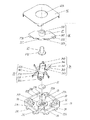
図1は本発明の一実施の形態による多方向スライドスイッチのカバーを除いた平面図、図2は正面断面図、図3は分解斜視図、図4はケースの平面図である。
【0027】
同図において、21は樹脂で形成された箱形のケースで、図3および図4に示すように、四角形の底面21Aの外周四辺から直立する四つの側壁22A〜22Dの内側面上には、底面21Aの中心に対し点対称位置にそれぞれ平板状の固定接点23A〜23Dが露出状態で配設され、各固定接点23A〜23Dと導通した端子24A〜24Dは各側壁22A〜22Dの外周から突出している。
【0028】
また、上記底面21Aにおいて、上記二つずつの固定接点23Aと23Bおよび23Cと23Dの中間を通る一方の対角線上には、上面視台形の支持部25および26が突出しており、側壁22A〜22Dのコーナー部21Bおよび21Cと対向する側の側面には接続接点27および28が設けられて、各接続接点27および28と導通した端子27Aおよび28Aも側壁22Aおよび22Cの外周から突出している。
【0029】
なお、これらの固定接点23A〜23Dと接続接点27,28および、導通した端子24A〜24Dと27A,28Aはスライドスイッチ部用のものである。
【0030】
一方、ケース21の底面21A中央部を囲む円形壁部21D内には、中心接点29とこれを挟む一対の側部接点30からなる押圧スイッチ部用の固定接点が設けられ、それぞれと導通した端子29Aと30Aも側壁22Bと22Dの外周から突出している。
【0031】
そして、この押圧スイッチ部用の固定接点に対し、図2に示すように、弾性金属薄板を椀状に絞り加工したドーム状可動接点31が、外周下端部が側部接点30上に載って頂部下面が中心接点29と所定の間隔をあけて対峙するように配設されて、押圧スイッチ部が構成されている。
【0032】
また、ケース21底面21Aの他方のコーナー部には、ガイド部32および33が設けられている。
【0033】
このガイド部32および33は、対向する壁部22A,22Cどうし、および22B,22Dどうしとそれぞれ平行な方向の窪みを十字状に設けて構成されている。
【0034】
なお、ガイド部の構成は、上記のようにケース21底面21Aを十字状に窪ませて構成するものに限らず、ケース壁部22A,22Cおよび22B,22Dに突部を設け、少なくとも上記十字状の外方側が構成されてあるものであればよい。
【0035】
次に、34および35は所定巾の弾性金属薄板を、図3に示すような略M字形状に折り曲げ形成された可動接点で、図1に示すように、M字形中心部の接続脚部34Aおよび35Aが、ケース21の支持部25の接続接点27とコーナー部21Bの間、および支持部26の接続接点28とコーナー部21Cの間にそれぞれ圧入・固定されて、接続接点27および28と導通している。
【0036】
そして、各可動接点34および35のM字形両端の弾性脚34B,34Cおよび35B,35Cの先端部34D,34Eおよび35D,35Eが、ケース21の側壁22A,22B上の固定接点23A,23Bの近傍および側壁22C,22D上の固定接点23C,23Dの近傍に、各固定接点と所定の間隔をあけて弾接している。
【0037】
また、可動接点34および35の中心部と二つの弾性脚34B,34Cおよび35B,35Cの根元部とを連結する二つずつの弾性アーム34F,34Gおよび35F,35Gは、図1に示すように、それぞれの中間部が支持部25および26の対称位置にある角部25A,25Bおよび26A,26Bに弾接して、ケース21のコーナー部21Bと21Cを結ぶ対角線に対し対称位置にあるように支持されて位置規制されている。
【0038】
そして、36は樹脂形成された駆動体で、図1に点線で示すように、長板状の本体部36A両端の、中心に対し対称な突出部の下面にそれぞれ設けられた柱状部37Aおよび37Bがケース21の対向する壁部22A,22Cおよび22B,22Dと平行な方向に所定量だけ直線移動可能なように、ケース21底面21Aの十字状のガイド部32および33の中心部に位置すると共に、本体部36A下面に突出した方形部38の四つの側面当接部38A〜38Dが、それぞれ可動接点34および35の各弾性アーム34F,34Gおよび35F,35Gの先端である各弾性脚との連結部近傍に当接することによって中立位置を保つようにケース21内に収容されている。
【0039】
なお、この駆動体36に設けた柱状部37Aおよび37Bが、駆動体36の規制部として機能するものである。
【0040】
また、図2および図3に示すように、駆動体36本体部36Aの上面中央には操作レバー39が一体に設けられて、ケース21の上面開口部を塞ぐようにケース21に結合されたカバー40の中央の孔40Aから外方に突出している。
【0041】
更に、操作レバー39中心の貫通孔39Aには、押圧スイッチ駆動用の押圧棒41が上下動可能に配設されて、その下端突部41Aは上記押圧スイッチ部のドーム状可動接点31の頂部上面に当接している。
【0042】
なお、後で詳述するが、押圧棒41の下端には、大径のフランジ部41Bが設けられており、このフランジ部41B下面に下端突部41Aが設けられている。
【0043】
本実施の形態による多方向スライドスイッチは以上のように構成されるものであり、次にその動作について説明する。
【0044】
まず、スライドスイッチ部の動作について説明すると、図1に示す非操作状態において、スライドスイッチ部の可動接点34および35の弾性脚の先端部は何れも固定接点23A〜23Dと接触しないOFF状態にある。
【0045】
この状態から、図5のスライド操作時においてカバーを除いた状態の平面図に矢印で示すように、操作レバー39に押し力を加えて右方向へスライド操作すると、駆動体36の本体部36Aの突出部下面に設けられた二つの柱状部37A,37Bが、ケース21底面21Aの十字状のガイド部32,33内の右側の窪み位置に、同図に小さな矢印で示すように案内されて、駆動体36全体として右方向へ動き、本体部36A下面の方形部38の側面当接部38Cは可動接点35の弾性アーム35Fから離れ、側面当接部38Bおよび38Dは、それぞれ可動接点34の弾性アーム34Gの弾性脚34Cとの連結部近傍および可動接点35の弾性アーム35Gの弾性脚35Cとの連結部近傍に当接したまま右方向へ動く。
【0046】
そして、駆動体36本体部36A下面の方形部38の側面当接部38Aが、当接している可動接点34の弾性アーム34Fの先端を右方向へ押し、押された弾性アーム34Fはその根元の固定部である接続脚部34A部分を中心として回動して、その中間部がケース21の支持部25の角部25Aから離れると共に、弾性脚34Bの根元部がケース21の側壁22Aに近づくことにより、その先端部34Dが側壁22Aの内側面上を弾接・摺動して固定接点23Aに接触する。
【0047】
これにより、接続接点27と固定接点23Aの間すなわち端子27Aと24Aの間が可動接点34を介して導通され、その信号が外部へ伝達される。
【0048】
この時、可動接点34の弾性アーム34Gおよび可動接点35の弾性アーム35F,35Gは、それぞれケース21の支持部25の角部25Bおよび支持部26の角部26A,26Bに弾接していて動かない。
【0049】
この後、操作レバー39に加える押し力を除くと、可動接点34の弾性復元力により、弾性アーム34Fが駆動体36の方形部38の側面当接部38Aをケース21の中心方向へ押すことによって、駆動体36の二つの柱状部37A,37Bがガイド部32,33に案内されながら、元の図1の非操作状態、すなわち駆動体36が、再び可動接点34と35とで外周の四方向から中央側に向かって付勢されている安定した中立状態に復帰し、可動接点34の弾性脚34Bの先端部34Dは固定接点23Aから離れる。
【0050】
同様に、図1に示す非操作状態において、操作レバー39を左方向または後ろあるいは手前方向へ押すことによって、接続接点28と固定接点23Cの間、または接続接点27と固定接点23Bあるいは接続接点28と固定接点23Dの間を接離することができる。
【0051】
このように、本実施の形態によるものは、簡素な構成の駆動体36の規制部となる柱状部37A,37Bをガイド部32,33で移動規制することにより、スライド操作方向を、左右および後ろあるいは手前方向の四方向のみに規制せしめたものであり、かつ当該操作方向のいずれかに操作した際に所定信号が得られる接点配置としてあるものである。
【0052】
また、本実施の形態によるものは、構成部材数も少ないので組み立ても容易であり、高さ寸法の低いものとなる。
【0053】
なお、以上の説明において、可動接点34および35は弾性金属薄板を略M字形状に折り曲げ加工したもので、固定部となったM字形中心部を通る中心線に対して対称に、弾性アーム34F,34Gと弾性脚34B,34Cおよび弾性アーム35F,35Gと弾性脚35B,35Cが一体に形成されているとしたが、これをM字形中心部で二つに分割して、分割した部分それぞれをケース21のコーナー部21Bおよび21Cに固定してもよいものである。
【0054】
このようにすることによって、各固定接点23A〜23Dをそれぞれ電気的に独立したスイッチとすることができる。
【0055】
また、以上の説明においては、操作レバー39に横方向の押し力を加えてスライド操作する際に、スライドスイッチ部の略M字形状の可動接点34および35の弾性脚の先端部34D,34Eおよび35D,35Eは、それぞれのM字形中心部に近づく方向にケース21の側壁22A〜22Dの内側面上を弾接・摺動するとしたが、これをM字形中心部から離れる方向に動くように、各弾性脚34B,34Cおよび35B,35Cの向きを変えてもよい。
【0056】
そして、スライドスイッチ部は非操作状態においてOFF状態にあり、スライド操作することによって所定の端子間が導通するとしたが、これを非操作状態において導通状態にあり、スライド操作することによって所定の端子間がOFF状態となるようにすることもできる。
【0057】
更に、固定接点23A〜23Dはケース21の底面21Aの外周四辺から直立する側壁22A〜22Dの内側面上に配設されるとしたが、これを側壁22A〜22D近くの底面21A上に設けて、可動接点34および35の弾性脚34B,34Cおよび35B,35Cの先端が、底面21Aの当該固定接点と接離する構成としてもよい。
【0058】
次に、押圧スイッチ部の動作について説明すると、図2に示す非操作状態において、押圧スイッチ部はOFF状態すなわち図4に示す接続端子29Aと30Aの間は導通していない。
【0059】
この状態から、図6の押圧操作時の正面断面図に矢印で示すように、操作レバー39中心に配設された押圧棒41に下方への押し力を加えて押圧操作すると、押圧棒41の下端突部41Aが当接するドーム状可動接点31の頂部を下方に押して弾性変形させて、頂部下面を中心接点29に接触させる。
【0060】
これにより、中心接点29と側部接点30の間すなわち端子29Aと30A(図4参照)の間はドーム状可動接点31を介して導通され、その信号が外部へ伝達される。
【0061】
この後、押圧棒41に加える押し力を除くと、ドーム状可動接点31の弾性復元力により押圧棒41は上方へ押し戻されて元の図2の状態に復帰し、ドーム状可動接点31の頂部下面は中心接点29から離れる。
【0062】
なお、この押圧スイッチ部は、駆動体36が非操作状態の位置にある場合のみに動作するように構成されており、次にその内容について説明する。
【0063】
図2および図3に示すように、押圧棒41の下端部には大径のフランジ部41Bが設けられて、その中心に下端突部41Aが突出形成されている。
【0064】
そして、このフランジ部41Bは、図2に示すように、ケース21の底面21Aに押圧スイッチ部を囲むように設けられた円形壁部21Dの上端よりも、押圧スイッチ部の動作ストロークよりも小さい寸法だけ上方に位置し、また、フランジ部41Bの外径は、ケース21の円形壁部21Dの内周に対してスライド操作時の操作レバー39すなわち押圧棒41の移動量よりも小さい隙間を有する径となっている。
【0065】
従って、図7のカバーおよび駆動体を除いた平面図に二点鎖線で示すように、操作レバー39をスライド操作する時に、操作レバー39と共に押圧棒41が横方向へ移動すると、フランジ部41Bの一部がケース21の円形壁部21Dの上端に重なることになり、この状態において押圧棒41はフランジ部41Bと円形壁部21D上端との高さの差分だけしか下方へ動くことができない。
【0066】
すなわち、操作レバー39をスライド操作した状態においては、押圧スイッチ部が動作しない構成にできるものである。
【0067】
なお、このフランジ部41Bは押圧棒41が操作レバー39の貫通孔39Aから抜けないようにする役目もしている。
【0068】
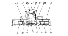
以上の説明において、多方向スライドスイッチの操作レバー部にツマミを装着しない状態について説明したが、図8はツマミを装着した状態の一事例の正面断面図である。
【0069】
同図において、操作レバー39の先端部には操作用のツマミ42が被せられ、その中心の貫通孔42A内には押ボタン43が独立して上下動可能に挿入されている。
【0070】
そして、ツマミ42の下端は大径部42Bとなり、その外周下端はケース21の上面開口部を覆うカバー40の孔40Aの外方平面部に当接している。
【0071】
このような構成のツマミ42とすることにより、ツマミ42に横方向の押し力を加えてスライド操作する際に、駆動体36の傾きによるヒッカカリ等が生じ難く、スムーズに操作することができると共に、カバー40の孔40Aを塞いで外観を良くして、防塵性を高めることができ、更に、押ボタン43を押圧操作して押圧スイッチ部を動作させることができるものである。
【0072】
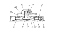
また、図9は、以上に説明した多方向スライドスイッチの駆動体36の構成を変えたものの正面断面図である。
【0073】
同図に示すように、駆動体44の中央孔44Aに対して操作レバー45が独立して上下動可能に係合され、その下端突部45Aが押圧スイッチ部のドーム状可動接点31の頂部上面に当接している。
【0074】
そして、操作レバー45の先端部に被せられたツマミ46は、その下面とカバー40の間に押圧スイッチ部の動作ストロークよりも少し大きい隙間が設けられている。
【0075】
このような構成とすることによって、一つのツマミ46に横方向への押し力を加えスライド操作してスライドスイッチ部を、下方への押し力を加え押圧操作して押圧スイッチ部を、それぞれ動作させることができるので、操作レバー45およびツマミ46の形状が簡単で、構成部材数を少なくできるものである。
【0076】
【発明の効果】
以上のように本発明によれば、操作レバーをスライド操作してケース内に収容した駆動体を所定の方向へ移動させた際に、この駆動体の移動に伴って駆動体で所定の可動接点を押圧して弾接摺動させ固定接点に接離させる構成としたので、構成部材数が少なくて組み立ても容易であると共に、高さ寸法が小さい多方向スライドスイッチを実現できるという有利な効果が得られる。
さらに、ケース内底面の中央に押圧スイッチ部を配設して、操作レバーを貫通して上下動可能に配設された押圧棒を押し下げることにより押圧スイッチ部を動作させ、ケース底面の中央に押圧スイッチ部を囲む壁部を設けると共に、非操作状態において壁部の上端よりも所定寸法だけ上方に位置し、壁部の内周に対し、スライド操作時の駆動体の移動量よりも小さい寸法の隙間を有する大径部を押圧棒の下端に設けた構成としたので、操作レバーをスライド操作して得られる信号に加えて、押圧棒を押し下げることにより別の信号が得られ、さらに、非操作状態においては押圧棒を押し下げて押圧スイッチ部を動作させることができるが、操作レバーのスライド操作時に駆動体と共に押圧棒が移動すると、押圧棒の大径部が部分的に壁部上に移動して押圧棒を押し下げることができないものにでき、スライド操作時における押圧スイッチ部の誤動作が起こり難い多方向スライドスイッチを実現できるという有利な効果も得られる。
【図面の簡単な説明】
【図1】本発明の一実施の形態による多方向スライドスイッチのカバーを除いた平面図
【図2】同正面断面図
【図3】同分解斜視図
【図4】同要部であるケースの平面図
【図5】同スライド操作時におけるカバーを除いた平面図
【図6】同押圧操作時の正面断面図
【図7】同カバーおよび駆動体を除いた平面図
【図8】同ツマミを装着した状態の正面断面図
【図9】同他の構成の多方向スライドスイッチの正面断面図
【図10】従来の多方向スライドスイッチの正面断面図
【図11】同分解斜視図
【図12】同要部であるケースの平面図
【図13】同要部である第一スライド部材の組立て状態を説明する一部断面の平面図
【図14】同要部である第二スライド部材の組立て状態を説明する一部断面の平面図
【図15】同操作レバーをX軸方向へスライド操作時の状態を説明する平面図
【図16】同操作レバーをY軸方向へスライド操作時の状態を説明する平面図
【符号の説明】
21 ケース
21A 底面
21B,21C コーナー部
21D 円形壁部
22A〜22D 側壁
23A〜23D 固定接点
24A〜24D,27A,28A,29A,30A 端子
25,26 支持部
25A,25B,26A,26B 角部
27,28 接続接点
29 中心接点
30 側部接点
31 ドーム状可動接点
32,33 ガイド部
34,35 可動接点
34A,35A 接続脚部
34B,34C,35B,35C 弾性脚
34D,34E,35D,35E 先端部
34F,34G,35F,35G 弾性アーム
36,44 駆動体
36A 本体部
37A,37B 柱状部
38 方形部
38A〜38D 側面当接部
39,45 操作レバー
39A,42A 貫通孔
40 カバー
40A 孔
41 押圧棒
41A,45A 下端突部
41B フランジ部
42,46 ツマミ
42B 大径部
43 押ボタン
44A 中央孔[0001]
BACKGROUND OF THE INVENTION
The present invention relates to a multi-directional slide switch that is used for input operations of various electronic devices and performs a scroll operation of double-sided display contents by a slide operation of an operation lever.
[0002]
[Prior art]
The content of this type of conventional slide switch will be described with reference to FIGS.
[0003]
10 is a front cross-sectional view of a conventional multi-directional slide switch, FIG. 11 is an exploded perspective view, FIG. 12 is a plan view of the case, and FIG. 13 is a partial cross-sectional plan view illustrating the assembled state of the first slide member. 14 is a plan view of a partial cross section for explaining the assembled state of the second slide member.
[0004]
As shown in FIGS. 10 to 12, a box-
[0005]
An
[0006]
Further, as shown in FIGS. 11, 13, and 14, the portion that guides the
[0007]
A pair of
[0008]
Further, at this time, the tip ends of the four elastic legs 7A to 7D of the
[0009]
In addition, 10 provided in the center of the inner bottom surface of the
[0010]
When the conventional multi-directional slide switch configured as described above is slid in the X-axis direction by pressing the
[0011]
Thereafter, when the pressing force applied to the
[0012]
Similarly, in the non-operating state shown in FIG. 14, when the
[0013]
As prior art document information related to the invention of this application, for example,
[0014]
[Patent Document 1]
JP 2001-307599 A
[0015]
[Problems to be solved by the invention]
However, the conventional multi-directional slide switch has a large number of constituent members and takes a lot of time to assemble, which is expensive and has a large height dimension for overlapping the
[0016]
The present invention solves such a conventional problem, and an object thereof is to provide a multi-directional slide switch having a small number of components and being easily assembled and having a small height dimension.
[0017]
[Means for Solving the Problems]
In order to achieve the above object, the present invention has the following configuration.
[0018]
According to the first aspect of the present invention, there is provided a box-shaped case in which fixed contacts are arranged on each of the inner side surface of the side wall standing upright from the outer peripheral four sides of the rectangular bottom surface or the bottom surface in the vicinity thereof; A movable contact arranged in the case so that one end side of the elastic arm whose movement is restricted is in contact with or away from any of the fixed contacts, and a main body portion provided with an operation lever protruding upward, In the non-operating state, the main body is urged by the elastic arm of each movable contact and is positioned at the center position of the case in a non-operating state.BecomeWhen the drive body is slid through the operation lever, one of the movable contacts arranged on the movement direction side of the drive body is pushed by the drive body main body portion as the drive body moves. Contact one of the corresponding fixed contactsAnd a multi-directional slide switch that operates the press switch part by disposing a press switch part that is disposed in the center of the bottom surface of the case and penetrates an operation lever so as to be movable up and down. In addition, a wall portion that surrounds the pressing switch portion is provided at the center of the bottom surface of the case and is positioned above the upper end of the wall portion by a predetermined dimension in a non-operating state, It is a multi-directional slide switch in which a large diameter part with a gap smaller than the amount of movement is provided at the lower end of the pressing rod.The number of components is small and assembly is easy, and the height dimensionIn addition to the signal obtained by sliding the operation lever, another signal can be obtained by depressing the pressure bar. Further, in a non-operation state, the pressure bar is depressed to operate the pressure switch unit. However, if the pressing rod moves with the driver during the sliding operation of the operating lever, the large diameter part of the pressing rod can partially move on the wall and the pressing rod cannot be pushed down. Operation of the push switch is unlikely to occurThis has the effect of realizing a multidirectional slide switch.
[0019]
The invention according to claim 2 is the invention according to
[0020]
According to a third aspect of the present invention, in the first aspect of the present invention, on the inner side surface of the side wall that stands upright from the outer peripheral four sides of the quadrangular bottom surface or on the bottom surface in the vicinity thereof, the point is symmetrical with respect to the center of the bottom surface. Each box-shaped case having a fixed contact and an elastic metal thin plate having a predetermined width are formed in a substantially M-shape, and the center of the M-shape is fixed on one diagonal line on the bottom surface of the case. The elastic leg tips elastically contact two inner surfaces that are line symmetrical with respect to one diagonal of the side walls, and connect the M-shaped central part and the base parts of the two elastic legs. The arm is supported from the inside so that it is in a line-symmetrical position with respect to one of the diagonal lines, and two movable contacts respectively disposed in line-symmetrical positions with respect to the other diagonal line on the bottom surface of the case, The guide part Both ends of the main body are regulated to move linearly by a predetermined amount in directions parallel to the two opposing side walls, and in the non-operating state, the four abutting portions of the main body are each of the two movable contacts. A drive having an operating lever that protrudes outward from the upper surface opening of the case while being accommodated in the case so that it is in the center position of the case by contacting the vicinity of the connecting portion between the elastic arms and the elastic legs. This is a multi-directional slide switch consisting of a body. When the operating lever is pressed in parallel with the bottom of the case and slid in any of the four directions parallel to the two opposing side walls of the case, the entire drive body is The tip of the elastic leg is elastically contacted by the contact part of the drive body that moves linearly along the guide part and presses the vicinity of the connecting part of the elastic arm of the movable contact that is in contact with the moving part. Case Separated contact with the fixed contacts corresponding slides on the inner surface of the side wall has the effect that those predetermined signal is obtained can be realized.
[0022]
Claim4The invention described in claim1In the described invention, the upper surface opening of the case is closed with a flat cover, the operation lever is protruded from the hole provided in the center thereof, and the outer peripheral lower end of the knob attached to the operation lever is placed outward of the hole of the cover. The pressing bar can be pushed down from a through hole provided in the center of the knob while being abutted.1In addition to the effects of the described invention, when the operation lever is slid through the knob, it is unlikely to cause a crack or the like due to the tilt of the drive body, and can be operated smoothly, and the cover hole is closed to enhance the appearance. It has the effect that it can improve and improve dustproofness.
[0023]
Claim5The invention described in claim1In the described invention, the operating lever is engaged with the main body of the driving body independently so as to move up and down, and also serves as a pressing rod. The operating lever can be slid, and the operating lever can be pushed down to press the switch. There is an effect that a multi-directional slide switch with few components can be realized.
[0025]
DETAILED DESCRIPTION OF THE INVENTION
Hereinafter, an embodiment of the present invention will be described with reference to FIGS.
[0026]
(Embodiment)
FIG. 1 is a plan view excluding a cover of a multi-directional slide switch according to an embodiment of the present invention, FIG. 2 is a front sectional view, FIG. 3 is an exploded perspective view, and FIG.
[0027]
In the same figure, 21 is a box-shaped case made of resin, and as shown in FIGS. 3 and 4, on the inner side surfaces of the four
[0028]
In addition, on the
[0029]
The fixed
[0030]
On the other hand, in the circular wall portion 21D surrounding the central portion of the
[0031]
Then, as shown in FIG. 2, a dome-shaped
[0032]
In addition,
[0033]
The
[0034]
The configuration of the guide portion is not limited to the configuration in which the
[0035]
Next, 34 and 35 are movable contacts formed by bending an elastic metal thin plate having a predetermined width into a substantially M shape as shown in FIG. 3, and as shown in FIG. 1, a connecting
[0036]
The
[0037]
Further, as shown in FIG. 1, two
[0038]
[0039]
Note that the columnar portions 37 </ b> A and 37 </ b> B provided on the
[0040]
As shown in FIGS. 2 and 3, an operating
[0041]
Further, a
[0042]
As will be described in detail later, a large-
[0043]
The multi-directional slide switch according to the present embodiment is configured as described above, and the operation thereof will be described next.
[0044]
First, the operation of the slide switch unit will be described. In the non-operation state shown in FIG. 1, the tip ends of the elastic legs of the
[0045]
From this state, as shown by the arrow in the plan view of the state where the cover is removed during the sliding operation of FIG. The two
[0046]
Then, the
[0047]
Thus, the connection between the
[0048]
At this time, the
[0049]
Thereafter, when the pushing force applied to the
[0050]
Similarly, in the non-operating state shown in FIG. 1, the
[0051]
As described above, according to the present embodiment, by restricting the movement of the
[0052]
In addition, according to the present embodiment, since the number of constituent members is small, assembly is easy, and the height dimension is low.
[0053]
In the above description, the
[0054]
By doing in this way, each
[0055]
Further, in the above description, when a sliding operation is performed by applying a lateral pressing force to the
[0056]
The slide switch portion is in the OFF state in the non-operating state, and the predetermined terminals are electrically connected by the sliding operation. However, this is in the conductive state in the non-operating state, and the predetermined terminals are connected by the sliding operation. Can be in an OFF state.
[0057]
Further, the fixed
[0058]
Next, the operation of the pressing switch unit will be described. In the non-operation state shown in FIG. 2, the pressing switch unit is in an OFF state, that is, the
[0059]
From this state, as shown by the arrow in the front cross-sectional view during the pressing operation in FIG. 6, when a pressing operation is performed by applying a downward pressing force to the
[0060]
Thereby, the
[0061]
Thereafter, when the pressing force applied to the
[0062]
The push switch unit is configured to operate only when the driving
[0063]
As shown in FIGS. 2 and 3, a large-
[0064]
And this
[0065]
Therefore, as shown by a two-dot chain line in the plan view excluding the cover and the driving body in FIG. 7, when the operating
[0066]
That is, in a state where the
[0067]
The
[0068]
In the above description, the state in which the knob is not attached to the operation lever portion of the multidirectional slide switch has been described. FIG. 8 is a front sectional view of an example of the state in which the knob is attached.
[0069]
In the drawing, an operation knob 42 is put on the tip of the
[0070]
The lower end of the knob 42 is a large-
[0071]
With the knob 42 having such a configuration, when a sliding operation is performed by applying a pressing force in the lateral direction to the knob 42, it is difficult to cause a crack or the like due to the inclination of the driving
[0072]
FIG. 9 is a front cross-sectional view of the multi-directional slide
[0073]
As shown in the figure, the
[0074]
And the
[0075]
By adopting such a configuration, the slide switch unit is operated by applying a lateral pressing force to one
[0076]
【The invention's effect】
As described above, according to the present invention, when the driving body housed in the case is moved in a predetermined direction by sliding the operation lever, the driving body moves with the predetermined movable contact point as the driving body moves. Since it is configured to be pressed and slid to contact and separate from the fixed contact, the number of components is small, assembly is easy, and a multi-directional slide switch with a small height can be realized. can get.
In addition, a push switch part is arranged at the center of the bottom surface of the case, and the push switch part is operated by pushing down a push rod that can be moved up and down through the operation lever. In addition to providing a wall portion surrounding the switch portion, it is positioned above the upper end of the wall portion by a predetermined dimension in a non-operating state, and has a dimension smaller than the moving amount of the driving body during the slide operation with respect to the inner periphery of the wall portion. Since the large diameter part with a gap is provided at the lower end of the pressing rod, in addition to the signal obtained by sliding the operation lever, another signal can be obtained by pressing down the pressing rod, and further non-operation In the state, the push rod can be pushed down to operate the push switch, but when the push rod moves together with the drive body during the sliding operation of the operation lever, the large diameter portion of the push rod partially on the wall Dynamic and can to those unable to push down the pressing rod, also obtained advantageous effect can be realized it is difficult to occur multi-directional slide switch malfunction push switch portion during the sliding operation.
[Brief description of the drawings]
FIG. 1 is a plan view of a multidirectional slide switch according to an embodiment of the present invention with a cover removed.
FIG. 2 is a front sectional view of the same.
FIG. 3 is an exploded perspective view of the same.
FIG. 4 is a plan view of a case which is the main part of the same.
FIG. 5 is a plan view with the cover removed during the sliding operation.
FIG. 6 is a front sectional view at the time of the pressing operation.
FIG. 7 is a plan view excluding the cover and the driving body.
FIG. 8 is a front sectional view of the state where the knob is mounted.
FIG. 9 is a front sectional view of a multi-directional slide switch having another configuration.
FIG. 10 is a front sectional view of a conventional multi-directional slide switch.
FIG. 11 is an exploded perspective view of the same.
FIG. 12 is a plan view of the case as the main part
FIG. 13 is a partial cross-sectional plan view illustrating the assembled state of the first slide member which is the main part
FIG. 14 is a partial cross-sectional plan view illustrating the assembled state of the second slide member which is the main part
FIG. 15 is a plan view illustrating a state when the operation lever is slid in the X-axis direction.
FIG. 16 is a plan view illustrating a state when the operation lever is slid in the Y-axis direction.
[Explanation of symbols]
21 cases
21A Bottom
21B, 21C Corner
21D circular wall
22A-22D side wall
23A-23D fixed contact
24A-24D, 27A, 28A, 29A, 30A terminals
25, 26 support part
25A, 25B, 26A, 26B Corner
27, 28 Connection contact
29 Center contact
30 Side contact
31 Dome-shaped movable contact
32, 33 Guide part
34, 35 Movable contact
34A, 35A Connecting leg
34B, 34C, 35B, 35C Elastic leg
34D, 34E, 35D, 35E Tip
34F, 34G, 35F, 35G Elastic arm
36, 44 Driver
36A body
37A, 37B Columnar part
38 Square part
38A-38D Side contact part
39, 45 Operation lever
39A, 42A Through hole
40 cover
40A hole
41 Press rod
41A, 45A Lower end protrusion
41B Flange
42, 46 knob
42B Large diameter part
43 pushbutton
44A center hole
Claims (5)
Priority Applications (3)
| Application Number | Priority Date | Filing Date | Title |
|---|---|---|---|
| JP2002336423A JP4089397B2 (en) | 2002-11-20 | 2002-11-20 | Multi-directional slide switch |
| US10/693,964 US6906269B2 (en) | 2002-11-20 | 2003-10-28 | Multi-directional slide switch |
| CNB2003101161892A CN1267945C (en) | 2002-11-20 | 2003-11-19 | Multi-direction slide switch |
Applications Claiming Priority (1)
| Application Number | Priority Date | Filing Date | Title |
|---|---|---|---|
| JP2002336423A JP4089397B2 (en) | 2002-11-20 | 2002-11-20 | Multi-directional slide switch |
Publications (2)
| Publication Number | Publication Date |
|---|---|
| JP2004171924A JP2004171924A (en) | 2004-06-17 |
| JP4089397B2 true JP4089397B2 (en) | 2008-05-28 |
Family
ID=32700269
Family Applications (1)
| Application Number | Title | Priority Date | Filing Date |
|---|---|---|---|
| JP2002336423A Expired - Fee Related JP4089397B2 (en) | 2002-11-20 | 2002-11-20 | Multi-directional slide switch |
Country Status (3)
| Country | Link |
|---|---|
| US (1) | US6906269B2 (en) |
| JP (1) | JP4089397B2 (en) |
| CN (1) | CN1267945C (en) |
Families Citing this family (17)
| Publication number | Priority date | Publication date | Assignee | Title |
|---|---|---|---|---|
| FR2844094B1 (en) * | 2002-08-28 | 2005-11-18 | Itt Mfg Enterprises Inc | MULTIPLE SWITCHING DEVICE |
| JP4619196B2 (en) * | 2005-05-23 | 2011-01-26 | 帝国通信工業株式会社 | Sliding electronic parts with pressure switch |
| US7250579B2 (en) * | 2005-09-21 | 2007-07-31 | Micro Pneumatic Logic, Inc. | Large actuation area switching device |
| US20070068785A1 (en) * | 2005-09-26 | 2007-03-29 | Taiwan Pwl Corporation | Rocker level assembly |
| JP4721874B2 (en) * | 2005-11-02 | 2011-07-13 | ホシデン株式会社 | Slide operation switch |
| JP4674167B2 (en) * | 2006-01-25 | 2011-04-20 | ホシデン株式会社 | Slide operation switch |
| CN201000845Y (en) * | 2006-07-14 | 2008-01-02 | 富士康(昆山)电脑接插件有限公司 | Polydirectional switch |
| EP2047357A1 (en) | 2006-07-19 | 2009-04-15 | Koninklijke Philips Electronics N.V. | Apparatus with multidirectional key for cursor control |
| JP2009544134A (en) | 2006-07-19 | 2009-12-10 | コーニンクレッカ フィリップス エレクトロニクス エヌ ヴィ | Simple multi-directional keys for cursor control |
| KR100810314B1 (en) * | 2006-10-11 | 2008-03-04 | 삼성전자주식회사 | Key input device of mobile terminal |
| WO2009002039A2 (en) | 2007-06-22 | 2008-12-31 | Youn Soo Kim | Button for electric product |
| BRPI1007217A2 (en) | 2009-01-21 | 2016-02-23 | Omron Dualtec Automotive Electronics Inc | electric seat switch to prevent simultaneous activation |
| JP5446844B2 (en) * | 2009-12-24 | 2014-03-19 | ソニー株式会社 | Information processing apparatus and switch apparatus |
| CN102468078B (en) * | 2010-11-05 | 2014-09-24 | 富士康(昆山)电脑接插件有限公司 | multi-directional switching device |
| JP6048830B2 (en) * | 2013-10-09 | 2016-12-21 | アルプス電気株式会社 | Haptic multi-directional input device |
| CN114008558B (en) * | 2019-06-19 | 2023-03-24 | 阿尔卑斯阿尔派株式会社 | Multi-directional input device |
| CN111668057B (en) * | 2020-06-29 | 2025-02-28 | 深圳市致尚科技股份有限公司 | Multi-directional input device, handle and game console |
Family Cites Families (10)
| Publication number | Priority date | Publication date | Assignee | Title |
|---|---|---|---|---|
| JPS58328U (en) * | 1981-05-26 | 1983-01-05 | 株式会社東海理化電機製作所 | multi-directional switch |
| US4525607A (en) * | 1983-02-04 | 1985-06-25 | Yasutaka Senoh | Simplified electric switch construction |
| US5153401A (en) * | 1991-10-08 | 1992-10-06 | Tseng Tien Fu | Sliding block electrical switch |
| US5327162A (en) * | 1992-03-17 | 1994-07-05 | Alps Electric Co., Ltd. | X-y direction input device |
| JP3673339B2 (en) * | 1996-09-30 | 2005-07-20 | アルプス電気株式会社 | Switch device |
| US5735391A (en) * | 1996-12-20 | 1998-04-07 | United Technologies Automotive, Inc. | Dual slide three-position switch |
| JP2001307599A (en) | 2000-02-15 | 2001-11-02 | Alps Electric Co Ltd | Multidirectional slide switch |
| JP3991577B2 (en) * | 2000-11-07 | 2007-10-17 | 松下電器産業株式会社 | Lever switch |
| JP2003059374A (en) * | 2001-06-04 | 2003-02-28 | Mic Electron Co | Slide switch |
| US6689967B2 (en) * | 2002-03-11 | 2004-02-10 | Mitsuku Denshi Kogyo K.K. | Slide switch |
-
2002
- 2002-11-20 JP JP2002336423A patent/JP4089397B2/en not_active Expired - Fee Related
-
2003
- 2003-10-28 US US10/693,964 patent/US6906269B2/en not_active Expired - Lifetime
- 2003-11-19 CN CNB2003101161892A patent/CN1267945C/en not_active Expired - Fee Related
Also Published As
| Publication number | Publication date |
|---|---|
| CN1503292A (en) | 2004-06-09 |
| JP2004171924A (en) | 2004-06-17 |
| US6906269B2 (en) | 2005-06-14 |
| CN1267945C (en) | 2006-08-02 |
| US20050000783A1 (en) | 2005-01-06 |
Similar Documents
| Publication | Publication Date | Title |
|---|---|---|
| JP4089397B2 (en) | Multi-directional slide switch | |
| CN100454460C (en) | Multi-operation electronic components | |
| JP2003338231A (en) | Push-on switch | |
| KR20070078058A (en) | Slide Operated Switch | |
| JP5146588B2 (en) | Push-button switch | |
| JP3766252B2 (en) | Switch device | |
| KR101435685B1 (en) | Combined-operation type input device | |
| US20020023827A1 (en) | Multi-directional switch and apparatus using the same | |
| JP4730171B2 (en) | Push / Slide switch | |
| JPH10302576A (en) | Control switch | |
| JP5551578B2 (en) | Multi-directional switch device | |
| CN114141564A (en) | Push-button switch | |
| JP4375381B2 (en) | Multi-directional input device and electronic apparatus equipped with the same | |
| JPH0528666Y2 (en) | ||
| JP2014013709A (en) | Composite switch | |
| JPH084655Y2 (en) | Structure of button operation part of electronic equipment | |
| JPH069396Y2 (en) | Push-button switch | |
| JP2005209565A (en) | Push-button switch | |
| JP4364037B2 (en) | Operation panel for electronic parts | |
| JP3437814B2 (en) | Movable contact piece for switch | |
| JPH0636651A (en) | Pushbutton switch | |
| JP2004021790A (en) | Multidirectional input device | |
| JPH0336016Y2 (en) | ||
| JP3788764B2 (en) | Sliding electronic parts with pressure switch | |
| JP2001325857A (en) | Multi-directional input device |
Legal Events
| Date | Code | Title | Description |
|---|---|---|---|
| A621 | Written request for application examination |
Free format text: JAPANESE INTERMEDIATE CODE: A621 Effective date: 20050315 |
|
| RD01 | Notification of change of attorney |
Free format text: JAPANESE INTERMEDIATE CODE: A7421 Effective date: 20050707 |
|
| A977 | Report on retrieval |
Free format text: JAPANESE INTERMEDIATE CODE: A971007 Effective date: 20070921 |
|
| A131 | Notification of reasons for refusal |
Free format text: JAPANESE INTERMEDIATE CODE: A131 Effective date: 20071016 |
|
| A521 | Written amendment |
Free format text: JAPANESE INTERMEDIATE CODE: A523 Effective date: 20071217 |
|
| TRDD | Decision of grant or rejection written | ||
| A01 | Written decision to grant a patent or to grant a registration (utility model) |
Free format text: JAPANESE INTERMEDIATE CODE: A01 Effective date: 20080205 |
|
| A61 | First payment of annual fees (during grant procedure) |
Free format text: JAPANESE INTERMEDIATE CODE: A61 Effective date: 20080218 |
|
| FPAY | Renewal fee payment (event date is renewal date of database) |
Free format text: PAYMENT UNTIL: 20110307 Year of fee payment: 3 |
|
| FPAY | Renewal fee payment (event date is renewal date of database) |
Free format text: PAYMENT UNTIL: 20110307 Year of fee payment: 3 |
|
| FPAY | Renewal fee payment (event date is renewal date of database) |
Free format text: PAYMENT UNTIL: 20120307 Year of fee payment: 4 |
|
| FPAY | Renewal fee payment (event date is renewal date of database) |
Free format text: PAYMENT UNTIL: 20130307 Year of fee payment: 5 |
|
| FPAY | Renewal fee payment (event date is renewal date of database) |
Free format text: PAYMENT UNTIL: 20130307 Year of fee payment: 5 |
|
| FPAY | Renewal fee payment (event date is renewal date of database) |
Free format text: PAYMENT UNTIL: 20140307 Year of fee payment: 6 |
|
| LAPS | Cancellation because of no payment of annual fees |