EP1126135A2 - Ceramic turbine airfoils with cooled trailing edge blocks - Google Patents
Ceramic turbine airfoils with cooled trailing edge blocks Download PDFInfo
- Publication number
- EP1126135A2 EP1126135A2 EP00311265A EP00311265A EP1126135A2 EP 1126135 A2 EP1126135 A2 EP 1126135A2 EP 00311265 A EP00311265 A EP 00311265A EP 00311265 A EP00311265 A EP 00311265A EP 1126135 A2 EP1126135 A2 EP 1126135A2
- Authority
- EP
- European Patent Office
- Prior art keywords
- trailing edge
- airfoil
- cooling air
- block
- chordwise
- Prior art date
- Legal status (The legal status is an assumption and is not a legal conclusion. Google has not performed a legal analysis and makes no representation as to the accuracy of the status listed.)
- Granted
Links
Images


Classifications
-
- F—MECHANICAL ENGINEERING; LIGHTING; HEATING; WEAPONS; BLASTING
- F01—MACHINES OR ENGINES IN GENERAL; ENGINE PLANTS IN GENERAL; STEAM ENGINES
- F01D—NON-POSITIVE DISPLACEMENT MACHINES OR ENGINES, e.g. STEAM TURBINES
- F01D5/00—Blades; Blade-carrying members; Heating, heat-insulating, cooling or antivibration means on the blades or the members
- F01D5/12—Blades
- F01D5/14—Form or construction
- F01D5/18—Hollow blades, i.e. blades with cooling or heating channels or cavities; Heating, heat-insulating or cooling means on blades
- F01D5/187—Convection cooling
-
- F—MECHANICAL ENGINEERING; LIGHTING; HEATING; WEAPONS; BLASTING
- F01—MACHINES OR ENGINES IN GENERAL; ENGINE PLANTS IN GENERAL; STEAM ENGINES
- F01D—NON-POSITIVE DISPLACEMENT MACHINES OR ENGINES, e.g. STEAM TURBINES
- F01D5/00—Blades; Blade-carrying members; Heating, heat-insulating, cooling or antivibration means on the blades or the members
- F01D5/12—Blades
- F01D5/14—Form or construction
- F01D5/18—Hollow blades, i.e. blades with cooling or heating channels or cavities; Heating, heat-insulating or cooling means on blades
- F01D5/186—Film cooling
-
- F—MECHANICAL ENGINEERING; LIGHTING; HEATING; WEAPONS; BLASTING
- F01—MACHINES OR ENGINES IN GENERAL; ENGINE PLANTS IN GENERAL; STEAM ENGINES
- F01D—NON-POSITIVE DISPLACEMENT MACHINES OR ENGINES, e.g. STEAM TURBINES
- F01D5/00—Blades; Blade-carrying members; Heating, heat-insulating, cooling or antivibration means on the blades or the members
- F01D5/12—Blades
- F01D5/14—Form or construction
- F01D5/18—Hollow blades, i.e. blades with cooling or heating channels or cavities; Heating, heat-insulating or cooling means on blades
- F01D5/187—Convection cooling
- F01D5/188—Convection cooling with an insert in the blade cavity to guide the cooling fluid, e.g. forming a separation wall
- F01D5/189—Convection cooling with an insert in the blade cavity to guide the cooling fluid, e.g. forming a separation wall the insert having a tubular cross-section, e.g. airfoil shape
-
- F—MECHANICAL ENGINEERING; LIGHTING; HEATING; WEAPONS; BLASTING
- F01—MACHINES OR ENGINES IN GENERAL; ENGINE PLANTS IN GENERAL; STEAM ENGINES
- F01D—NON-POSITIVE DISPLACEMENT MACHINES OR ENGINES, e.g. STEAM TURBINES
- F01D5/00—Blades; Blade-carrying members; Heating, heat-insulating, cooling or antivibration means on the blades or the members
- F01D5/12—Blades
- F01D5/28—Selecting particular materials; Particular measures relating thereto; Measures against erosion or corrosion
- F01D5/284—Selection of ceramic materials
-
- F—MECHANICAL ENGINEERING; LIGHTING; HEATING; WEAPONS; BLASTING
- F05—INDEXING SCHEMES RELATING TO ENGINES OR PUMPS IN VARIOUS SUBCLASSES OF CLASSES F01-F04
- F05D—INDEXING SCHEME FOR ASPECTS RELATING TO NON-POSITIVE-DISPLACEMENT MACHINES OR ENGINES, GAS-TURBINES OR JET-PROPULSION PLANTS
- F05D2250/00—Geometry
- F05D2250/30—Arrangement of components
- F05D2250/32—Arrangement of components according to their shape
- F05D2250/323—Arrangement of components according to their shape convergent
-
- F—MECHANICAL ENGINEERING; LIGHTING; HEATING; WEAPONS; BLASTING
- F05—INDEXING SCHEMES RELATING TO ENGINES OR PUMPS IN VARIOUS SUBCLASSES OF CLASSES F01-F04
- F05D—INDEXING SCHEME FOR ASPECTS RELATING TO NON-POSITIVE-DISPLACEMENT MACHINES OR ENGINES, GAS-TURBINES OR JET-PROPULSION PLANTS
- F05D2300/00—Materials; Properties thereof
- F05D2300/20—Oxide or non-oxide ceramics
- F05D2300/22—Non-oxide ceramics
- F05D2300/226—Carbides
- F05D2300/2261—Carbides of silicon
-
- F—MECHANICAL ENGINEERING; LIGHTING; HEATING; WEAPONS; BLASTING
- F05—INDEXING SCHEMES RELATING TO ENGINES OR PUMPS IN VARIOUS SUBCLASSES OF CLASSES F01-F04
- F05D—INDEXING SCHEME FOR ASPECTS RELATING TO NON-POSITIVE-DISPLACEMENT MACHINES OR ENGINES, GAS-TURBINES OR JET-PROPULSION PLANTS
- F05D2300/00—Materials; Properties thereof
- F05D2300/60—Properties or characteristics given to material by treatment or manufacturing
- F05D2300/603—Composites; e.g. fibre-reinforced
-
- Y—GENERAL TAGGING OF NEW TECHNOLOGICAL DEVELOPMENTS; GENERAL TAGGING OF CROSS-SECTIONAL TECHNOLOGIES SPANNING OVER SEVERAL SECTIONS OF THE IPC; TECHNICAL SUBJECTS COVERED BY FORMER USPC CROSS-REFERENCE ART COLLECTIONS [XRACs] AND DIGESTS
- Y02—TECHNOLOGIES OR APPLICATIONS FOR MITIGATION OR ADAPTATION AGAINST CLIMATE CHANGE
- Y02T—CLIMATE CHANGE MITIGATION TECHNOLOGIES RELATED TO TRANSPORTATION
- Y02T50/00—Aeronautics or air transport
- Y02T50/60—Efficient propulsion technologies, e.g. for aircraft
Definitions
- This invention relates to cooling of gas turbine engine turbine vanes and blades and, more particularly, to film cooling of airfoil trailing edges of ceramic vanes and blades.
- a gas turbine engine includes a compressor that compresses air which is channeled to a combustor wherein it is mixed with fuel and ignited for generating combustion gases.
- the combustion gases flow downstream through one or more stages of turbines which extract energy therefrom for powering the compressor and producing additional output power for driving a fan for powering an aircraft in flight for example.
- a turbine stage includes a row of turbine rotor blades secured to the outer perimeter of a rotor disk, with a stationary turbine nozzle having a plurality of stator vanes disposed upstream therefrom. The combustion gases flow between the stator vanes and between the turbine blades for extracting energy to rotate the rotor disk.
- the blades and vanes often include airfoils with hollow interiors extending between leading and trailing edges of the airfoil. Cooling air is flowed into the hollow interior for internal cooling of the airfoil and flowed out through film cooling holes for external cooling of the airfoil.
- the temperatures within gas turbines may exceed 2500 degrees Fahrenheit, and cooling of turbine vane and blade airfoils is very important in terms of vane and blade longevity. Without cooling, turbine vane and blade airfoils would rapidly deteriorate. Improved cooling for turbine airfoils is very desirable and much effort has been devoted by those skilled in the blade cooling arts to devise improved cooling designs in order to enhance cooling.
- the turbine vanes and blades are typically cooled with a portion of compressor air bled from the compressor for this purpose. Diverting any portion of the compressor air necessarily decreases the overall efficiency of the engine. Accordingly, it is desired to cool the vanes and blades with as little compressor bleed air as possible.
- Different cooling passage configurations may be used within the hollow interior of the airfoil.
- Straight pass through of cooling air or impingement cooling air using impingement baffles are two types of cooling configurations used within the hollow interior to cool the airfoil.
- Film cooling air is discharged from the hollow interior through various film cooling holes disposed around the leading edge and mid-chord areas of the outer surface of the airfoil.
- ceramic materials are relatively brittle when compared to conventional superalloys with a corresponding loss of toughness inherent therein. These materials also have substantially different coefficients of thermal expansion, or different thermal conductivities, compared to conventional superalloys.
- Advanced military engines are being designed to operate under conditions that require the trailing edge to operate with greater pressure loading, about twice that of modern commercial engines.
- High internal pressures required to cool turbine airfoils cause ballooning stresses at the trailing edge and high pressure loading across the turbine vane causes spanwise and chordwise bending loads for which a nearly solid trailing edge provides adequate structural strength.
- a problem is having enough structural integrity at the trailing edge while still being able to deliver cooling flow out the trailing edge as well as bleed flow to maintain film cooling.
- SiC-SiC a ceramic matrix composite (CMC) material
- CMC ceramic matrix composite
- An improved turbine airfoil and nozzle vane configuration is required that provides sufficient strength and cooling characteristics to meet the stress and temperature requirements in a high temperature and pressure environment and use ceramic materials that are characterized by a low thermal gradient capability.
- a gas turbine engine hollow turbine airfoil comprising: an outer wall surrounding a hollow interior; the outer wall extending radially outwardly in a spanwise direction from an airfoil base to an airfoil tip and having chordwise spaced apart leading and trailing edges, and widthwise spaced apart pressure and suction side portions extending chordwise between the leading edge and a trailing edge block, the trailing edge block terminating at the trailing edge; a plurality of trailing edge cooling air ducts extending chordwise through the trailing edge block aftwardly from the hollow interior; and a plurality of trailing edge film cooling holes extending from the ducts through the trailing edge block.
- the airfoil may be made from a low strain to failure ratio material.
- the airfoil may be made from a ceramic matrix composite material.
- the ceramic matrix composite material may have a SiC matrix and SiC fiber.
- the airfoil may be made from a monolithic ceramic material.
- the airfoil may be made from a low thermal gradient capability material.
- the trailing edge cooling air ducts may converge aftwardly from the hollow interior.
- the trailing edge cooling air ducts may extend aftwardly from the hollow interior completely through the trailing edge block.
- the trailing edge cooling air ducts may terminate within the trailing edge block forward of the trailing edge.
- the airfoil may further comprise throttling holes extending from the trailing edge cooling air ducts aftwardly completely through the trailing edge block.
- the trailing edge cooling air ducts may have substantially constant spanwise heights and cross-sectional widths perpendicular to a span of the airfoil that converge in an aftwardly chordwise direction from the hollow interior.
- the trailing edge cooling air ducts may extend aftwardly from the hollow interior completely through the trailing edge block.
- the trailing edge cooling air ducts may terminate within the trailing edge block forward of the trailing edge.
- the airfoil may further comprise throttling holes extending from the trailing edge cooling air ducts aftwardly and completely through the trailing edge block.
- the cooling air ducts may be centered near a neutral axis of chordwise and spanwise bending of the trailing edge block.
- the airfoil may further comprise a block bow of the trailing edge block wherein the trailing edge block is bowed outwardly in a normal direction to the pressure side portion of the outer wall.
- the block bow may have a maximum amount of rotation at the trailing edge.
- the trailing edge may be bowed outwardly in a generally aftwardly chordwise direction.
- the block bow may have a maximum point of rotation from the chord at the trailing edge.
- a gas turbine engine vane comprising: a hollow airfoil having an outer wall surrounding a hollow interior and disposed between radially inner and outer segmented platforms; the outer wall extending radially outwardly from an airfoil base to an airfoil tip and having chordwise spaced apart leading and trailing edges, and widthwise spaced apart pressure and suction side portions extending chordwise between the leading edge and a trailing edge block, the trailing edge block terminating at the trailing edge; a plurality of trailing edge cooling air ducts extending chordwise through the trailing edge block aftwardly from the hollow interior; and a plurality of trailing edge film cooling holes extending from the ducts through the trailing edge block.
- the vane may be made from a ceramic matrix composite material.
- the ceramic matrix composite material may have a SiC matrix.
- the trailing edge cooling air ducts may converge aftwardly from the hollow interior.
- the trailing edge cooling air ducts may extend aftwardly from the hollow interior completely through the trailing edge block.
- the trailing edge cooling air ducts may terminate within the trailing edge block forward of the trailing edge.
- the vane as may further comprise throttling holes extending from the trailing edge cooling air ducts aftwardly completely through the trailing edge block.
- the trailing edge cooling air ducts may have substantially constant spanwise heights and converging cross-sectional widths perpendicular to a span of the airfoil that converge in an aftwardly chordwise direction from the hollow interior.
- the trailing edge cooling air ducts may extend aftwardly from the hollow interior completely through the trailing edge block.
- the trailing edge cooling air ducts may terminate within the trailing edge block forward of the trailing edge.
- the vane may further comprise throttling holes extending from the trailing edge cooling air ducts aftwardly and completely through the trailing edge block.
- the cooling air ducts may be centered near a neutral axis of chordwise and spanwise bending of the trailing edge block.
- the vane may further comprise a block bow of the trailing edge block wherein the trailing edge block is bowed outwardly in a normal direction to the pressure side portion of the outer wall.
- the block bow may be graduated in the chordwise direction.
- the block bow may have a maximum amount of rotation along the trailing edge.
- the trailing edge may be bowed outwardly in a generally aftwardly chordwise direction.
- the block bow may have a maximum amount of rotation at the trailing edge.
- the vane may be made from a monolithic ceramic material.
- the airfoil vane may be made from a low thermal gradient capability material.
- a gas turbine engine hollow turbine airfoil suitable for use in a turbine vane includes an outer wall surrounding a hollow interior.
- the airfoil has pressure and suction sides extending aftwardly in a chordwise direction from a leading edge to a trailing edge.
- the outer wall extends radially outwardly in a spanwise direction from an airfoil base to an airfoil tip and widthwise spaced apart pressure and suction side portions extending chordwise between the leading edge and a trailing edge block.
- the trailing edge block extends aftwardly from the hollow interior and terminates at the trailing edge, a plurality of trailing edge cooling air ducts extend chordwise through the trailing edge block aftwardly from the hollow interior, and a plurality of trailing edge film cooling holes extend from the ducts through the trailing edge block.
- the cooling air ducts are preferably centered along or near a neutral axis of chordwise and spanwise bending of the trailing edge block.
- the invention is particularly suitable for turbine airfoils and vanes made with a ceramic matrix composite material such as one having a SiC matrix and, more particularly, with an SiC-SiC ceramic matrix composite.
- the trailing edge cooling air ducts converge aftwardly from the hollow interior. In a more particular embodiment, the trailing edge cooling air ducts converge in width and have a substantially constant spanwise height.
- the invention includes, but is not limited to, three embodiments with means for terminating the trailing edge cooling air ducts.
- the trailing edge cooling air ducts extend aftwardly from the hollow interior completely through the trailing edge block.
- the trailing edge cooling air ducts terminate within the trailing edge block forward of the trailing edge.
- throttling holes extend from the trailing edge cooling air ducts, which terminate within the block, aftwardly completely through the trailing edge block.
- the trailing edge cooling air ducts have substantially constant spanwise heights and converging cross-sectional widths perpendicular to a span of the airfoil that converge in an aftwardly chordwise direction from the hollow interior.
- the trailing edge block has a block spanwise bow wherein the trailing edge block is bowed outwardly in a normal direction to the pressure side of the airfoil.
- the block spanwise bow is preferably graduated in the chordwise direction to minimize bending of the airfoil trailing edge block near the trailing edge.
- the trailing edge is preferably bowed outwardly in a generally aftwardly chordwise direction.
- the airfoil of the present invention is particularly suitable in a vane for a gas turbine engine such as the first stage of a high pressure turbine.
- the vane includes the hollow airfoil disposed between radially inner and outer segmented platforms that are integrally formed of a ceramic matrix composite (CMC) preferably a SiC-SiC CMC.
- CMC ceramic matrix composite
- FIGS. 1 and 2 Illustrated in FIGS. 1 and 2 is a turbine vane 10 that has particular use in a first stage high pressure turbine section in a gas turbine engine and includes at least one hollow airfoil 12 extending radially between arcuate radially inner and outer segmented platforms 16 and 18 formed integrally therewith. The platforms are provided with mounting flanges 20 which support the vane 10 from fixed structure of the engine.
- the hollow airfoil 12 has a hollow interior 22 for receiving cooling air 24.
- the hollow interior 22 is schematically illustrated as a single pass cooling air circuit in the exemplary embodiment illustrated herein with the cooling air 24 flowing from a radially outer opening 28 to a radially inner opening 30 of the airfoil 12.
- the vanes 10 including the hollow airfoil 12, inner and outer segmented platforms 16 and 18, and mounting flanges 20 are integrally formed of a low strain to failure ratio material, such as a ceramic or ceramic matrix composite (CMC) such as a SiC-SiC CMC, a silicon infiltrated silicon carbide composite reinforced with coated silicon carbide fibers.
- a ceramic or ceramic matrix composite such as a SiC-SiC CMC, a silicon infiltrated silicon carbide composite reinforced with coated silicon carbide fibers.
- the ceramic material may be a monolithic ceramic material such as SiC. These ceramic materials are characterized by a low thermal gradient capability.
- the airfoil 12 has an outer wall 40 with a span 42 extending radially outwardly in a spanwise direction S from an airfoil base 46 at the inner segment platform 16 to an airfoil tip 48 at the outer segmented platform 18.
- the airfoil 12 includes pressure and suction sides 32 and 34, respectively, extending in a chordwise direction (denoted as along a chord C) between spaced apart leading and trailing edges LE and TE, respectively.
- the outer wall 40 has widthwise (widthwise direction denoted as W perpendicular to the chord C) spaced apart pressure and suction side portions 52 and 54, respectively, extending chordwise between the leading edge LE and a trailing edge block 50.
- the trailing edge block 50 extends from the hollow interior 22 to the trailing edge TE where it terminates.
- the trailing edge block 50 is nearly solid because high internal pressures of the cooling air 24 inside the hollow interior 22 causes ballooning stresses at the trailing edge portion represented by the block. This high pressure loading across the airfoil causes spanwise and chordwise bending loads that necessitate a nearly solid trailing edge portion of the airfoil.
- the suction side portion 54 has a first thickness T1 substantially greater than a pressure wall second thickness T2 of the pressure side portion 52 because at operating conditions a first pressure drop across the suction side portion 54 is substantially greater than a second pressure drop across the pressure side portion 52.
- a plurality of trailing edge cooling air ducts 60 extend chordwise through the trailing edge block 50 aftwardly from the hollow interior 22 and a plurality of trailing edge film cooling holes 62 extend from the ducts through the trailing edge block. Film cooling holes 62 are also disposed through the pressure and suction side portions 52 and 54 of the outer wall.
- the cooling air ducts 60 are preferably centered along or near a neutral axis 64 of chordwise and spanwise bending of the trailing edge block 50.
- the neutral bending axis is defined as the locus of points defining a plane of the trailing edge block 50 which will experience zero stress under chordwise and/or spanwise bending.
- the neutral axis 64 will approximate an airfoil mean line 65 and is determinable by known methods.
- the exemplary embodiment illustrated herein shows the neutral axis 64 near the mean line 65.
- the trailing edge cooling air ducts 60 converge in an aftwardly chordwise direction from the hollow interior 22.
- the trailing edge cooling air ducts 60 converge in width only such that they have substantially constant spanwise heights 66, as illustrated in FIGS. 3, 4, and 5, and converging cross-sectional widths 68 that are perpendicular to the span 42 of the airfoil 12 as illustrated in FIG. 2.
- the substantially constant spanwise heights 66 of the air ducts 60 provide a maximum amount of inter-duct material 69 between the air ducts in the trailing edge block 50 which helps to resist the high pressure loading across the airfoil and the resulting large spanwise and chordwise bending loads.
- the cooling air ducts 60 have filleted round inlets 70 and because they converge in width only they have oval or race track shaped outlets 72 as illustrated in FIG. 12.
- the cooling air ducts 60 gradually transition in shape between the inlets 70 and the outlets 72.
- the converging cooling air ducts 60 are designed to provide sufficient pressure of the cooling air 24 inside the ducts to provide film cooling through the trailing edge film cooling holes 62 through the trailing edge block 50. They are also designed to provide flow rates of the cooling air 24 that result in substantially constant heat transfer cooling surface area and lower cooling heat flux levels, which benefits the CMC material which has generally lower stress capabilities for through wall temperature gradients. This provides good heat transfer loading for the trailing edge block 50 with both effective internal convection through the film cooling holes 62 and good external film cooling to maintain the temperature limits of the CMC material in the block.
- the invention thus, provides sufficient and substantial structural integrity at the trailing edge block 50 while still being able to deliver cooling air 24 out the film cooling holes 62 in the trailing edge block as well as bleed flow 78 to maintain film cooling.
- the cooling air ducts 60 are near the neutral axis 64 of chordwise and spanwise bending of the trailing edge block 50. From a structural standpoint, the cooling air ducts 60 should be as close as possible to the neutral axis 64.
- the amount of inter-duct material 69 between the air ducts in the trailing edge block 50 allows the transverse shear stresses from bending to be transferred from the thinner pressure side portion 52 to the thicker suction side portion 54, which because of its greater thickness, has greater load bearing capability than the pressure side portion. This greatly enhances the structural integrity of and cooling air delivery to the trailing edge block 50 which is made of low strength and low ductility materials such as SiC-SiC CMCs.
- the invention includes, but is not limited to, three embodiments of designs for terminating the trailing edge cooling air ducts 60. Illustrated in FIGS. 2 and 3 is the first embodiment in which the trailing edge cooling air ducts 60 extend aftwardly from the hollow interior 22 completely through the trailing edge block 50 ending at outlets 72 as described above.
- the trailing edge cooling air ducts 60 terminate within the trailing edge block forward of the trailing edge TE. All of the cooling air 24 inside the ducts 60 is used to provide film cooling through the trailing edge film cooling holes 62 through the trailing edge block 50.
- throttling holes 76 extend from the trailing edge cooling air ducts 60, which terminate within the block, aftwardly completely through the trailing edge block 50.
- the trailing edge block 50 having a block bow 80 wherein the trailing edge block is bowed outwardly in a normal direction 82 to the pressure side portion 52 of the outer wall 40.
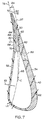
- the bowing is formed by a rotation 84 of the trailing edge block 50 as can be seen in FIG. 7 by a rotated portion 86 of the mean line 65 from an un-rotated portion 87 of the airfoil along an airfoil cross-section 88 near the base 46 or tip 48 of the airfoil 12.
- the block bow 80 is preferably graduated in the chordwise direction and the block has a maximum amount 90 of rotation 84 at the trailing edge TE as measured between the rotated portion 86 of the mean line 65, through the trailing edge block 50, from the un-rotated portion 87 of the mean line 65 of the airfoil along an airfoil cross-section 88 near the base 46 or tip 48 of the airfoil 12.
- Bowing of the trailing edge block 50 outwardly in a normal direction 82 to the pressure side portion 52 of the outer wall 40 provides additional structural capability to resist bending moments due to differential pressures between the pressure and suction side portion 52 and 54 of the airfoil outer wall.
- the trailing edge is preferably bowed outwardly in a generally aftwardly chordwise direction to provide additional aerodynamic efficiency.
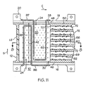
- FIGS. 8 and 11 illustrate first and second impingement cooling baffles 96 and 97 respectively within the hollow interior 22 of the airfoil 12.
- Impingement cooling holes 98 impinge cooling air 24 on inside surfaces 100 of the outer wall 40 of the airfoil 12.
- the baffles 96 and 97 schematically illustrate one possible alternative cooling air circuit to provide cooling air to pass through the film cooling holes 62 in the outer wall 40 surrounding the hollow interior 22.
Abstract

Description
- This invention relates to cooling of gas turbine engine turbine vanes and blades and, more particularly, to film cooling of airfoil trailing edges of ceramic vanes and blades.
- A gas turbine engine includes a compressor that compresses air which is channeled to a combustor wherein it is mixed with fuel and ignited for generating combustion gases. The combustion gases flow downstream through one or more stages of turbines which extract energy therefrom for powering the compressor and producing additional output power for driving a fan for powering an aircraft in flight for example. A turbine stage includes a row of turbine rotor blades secured to the outer perimeter of a rotor disk, with a stationary turbine nozzle having a plurality of stator vanes disposed upstream therefrom. The combustion gases flow between the stator vanes and between the turbine blades for extracting energy to rotate the rotor disk.
- The blades and vanes often include airfoils with hollow interiors extending between leading and trailing edges of the airfoil. Cooling air is flowed into the hollow interior for internal cooling of the airfoil and flowed out through film cooling holes for external cooling of the airfoil. The temperatures within gas turbines may exceed 2500 degrees Fahrenheit, and cooling of turbine vane and blade airfoils is very important in terms of vane and blade longevity. Without cooling, turbine vane and blade airfoils would rapidly deteriorate. Improved cooling for turbine airfoils is very desirable and much effort has been devoted by those skilled in the blade cooling arts to devise improved cooling designs in order to enhance cooling. The turbine vanes and blades are typically cooled with a portion of compressor air bled from the compressor for this purpose. Diverting any portion of the compressor air necessarily decreases the overall efficiency of the engine. Accordingly, it is desired to cool the vanes and blades with as little compressor bleed air as possible.
- Different cooling passage configurations may be used within the hollow interior of the airfoil. Straight pass through of cooling air or impingement cooling air using impingement baffles are two types of cooling configurations used within the hollow interior to cool the airfoil. Film cooling air is discharged from the hollow interior through various film cooling holes disposed around the leading edge and mid-chord areas of the outer surface of the airfoil.
- Since the overall efficiency of the gas turbine engine is directly related to the temperature of the combustion gases, engine efficiency is limited by the ability to operate the turbine nozzle at high temperature. Conventional turbine vane and blade materials are superalloys, such as single crystal nickel based materials, which have allowed engines to be operated at relatively high thermal efficiency. Further advances in engine efficiency by increasing combustion gas temperature has led to development of a class of high temperature ceramic materials one particular useful class of which is referred to as ceramic matrix composite (CMC) which have substantially higher temperature capabilities than conventional superalloys. CMC materials also maintain strength at relatively higher temperatures than that of conventional superalloys.
- However, ceramic materials are relatively brittle when compared to conventional superalloys with a corresponding loss of toughness inherent therein. These materials also have substantially different coefficients of thermal expansion, or different thermal conductivities, compared to conventional superalloys. Advanced military engines are being designed to operate under conditions that require the trailing edge to operate with greater pressure loading, about twice that of modern commercial engines. High internal pressures required to cool turbine airfoils cause ballooning stresses at the trailing edge and high pressure loading across the turbine vane causes spanwise and chordwise bending loads for which a nearly solid trailing edge provides adequate structural strength. A problem is having enough structural integrity at the trailing edge while still being able to deliver cooling flow out the trailing edge as well as bleed flow to maintain film cooling. Low strain to failure ratio materials that are brittle such as ceramics offer very good thermal characteristics. SiC-SiC, a ceramic matrix composite (CMC) material, is being considered for use for turbine vanes because of its high temperature capability. The SiC-SiC CMC is a ceramic and has a very low failure strain level and consequently, a relatively low design stress when compared to typical Ni based super alloys.
- An improved turbine airfoil and nozzle vane configuration is required that provides sufficient strength and cooling characteristics to meet the stress and temperature requirements in a high temperature and pressure environment and use ceramic materials that are characterized by a low thermal gradient capability.
- According to a first aspect of the invention, there is provided a gas turbine engine hollow turbine airfoil comprising: an outer wall surrounding a hollow interior; the outer wall extending radially outwardly in a spanwise direction from an airfoil base to an airfoil tip and having chordwise spaced apart leading and trailing edges, and widthwise spaced apart pressure and suction side portions extending chordwise between the leading edge and a trailing edge block, the trailing edge block terminating at the trailing edge; a plurality of trailing edge cooling air ducts extending chordwise through the trailing edge block aftwardly from the hollow interior; and a plurality of trailing edge film cooling holes extending from the ducts through the trailing edge block.
- The airfoil may be made from a low strain to failure ratio material.
- The airfoil may be made from a ceramic matrix composite material.
- The ceramic matrix composite material may have a SiC matrix and SiC fiber.
- The airfoil may be made from a monolithic ceramic material.
- The airfoil may be made from a low thermal gradient capability material.
- The trailing edge cooling air ducts may converge aftwardly from the hollow interior.
- The trailing edge cooling air ducts may extend aftwardly from the hollow interior completely through the trailing edge block.
- The trailing edge cooling air ducts may terminate within the trailing edge block forward of the trailing edge.
- The airfoil may further comprise throttling holes extending from the trailing edge cooling air ducts aftwardly completely through the trailing edge block.
- The trailing edge cooling air ducts may have substantially constant spanwise heights and cross-sectional widths perpendicular to a span of the airfoil that converge in an aftwardly chordwise direction from the hollow interior.
- The trailing edge cooling air ducts may extend aftwardly from the hollow interior completely through the trailing edge block.
- The trailing edge cooling air ducts may terminate within the trailing edge block forward of the trailing edge.
- The airfoil may further comprise throttling holes extending from the trailing edge cooling air ducts aftwardly and completely through the trailing edge block.
- The cooling air ducts may be centered near a neutral axis of chordwise and spanwise bending of the trailing edge block.
- The airfoil may further comprise a block bow of the trailing edge block wherein the trailing edge block is bowed outwardly in a normal direction to the pressure side portion of the outer wall.
- The block bow may have a maximum amount of rotation at the trailing edge.
- The trailing edge may be bowed outwardly in a generally aftwardly chordwise direction.
- The block bow may have a maximum point of rotation from the chord at the trailing edge.
- According to a second aspect of the invention, there is provided a gas turbine engine vane comprising: a hollow airfoil having an outer wall surrounding a hollow interior and disposed between radially inner and outer segmented platforms; the outer wall extending radially outwardly from an airfoil base to an airfoil tip and having chordwise spaced apart leading and trailing edges, and widthwise spaced apart pressure and suction side portions extending chordwise between the leading edge and a trailing edge block, the trailing edge block terminating at the trailing edge; a plurality of trailing edge cooling air ducts extending chordwise through the trailing edge block aftwardly from the hollow interior; and a plurality of trailing edge film cooling holes extending from the ducts through the trailing edge block.
- The vane may be made from a ceramic matrix composite material.
- The ceramic matrix composite material may have a SiC matrix.
- The trailing edge cooling air ducts may converge aftwardly from the hollow interior.
- The trailing edge cooling air ducts may extend aftwardly from the hollow interior completely through the trailing edge block.
- The trailing edge cooling air ducts may terminate within the trailing edge block forward of the trailing edge.
- The vane as may further comprise throttling holes extending from the trailing edge cooling air ducts aftwardly completely through the trailing edge block.
- The trailing edge cooling air ducts may have substantially constant spanwise heights and converging cross-sectional widths perpendicular to a span of the airfoil that converge in an aftwardly chordwise direction from the hollow interior.
- The trailing edge cooling air ducts may extend aftwardly from the hollow interior completely through the trailing edge block.
- The trailing edge cooling air ducts may terminate within the trailing edge block forward of the trailing edge.
- The vane may further comprise throttling holes extending from the trailing edge cooling air ducts aftwardly and completely through the trailing edge block.
- The cooling air ducts may be centered near a neutral axis of chordwise and spanwise bending of the trailing edge block.
- The vane may further comprise a block bow of the trailing edge block wherein the trailing edge block is bowed outwardly in a normal direction to the pressure side portion of the outer wall.
- The block bow may be graduated in the chordwise direction.
- The block bow may have a maximum amount of rotation along the trailing edge.
- The trailing edge may be bowed outwardly in a generally aftwardly chordwise direction.
- The block bow may have a maximum amount of rotation at the trailing edge.
- The vane may be made from a monolithic ceramic material.
- The airfoil vane may be made from a low thermal gradient capability material.
- Thus, a gas turbine engine hollow turbine airfoil suitable for use in a turbine vane includes an outer wall surrounding a hollow interior. The airfoil has pressure and suction sides extending aftwardly in a chordwise direction from a leading edge to a trailing edge. The outer wall extends radially outwardly in a spanwise direction from an airfoil base to an airfoil tip and widthwise spaced apart pressure and suction side portions extending chordwise between the leading edge and a trailing edge block. The trailing edge block extends aftwardly from the hollow interior and terminates at the trailing edge, a plurality of trailing edge cooling air ducts extend chordwise through the trailing edge block aftwardly from the hollow interior, and a plurality of trailing edge film cooling holes extend from the ducts through the trailing edge block. The cooling air ducts are preferably centered along or near a neutral axis of chordwise and spanwise bending of the trailing edge block. The invention is particularly suitable for turbine airfoils and vanes made with a ceramic matrix composite material such as one having a SiC matrix and, more particularly, with an SiC-SiC ceramic matrix composite. The trailing edge cooling air ducts converge aftwardly from the hollow interior. In a more particular embodiment, the trailing edge cooling air ducts converge in width and have a substantially constant spanwise height.
- The invention includes, but is not limited to, three embodiments with means for terminating the trailing edge cooling air ducts. In the first embodiment, the trailing edge cooling air ducts extend aftwardly from the hollow interior completely through the trailing edge block. In the second embodiment, the trailing edge cooling air ducts terminate within the trailing edge block forward of the trailing edge. In the third embodiment, throttling holes extend from the trailing edge cooling air ducts, which terminate within the block, aftwardly completely through the trailing edge block. The trailing edge cooling air ducts have substantially constant spanwise heights and converging cross-sectional widths perpendicular to a span of the airfoil that converge in an aftwardly chordwise direction from the hollow interior.
- In one more particular embodiment, the trailing edge block has a block spanwise bow wherein the trailing edge block is bowed outwardly in a normal direction to the pressure side of the airfoil. The block spanwise bow is preferably graduated in the chordwise direction to minimize bending of the airfoil trailing edge block near the trailing edge. The trailing edge is preferably bowed outwardly in a generally aftwardly chordwise direction.
- The airfoil of the present invention is particularly suitable in a vane for a gas turbine engine such as the first stage of a high pressure turbine. The vane includes the hollow airfoil disposed between radially inner and outer segmented platforms that are integrally formed of a ceramic matrix composite (CMC) preferably a SiC-SiC CMC.
- The invention will now be described in greater detail, by way of example, with reference to the drawings, in which:-
- FIG. 1 is a perspective view illustration of a gas turbine engine turbine vane illustrating a first exemplary embodiment of the invention.
- FIG. 2 is a sectional schematic illustration of an airfoil cross-section through line 2-2 of an airfoil of the vane in FIG. 3.
- FIG. 3 is a sectional schematic illustration through the vane in FIG. 1 which is laid out flat along a mean line through the vane illustrating cooling air ducts in the trailing block terminating at the trailing edge of the airfoil.
- FIG. 4 is a sectional schematic illustration of a second embodiment of the vane in FIG. 1 which is laid out flat along a mean line through the vane illustrating cooling air ducts in the trailing block terminating within the block forward of the trailing edge of the airfoil.
- FIG. 5 is a sectional schematic illustration of a third embodiment of the vane in FIG. 1 which is laid out flat along a mean line through the vane illustrating cooling air ducts in the trailing block terminating within the block forward of the trailing edge of the airfoil and having throttling holes to purge cooling air from the ducts out the trailing edge.
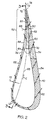
- FIG. 6 is an aft looking forward perspective view illustration of the gas turbine engine turbine vane in FIG. 1 illustrating a bowed block bowed outward in a direction faced by a pressure side of the airfoil.
- FIG. 7 is a sectional schematic illustration of a mid-span airfoil cross-section through line 7-7 of the airfoil of the vane in FIG. 3 and illustrates bowing of a trailing edge block of the airfoil.
- FIG. 8 is a sectional schematic illustration of an airfoil cross-section through line 2-2 of an airfoil of the vane in FIG. 3 with impingement cooling baffles inside a hollow interior of the airfoil.
- FIG. 9 is a sectional schematic illustration of an airfoil cross-section through line 9-9 of an airfoil of the vane in FIG. 4.
- FIG. 10 is a sectional schematic illustration of an airfoil cross-section through line 10-10 of an airfoil of the vane in FIG. 5.
- FIG. 11 is a sectional schematic illustration through the vane in FIG. 1 which is laid out flat along a mean line through the vane illustrating an alternative embodiment of the invention with impingement baffles used for supplying cooling air to the hollow interior of the airfoil.
- FIG. 12 is an aft looking forward perspective view illustration of the gas turbine engine turbine vane in FIG. 3 illustrating ovalized cooling air duct outlets at the trailing edge of the airfoil.
-
- Illustrated in FIGS. 1 and 2 is a
turbine vane 10 that has particular use in a first stage high pressure turbine section in a gas turbine engine and includes at least onehollow airfoil 12 extending radially between arcuate radially inner and outersegmented platforms flanges 20 which support thevane 10 from fixed structure of the engine. Thehollow airfoil 12 has ahollow interior 22 for receiving coolingair 24. Thehollow interior 22 is schematically illustrated as a single pass cooling air circuit in the exemplary embodiment illustrated herein with the coolingair 24 flowing from a radiallyouter opening 28 to a radiallyinner opening 30 of theairfoil 12. - The
vanes 10 including thehollow airfoil 12, inner and outersegmented platforms flanges 20 are integrally formed of a low strain to failure ratio material, such as a ceramic or ceramic matrix composite (CMC) such as a SiC-SiC CMC, a silicon infiltrated silicon carbide composite reinforced with coated silicon carbide fibers. The ceramic material may be a monolithic ceramic material such as SiC. These ceramic materials are characterized by a low thermal gradient capability. - The
airfoil 12 has anouter wall 40 with aspan 42 extending radially outwardly in a spanwise direction S from anairfoil base 46 at theinner segment platform 16 to anairfoil tip 48 at the outersegmented platform 18. Theairfoil 12 includes pressure andsuction sides outer wall 40 has widthwise (widthwise direction denoted as W perpendicular to the chord C) spaced apart pressure andsuction side portions edge block 50. The trailingedge block 50 extends from thehollow interior 22 to the trailing edge TE where it terminates. The trailingedge block 50 is nearly solid because high internal pressures of the coolingair 24 inside thehollow interior 22 causes ballooning stresses at the trailing edge portion represented by the block. This high pressure loading across the airfoil causes spanwise and chordwise bending loads that necessitate a nearly solid trailing edge portion of the airfoil. Thesuction side portion 54 has a first thickness T1 substantially greater than a pressure wall second thickness T2 of thepressure side portion 52 because at operating conditions a first pressure drop across thesuction side portion 54 is substantially greater than a second pressure drop across thepressure side portion 52. - A plurality of trailing edge cooling
air ducts 60 extend chordwise through the trailingedge block 50 aftwardly from thehollow interior 22 and a plurality of trailing edge film cooling holes 62 extend from the ducts through the trailing edge block. Film cooling holes 62 are also disposed through the pressure andsuction side portions air ducts 60 are preferably centered along or near aneutral axis 64 of chordwise and spanwise bending of the trailingedge block 50. As used herein, the neutral bending axis is defined as the locus of points defining a plane of the trailingedge block 50 which will experience zero stress under chordwise and/or spanwise bending. Typically, theneutral axis 64 will approximate an airfoilmean line 65 and is determinable by known methods. The exemplary embodiment illustrated herein shows theneutral axis 64 near themean line 65. - The trailing edge cooling
air ducts 60 converge in an aftwardly chordwise direction from thehollow interior 22. Preferably, the trailing edge coolingair ducts 60 converge in width only such that they have substantially constantspanwise heights 66, as illustrated in FIGS. 3, 4, and 5, and convergingcross-sectional widths 68 that are perpendicular to thespan 42 of theairfoil 12 as illustrated in FIG. 2. The substantially constantspanwise heights 66 of theair ducts 60 provide a maximum amount ofinter-duct material 69 between the air ducts in the trailingedge block 50 which helps to resist the high pressure loading across the airfoil and the resulting large spanwise and chordwise bending loads. The coolingair ducts 60 have filletedround inlets 70 and because they converge in width only they have oval or race track shapedoutlets 72 as illustrated in FIG. 12. The coolingair ducts 60 gradually transition in shape between theinlets 70 and theoutlets 72. The convergingcooling air ducts 60 are designed to provide sufficient pressure of the coolingair 24 inside the ducts to provide film cooling through the trailing edge film cooling holes 62 through the trailingedge block 50. They are also designed to provide flow rates of the coolingair 24 that result in substantially constant heat transfer cooling surface area and lower cooling heat flux levels, which benefits the CMC material which has generally lower stress capabilities for through wall temperature gradients. This provides good heat transfer loading for the trailingedge block 50 with both effective internal convection through the film cooling holes 62 and good external film cooling to maintain the temperature limits of the CMC material in the block. - The invention, thus, provides sufficient and substantial structural integrity at the trailing
edge block 50 while still being able to deliver coolingair 24 out the film cooling holes 62 in the trailing edge block as well as bleed flow 78 to maintain film cooling. Structurally, the coolingair ducts 60 are near theneutral axis 64 of chordwise and spanwise bending of the trailingedge block 50. From a structural standpoint, the coolingair ducts 60 should be as close as possible to theneutral axis 64. The amount ofinter-duct material 69 between the air ducts in the trailingedge block 50 allows the transverse shear stresses from bending to be transferred from the thinnerpressure side portion 52 to the thickersuction side portion 54, which because of its greater thickness, has greater load bearing capability than the pressure side portion. This greatly enhances the structural integrity of and cooling air delivery to the trailingedge block 50 which is made of low strength and low ductility materials such as SiC-SiC CMCs. - The invention includes, but is not limited to, three embodiments of designs for terminating the trailing edge cooling
air ducts 60. Illustrated in FIGS. 2 and 3 is the first embodiment in which the trailing edge coolingair ducts 60 extend aftwardly from thehollow interior 22 completely through the trailingedge block 50 ending atoutlets 72 as described above. In the second embodiment illustrated in FIG. 4, the trailing edge coolingair ducts 60 terminate within the trailing edge block forward of the trailing edge TE. All of the coolingair 24 inside theducts 60 is used to provide film cooling through the trailing edge film cooling holes 62 through the trailingedge block 50. In the third embodiment illustrated in FIG. 5, throttlingholes 76 extend from the trailing edge coolingair ducts 60, which terminate within the block, aftwardly completely through the trailingedge block 50. - Illustrated in FIGS. 6 and 7 is the trailing
edge block 50 having ablock bow 80 wherein the trailing edge block is bowed outwardly in anormal direction 82 to thepressure side portion 52 of theouter wall 40. The bowing is formed by arotation 84 of the trailingedge block 50 as can be seen in FIG. 7 by a rotatedportion 86 of themean line 65 from anun-rotated portion 87 of the airfoil along anairfoil cross-section 88 near the base 46 ortip 48 of theairfoil 12. Theblock bow 80 is preferably graduated in the chordwise direction and the block has amaximum amount 90 ofrotation 84 at the trailing edge TE as measured between the rotatedportion 86 of themean line 65, through the trailingedge block 50, from theun-rotated portion 87 of themean line 65 of the airfoil along anairfoil cross-section 88 near the base 46 ortip 48 of theairfoil 12. Bowing of the trailingedge block 50 outwardly in anormal direction 82 to thepressure side portion 52 of theouter wall 40 provides additional structural capability to resist bending moments due to differential pressures between the pressure andsuction side portion - FIGS. 8 and 11 illustrate first and second impingement cooling baffles 96 and 97 respectively within the
hollow interior 22 of theairfoil 12. Impingement cooling holes 98 impinge coolingair 24 oninside surfaces 100 of theouter wall 40 of theairfoil 12. Thebaffles outer wall 40 surrounding thehollow interior 22.
Claims (10)
- A gas turbine engine hollow turbine airfoil (12) comprising:an outer wall (40) surrounding a hollow interior (22);said outer wall (40) extending radially outwardly in a spanwise direction (S) from an airfoil base (46) to an airfoil tip (48) and having chordwise spaced apart leading and trailing edges (LE, TE), and widthwise spaced apart pressure and suction side portions (52, 54) extending chordwise between said leading edge (LE) and a trailing edge block (50), said trailing edge block (50) terminating at said trailing edge;a plurality of trailing edge cooling air ducts (60) extending chordwise through said trailing edge block (50) aftwardly from said hollow interior (22); anda plurality of trailing edge film cooling holes (62) extending from said ducts through said trailing edge block (50).
- An airfoil (12) as claimed in claim 1 wherein said airfoil (12) is made from a low strain to failure ratio material.
- An airfoil (12) as claimed in claim 1 wherein said airfoil (12) is made from a ceramic matrix composite material.
- An airfoil (12) as claimed in claim 3 wherein said ceramic matrix composite material has a SiC matrix and SiC fiber.
- An airfoil (12) as claimed in claim 1 wherein said airfoil (12) is made from a monolithic ceramic material.
- A gas turbine engine vane (10) comprising:a hollow airfoil (12) having an outer wall (40) surrounding a hollow interior (22) and disposed between radially inner and outer segmented platforms (16, 18);said outer wall (40) extending radially outwardly from an airfoil base (46) to an airfoil tip (48) and having chordwise spaced apart leading and trailing edges (LE, TE), and widthwise spaced apart pressure and suction side portions (52, 54) extending chordwise between said leading edge (LE) and a trailing edge block (50), said trailing edge block (50) terminating at said trailing edge;a plurality of trailing edge cooling air ducts (60) extending chordwise through said trailing edge block (50) aftwardly from said hollow interior (22); anda plurality of trailing edge film cooling holes (62) extending from said ducts through said trailing edge block (50).
- A vane (10) as claimed in claim 6 wherein said vane (10) is made from a ceramic matrix composite material.
- A vane (10) as claimed in claim 7 wherein said ceramic matrix composite material has a SiC matrix.
- A vane (10) as claimed in claim 6, 7 or 8 wherein said trailing edge cooling air ducts (60) converge aftwardly from said hollow interior (22).
- A vane (10) as claimed in claim 9 wherein said trailing edge cooling air ducts (60) extend aftwardly from said hollow interior (22) completely through said trailing edge block (50).
Applications Claiming Priority (2)
| Application Number | Priority Date | Filing Date | Title |
|---|---|---|---|
| US507407 | 2000-02-18 | ||
| US09/507,407 US6325593B1 (en) | 2000-02-18 | 2000-02-18 | Ceramic turbine airfoils with cooled trailing edge blocks |
Publications (3)
| Publication Number | Publication Date |
|---|---|
| EP1126135A2 true EP1126135A2 (en) | 2001-08-22 |
| EP1126135A3 EP1126135A3 (en) | 2003-01-08 |
| EP1126135B1 EP1126135B1 (en) | 2006-06-07 |
Family
ID=24018525
Family Applications (1)
| Application Number | Title | Priority Date | Filing Date |
|---|---|---|---|
| EP00311265A Expired - Lifetime EP1126135B1 (en) | 2000-02-18 | 2000-12-15 | Ceramic turbine airfoils with cooled trailing edge blocks |
Country Status (4)
| Country | Link |
|---|---|
| US (1) | US6325593B1 (en) |
| EP (1) | EP1126135B1 (en) |
| JP (1) | JP4883834B2 (en) |
| DE (1) | DE60028529T2 (en) |
Cited By (23)
| Publication number | Priority date | Publication date | Assignee | Title |
|---|---|---|---|---|
| EP1231358A2 (en) * | 2001-02-08 | 2002-08-14 | General Electric Company | Airfoil shape for a turbine nozzle |
| US6837683B2 (en) | 2001-11-21 | 2005-01-04 | Rolls-Royce Plc | Gas turbine engine aerofoil |
| EP1367037A3 (en) * | 2002-05-31 | 2005-11-09 | Siemens Westinghouse Power Corporation | Ceramic matrix composite turbine vane |
| EP1669544A1 (en) * | 2004-12-13 | 2006-06-14 | The General Electric Company | Turbine stage with film cooled fillet |
| WO2007029072A2 (en) * | 2005-09-06 | 2007-03-15 | L'air Liquide, Societe Anonyme Pour L'etude Et L'exploitation Des Procedes Georges Claude | Flexible flow control device for cogeneration ducting applications |
| EP1795707A2 (en) * | 2005-12-08 | 2007-06-13 | The General Electric Company | Leading edge fillet for gas turbine engine nozzle . |
| WO2007081347A2 (en) | 2005-01-18 | 2007-07-19 | Siemens Power Generation, Inc. | Ceramic matrix composite vane with chordwise stiffener |
| EP1788193A3 (en) * | 2005-11-17 | 2009-10-28 | Kawasaki Jukogyo Kabushiki Kaisha | Double jet film cooling arrangement |
| WO2010142747A1 (en) * | 2009-06-10 | 2010-12-16 | Snecma | Method for machining cmc turbine blades using a pcd tool |
| WO2011005337A1 (en) * | 2009-07-08 | 2011-01-13 | General Electric Company | Composite turbine nozzle segment |
| US7934906B2 (en) | 2007-11-14 | 2011-05-03 | Siemens Energy, Inc. | Turbine blade tip cooling system |
| EP2612994A1 (en) * | 2012-01-05 | 2013-07-10 | General Electric Company | System and method for cooling turbine blades |
| JP2014111901A (en) * | 2012-12-05 | 2014-06-19 | Hitachi Ltd | Gas turbine cooling blade and method for repairing gas turbine cooling blade |
| WO2015012918A2 (en) | 2013-06-04 | 2015-01-29 | United Technologies Corporation | Gas turbine engine airfoil trailing edge suction side cooling |
| WO2015021086A1 (en) * | 2013-08-06 | 2015-02-12 | General Electric Company | Mounting apparatus for low-ductility turbine nozzle |
| EP2867475A4 (en) * | 2012-07-02 | 2015-09-02 | United Technologies Corp | Airfoil cooling arrangement |
| WO2018009261A3 (en) * | 2016-05-11 | 2018-02-15 | General Electric Company | Ceramic matrix composite airfoil cooling |
| EP3290638A1 (en) * | 2016-09-02 | 2018-03-07 | United Technologies Corporation | Cooled turbine vane with alternately orientated film cooling hole rows |
| EP3460191A1 (en) * | 2017-09-21 | 2019-03-27 | United Technologies Corporation | Gas turbine engine component with cooling holes having variable roughness |
| EP3808940A1 (en) * | 2019-10-15 | 2021-04-21 | Raytheon Technologies Corporation | Cmc airfoil with cooling holes |
| US11242760B2 (en) * | 2020-01-22 | 2022-02-08 | General Electric Company | Turbine rotor blade with integral impingement sleeve by additive manufacture |
| CN114439554A (en) * | 2020-10-30 | 2022-05-06 | 通用电气公司 | CMC nozzle assembly for gas turbine engine fabrication |
| EP4119772A1 (en) * | 2021-07-16 | 2023-01-18 | Raytheon Technologies Corporation | Airfoil assembly with fiber-reinforced composite rings and toothed exit slot |
Families Citing this family (99)
| Publication number | Priority date | Publication date | Assignee | Title |
|---|---|---|---|---|
| US6543993B2 (en) * | 2000-12-28 | 2003-04-08 | General Electric Company | Apparatus and methods for localized cooling of gas turbine nozzle walls |
| US6709230B2 (en) | 2002-05-31 | 2004-03-23 | Siemens Westinghouse Power Corporation | Ceramic matrix composite gas turbine vane |
| US7093359B2 (en) | 2002-09-17 | 2006-08-22 | Siemens Westinghouse Power Corporation | Composite structure formed by CMC-on-insulation process |
| US9068464B2 (en) * | 2002-09-17 | 2015-06-30 | Siemens Energy, Inc. | Method of joining ceramic parts and articles so formed |
| US6808363B2 (en) * | 2002-12-20 | 2004-10-26 | General Electric Company | Shroud segment and assembly with circumferential seal at a planar segment surface |
| US6884030B2 (en) | 2002-12-20 | 2005-04-26 | General Electric Company | Methods and apparatus for securing multi-piece nozzle assemblies |
| US6893214B2 (en) * | 2002-12-20 | 2005-05-17 | General Electric Company | Shroud segment and assembly with surface recessed seal bridging adjacent members |
| US7311790B2 (en) * | 2003-04-25 | 2007-12-25 | Siemens Power Generation, Inc. | Hybrid structure using ceramic tiles and method of manufacture |
| US20050158171A1 (en) * | 2004-01-15 | 2005-07-21 | General Electric Company | Hybrid ceramic matrix composite turbine blades for improved processibility and performance |
| US7351364B2 (en) * | 2004-01-29 | 2008-04-01 | Siemens Power Generation, Inc. | Method of manufacturing a hybrid structure |
| US7086829B2 (en) * | 2004-02-03 | 2006-08-08 | General Electric Company | Film cooling for the trailing edge of a steam cooled nozzle |
| US7066717B2 (en) * | 2004-04-22 | 2006-06-27 | Siemens Power Generation, Inc. | Ceramic matrix composite airfoil trailing edge arrangement |
| GB2417295B (en) * | 2004-08-21 | 2006-10-25 | Rolls Royce Plc | A component having a cooling arrangement |
| US8137611B2 (en) * | 2005-03-17 | 2012-03-20 | Siemens Energy, Inc. | Processing method for solid core ceramic matrix composite airfoil |
| US7316539B2 (en) * | 2005-04-07 | 2008-01-08 | Siemens Power Generation, Inc. | Vane assembly with metal trailing edge segment |
| US7452182B2 (en) * | 2005-04-07 | 2008-11-18 | Siemens Energy, Inc. | Multi-piece turbine vane assembly |
| US7393183B2 (en) * | 2005-06-17 | 2008-07-01 | Siemens Power Generation, Inc. | Trailing edge attachment for composite airfoil |
| US7563071B2 (en) * | 2005-08-04 | 2009-07-21 | Siemens Energy, Inc. | Pin-loaded mounting apparatus for a refractory component in a combustion turbine engine |
| US7371043B2 (en) * | 2006-01-12 | 2008-05-13 | Siemens Power Generation, Inc. | CMC turbine shroud ring segment and fabrication method |
| US7600978B2 (en) * | 2006-07-27 | 2009-10-13 | Siemens Energy, Inc. | Hollow CMC airfoil with internal stitch |
| US20100034662A1 (en) * | 2006-12-26 | 2010-02-11 | General Electric Company | Cooled airfoil and method for making an airfoil having reduced trail edge slot flow |
| US7722317B2 (en) * | 2007-01-25 | 2010-05-25 | Siemens Energy, Inc. | CMC to metal attachment mechanism |
| JP5474279B2 (en) * | 2007-03-06 | 2014-04-16 | 株式会社Ihi | Cooling turbine blade |
| US20090014926A1 (en) * | 2007-07-09 | 2009-01-15 | Siemens Power Generation, Inc. | Method of constructing a hollow fiber reinforced structure |
| US7967570B2 (en) * | 2007-07-27 | 2011-06-28 | United Technologies Corporation | Low transient thermal stress turbine engine components |
| JP4577662B2 (en) * | 2007-10-11 | 2010-11-10 | 株式会社Ihi | Turbine blade |
| WO2009048357A1 (en) * | 2007-10-11 | 2009-04-16 | Volvo Aero Corporation | A method for producing a vane, such a vane and a stator component comprising the vane |
| US8096770B2 (en) * | 2008-09-25 | 2012-01-17 | Siemens Energy, Inc. | Trailing edge cooling for turbine blade airfoil |
| US8382436B2 (en) | 2009-01-06 | 2013-02-26 | General Electric Company | Non-integral turbine blade platforms and systems |
| US8262345B2 (en) * | 2009-02-06 | 2012-09-11 | General Electric Company | Ceramic matrix composite turbine engine |
| US9422816B2 (en) * | 2009-06-26 | 2016-08-23 | United Technologies Corporation | Airfoil with hybrid drilled and cutback trailing edge |
| US8256088B2 (en) * | 2009-08-24 | 2012-09-04 | Siemens Energy, Inc. | Joining mechanism with stem tension and interlocked compression ring |
| JP5709879B2 (en) * | 2009-10-20 | 2015-04-30 | シーメンス エナジー インコーポレイテッド | Gas turbine engine |
| US8894363B2 (en) | 2011-02-09 | 2014-11-25 | Siemens Energy, Inc. | Cooling module design and method for cooling components of a gas turbine system |
| US8632297B2 (en) | 2010-09-29 | 2014-01-21 | General Electric Company | Turbine airfoil and method for cooling a turbine airfoil |
| US8790067B2 (en) | 2011-04-27 | 2014-07-29 | United Technologies Corporation | Blade clearance control using high-CTE and low-CTE ring members |
| US9011085B2 (en) * | 2011-05-26 | 2015-04-21 | United Technologies Corporation | Ceramic matrix composite continuous “I”-shaped fiber geometry airfoil for a gas turbine engine |
| US8739547B2 (en) | 2011-06-23 | 2014-06-03 | United Technologies Corporation | Gas turbine engine joint having a metallic member, a CMC member, and a ceramic key |
| US8864492B2 (en) | 2011-06-23 | 2014-10-21 | United Technologies Corporation | Reverse flow combustor duct attachment |
| US9335051B2 (en) | 2011-07-13 | 2016-05-10 | United Technologies Corporation | Ceramic matrix composite combustor vane ring assembly |
| US8920127B2 (en) | 2011-07-18 | 2014-12-30 | United Technologies Corporation | Turbine rotor non-metallic blade attachment |
| US8834109B2 (en) * | 2011-08-03 | 2014-09-16 | United Technologies Corporation | Vane assembly for a gas turbine engine |
| US8882448B2 (en) | 2011-09-09 | 2014-11-11 | Siemens Aktiengesellshaft | Cooling system in a turbine airfoil assembly including zigzag cooling passages interconnected with radial passageways |
| US8840363B2 (en) | 2011-09-09 | 2014-09-23 | Siemens Energy, Inc. | Trailing edge cooling system in a turbine airfoil assembly |
| JP5536001B2 (en) * | 2011-09-20 | 2014-07-02 | 株式会社日立製作所 | Gas turbine blade film cooling hole setting method and gas turbine blade |
| US9127560B2 (en) | 2011-12-01 | 2015-09-08 | General Electric Company | Cooled turbine blade and method for cooling a turbine blade |
| US8967974B2 (en) | 2012-01-03 | 2015-03-03 | General Electric Company | Composite airfoil assembly |
| US9587492B2 (en) | 2012-05-04 | 2017-03-07 | General Electric Company | Turbomachine component having an internal cavity reactivity neutralizer and method of forming the same |
| US9670790B2 (en) | 2012-09-28 | 2017-06-06 | United Technologies Corporation | Turbine vane with mistake reduction feature |
| US9790801B2 (en) * | 2012-12-27 | 2017-10-17 | United Technologies Corporation | Gas turbine engine component having suction side cutback opening |
| US20140208771A1 (en) * | 2012-12-28 | 2014-07-31 | United Technologies Corporation | Gas turbine engine component cooling arrangement |
| US8985949B2 (en) | 2013-04-29 | 2015-03-24 | Siemens Aktiengesellschaft | Cooling system including wavy cooling chamber in a trailing edge portion of an airfoil assembly |
| US20150184518A1 (en) * | 2013-12-26 | 2015-07-02 | Ching-Pang Lee | Turbine airfoil cooling system with nonlinear trailing edge exit slots |
| EP2921649B1 (en) * | 2014-03-19 | 2021-04-28 | Ansaldo Energia IP UK Limited | Airfoil portion of a rotor blade or guide vane of a turbo-machine |
| EP3023696B1 (en) * | 2014-11-20 | 2019-08-28 | Ansaldo Energia Switzerland AG | Lobe lance for a gas turbine combustor |
| US9810084B1 (en) * | 2015-02-06 | 2017-11-07 | United Technologies Corporation | Gas turbine engine turbine vane baffle and serpentine cooling passage |
| CN104895618B (en) * | 2015-04-10 | 2017-02-01 | 中国科学院工程热物理研究所 | Super-high load low pressure turbine blade, high load low pressure turbine and aviation gas turbine engine |
| US10024175B2 (en) | 2015-05-26 | 2018-07-17 | Rolls-Royce Corporation | Cooling holes manufactured with EBC in place |
| US9797263B2 (en) | 2015-05-26 | 2017-10-24 | Rolls-Royce Corporation | Monolithic ceramic rods to enable cooling holes in CMC |
| US9702551B2 (en) * | 2015-06-11 | 2017-07-11 | Haier Us Appliance Solutions, Inc. | Gas burner |
| DE102015213090A1 (en) * | 2015-07-13 | 2017-01-19 | Siemens Aktiengesellschaft | Blade for a turbomachine and method for its production |
| US11230935B2 (en) | 2015-09-18 | 2022-01-25 | General Electric Company | Stator component cooling |
| US20170089579A1 (en) * | 2015-09-30 | 2017-03-30 | General Electric Company | Cmc articles having small complex features for advanced film cooling |
| US10563867B2 (en) * | 2015-09-30 | 2020-02-18 | General Electric Company | CMC articles having small complex features for advanced film cooling |
| US10344598B2 (en) | 2015-12-03 | 2019-07-09 | General Electric Company | Trailing edge cooling for a turbine blade |
| US20170176012A1 (en) * | 2015-12-22 | 2017-06-22 | General Electric Company | Fuel injectors and staged fuel injection systems in gas turbines |
| US10408073B2 (en) | 2016-01-20 | 2019-09-10 | General Electric Company | Cooled CMC wall contouring |
| US10309254B2 (en) * | 2016-02-26 | 2019-06-04 | General Electric Company | Nozzle segment for a gas turbine engine with ribs defining radially spaced internal cooling channels |
| JP6681749B2 (en) * | 2016-03-03 | 2020-04-15 | 三菱航空機株式会社 | High-temperature airframe structure and aircraft |
| US10519779B2 (en) * | 2016-03-16 | 2019-12-31 | General Electric Company | Radial CMC wall thickness variation for stress response |
| US10494930B2 (en) | 2016-06-16 | 2019-12-03 | General Electric Company | Ceramic matrix composite component cooling |
| US10570751B2 (en) | 2017-11-22 | 2020-02-25 | General Electric Company | Turbine engine airfoil assembly |
| US11008888B2 (en) | 2018-07-17 | 2021-05-18 | Rolls-Royce Corporation | Turbine vane assembly with ceramic matrix composite components |
| US10830063B2 (en) | 2018-07-20 | 2020-11-10 | Rolls-Royce North American Technologies Inc. | Turbine vane assembly with ceramic matrix composite components |
| US10605103B2 (en) | 2018-08-24 | 2020-03-31 | Rolls-Royce Corporation | CMC airfoil assembly |
| US10927689B2 (en) * | 2018-08-31 | 2021-02-23 | Rolls-Royce Corporation | Turbine vane assembly with ceramic matrix composite components mounted to case |
| US10767497B2 (en) | 2018-09-07 | 2020-09-08 | Rolls-Royce Corporation | Turbine vane assembly with ceramic matrix composite components |
| US11149567B2 (en) | 2018-09-17 | 2021-10-19 | Rolls-Royce Corporation | Ceramic matrix composite load transfer roller joint |
| US10890077B2 (en) | 2018-09-26 | 2021-01-12 | Rolls-Royce Corporation | Anti-fret liner |
| US10859268B2 (en) | 2018-10-03 | 2020-12-08 | Rolls-Royce Plc | Ceramic matrix composite turbine vanes and vane ring assemblies |
| US11149568B2 (en) | 2018-12-20 | 2021-10-19 | Rolls-Royce Plc | Sliding ceramic matrix composite vane assembly for gas turbine engines |
| US11047247B2 (en) | 2018-12-21 | 2021-06-29 | Rolls-Royce Plc | Turbine section of a gas turbine engine with ceramic matrix composite vanes |
| US10961857B2 (en) | 2018-12-21 | 2021-03-30 | Rolls-Royce Plc | Turbine section of a gas turbine engine with ceramic matrix composite vanes |
| US10767493B2 (en) | 2019-02-01 | 2020-09-08 | Rolls-Royce Plc | Turbine vane assembly with ceramic matrix composite vanes |
| US10883376B2 (en) | 2019-02-01 | 2021-01-05 | Rolls-Royce Plc | Turbine vane assembly with ceramic matrix composite vanes |
| US10954802B2 (en) | 2019-04-23 | 2021-03-23 | Rolls-Royce Plc | Turbine section assembly with ceramic matrix composite vane |
| US10975708B2 (en) | 2019-04-23 | 2021-04-13 | Rolls-Royce Plc | Turbine section assembly with ceramic matrix composite vane |
| US11008880B2 (en) | 2019-04-23 | 2021-05-18 | Rolls-Royce Plc | Turbine section assembly with ceramic matrix composite vane |
| US11193393B2 (en) | 2019-04-23 | 2021-12-07 | Rolls-Royce Plc | Turbine section assembly with ceramic matrix composite vane |
| US11149559B2 (en) | 2019-05-13 | 2021-10-19 | Rolls-Royce Plc | Turbine section assembly with ceramic matrix composite vane |
| US11193381B2 (en) | 2019-05-17 | 2021-12-07 | Rolls-Royce Plc | Turbine vane assembly having ceramic matrix composite components with sliding support |
| US10890076B1 (en) | 2019-06-28 | 2021-01-12 | Rolls-Royce Plc | Turbine vane assembly having ceramic matrix composite components with expandable spar support |
| US11162432B2 (en) * | 2019-09-19 | 2021-11-02 | General Electric Company | Integrated nozzle and diaphragm with optimized internal vane thickness |
| JP6745012B1 (en) * | 2019-10-31 | 2020-08-26 | 三菱日立パワーシステムズ株式会社 | Turbine blade and gas turbine equipped with the same |
| US11473444B2 (en) * | 2019-11-08 | 2022-10-18 | Raytheon Technologies Corporation | Ceramic airfoil with cooling air turn |
| US11319822B2 (en) | 2020-05-06 | 2022-05-03 | Rolls-Royce North American Technologies Inc. | Hybrid vane segment with ceramic matrix composite airfoils |
| US11560799B1 (en) | 2021-10-22 | 2023-01-24 | Rolls-Royce High Temperature Composites Inc. | Ceramic matrix composite vane assembly with shaped load transfer features |
| US11732596B2 (en) | 2021-12-22 | 2023-08-22 | Rolls-Royce Plc | Ceramic matrix composite turbine vane assembly having minimalistic support spars |
| US11713679B1 (en) * | 2022-01-27 | 2023-08-01 | Raytheon Technologies Corporation | Tangentially bowed airfoil |
Citations (2)
| Publication number | Priority date | Publication date | Assignee | Title |
|---|---|---|---|---|
| US5326224A (en) * | 1991-03-01 | 1994-07-05 | General Electric Company | Cooling hole arrangements in jet engine components exposed to hot gas flow |
| EP1106782A2 (en) * | 1999-12-09 | 2001-06-13 | General Electric Company | Cooled airfoil for gas turbine engine and method of making the same |
Family Cites Families (24)
| Publication number | Priority date | Publication date | Assignee | Title |
|---|---|---|---|---|
| US3515499A (en) * | 1968-04-22 | 1970-06-02 | Aerojet General Co | Blades and blade assemblies for turbine engines,compressors and the like |
| US3819295A (en) | 1972-09-21 | 1974-06-25 | Gen Electric | Cooling slot for airfoil blade |
| GB1560683A (en) * | 1972-11-28 | 1980-02-06 | Rolls Royce | Turbine blade |
| US4006999A (en) | 1975-07-17 | 1977-02-08 | The United States Of America As Represented By The Administrator Of The National Aeronautics And Space Administration | Leading edge protection for composite blades |
| US4203706A (en) * | 1977-12-28 | 1980-05-20 | United Technologies Corporation | Radial wafer airfoil construction |
| US4324843A (en) * | 1980-02-13 | 1982-04-13 | United Technologies Corporation | Continuous length silicon carbide fiber reinforced ceramic composites |
| GB2097479B (en) | 1981-04-24 | 1984-09-05 | Rolls Royce | Cooled vane for a gas turbine engine |
| JPS60187701A (en) * | 1984-03-06 | 1985-09-25 | Toshiba Corp | Gas turbine cooling blade |
| US4705455A (en) | 1985-12-23 | 1987-11-10 | United Technologies Corporation | Convergent-divergent film coolant passage |
| GB2189553B (en) | 1986-04-25 | 1990-05-23 | Rolls Royce | Cooled vane |
| US5102299A (en) | 1986-11-10 | 1992-04-07 | The United States Of America As Represented By The Secretary Of The Air Force | Airfoil trailing edge cooling configuration |
| US5720431A (en) | 1988-08-24 | 1998-02-24 | United Technologies Corporation | Cooled blades for a gas turbine engine |
| US5667359A (en) * | 1988-08-24 | 1997-09-16 | United Technologies Corp. | Clearance control for the turbine of a gas turbine engine |
| US6129515A (en) * | 1992-11-20 | 2000-10-10 | United Technologies Corporation | Turbine airfoil suction aided film cooling means |
| US5288207A (en) | 1992-11-24 | 1994-02-22 | United Technologies Corporation | Internally cooled turbine airfoil |
| US5271715A (en) * | 1992-12-21 | 1993-12-21 | United Technologies Corporation | Cooled turbine blade |
| US5355668A (en) | 1993-01-29 | 1994-10-18 | General Electric Company | Catalyst-bearing component of gas turbine engine |
| JPH07223876A (en) * | 1993-06-25 | 1995-08-22 | Hitachi Ltd | Fiber-reinforced composite material, production thereof and member using the same |
| US5516260A (en) | 1994-10-07 | 1996-05-14 | General Electric Company | Bonded turbine airfuel with floating wall cooling insert |
| US5630700A (en) | 1996-04-26 | 1997-05-20 | General Electric Company | Floating vane turbine nozzle |
| US5931638A (en) * | 1997-08-07 | 1999-08-03 | United Technologies Corporation | Turbomachinery airfoil with optimized heat transfer |
| US6077036A (en) * | 1998-08-20 | 2000-06-20 | General Electric Company | Bowed nozzle vane with selective TBC |
| US6126397A (en) * | 1998-12-22 | 2000-10-03 | United Technologies Corporation | Trailing edge cooling apparatus for a gas turbine airfoil |
| US6102658A (en) * | 1998-12-22 | 2000-08-15 | United Technologies Corporation | Trailing edge cooling apparatus for a gas turbine airfoil |
-
2000
- 2000-02-18 US US09/507,407 patent/US6325593B1/en not_active Expired - Lifetime
- 2000-12-15 EP EP00311265A patent/EP1126135B1/en not_active Expired - Lifetime
- 2000-12-15 DE DE60028529T patent/DE60028529T2/en not_active Expired - Lifetime
- 2000-12-15 JP JP2000381168A patent/JP4883834B2/en not_active Expired - Lifetime
Patent Citations (2)
| Publication number | Priority date | Publication date | Assignee | Title |
|---|---|---|---|---|
| US5326224A (en) * | 1991-03-01 | 1994-07-05 | General Electric Company | Cooling hole arrangements in jet engine components exposed to hot gas flow |
| EP1106782A2 (en) * | 1999-12-09 | 2001-06-13 | General Electric Company | Cooled airfoil for gas turbine engine and method of making the same |
Cited By (41)
| Publication number | Priority date | Publication date | Assignee | Title |
|---|---|---|---|---|
| EP1231358A3 (en) * | 2001-02-08 | 2004-09-22 | General Electric Company | Airfoil shape for a turbine nozzle |
| EP1231358A2 (en) * | 2001-02-08 | 2002-08-14 | General Electric Company | Airfoil shape for a turbine nozzle |
| US6837683B2 (en) | 2001-11-21 | 2005-01-04 | Rolls-Royce Plc | Gas turbine engine aerofoil |
| EP1367037A3 (en) * | 2002-05-31 | 2005-11-09 | Siemens Westinghouse Power Corporation | Ceramic matrix composite turbine vane |
| EP1669544A1 (en) * | 2004-12-13 | 2006-06-14 | The General Electric Company | Turbine stage with film cooled fillet |
| WO2007081347A2 (en) | 2005-01-18 | 2007-07-19 | Siemens Power Generation, Inc. | Ceramic matrix composite vane with chordwise stiffener |
| US7435058B2 (en) | 2005-01-18 | 2008-10-14 | Siemens Power Generation, Inc. | Ceramic matrix composite vane with chordwise stiffener |
| WO2007081347A3 (en) * | 2005-01-18 | 2007-09-13 | Siemens Power Generation Inc | Ceramic matrix composite vane with chordwise stiffener |
| WO2007029072A2 (en) * | 2005-09-06 | 2007-03-15 | L'air Liquide, Societe Anonyme Pour L'etude Et L'exploitation Des Procedes Georges Claude | Flexible flow control device for cogeneration ducting applications |
| WO2007029072A3 (en) * | 2005-09-06 | 2007-06-07 | Air Liquide | Flexible flow control device for cogeneration ducting applications |
| US7730727B2 (en) | 2005-09-06 | 2010-06-08 | American Air Liquide, Inc. | Flexible flow control device for cogeneration ducting applications |
| EP1788193A3 (en) * | 2005-11-17 | 2009-10-28 | Kawasaki Jukogyo Kabushiki Kaisha | Double jet film cooling arrangement |
| US7682132B2 (en) | 2005-11-17 | 2010-03-23 | Kawasaki Jukogyo Kabushiki Kaisha | Double jet film cooling structure |
| EP1795707A2 (en) * | 2005-12-08 | 2007-06-13 | The General Electric Company | Leading edge fillet for gas turbine engine nozzle . |
| EP1795707A3 (en) * | 2005-12-08 | 2011-12-07 | General Electric Company | Leading edge fillet for gas turbine engine nozzle . |
| US7934906B2 (en) | 2007-11-14 | 2011-05-03 | Siemens Energy, Inc. | Turbine blade tip cooling system |
| WO2010142747A1 (en) * | 2009-06-10 | 2010-12-16 | Snecma | Method for machining cmc turbine blades using a pcd tool |
| FR2946552A1 (en) * | 2009-06-10 | 2010-12-17 | Snecma | METHOD FOR PCD TOOL MACHINING OF TURBINE BLADES IN CMC. |
| WO2011005337A1 (en) * | 2009-07-08 | 2011-01-13 | General Electric Company | Composite turbine nozzle segment |
| US8206096B2 (en) | 2009-07-08 | 2012-06-26 | General Electric Company | Composite turbine nozzle |
| EP2612994A1 (en) * | 2012-01-05 | 2013-07-10 | General Electric Company | System and method for cooling turbine blades |
| US9051842B2 (en) | 2012-01-05 | 2015-06-09 | General Electric Company | System and method for cooling turbine blades |
| EP2867475A4 (en) * | 2012-07-02 | 2015-09-02 | United Technologies Corp | Airfoil cooling arrangement |
| JP2014111901A (en) * | 2012-12-05 | 2014-06-19 | Hitachi Ltd | Gas turbine cooling blade and method for repairing gas turbine cooling blade |
| US10253634B2 (en) | 2013-06-04 | 2019-04-09 | United Technologies Corporation | Gas turbine engine airfoil trailing edge suction side cooling |
| EP3004558A4 (en) * | 2013-06-04 | 2016-06-08 | United Technologies Corp | Gas turbine engine airfoil trailing edge suction side cooling |
| US10808546B2 (en) | 2013-06-04 | 2020-10-20 | Raytheon Technologies Corporation | Gas turbine engine airfoil trailing edge suction side cooling |
| WO2015012918A2 (en) | 2013-06-04 | 2015-01-29 | United Technologies Corporation | Gas turbine engine airfoil trailing edge suction side cooling |
| US10180073B2 (en) | 2013-08-06 | 2019-01-15 | General Electric Company | Mounting apparatus for low-ductility turbine nozzle |
| WO2015021086A1 (en) * | 2013-08-06 | 2015-02-12 | General Electric Company | Mounting apparatus for low-ductility turbine nozzle |
| US10415397B2 (en) | 2016-05-11 | 2019-09-17 | General Electric Company | Ceramic matrix composite airfoil cooling |
| WO2018009261A3 (en) * | 2016-05-11 | 2018-02-15 | General Electric Company | Ceramic matrix composite airfoil cooling |
| US10443401B2 (en) | 2016-09-02 | 2019-10-15 | United Technologies Corporation | Cooled turbine vane with alternately orientated film cooling hole rows |
| EP3290638A1 (en) * | 2016-09-02 | 2018-03-07 | United Technologies Corporation | Cooled turbine vane with alternately orientated film cooling hole rows |
| EP3460191A1 (en) * | 2017-09-21 | 2019-03-27 | United Technologies Corporation | Gas turbine engine component with cooling holes having variable roughness |
| US10539026B2 (en) | 2017-09-21 | 2020-01-21 | United Technologies Corporation | Gas turbine engine component with cooling holes having variable roughness |
| EP3808940A1 (en) * | 2019-10-15 | 2021-04-21 | Raytheon Technologies Corporation | Cmc airfoil with cooling holes |
| US11242760B2 (en) * | 2020-01-22 | 2022-02-08 | General Electric Company | Turbine rotor blade with integral impingement sleeve by additive manufacture |
| CN114439554A (en) * | 2020-10-30 | 2022-05-06 | 通用电气公司 | CMC nozzle assembly for gas turbine engine fabrication |
| EP4119772A1 (en) * | 2021-07-16 | 2023-01-18 | Raytheon Technologies Corporation | Airfoil assembly with fiber-reinforced composite rings and toothed exit slot |
| US11603765B1 (en) | 2021-07-16 | 2023-03-14 | Raytheon Technologies Corporation | Airfoil assembly with fiber-reinforced composite rings and toothed exit slot |
Also Published As
| Publication number | Publication date |
|---|---|
| DE60028529D1 (en) | 2006-07-20 |
| DE60028529T2 (en) | 2006-12-28 |
| JP4883834B2 (en) | 2012-02-22 |
| US6325593B1 (en) | 2001-12-04 |
| EP1126135B1 (en) | 2006-06-07 |
| JP2001227302A (en) | 2001-08-24 |
| EP1126135A3 (en) | 2003-01-08 |
Similar Documents
| Publication | Publication Date | Title |
|---|---|---|
| EP1126135B1 (en) | Ceramic turbine airfoils with cooled trailing edge blocks | |
| US6322322B1 (en) | High temperature airfoil | |
| US7963745B1 (en) | Composite turbine blade | |
| US6609884B2 (en) | Cooling of gas turbine engine aerofoils | |
| US8197211B1 (en) | Composite air cooled turbine rotor blade | |
| EP1079071B1 (en) | Turbine blade with preferentially cooled trailing edge pressure wall | |
| US4604031A (en) | Hollow fluid cooled turbine blades | |
| CA2430457C (en) | Ceramic matrix composite gas turbine vane | |
| US7094021B2 (en) | Gas turbine flowpath structure | |
| JP4311919B2 (en) | Turbine airfoils for gas turbine engines | |
| US7828515B1 (en) | Multiple piece turbine airfoil | |
| EP2746536A1 (en) | Rotor stage of a turbine | |
| EP1589193A2 (en) | Coolable rotor blade for a gas turbine engine | |
| US5971708A (en) | Branch cooled turbine airfoil | |
| JP4245873B2 (en) | Turbine airfoils for gas turbine engines | |
| US8297925B2 (en) | Aerofoil configuration | |
| CN106968722B (en) | Turbine airfoil trailing edge cooling passage | |
| JPH04246204A (en) | Heat resisting vane for axial flow gas turbine | |
| US6544001B2 (en) | Gas turbine engine system | |
| WO2020209847A1 (en) | Three dimensional ceramic matrix composite wall structures fabricated by using pin weaving techniques | |
| EP3514328A1 (en) | Cooling concept for a turbine component | |
| US11215059B1 (en) | Gas turbine engine airfoil with variable pitch cooling holes | |
| US11092015B2 (en) | Airfoil with metallic shield | |
| US11280202B2 (en) | Balanced composite root region for a blade of a gas turbine engine |
Legal Events
| Date | Code | Title | Description |
|---|---|---|---|
| PUAI | Public reference made under article 153(3) epc to a published international application that has entered the european phase |
Free format text: ORIGINAL CODE: 0009012 |
|
| AK | Designated contracting states |
Kind code of ref document: A2 Designated state(s): AT BE CH CY DE DK ES FI FR GB GR IE IT LI LU MC NL PT SE TR |
|
| AX | Request for extension of the european patent |
Free format text: AL;LT;LV;MK;RO;SI |
|
| PUAL | Search report despatched |
Free format text: ORIGINAL CODE: 0009013 |
|
| AK | Designated contracting states |
Kind code of ref document: A3 Designated state(s): AT BE CH CY DE DK ES FI FR GB GR IE IT LI LU MC NL PT SE TR |
|
| AX | Request for extension of the european patent |
Free format text: AL;LT;LV;MK;RO;SI |
|
| 17P | Request for examination filed |
Effective date: 20030708 |
|
| AKX | Designation fees paid |
Designated state(s): DE FR GB IT |
|
| 17Q | First examination report despatched |
Effective date: 20040401 |
|
| GRAP | Despatch of communication of intention to grant a patent |
Free format text: ORIGINAL CODE: EPIDOSNIGR1 |
|
| GRAS | Grant fee paid |
Free format text: ORIGINAL CODE: EPIDOSNIGR3 |
|
| GRAA | (expected) grant |
Free format text: ORIGINAL CODE: 0009210 |
|
| AK | Designated contracting states |
Kind code of ref document: B1 Designated state(s): DE FR GB IT |
|
| REG | Reference to a national code |
Ref country code: GB Ref legal event code: FG4D |
|
| REF | Corresponds to: |
Ref document number: 60028529 Country of ref document: DE Date of ref document: 20060720 Kind code of ref document: P |
|
| ET | Fr: translation filed | ||
| PLBE | No opposition filed within time limit |
Free format text: ORIGINAL CODE: 0009261 |
|
| STAA | Information on the status of an ep patent application or granted ep patent |
Free format text: STATUS: NO OPPOSITION FILED WITHIN TIME LIMIT |
|
| 26N | No opposition filed |
Effective date: 20070308 |
|
| REG | Reference to a national code |
Ref country code: FR Ref legal event code: PLFP Year of fee payment: 16 |
|
| PGFP | Annual fee paid to national office [announced via postgrant information from national office to epo] |
Ref country code: GB Payment date: 20151229 Year of fee payment: 16 |
|
| PGFP | Annual fee paid to national office [announced via postgrant information from national office to epo] |
Ref country code: FR Payment date: 20151217 Year of fee payment: 16 |
|
| PGFP | Annual fee paid to national office [announced via postgrant information from national office to epo] |
Ref country code: DE Payment date: 20151229 Year of fee payment: 16 |
|
| PG25 | Lapsed in a contracting state [announced via postgrant information from national office to epo] |
Ref country code: IT Free format text: LAPSE BECAUSE OF NON-PAYMENT OF DUE FEES Effective date: 20151215 |
|
| REG | Reference to a national code |
Ref country code: DE Ref legal event code: R119 Ref document number: 60028529 Country of ref document: DE |
|
| GBPC | Gb: european patent ceased through non-payment of renewal fee |
Effective date: 20161215 |
|
| PG25 | Lapsed in a contracting state [announced via postgrant information from national office to epo] |
Ref country code: IT Free format text: LAPSE BECAUSE OF NON-PAYMENT OF DUE FEES Effective date: 20151215 |
|
| PGFP | Annual fee paid to national office [announced via postgrant information from national office to epo] |
Ref country code: IT Payment date: 20151222 Year of fee payment: 16 |
|
| PGRI | Patent reinstated in contracting state [announced from national office to epo] |
Ref country code: IT Effective date: 20170710 |
|
| REG | Reference to a national code |
Ref country code: FR Ref legal event code: ST Effective date: 20170831 |
|
| PG25 | Lapsed in a contracting state [announced via postgrant information from national office to epo] |
Ref country code: FR Free format text: LAPSE BECAUSE OF NON-PAYMENT OF DUE FEES Effective date: 20170102 Ref country code: IT Free format text: LAPSE BECAUSE OF NON-PAYMENT OF DUE FEES Effective date: 20161215 |
|
| PGRI | Patent reinstated in contracting state [announced from national office to epo] |
Ref country code: IT Effective date: 20170710 |
|
| PG25 | Lapsed in a contracting state [announced via postgrant information from national office to epo] |
Ref country code: GB Free format text: LAPSE BECAUSE OF NON-PAYMENT OF DUE FEES Effective date: 20161215 Ref country code: DE Free format text: LAPSE BECAUSE OF NON-PAYMENT OF DUE FEES Effective date: 20170701 |