CN106968722B - Turbine airfoil trailing edge cooling passage - Google Patents
Turbine airfoil trailing edge cooling passage Download PDFInfo
- Publication number
- CN106968722B CN106968722B CN201710009807.5A CN201710009807A CN106968722B CN 106968722 B CN106968722 B CN 106968722B CN 201710009807 A CN201710009807 A CN 201710009807A CN 106968722 B CN106968722 B CN 106968722B
- Authority
- CN
- China
- Prior art keywords
- airfoil
- width
- trailing edge
- cooling
- lip
- Prior art date
- Legal status (The legal status is an assumption and is not a legal conclusion. Google has not performed a legal analysis and makes no representation as to the accuracy of the status listed.)
- Active
Links
Images


Classifications
-
- F—MECHANICAL ENGINEERING; LIGHTING; HEATING; WEAPONS; BLASTING
- F01—MACHINES OR ENGINES IN GENERAL; ENGINE PLANTS IN GENERAL; STEAM ENGINES
- F01D—NON-POSITIVE DISPLACEMENT MACHINES OR ENGINES, e.g. STEAM TURBINES
- F01D5/00—Blades; Blade-carrying members; Heating, heat-insulating, cooling or antivibration means on the blades or the members
- F01D5/12—Blades
- F01D5/14—Form or construction
- F01D5/18—Hollow blades, i.e. blades with cooling or heating channels or cavities; Heating, heat-insulating or cooling means on blades
-
- F—MECHANICAL ENGINEERING; LIGHTING; HEATING; WEAPONS; BLASTING
- F01—MACHINES OR ENGINES IN GENERAL; ENGINE PLANTS IN GENERAL; STEAM ENGINES
- F01D—NON-POSITIVE DISPLACEMENT MACHINES OR ENGINES, e.g. STEAM TURBINES
- F01D9/00—Stators
- F01D9/06—Fluid supply conduits to nozzles or the like
- F01D9/065—Fluid supply or removal conduits traversing the working fluid flow, e.g. for lubrication-, cooling-, or sealing fluids
-
- F—MECHANICAL ENGINEERING; LIGHTING; HEATING; WEAPONS; BLASTING
- F01—MACHINES OR ENGINES IN GENERAL; ENGINE PLANTS IN GENERAL; STEAM ENGINES
- F01D—NON-POSITIVE DISPLACEMENT MACHINES OR ENGINES, e.g. STEAM TURBINES
- F01D25/00—Component parts, details, or accessories, not provided for in, or of interest apart from, other groups
- F01D25/005—Selecting particular materials
-
- F—MECHANICAL ENGINEERING; LIGHTING; HEATING; WEAPONS; BLASTING
- F01—MACHINES OR ENGINES IN GENERAL; ENGINE PLANTS IN GENERAL; STEAM ENGINES
- F01D—NON-POSITIVE DISPLACEMENT MACHINES OR ENGINES, e.g. STEAM TURBINES
- F01D25/00—Component parts, details, or accessories, not provided for in, or of interest apart from, other groups
- F01D25/08—Cooling; Heating; Heat-insulation
- F01D25/12—Cooling
-
- F—MECHANICAL ENGINEERING; LIGHTING; HEATING; WEAPONS; BLASTING
- F01—MACHINES OR ENGINES IN GENERAL; ENGINE PLANTS IN GENERAL; STEAM ENGINES
- F01D—NON-POSITIVE DISPLACEMENT MACHINES OR ENGINES, e.g. STEAM TURBINES
- F01D5/00—Blades; Blade-carrying members; Heating, heat-insulating, cooling or antivibration means on the blades or the members
- F01D5/12—Blades
- F01D5/14—Form or construction
- F01D5/147—Construction, i.e. structural features, e.g. of weight-saving hollow blades
-
- F—MECHANICAL ENGINEERING; LIGHTING; HEATING; WEAPONS; BLASTING
- F01—MACHINES OR ENGINES IN GENERAL; ENGINE PLANTS IN GENERAL; STEAM ENGINES
- F01D—NON-POSITIVE DISPLACEMENT MACHINES OR ENGINES, e.g. STEAM TURBINES
- F01D5/00—Blades; Blade-carrying members; Heating, heat-insulating, cooling or antivibration means on the blades or the members
- F01D5/12—Blades
- F01D5/14—Form or construction
- F01D5/18—Hollow blades, i.e. blades with cooling or heating channels or cavities; Heating, heat-insulating or cooling means on blades
- F01D5/186—Film cooling
-
- F—MECHANICAL ENGINEERING; LIGHTING; HEATING; WEAPONS; BLASTING
- F01—MACHINES OR ENGINES IN GENERAL; ENGINE PLANTS IN GENERAL; STEAM ENGINES
- F01D—NON-POSITIVE DISPLACEMENT MACHINES OR ENGINES, e.g. STEAM TURBINES
- F01D5/00—Blades; Blade-carrying members; Heating, heat-insulating, cooling or antivibration means on the blades or the members
- F01D5/12—Blades
- F01D5/14—Form or construction
- F01D5/18—Hollow blades, i.e. blades with cooling or heating channels or cavities; Heating, heat-insulating or cooling means on blades
- F01D5/187—Convection cooling
-
- F—MECHANICAL ENGINEERING; LIGHTING; HEATING; WEAPONS; BLASTING
- F01—MACHINES OR ENGINES IN GENERAL; ENGINE PLANTS IN GENERAL; STEAM ENGINES
- F01D—NON-POSITIVE DISPLACEMENT MACHINES OR ENGINES, e.g. STEAM TURBINES
- F01D5/00—Blades; Blade-carrying members; Heating, heat-insulating, cooling or antivibration means on the blades or the members
- F01D5/12—Blades
- F01D5/28—Selecting particular materials; Particular measures relating thereto; Measures against erosion or corrosion
- F01D5/284—Selection of ceramic materials
-
- F—MECHANICAL ENGINEERING; LIGHTING; HEATING; WEAPONS; BLASTING
- F01—MACHINES OR ENGINES IN GENERAL; ENGINE PLANTS IN GENERAL; STEAM ENGINES
- F01D—NON-POSITIVE DISPLACEMENT MACHINES OR ENGINES, e.g. STEAM TURBINES
- F01D9/00—Stators
- F01D9/02—Nozzles; Nozzle boxes; Stator blades; Guide conduits, e.g. individual nozzles
- F01D9/04—Nozzles; Nozzle boxes; Stator blades; Guide conduits, e.g. individual nozzles forming ring or sector
- F01D9/041—Nozzles; Nozzle boxes; Stator blades; Guide conduits, e.g. individual nozzles forming ring or sector using blades
-
- F—MECHANICAL ENGINEERING; LIGHTING; HEATING; WEAPONS; BLASTING
- F05—INDEXING SCHEMES RELATING TO ENGINES OR PUMPS IN VARIOUS SUBCLASSES OF CLASSES F01-F04
- F05D—INDEXING SCHEME FOR ASPECTS RELATING TO NON-POSITIVE-DISPLACEMENT MACHINES OR ENGINES, GAS-TURBINES OR JET-PROPULSION PLANTS
- F05D2220/00—Application
- F05D2220/30—Application in turbines
- F05D2220/32—Application in turbines in gas turbines
-
- F—MECHANICAL ENGINEERING; LIGHTING; HEATING; WEAPONS; BLASTING
- F05—INDEXING SCHEMES RELATING TO ENGINES OR PUMPS IN VARIOUS SUBCLASSES OF CLASSES F01-F04
- F05D—INDEXING SCHEME FOR ASPECTS RELATING TO NON-POSITIVE-DISPLACEMENT MACHINES OR ENGINES, GAS-TURBINES OR JET-PROPULSION PLANTS
- F05D2240/00—Components
- F05D2240/10—Stators
- F05D2240/12—Fluid guiding means, e.g. vanes
- F05D2240/121—Fluid guiding means, e.g. vanes related to the leading edge of a stator vane
-
- F—MECHANICAL ENGINEERING; LIGHTING; HEATING; WEAPONS; BLASTING
- F05—INDEXING SCHEMES RELATING TO ENGINES OR PUMPS IN VARIOUS SUBCLASSES OF CLASSES F01-F04
- F05D—INDEXING SCHEME FOR ASPECTS RELATING TO NON-POSITIVE-DISPLACEMENT MACHINES OR ENGINES, GAS-TURBINES OR JET-PROPULSION PLANTS
- F05D2240/00—Components
- F05D2240/10—Stators
- F05D2240/12—Fluid guiding means, e.g. vanes
- F05D2240/122—Fluid guiding means, e.g. vanes related to the trailing edge of a stator vane
-
- F—MECHANICAL ENGINEERING; LIGHTING; HEATING; WEAPONS; BLASTING
- F05—INDEXING SCHEMES RELATING TO ENGINES OR PUMPS IN VARIOUS SUBCLASSES OF CLASSES F01-F04
- F05D—INDEXING SCHEME FOR ASPECTS RELATING TO NON-POSITIVE-DISPLACEMENT MACHINES OR ENGINES, GAS-TURBINES OR JET-PROPULSION PLANTS
- F05D2240/00—Components
- F05D2240/10—Stators
- F05D2240/12—Fluid guiding means, e.g. vanes
- F05D2240/128—Nozzles
-
- F—MECHANICAL ENGINEERING; LIGHTING; HEATING; WEAPONS; BLASTING
- F05—INDEXING SCHEMES RELATING TO ENGINES OR PUMPS IN VARIOUS SUBCLASSES OF CLASSES F01-F04
- F05D—INDEXING SCHEME FOR ASPECTS RELATING TO NON-POSITIVE-DISPLACEMENT MACHINES OR ENGINES, GAS-TURBINES OR JET-PROPULSION PLANTS
- F05D2240/00—Components
- F05D2240/20—Rotors
- F05D2240/30—Characteristics of rotor blades, i.e. of any element transforming dynamic fluid energy to or from rotational energy and being attached to a rotor
- F05D2240/304—Characteristics of rotor blades, i.e. of any element transforming dynamic fluid energy to or from rotational energy and being attached to a rotor related to the trailing edge of a rotor blade
-
- F—MECHANICAL ENGINEERING; LIGHTING; HEATING; WEAPONS; BLASTING
- F05—INDEXING SCHEMES RELATING TO ENGINES OR PUMPS IN VARIOUS SUBCLASSES OF CLASSES F01-F04
- F05D—INDEXING SCHEME FOR ASPECTS RELATING TO NON-POSITIVE-DISPLACEMENT MACHINES OR ENGINES, GAS-TURBINES OR JET-PROPULSION PLANTS
- F05D2260/00—Function
- F05D2260/20—Heat transfer, e.g. cooling
- F05D2260/202—Heat transfer, e.g. cooling by film cooling
-
- F—MECHANICAL ENGINEERING; LIGHTING; HEATING; WEAPONS; BLASTING
- F05—INDEXING SCHEMES RELATING TO ENGINES OR PUMPS IN VARIOUS SUBCLASSES OF CLASSES F01-F04
- F05D—INDEXING SCHEME FOR ASPECTS RELATING TO NON-POSITIVE-DISPLACEMENT MACHINES OR ENGINES, GAS-TURBINES OR JET-PROPULSION PLANTS
- F05D2300/00—Materials; Properties thereof
- F05D2300/20—Oxide or non-oxide ceramics
-
- F—MECHANICAL ENGINEERING; LIGHTING; HEATING; WEAPONS; BLASTING
- F05—INDEXING SCHEMES RELATING TO ENGINES OR PUMPS IN VARIOUS SUBCLASSES OF CLASSES F01-F04
- F05D—INDEXING SCHEME FOR ASPECTS RELATING TO NON-POSITIVE-DISPLACEMENT MACHINES OR ENGINES, GAS-TURBINES OR JET-PROPULSION PLANTS
- F05D2300/00—Materials; Properties thereof
- F05D2300/60—Properties or characteristics given to material by treatment or manufacturing
- F05D2300/603—Composites; e.g. fibre-reinforced
- F05D2300/6033—Ceramic matrix composites [CMC]
Abstract
A ceramic airfoil is provided. The ceramic airfoil may include a leading edge (46), a trailing edge (48), and a pair of sidewalls. The pair of sidewalls may include a suction sidewall (44) and a pressure sidewall (42) spaced apart widthwise and extending chordally between a leading edge (46) and a trailing edge (48). The pair of sidewalls may also define a cooling cavity (50) and a plurality of internal cooling passages (52) downstream of the cooling cavity (50) to receive the pressurized flow of cooling air. The internal cooling passage (52) may be defined across a diffusion section (58) having a set diffusion length and include one or more predefined ratios or angles.
Description
Technical Field
The present subject matter relates generally to gas turbine engine airfoils, and more particularly to cooling passages leading to the trailing edge of the airfoil.
Background
In a gas turbine engine, air is pressurized in a compressor and mixed with fuel in a combustor for generating hot combustion gases. The hot gases are channeled through various turbine stages that extract energy from the hot combustion gases for powering the compressor and producing work. The turbine stages typically include stationary metal turbine nozzles having rows of vanes that direct the hot combustion gases into corresponding rows of rotor blades. Over time, the heat generated during combustion may quickly wear down turbine vanes and blades, thereby reducing their useful life. This wear can be particularly pronounced at the thin trailing edge of the airfoil.
In some engines, both the turbine vanes and the turbine blades have corresponding hollow airfoils that may receive cooling air. The cooling air may be directed through the airfoil prior to being exhausted through one or more channels near the trailing edge of the airfoil. Typically, the cooling air is compressor discharge air diverted from the combustion process. While diverting air from the combustion process helps prevent damage to the turbine airfoils, this may reduce the amount of air available for combustion, thus reducing the overall efficiency of the engine.
The aerodynamic and cooling performance of the trailing edge cooling channels may be related to the specific configuration of the cooling channels and the intervening partitions. The flow area of the cooling channels regulates the flow of cooling air discharged through the cooling channels, and the geometry of the cooling channels affects their cooling performance. For example, the angle of emission or diffusion of the cooling channels may cause undesirable flow separation of the discharged cooling air that would degrade the performance and cooling effectiveness of the discharged air. This may also increase losses affecting turbine efficiency.
Despite the small size of the outlet lands and the cooling performance of the trailing edge cooling channels, the thin trailing edges of turbine airfoils often limit the life of these airfoils due to their high operating temperatures in the hostile environment of the gas turbine engine.
Accordingly, it is desirable to provide airfoils with improved durability and engine performance. It is also desirable to minimize the amount of cooling flow used for trailing edge cooling and maximize the fuel efficiency of the gas turbine engine.
Disclosure of Invention
Aspects and advantages of the invention will be set forth in part in the following description, or may be obvious from the description, or may be learned through practice of the invention.
According to an embodiment of the present disclosure, a ceramic airfoil is provided. The ceramic airfoil may include a leading edge, a trailing edge, and a pair of sidewalls. The trailing edge may be positioned downstream of the leading edge in the chordwise direction. The pair of sidewalls may include a suction sidewall and a pressure sidewall spaced apart in the width direction and extending in the chordwise direction between the leading edge and the trailing edge. The pair of sidewalls may also define a cooling cavity and a plurality of internal cooling passages downstream from the cooling cavity to receive the pressurized flow of cooling air. The internal cooling passage may be defined across a diffusion section having a set diffusion length. The pressure sidewall may also include an interrupted lip at a set orifice width from the suction sidewall to define an outflow orifice. The internal cooling passage may comprise an inlet upstream of the diffusion section, the inlet having a set inlet area cross-section, and wherein the outflow orifice comprises a set interruption area cross-section having an interruption ratio of between about 1 and about 3 relative to the inlet area cross-section.
In accordance with another embodiment of the present disclosure, a ceramic airfoil is provided. The ceramic airfoil may include a leading edge, a trailing edge, and a pair of sidewalls. The trailing edge may be positioned downstream of the leading edge in the chordwise direction. The pair of sidewalls may include a suction sidewall and a pressure sidewall spaced apart in the width direction and extending in the chordwise direction between the leading edge and the trailing edge. The pair of sidewalls may also define a cooling cavity and a plurality of internal cooling passages downstream from the cooling cavity to receive the pressurized flow of cooling air. The internal cooling passage may be defined across the diffusion section at a constant diffusion width and expansion angle. The angle of expansion may be between about 3 ° and about 15 °. The pressure sidewall may also include an interrupted lip at a set orifice width from the suction sidewall to define an outflow orifice.
In accordance with yet another embodiment of the present disclosure, a ceramic airfoil is provided. The ceramic airfoil may include a leading edge, a trailing edge, and a pair of sidewalls. The trailing edge may be positioned downstream of the leading edge in the chordwise direction. The pair of sidewalls may include a suction sidewall and a pressure sidewall spaced apart in the width direction and extending in the chordwise direction between the leading edge and the trailing edge. The pair of sidewalls may also define a cooling cavity and a plurality of internal cooling passages downstream from the cooling cavity to receive the pressurized flow of cooling air. The internal cooling passage may be defined across a diffusion section having a set diffusion length. The pressure sidewall may also include an interrupted lip having a set lip width at a set orifice width from the suction sidewall. The breakout lip may include a predetermined lip ratio of the lip width to the aperture width. The predetermined lip ratio may be between about 0 and about 2.
Embodiment 1. a ceramic airfoil, comprising:
a leading edge;
a trailing edge positioned downstream of the leading edge in a chordwise direction; and
a pair of sidewalls including a suction sidewall and a pressure sidewall spaced apart in a width direction and extending in a chordwise direction between the leading edge and the trailing edge, the pair of sidewalls defining a cooling cavity and a plurality of internal cooling passages downstream of the cooling cavity to receive a pressurized flow of cooling air, at least one internal cooling passage being defined across a diffusion section having a set diffusion length;
wherein the internal cooling passage comprises an inlet upstream of the diffuser section, the inlet having a set inlet area cross-section, and wherein the pressure sidewall comprises an interrupted lip at a set orifice width from the suction sidewall to define an outflow orifice comprising a set interrupted area cross-section having an interruption ratio relative to the inlet area cross-section, and wherein the interruption ratio is between about 1 and about 3.
Embodiment 2. the ceramic airfoil of embodiment 1, wherein the internal cooling passage defines a diffusion ratio of diffusion length to orifice width of between about 25 and about 40.
Embodiment 4. the ceramic engine airfoil of embodiment 1, wherein the suction sidewall extends from the outflow aperture to the trailing edge to define a shoulderless channel floor.
Embodiment 6 the ceramic airfoil of embodiment 1, wherein the diffusion section includes a constant spread angle between about 3 ° and about 15 °.
Embodiment 7. the ceramic airfoil of embodiment 2, wherein the breakout lip includes a set width having a lip ratio relative to the set orifice width, the lip ratio being between about 0 and about 2.
Embodiment 8 the ceramic airfoil of embodiment 1, wherein the ceramic airfoil is configured within a gas turbine engine.
Embodiment 9 the ceramic airfoil of embodiment 2, wherein the internal cooling passage includes a metering section (metering section) having a constant height and extending between the cooling cavity and the diffusion section to define a predetermined metering length, and wherein the airfoil further includes a metering length ratio of metering length to orifice width, the metering length ratio being between about 1 and about 3.
Embodiment 11. a ceramic airfoil, comprising:
a leading edge;
a trailing edge positioned downstream of the leading edge in a chordwise direction; and
a pair of sidewalls including a suction sidewall and a pressure sidewall spaced apart in a width direction and extending in a chordwise direction between the leading edge and the trailing edge, the pair of sidewalls defining a cooling cavity and a plurality of internal cooling passages downstream of the cooling cavity to receive a pressurized flow of cooling air, at least one internal cooling passage defined across a diffusion section at a constant diffusion width and a diffusion angle, the diffusion angle being between about 3 ° and about 15 °;
wherein the pressure sidewall includes an interrupted lip at a set orifice width from the suction sidewall to define an outflow orifice.
Embodiment 15 the gas turbine engine of embodiment 11, wherein the suction sidewall extends from the outflow aperture to the trailing edge to define a shoulderless channel floor.
Embodiment 17 the ceramic airfoil of embodiment 11, wherein the breakout lip includes a set width having a lip ratio relative to the set orifice width, the lip ratio being between about 0 and about 2.
a leading edge;
a trailing edge positioned downstream of the leading edge in a chordwise direction; and
a pair of sidewalls including a suction sidewall and a pressure sidewall spaced apart in a width direction and extending in a chordwise direction between the leading edge and the trailing edge, the pair of sidewalls defining a cooling cavity and a plurality of internal cooling passages downstream of the cooling cavity to receive a pressurized flow of cooling air, the internal cooling passages defined across a diffusion section having a set diffusion length;
wherein the pressure sidewall includes an breakout lip having a set lip width at a set orifice width from the suction sidewall, the breakout lip having a lip ratio of lip width to orifice width, the lip ratio being between about 0 and about 2.
These and other features, aspects, and advantages of the present invention will become better understood with reference to the following description and appended claims. The accompanying drawings, which are incorporated in and constitute a part of this specification, illustrate embodiments of the invention and together with the description, serve to explain the principles of the invention.
Drawings
A full and enabling disclosure of the present invention, including the best mode thereof, directed to one of ordinary skill in the art, is set forth in the specification, which makes reference to the appended figures, in which:
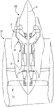
FIG. 1 provides a schematic illustration of an exemplary gas turbine engine embodiment according to the present disclosure;
FIG. 2 provides a cross-sectional view of an exemplary embodiment of a turbine vane and rotor blade airfoil according to the present disclosure;
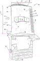
FIG. 3 provides an enlarged view of an exemplary airfoil embodiment according to the present disclosure;
FIG. 4 provides a cross-sectional view of an exemplary embodiment of the internal cooling passage illustrated in FIG. 3;
FIG. 5 provides a cross-sectional schematic view of one of the internal cooling passages taken through 5-5 in FIG. 4;
FIG. 6 provides an upstream perspective view of the internal cooling passage illustrated in FIG. 3;
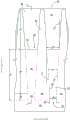
FIG. 7 provides an enlarged view of another exemplary airfoil embodiment according to the present disclosure;
FIG. 8 provides a cross-sectional view of an exemplary embodiment of the internal cooling passage illustrated in FIG. 7;
FIG. 9 provides a cross-sectional schematic view of one of the internal cooling passages taken through 9-9 in FIG. 8; and
FIG. 10 provides an upstream perspective view of the internal cooling passage illustrated in FIG. 9.
Parts list
10 engines
12 fan section
14 compressor
16 combustion stage
18 HP turbine stage
19 hot combustion gases
20 LP turbine stage
22 discharge stage
24 turbine vane
26 HP turbine blade
28 airfoil
30 platform
32 axial entry dovetail
34 supporting rotor disc
36 airfoil base
38 airfoil tip
40 pressurized air
42 pressure side wall
44 suction sidewall
46 leading edge
48 trailing edge
50 cooling cavity
51 coolant stream
52 Cooling passage
54 inlet
56 metering section
58 diffusion section
60 outflow orifice
62 interruption
64 cooling channel
66 bottom surface of the channel
68 axial spacer
70 upper passage surface
72 lower passage surface
74 internal pressure surface
76 internal suction surface
78 external pressure surface
80 breakout lip
82 shoulder
86 dividing wall
88 tail cone
Central engine axis A
S span/spanwise direction
Downstream direction D
W width/width direction
WP(cooling passage) width
WL(breakout lip) width
WMWidth of (metering section)
WD(diffusion section) width
WIWidth (import)
WB(interruption zone/outflow opening) width
Direction of C chord
Height H
HMHeight (of metering section)
HIHeight (of inlet)
HBHeight (of interruption zone)
HU(divergent mouth) height
Length of L
LO(cooling passage overall) length
LMLength of (metering section)
LD(diffusion zone) length
LS(cooling channel) length
Spread angle of theta 1 (diffusion section)
Theta 2 shoulder angle
R1 (metering) ratio
R2 (diffusion) ratio
R3 (lip) ratio
R4 (break) ratio.
Detailed Description
Reference will now be made in detail to present embodiments of the invention, one or more examples of which are illustrated in the accompanying drawings. The detailed description uses numerical and letter designations to refer to features in the drawings. Like or similar designations in the drawings and description have been used to refer to like or similar parts of the invention. Although reference may be made to one or more dimensions, ratios, or geometries illustrated in the corresponding figures, it should be understood that the figures are intended for illustrative purposes only and may not be drawn to scale.
As used herein, the terms "first," "second," and "third" may be used interchangeably to distinguish one component from another component, and are not intended to represent the position or importance of the individual components. The terms "upstream" and "downstream" refer to relative flow directions with respect to fluid flow in a fluid path. For example, "upstream" refers to the direction of flow from which the fluid flows, and "downstream" refers to the direction of flow to which the fluid flows.
The terms "at least one," "one or more," and/or "are open-ended expressions that are both conjunctive and disjunctive in operation. For example, each of the expressions "at least one of A, B and C", "at least one of A, B or C", "one or more of A, B and C", "A, B, or one or more of C" and "A, B, and/or C" means a alone, B alone, C alone, a and B together, a and C together, B and C together, or A, B and C together. As used herein, "substantially," "about," and "substantially" are relative terms that indicate that a desired value is approached as may be reasonably achieved within conventional manufacturing tolerances.
Referring now to the drawings, FIG. 1 is a schematic cross-sectional view of an exemplary high bypass turbofan type engine 10, referred to herein as a "turbofan 10," that may incorporate various embodiments of the present disclosure. Additionally, while an exemplary turbofan embodiment is shown, it is contemplated that the present disclosure may be equally applicable to other turbine-powered engines, such as open rotor, turbine shaft, or turboprop configurations.
As shown, the exemplary turbofan 10 of FIG. 1 extends along a central or centerline engine axis A and includes a fan system 12, a compressor 14, a combustion stage 16, a high pressure turbine stage 18, a low pressure turbine stage 20, and an exhaust stage 22. In operation, air flows through fan system 12 and is supplied to compressor 14. The compressed air is delivered from the compressor 14 to the combustion stages 16 where it is mixed with fuel and ignited to generate combustion gases. From the combustion stage 16, the combustion gases flow through the turbine stages 18, 20 and exit the gas turbine engine 10 via an exhaust 22. In other embodiments, gas turbine engine 10 may include any suitable number of fan systems, compressor systems, combustion systems, turbine systems, and/or discharge systems arranged in any suitable manner.
Illustrated in fig. 2 is an exemplary gas turbine engine high pressure turbine stage 18 circumscribed about a central engine axis a and positioned between a combustion stage 16 and a low pressure turbine stage 20 (see fig. 1). The high pressure turbine stage 18 includes a turbine nozzle having a circumferential row of turbine vanes 24, each vane formed as an airfoil 28. During operation, hot combustion gases 19 are discharged from the combustion stage 16 and through the row of vanes 24. The exemplary embodiment of the high pressure turbine 18 illustrated herein includes at least one row of circumferentially spaced apart high pressure turbine blades 26. Each of the turbine blades 26 includes an airfoil 28 secured to a platform 30 and an axial inlet dovetail 32 for mounting the turbine blade 26 on the perimeter of a supporting rotor disk 34.
Referring to FIG. 3, an exemplary airfoil 28 embodiment of the turbine blade 26 is illustrated. Although the illustrated airfoil 28 of FIG. 3 is shown as a turbine blade 26, it should be understood that the discussion of the airfoil 28 may be equally applicable to another gas turbine engine airfoil embodiment, such as a turbine vane 24 (see FIG. 2). As shown, the blade 26 extends radially outward along a span S from an airfoil base 36 on the blade platform 30 to an airfoil tip 38. During operation, hot combustion gases 19 are generated in the engine 10 and flow in the downstream direction D across the turbine airfoils 28, which turbine airfoils 28 extract energy from the hot combustion gases 19 for rotating the disks supporting the blades 26 for powering the compressor 14 (see fig. 1). A portion of the pressurized air 40 is suitably cooled and directed to the blades 26 for cooling thereof during operation.
In general, the airfoil 28 has a pair of oppositely configured sidewalls 42, 44 spaced apart in the width direction W. The pair of sidewalls 42, 44 includes a generally convex pressure sidewall 42 and a generally concave suction sidewall 44 extending longitudinally or radially outward along the span S from the airfoil base 36 to the airfoil tip 38. Sidewalls 42, 44 also extend axially in chordwise direction C between a leading edge 46 and a downstream trailing edge 48. The airfoil 28 is substantially hollow with the pressure and suction sidewalls 42, 44 defining an internal cooling cavity or circuit 50 therein for circulating a pressurized cooling air or coolant flow 51 during operation. In some exemplary embodiments, the pressurized cooling air or coolant flow 51 is from the portion of the pressurized air 40 that is diverted from the compressor 14 (see FIG. 1) to the turbine blades 26.
The airfoil 28 grows in width W, or widthwise, from the airfoil leading edge 46 to its maximum width aft thereof before converging to a relatively thin or pointed airfoil trailing edge 48. The size of the internal passage loop 50 thus varies with the width W of the airfoil 28 and is relatively thin directly forward of the trailing edge 48, where the two sidewalls 42, 44 are joined together and form a thin trailing edge 48 portion of the airfoil 28. One or more spanwise extending cooling passages 52 are provided at or near the trailing edge 48 of the airfoil 28 and facilitate airfoil cooling.
In certain embodiments, one or more portions of the airfoil 28 may be formed from a relatively low coefficient of thermal expansion material, including but not limited to a ceramic material and/or a coating on another substrate material. In some embodiments, the ceramic material is a matrix composite (CMC). For example, in the exemplary embodiment, suction sidewall 44 and pressure sidewall 42 are each formed from a CMC to define an interior cooling passage 52. Advantageously, this may increase the possible operating temperatures within the engine and allow for higher engine efficiencies to be achieved. Further, in some embodiments, advantageous geometries may be achieved without making the airfoil unsuitable for use in high temperature regions of a gas turbine engine.
Turning to the exemplary embodiment of fig. 4-6, a plurality of internal cooling passages 52 are provided and defined between the pressure and suction sidewalls 42, 44 in fluid communication with the cooling cavity 50 to direct the pressurized cooling air flow toward the downstream trailing edge 48. As shown, the plurality of cooling passages 52 are formed as a row of discrete components that extend chordwise and are spanwise spaced apart to define a height component H (e.g., maximum height) and a width component W (e.g., maximum width). Each cooling passage 52 is radially separated along the span S by a corresponding axial partition 68, the axial partition 68 extending in the chordwise direction C toward the trailing edge 48.
As illustrated in FIG. 4, each cooling passage extends in a chordwise direction C from cooling cavity 50 toward trailing edge 48. Further, each internal cooling passage 52 includes, in downstream series cooling flow relationship, an inlet 54, a metering section 56, and a spanwise diverging diffusion section 58 that opens into an exit orifice 60.
Generally, the inlet 54 communicates with the cooling passage 50 to receive the cooling flow 51 (see FIG. 3). Although a straight inlet 54 is illustrated herein, alternative embodiments may include another suitable converging or non-converging geometry (e.g., a constant angle of convergence mouth or a tail cone with a variable angle of convergence). The cooling air received at the inlet 58 is restricted from passing through the metering section 56 before expanding through the diffusion section 58.
After passing through the diffuser section 58, the outflow apertures 60 direct air across the cooling channels 64 toward the trailing edge 48. As shown, the channel 64 has a channel floor 66 that extends toward the trailing edge 48. Generally, the cooling channel 64 begins at the interruption 62 of the exit orifice 60 downstream of the diverging section 58. Alternatively, the cooling channels 64 may include channel floors 66, with the channel floors 66 being open and exposed to the hot combustion gases passing through the high pressure turbine (see also FIG. 5).
One or more heights H (e.g., maximum heights) of the cooling passages 52 are defined in the spanwise direction S between the upper and lower passage surfaces 70, 72. Each of the upper and lower passage surfaces 70, 72 is formed on an adjacent partition 68. The divider 68 may also be used to define a total passage length L in the chordwise direction CO. As shown, the total path length LOMay be defined between the inlet 54 and the discontinuity 62. As a result, the metering section 56, the diffusion section 58, and the cooling channel 64 each have a length L extending downstreamM、LDAnd LS. For example, length LO、LM、LDAnd LSMay each be the maximum length in the chordwise direction C.
In some embodiments, the metering section is formed between the inlet 54 and the diverging section 58 to have a constant height HM. Further, the metering section 56 may be defined between two substantially parallel segments in the chordwise direction C. In other words, the upper and lower passageway surfaces 70, 72 will be along the metering length LMSubstantially parallel. In an operating embodiment, the metering section 56 will define a constant cross-sectional area through which air may flow, e.g., HM*WM(see FIGS. 4 and 5).
In general, the diffusion section 58 may have a constant diffusion or expansion angle θ 1, the constant diffusion or expansion angle θ 1 configured to diffuse air flowing through the cooling passage 52. As shown, the spread angle θ 1 is defined between the metering section 56 and the outflow orifice 60 along an upper pathway surface 70 and a lower pathway surface 72. As a result, in some embodiments, the height H of the cooling passage 52 will be generally between the metering section 56 and the outflow aperture 60 along the chordwise direction C (i.e., along the diffusion length L)D) And is increased.
Alternatively, the expansion angle θ 1 may be defined relative to a chordwise direction C that is substantially parallel to the central engine axis A (see FIG. 2). In some embodiments, the angle of spread θ 1 may be substantially the same for each cooling passage 52. Certain embodiments of the spread angle θ 1 are defined as an angle between about 3 ° and about 15 °. Further embodiments of the spread angle θ 1 are defined as an angle of less than 5 °, between about 3 ° and about 5 °. Other embodiments of the expansion angle θ 1 are defined as angles greater than 11 °. Advantageously, the described angular geometry may allow for attached and stable coolant flow and/or reduce the likelihood of flow stall through the cooling passage 52. Further, the airfoils may be provided in a manner that may render them suitable for use in gas turbine engines without adversely affecting the structural integrity or durability of the airfoil trailing edge.
Turning to fig. 5, each cooling passage 52 defines one or more widths W (e.g., a maximum width) in the width direction. For example, the metering section 56 and the diverging section 58 (see FIG. 4) may each include a width component (W, respectively) between the interior surfaces 74, 76 of the pressure and suction sidewalls 42, 44MAnd WD). In some embodiments, the via width W is setPDefined as a constant value between the inner pressure surface 74 and the inner suction surface 76. In such an embodiment, the metering section width WMWill be equal to the diffusion section width WD。
While the cooling passages 52 may be formed in various suitable sizes, certain embodiments of the cooling passages 52 are formed to maintain one or more predetermined ratios within the passages. In some embodiments, this includes setting the metering length LMAnd a constant passage width W across the cooling passage 52PR1, i.e., R1 ═ LM/WP. Generally, the gauge length ratio is between about 2 and about 3.
Referring to FIGS. 4 and 5, and in additional or alternative embodiments, the cooling passage 52 may be formed to include a diffusion length L at the diffusion section 58DAnd a constant width W across the cooling passage 52PR2, i.e., R2 ═ LD/WP. Specifically, the diffusion ratio may be predetermined to be a ratio formed between about 4 and about 40. In some embodiments, the diffusion ratio is greater than 25, between about 25 and about 40. In selected embodiments, the diffusion ratio is between about 25 and about 35. In further embodiments, the diffusion ratio is about 32. Advantageously, these ratios R1, R2 may reduce the likelihood of flow stall and meter coldThe coolant flow 51 without adversely causing airfoil wear that may occur in existing airfoils.
At the discontinuity 62, the pressure sidewall 42 defines a discontinuity lip 80, the discontinuity lip 80 extending in the width direction W between the outer pressure surface 78 and the inner pressure surface 74. As a result, breakout lip 80 includes a width WLThe width WLDefining at least one side of the outflow orifice 60. The breakout lip 80 and the interior suction surface 76, together with the upper and lower passage surfaces 70, 72, define the outflow orifice 60. As a result, the outflow orifice 60 may include an orifice width W extending between the interior suction surface 76 and the lip 80B. As described above, the cooling passage width WPMay be substantially constant. In such an embodiment, the width W of the apertureBWill be set equal to the via width WP. In other words, the aperture width WBCan be matched with the width W of the viaPThe same is true.
Another predetermined ratio may be formed at the breakout aperture 60 between the breakout lip 80 and the width W of the cooling passage 52BIn the meantime. Alternative embodiments include an breakout lip width WLAnd cooling passage width WPI.e., R3 ═ W, of the predetermined lip R3 ratio, i.e., R3 ═ WL/WB. Specifically, in some embodiments, the predetermined lip ratio is less than 2, between about 0 and about 2. In further embodiments, the predetermined lip ratio is less than 1, between about 0.5 and about 1.0. In other further embodiments, the predetermined lip ratio is less than 0.5, between about 0 and about 0.5. The aforementioned lip ratio may facilitate advantageous film cooling without making the airfoil 28 unstable and unsuitable for high temperature operation.
As mentioned above, and illustrated with reference to fig. 4-6, some embodiments of the cooling passage 52 have a gap between the cooling cavity 50 and the outflow orifice 60 (i.e., along the total passage length L)O) Of a fixed or constant width WP. In such an embodiment, the width W of the diffuser section 58DAnd the width W of the metering section 56MAre all constant and equal. Further, the inlet 54 defines an inlet cross-sectional area, i.e., an inlet area cross-section, having a cross-gauge lengthLMSet inlet width W as a constant cross-sectional area extensionIAnd an inlet height HI. In other words, in some embodiments, the inlet width WIIs equal to the measurement width WMAnd an inlet height HIEqual to the measuring height HM。
As shown, in some embodiments, the internal pressure surface 74 and the internal suction surface 76 are each throughout the metering and diverging length LM、LDAnd the inner part is parallel. In some embodiments, the internal pressure surface 74 throughout the metering and diverging sections 56, 58 of the cooling passage 52 and their corresponding metering and diverging lengths LM、LDThe interior is flat or planar. Similarly, in additional or alternative embodiments, the internal suction surface 76 extends throughout the metering and diverging sections 56, 58 and their corresponding metering and diverging lengths LM、LDThe interior is flat or planar. Further, each cooling passage 52 may be substantially free of obstructions or branches. As a result, each cooling passage 52 may form a single unobstructed passage from the cooling cavity 50 to the outflow orifice 60. Additionally, each cooling channel 64 may be substantially free of obstructions to the airflow to the trailing edge 48.
In the illustrated embodiment of fig. 4-6, the channel floor 66 is coplanar with the interior suction surface 76 in the cooling passage 52. Alternatively, the transition between the interior suction surface 76 and the channel floor may be substantially smooth, without any steps or discontinuities. In additional or alternative embodiments, the inlet 54, metering section 56, and diffusion section 58 have the same passage width W in the embodiment of the internal cooling passage 52 as illustrated in FIG. 5P(i.e., of equal constant width).
As illustrated in fig. 6, the outflow orifice 60 includes an interrupted area cross-section defined in the width direction W and the span-wise direction S. Width W of the opening of the cross section of the interruption zoneBOr width, extends between the breakout lip 80 and the interior suction surface 76 at the outflow aperture 60. Height (or interruption height) H of the outflow opening in the spanwise direction SBExtending between the upper and lower passage surfaces 70, 72 at the outflow orifice 60.
Referring to FIGS. 4 to 6, in aIn some embodiments, the predetermined interruption ratio R4 may be formed between the interruption area and the inlet area, i.e., R4 ═ WB*HB)/(WI*HI). Alternatively, the interruption ratio may be configured to enhance the aerodynamic properties (e.g., prevent stall) of the coolant flow 51 (see FIG. 3) through the interior cooling passage 52 while limiting the air discharged at the outflow orifice 60. For example, some embodiments include an interruption ratio between about 1 and about 3 to advantageously expand the coolant flow 51. In further embodiments, the interruption ratio is less than 2.5. For example, the interrupt ratio of some embodiments is between about 1 and about 2. In still other embodiments, the interruption ratio is between about 0.5 and about 1.
As shown in FIGS. 4-6, some embodiments of the airfoil 28 include a plurality of shoulders 82, the plurality of shoulders 82 being disposed spanwise between adjacent cooling channels 64 and extending across the cooling channel length LS. Shoulder 82 may be integrally formed with suction sidewall 44 and/or partition 68 to extend in chordwise direction C. Additionally or alternatively, the shoulder may be integrally formed with the pressure sidewall 42. Generally, the shoulder 82 may extend across the channel floor 66 coplanar or flush with the outer pressure surface 78.
As shown in FIG. 4, certain embodiments of the shoulder 82 include one or more shoulder angles θ 2 relative to the chordwise direction C and parallel to the central engine axis A. Shoulder angle θ 2 may be substantially equal to or different than the expansion angle θ 1 of the diffuser section 58. Specifically, the shoulder angle may be between about 0 ° and about 15 °. In at least one embodiment, the shoulder angle is less than about 5 °. In another embodiment, the shoulder angle is about 0 ° (i.e., each shoulder 82 is substantially parallel to the other shoulders 82 in the chordwise direction C). In yet another embodiment, the shoulder angle is about 12 °.
As shown in FIG. 5, each shoulder 82 may taper to decrease in width as it extends from the interruption 62 toward the trailing edge 48. In certain embodiments, the shoulder 82 is formed to taper at a constant angle from a point substantially flush with the discontinuity 62 to a point substantially flush with the channel floor 66 at or near the trailing edge 48. Advantageously, the shoulder 82 may direct the airflow across the cooling channel 64, thereby improving the aerodynamic efficiency of the cooling airflow.
Turning to fig. 7 to 10, another set of exemplary embodiments of an airfoil is illustrated. It should be understood that the exemplary embodiment of fig. 7 to 10 is largely identical to the exemplary embodiment of fig. 3 to 6, except as otherwise noted. For example, the embodiment of fig. 7-10 includes an inlet 54, a metering section 56, and a diverging section 58 that are substantially similar in form and geometry to the inlet 54, metering section, and diverging section 58 described above.
However, the embodiment of fig. 7-10 does not include any of the shoulder structures discussed with reference to fig. 3-6. Instead, the airfoil 28 of fig. 7-10 provides a shoulderless cooling channel 64 in which the suction sidewall 44 extends from the outflow aperture 60 to the trailing edge 48 to define a shoulderless channel floor 66. As shown, the unobstructed channel floor 66 forms a common cooling channel 64 across the plurality of cooling passages 52. The channel floor 66 may remain flush with the internal suction surface 76, while the axial partition 68 may extend in the chordwise direction C along the cooling passage 52 until reaching the discontinuity 62. In some embodiments, the aft end of the divider 68 may form a divider wall 86, with the divider wall 86 being substantially flush with each discontinuity 62 in the spanwise direction S. Advantageously, the shoulderless configuration described may allow for greater airflow across the channel floor 66, thereby increasing heat dissipation. Furthermore, the shoulder-less embodiment described may provide such advantages without producing unstable aerodynamic losses.
As shown in fig. 8, the rear end of the partition 68 may form a partition wall 86. In certain shoulderless embodiments, the sweep tail cone 88 may be included as part of the aft end of the divider 68 between the diffuser section 58 and the outflow orifice 60. Optionally, the tail cone 88 may include a curved portion of the upper and/or lower access surfaces 70, 72. As a result, the diverging sweep tail cone 88 may include a mouth height HUHeight H of the mouthUIncreases non-linearly between the diverging section 58 and the discontinuity 62. The tail cone 88 may be configured to reduce aerodynamic losses due to flow separation wakes at the outflow apertures 60. The sweep tail cone 88 may also be configured to facilitate passage at the downstream end of the diverging section 58Interrupting the flow distribution of 62. In an alternative embodiment, the diverging section 58 maintains a constant angle θ 1 in the chordwise direction C until the outflow aperture 60 and/or the interruption 62 is reached.
This written description uses examples to disclose the invention, including the best mode, and also to enable any person skilled in the art to practice the invention, including making and using any devices or systems and performing any incorporated methods. The patentable scope of the invention is defined by the claims, and may include other examples that occur to those skilled in the art. Such other examples are intended to be within the scope of the claims if they have structural elements that do not differ from the literal language of the claims, or if they include equivalent structural elements with insubstantial differences from the literal languages of the claims.
Claims (8)
1. A ceramic airfoil, comprising:
a leading edge (46);
a trailing edge (48) positioned downstream of the leading edge (46) in a chordwise direction; and
a pair of sidewalls including a suction sidewall (44) and a pressure sidewall (42) spaced apart widthwise and extending chordally between the leading edge (46) and the trailing edge (48), the pair of sidewalls defining a cooling cavity (50) and a plurality of internal cooling passages (52) downstream of the cooling cavity (50) to receive a pressurized flow of cooling air, at least one internal cooling passage (52) of the plurality of internal cooling passages (52) being defined across a diffusion section (58) having a set diffusion length;
wherein the at least one internal cooling passage (52) comprises an inlet (54) upstream of the diffuser section (58) having a set inlet area cross-section, and wherein the pressure sidewall (42) comprises an interruption lip (80) at a set orifice width from the suction sidewall (44) to define an outflow orifice (60), the outflow orifice (60) comprising a set interruption area cross-section having an interruption ratio relative to the inlet area cross-section, wherein the diffusion ratio of diffusion length to orifice width is between 25 and 40, and wherein the interruption ratio is between 1 and 3.
2. The ceramic airfoil of claim 1, wherein the suction sidewall (44) extends from the outflow aperture (60) to the trailing edge (48) to define a channel floor (66), and wherein the airfoil further includes a plurality of shoulders (82), the plurality of shoulders (82) being disposed on the channel floor (66) between the outflow apertures (60) of the internal cooling passage (52).
3. The ceramic airfoil of claim 1, wherein the suction sidewall (44) extends from the exit aperture (60) to the trailing edge (48) to define a shoulderless channel floor.
4. The ceramic airfoil of claim 1, wherein the pressure sidewall (42) and the suction sidewall (44) include a ceramic matrix composite.
5. The ceramic airfoil of claim 1, wherein the diffusion section (58) includes a constant spread angle between 3 ° and 15 °.
6. The ceramic airfoil of claim 1, wherein the ceramic airfoil is configured within a gas turbine engine (10).
7. The ceramic airfoil of claim 1, further comprising a metered length ratio of metered length to orifice width, the metered length ratio being between 1 and 3.
8. A ceramic airfoil, comprising:
a leading edge (46);
a trailing edge (48) positioned downstream of the leading edge (46) in a chordwise direction; and
a pair of sidewalls including a suction sidewall (44) and a pressure sidewall spaced apart widthwise and extending chordally between the leading edge (46) and the trailing edge (48), the pair of sidewalls comprising a ceramic matrix composite and defining a cooling cavity (50) and a plurality of internal cooling passages (52) downstream of the cooling cavity (50) to receive a pressurized flow of cooling air, at least one internal cooling passage (52) defined across a diffusion section (58) having a set diffusion length;
wherein the pressure sidewall (42) includes an breakout lip (80) having a set lip width at a set orifice width from the suction sidewall (44), the breakout lip (80) having a lip width to orifice width lip ratio, the lip ratio being between 0 and 0.5.
Applications Claiming Priority (2)
| Application Number | Priority Date | Filing Date | Title |
|---|---|---|---|
| US14/990920 | 2016-01-08 | ||
| US14/990,920 US10301954B2 (en) | 2016-01-08 | 2016-01-08 | Turbine airfoil trailing edge cooling passage |
Publications (2)
| Publication Number | Publication Date |
|---|---|
| CN106968722A CN106968722A (en) | 2017-07-21 |
| CN106968722B true CN106968722B (en) | 2021-06-18 |
Family
ID=57708527
Family Applications (1)
| Application Number | Title | Priority Date | Filing Date |
|---|---|---|---|
| CN201710009807.5A Active CN106968722B (en) | 2016-01-08 | 2017-01-06 | Turbine airfoil trailing edge cooling passage |
Country Status (5)
| Country | Link |
|---|---|
| US (1) | US10301954B2 (en) |
| EP (1) | EP3190262A1 (en) |
| JP (1) | JP2017122451A (en) |
| CN (1) | CN106968722B (en) |
| CA (1) | CA2953594A1 (en) |
Families Citing this family (6)
| Publication number | Priority date | Publication date | Assignee | Title |
|---|---|---|---|---|
| US20180149085A1 (en) * | 2016-11-28 | 2018-05-31 | General Electric Company | Exhaust frame cooling via cooling flow reversal |
| US10697307B2 (en) * | 2018-01-19 | 2020-06-30 | Raytheon Technologies Corporation | Hybrid cooling schemes for airfoils of gas turbine engines |
| CN110925027A (en) * | 2019-11-29 | 2020-03-27 | 大连理工大学 | Turbine blade trailing edge tapered inclined exhaust split structure |
| US11215059B1 (en) * | 2020-09-03 | 2022-01-04 | Raytheon Technologies Corporation | Gas turbine engine airfoil with variable pitch cooling holes |
| US11603765B1 (en) * | 2021-07-16 | 2023-03-14 | Raytheon Technologies Corporation | Airfoil assembly with fiber-reinforced composite rings and toothed exit slot |
| US11549378B1 (en) | 2022-06-03 | 2023-01-10 | Raytheon Technologies Corporation | Airfoil assembly with composite rings and sealing shelf |
Citations (5)
| Publication number | Priority date | Publication date | Assignee | Title |
|---|---|---|---|---|
| US6241466B1 (en) * | 1999-06-01 | 2001-06-05 | General Electric Company | Turbine airfoil breakout cooling |
| US8096771B2 (en) * | 2008-09-25 | 2012-01-17 | Siemens Energy, Inc. | Trailing edge cooling slot configuration for a turbine airfoil |
| US20130302177A1 (en) * | 2012-05-08 | 2013-11-14 | Robert Frederick Bergholz, JR. | Turbine airfoil trailing edge bifurcated cooling holes |
| US20140003937A1 (en) * | 2012-06-30 | 2014-01-02 | General Electric Company | Component and a method of cooling a component |
| WO2014158277A2 (en) * | 2013-03-04 | 2014-10-02 | Freeman Ted J | Method for making gas turbine engine ceramic matrix composite airfoil |
Family Cites Families (7)
| Publication number | Priority date | Publication date | Assignee | Title |
|---|---|---|---|---|
| US8790084B2 (en) | 2011-10-31 | 2014-07-29 | General Electric Company | Airfoil and method of fabricating the same |
| US9175569B2 (en) | 2012-03-30 | 2015-11-03 | General Electric Company | Turbine airfoil trailing edge cooling slots |
| US20130302176A1 (en) | 2012-05-08 | 2013-11-14 | Robert Frederick Bergholz, JR. | Turbine airfoil trailing edge cooling slot |
| US20130302179A1 (en) | 2012-05-09 | 2013-11-14 | Robert Frederick Bergholz, JR. | Turbine airfoil trailing edge cooling hole plug and slot |
| US9145773B2 (en) | 2012-05-09 | 2015-09-29 | General Electric Company | Asymmetrically shaped trailing edge cooling holes |
| US9732617B2 (en) | 2013-11-26 | 2017-08-15 | General Electric Company | Cooled airfoil trailing edge and method of cooling the airfoil trailing edge |
| US9107026B1 (en) | 2014-07-18 | 2015-08-11 | Google Inc. | Range management with Bluetooth low energy |
-
2016
- 2016-01-08 US US14/990,920 patent/US10301954B2/en active Active
- 2016-12-22 JP JP2016248544A patent/JP2017122451A/en active Pending
-
2017
- 2017-01-03 EP EP17150186.9A patent/EP3190262A1/en not_active Withdrawn
- 2017-01-05 CA CA2953594A patent/CA2953594A1/en not_active Abandoned
- 2017-01-06 CN CN201710009807.5A patent/CN106968722B/en active Active
Patent Citations (5)
| Publication number | Priority date | Publication date | Assignee | Title |
|---|---|---|---|---|
| US6241466B1 (en) * | 1999-06-01 | 2001-06-05 | General Electric Company | Turbine airfoil breakout cooling |
| US8096771B2 (en) * | 2008-09-25 | 2012-01-17 | Siemens Energy, Inc. | Trailing edge cooling slot configuration for a turbine airfoil |
| US20130302177A1 (en) * | 2012-05-08 | 2013-11-14 | Robert Frederick Bergholz, JR. | Turbine airfoil trailing edge bifurcated cooling holes |
| US20140003937A1 (en) * | 2012-06-30 | 2014-01-02 | General Electric Company | Component and a method of cooling a component |
| WO2014158277A2 (en) * | 2013-03-04 | 2014-10-02 | Freeman Ted J | Method for making gas turbine engine ceramic matrix composite airfoil |
Also Published As
| Publication number | Publication date |
|---|---|
| JP2017122451A (en) | 2017-07-13 |
| US10301954B2 (en) | 2019-05-28 |
| CN106968722A (en) | 2017-07-21 |
| EP3190262A1 (en) | 2017-07-12 |
| CA2953594A1 (en) | 2017-07-08 |
| US20170198595A1 (en) | 2017-07-13 |
Similar Documents
| Publication | Publication Date | Title |
|---|---|---|
| CN106968722B (en) | Turbine airfoil trailing edge cooling passage | |
| JP4659206B2 (en) | Turbine nozzle with graded film cooling | |
| US9175569B2 (en) | Turbine airfoil trailing edge cooling slots | |
| US10253635B2 (en) | Blade tip cooling arrangement | |
| US10436040B2 (en) | Airfoil with dual-wall cooling for a gas turbine engine | |
| US7118326B2 (en) | Cooled gas turbine vane | |
| US20110236178A1 (en) | Branched airfoil core cooling arrangement | |
| US20170306764A1 (en) | Airfoil for a turbine engine | |
| US20060222496A1 (en) | Turbine nozzle with trailing edge convection and film cooling | |
| EP2568119B1 (en) | Airfoil for a gas turbine engine with an improved trailing edge cooling arrangement | |
| US10443396B2 (en) | Turbine component cooling holes | |
| US9017026B2 (en) | Turbine airfoil trailing edge cooling slots | |
| US20130302177A1 (en) | Turbine airfoil trailing edge bifurcated cooling holes | |
| JP2008157240A (en) | Aerofoil having improved cooling slot structure | |
| JP2015516539A (en) | Turbine airfoil trailing edge cooling slot | |
| US10794194B2 (en) | Staggered core printout | |
| US10677069B2 (en) | Component core with shaped edges | |
| US10662783B2 (en) | Variable heat transfer collector baffle | |
| EP3597857A1 (en) | Airfoil having angled trailing edge slots | |
| US11242758B2 (en) | Trailing edge insert for airfoil vane |
Legal Events
| Date | Code | Title | Description |
|---|---|---|---|
| PB01 | Publication | ||
| SE01 | Entry into force of request for substantive examination | ||
| SE01 | Entry into force of request for substantive examination | ||
| GR01 | Patent grant | ||
| GR01 | Patent grant |