EP1669544A1 - Turbine stage with film cooled fillet - Google Patents
Turbine stage with film cooled fillet Download PDFInfo
- Publication number
- EP1669544A1 EP1669544A1 EP05257613A EP05257613A EP1669544A1 EP 1669544 A1 EP1669544 A1 EP 1669544A1 EP 05257613 A EP05257613 A EP 05257613A EP 05257613 A EP05257613 A EP 05257613A EP 1669544 A1 EP1669544 A1 EP 1669544A1
- Authority
- EP
- European Patent Office
- Prior art keywords
- fillet
- airfoil
- turbine stage
- platform
- pressure
- Prior art date
- Legal status (The legal status is an assumption and is not a legal conclusion. Google has not performed a legal analysis and makes no representation as to the accuracy of the status listed.)
- Granted
Links
Images

Classifications
-
- F—MECHANICAL ENGINEERING; LIGHTING; HEATING; WEAPONS; BLASTING
- F01—MACHINES OR ENGINES IN GENERAL; ENGINE PLANTS IN GENERAL; STEAM ENGINES
- F01D—NON-POSITIVE DISPLACEMENT MACHINES OR ENGINES, e.g. STEAM TURBINES
- F01D5/00—Blades; Blade-carrying members; Heating, heat-insulating, cooling or antivibration means on the blades or the members
- F01D5/12—Blades
- F01D5/14—Form or construction
- F01D5/141—Shape, i.e. outer, aerodynamic form
- F01D5/142—Shape, i.e. outer, aerodynamic form of the blades of successive rotor or stator blade-rows
- F01D5/143—Contour of the outer or inner working fluid flow path wall, i.e. shroud or hub contour
-
- F—MECHANICAL ENGINEERING; LIGHTING; HEATING; WEAPONS; BLASTING
- F01—MACHINES OR ENGINES IN GENERAL; ENGINE PLANTS IN GENERAL; STEAM ENGINES
- F01D—NON-POSITIVE DISPLACEMENT MACHINES OR ENGINES, e.g. STEAM TURBINES
- F01D5/00—Blades; Blade-carrying members; Heating, heat-insulating, cooling or antivibration means on the blades or the members
- F01D5/12—Blades
- F01D5/14—Form or construction
- F01D5/18—Hollow blades, i.e. blades with cooling or heating channels or cavities; Heating, heat-insulating or cooling means on blades
- F01D5/186—Film cooling
-
- F—MECHANICAL ENGINEERING; LIGHTING; HEATING; WEAPONS; BLASTING
- F01—MACHINES OR ENGINES IN GENERAL; ENGINE PLANTS IN GENERAL; STEAM ENGINES
- F01D—NON-POSITIVE DISPLACEMENT MACHINES OR ENGINES, e.g. STEAM TURBINES
- F01D5/00—Blades; Blade-carrying members; Heating, heat-insulating, cooling or antivibration means on the blades or the members
- F01D5/12—Blades
- F01D5/14—Form or construction
- F01D5/18—Hollow blades, i.e. blades with cooling or heating channels or cavities; Heating, heat-insulating or cooling means on blades
- F01D5/187—Convection cooling
-
- F—MECHANICAL ENGINEERING; LIGHTING; HEATING; WEAPONS; BLASTING
- F05—INDEXING SCHEMES RELATING TO ENGINES OR PUMPS IN VARIOUS SUBCLASSES OF CLASSES F01-F04
- F05D—INDEXING SCHEME FOR ASPECTS RELATING TO NON-POSITIVE-DISPLACEMENT MACHINES OR ENGINES, GAS-TURBINES OR JET-PROPULSION PLANTS
- F05D2260/00—Function
- F05D2260/20—Heat transfer, e.g. cooling
- F05D2260/202—Heat transfer, e.g. cooling by film cooling
-
- Y—GENERAL TAGGING OF NEW TECHNOLOGICAL DEVELOPMENTS; GENERAL TAGGING OF CROSS-SECTIONAL TECHNOLOGIES SPANNING OVER SEVERAL SECTIONS OF THE IPC; TECHNICAL SUBJECTS COVERED BY FORMER USPC CROSS-REFERENCE ART COLLECTIONS [XRACs] AND DIGESTS
- Y02—TECHNOLOGIES OR APPLICATIONS FOR MITIGATION OR ADAPTATION AGAINST CLIMATE CHANGE
- Y02T—CLIMATE CHANGE MITIGATION TECHNOLOGIES RELATED TO TRANSPORTATION
- Y02T50/00—Aeronautics or air transport
- Y02T50/60—Efficient propulsion technologies, e.g. for aircraft
Definitions
- the present invention relates generally to gas turbine engines, and, more specifically, to turbines therein.
- air is pressurized in a compressor and mixed with fuel in a combustor for generating hot combustion gases.
- Turbine stages extract energy from the combustion gases to power the compressor, while also powering an upstream fan in a turbofan aircraft engine application, or powering an external drive shaft for marine and industrial applications.
- a high pressure turbine immediately follows the combustor and includes a stationary turbine nozzle which discharges combustion gases into a row of rotating first stage turbine rotor blades extending radially outwardly from a supporting rotor disk.
- the HPT may include one or more stages of rotor blades and corresponding turbine nozzles.
- LPT low pressure turbine
- Each turbine nozzle includes a row of stator vanes having radially outer and inner endwalls in the form of arcuate bands which support the vanes.
- the turbine rotor blades include airfoils integrally joined to radially inner endwalls or platforms supported in turn by corresponding dovetails which mount the individual blades in dovetail slots formed in the perimeter of the supporting rotor disk.
- An annular shroud surrounds the radially outer tips of the rotor airfoils in each turbine stage.
- stator vanes and rotor blades have corresponding airfoils including generally concave pressure sides and generally convex suction sides extending axially in chord between opposite leading and trailing edges. Adjacent vanes and adjacent blades form corresponding flow passages therebetween bound by the radially inner and outer endwalls.
- the combustion gases are discharged from the combustor and flow axially downstream through the respective flow passages defined between the stator vanes and rotor blades.
- the aerodynamic contours of the vanes and blades, and corresponding flow passages therebetween, are precisely configured for maximizing energy extraction from the combustion gases which in turn rotate the rotor from which the blades extend.
- the complex three-dimensional (3D) configuration of the vane and blade airfoils is tailored for maximizing efficiency of operation, and varies radially in span along the airfoils as well as axially along the chords of the airfoils between the leading and trailing edges. Accordingly, the velocity and pressure distributions of the combustion gases over the airfoil surfaces as well as within the corresponding flow passages also vary.
- Undesirable pressure losses in the combustion gas flowpaths therefore correspond with undesirable reduction in overall turbine efficiency.
- the combustion gases enter the corresponding rows of vanes and blades in the flow passages therebetween and are necessarily split at the respective leading edges of the airfoils.
- the locus of stagnation points of the incident combustion gases extends along the leading edge of each airfoil, and corresponding boundary layers are formed along the pressure and suction sides of each airfoil, as well as along each radially outer and inner endwall which collectively bound the four sides of each flow passage.
- the local velocity of the combustion gases varies from zero along the endwalls and airfoil surfaces to the unrestrained velocity in the combustion gases where the boundary layers terminate.
- the two vortices travel aft along the opposite pressure and suction sides of each airfoil and behave differently due to the different pressure and velocity distributions therealong.
- computational analysis indicates that the suction side vortex migrates away from the endwall toward the airfoil trailing edge and then interacts following the airfoil trailing edge with the pressure side vortex flowing aft thereto.
- a turbine stage includes a row of airfoils and their platforms spaced laterally apart to define flow passages therebetween.
- Each airfoil is integrally joined to its platform at a corresponding arcuate fillet which is larger along the pressure side of the airfoil and smaller along the suction side as it varies in size around the leading edge.
- a film cooling root hole is disposed in the root fillet in flow communication with an internal cooling circuit in the airfoil for discharging cooling air along the fillet for energizing boundary layer flow of combustion gases flowing through the flow passages during operation.
- Illustrated in Figure 1 are two exemplary first stage turbine rotor blades 10 which circumferentially adjoin each other in a full row thereof in a corresponding turbine stage of a gas turbine engine.
- combustion gases 12 are formed in a conventional combustor (not shown) and discharged in the axial downstream direction through the row of turbine blades 10 which extract energy therefrom for powering a supporting rotor disk (not shown) on which the blades are mounted.
- the turbine stage includes a complete row of the blades, with each blade having a corresponding airfoil 14 integrally joined at a root end to a corresponding radially inner endwall or platform 16. Each platform is in turn integrally joined to a corresponding axial-entry dovetail 18 conventionally configured for supporting the corresponding turbine blade in the perimeter of the rotor disk.
- Each airfoil includes a generally concave pressure side 20 and a circumferentially or laterally opposite, generally convex suction side 22 extending axially in chord between opposite leading and trailing edges 24,26. The two edges extend radially in span from root to tip of the airfoil.
- each airfoil is hollow and includes an internal cooling circuit 28 bound by the opposite pressure and suction sides.
- the cooling circuit may have any conventional configuration and includes inlet channels extending through the platform and dovetail for receiving cooling air 30 bled from the compressor of the engine (not shown).
- the cooling air is typically discharged from each airfoil through several rows of film cooling holes 32 located where desired on the pressure and suction sides of the airfoil, and typically concentrated near the leading edge thereof.
- Each airfoil typically also includes a row of trailing edge cooling holes 34 which emerge through the pressure side of the airfoil just before the thin trailing edge thereof.
- the exemplary turbine blades illustrated in Figures 1 and 2 may have any conventional configuration of the airfoil, platform, and dovetail for extracting energy from the combustion gases 12 during operation.
- the platform 16 is integrally joined to the root end of the airfoil and defines the radially inner flow boundary for the combustion gases 12.
- the blades are mounted in a row around the perimeter of the rotor blades, with the adjacent airfoils 14 being spaced circumferentially or laterally apart to define therebetween flow passages 36 for channeling the combustion gases 12 axially in the downstream direction during operation.
- Each inter-airfoil flow passage 36 in the turbine stage illustrated in Figures 1 and 2 is therefore defined and bounded by the pressure side 20 of one airfoil, the suction side 22 of the next adjacent airfoil, the corresponding pressure and suction side portions of the adjacent platforms 16, and the radially outer turbine shroud (not shown) which surrounds the radially outer tip ends of the airfoils in the complete row of turbine blades.
- combustion gases 12 flow through the corresponding flow passages 36 during operation and are necessarily split by the individual airfoils 14.
- the high velocity combustion gases are circumferentially split at the corresponding airfoil leading edges 24 with a stagnation pressure thereat, and with the formation of corresponding boundary layers along the opposite pressure and suction sides of the airfoil.
- combustion gases also form a boundary layer along the individual blade platforms 16 as the gases are split around the airfoil leading edge at its juncture with the platform.
- the split combustion gas flow along the blade platforms results in a pair of counterrotating horseshoe vortices which flow axially downstream through the flow passages along the opposite pressure and suction sides of each airfoil.
- These horseshoe vortices create turbulence in the boundary layers, and migrate radially outwardly toward the mid-span regions of the airfoils and create losses of total pressure and reduce turbine efficiency.
- each platform 16 is integrally joined to the root end of each airfoil at a relatively large arcuate fillet 38 specifically configured to change the contour of the endwall or platform 16 to improve aerodynamic efficiency.
- the fillet 38 preferably varies in size and configuration along the opposite sides of each airfoil. For example, the fillet 38 is larger along the airfoil pressure side 20 than along the suction side 22 around the leading edge 24, and changes or blends smaller in size around the leading edge.
- each of the fillets 38 includes a film cooling root or fillet hole 40 joined in flow communication with the internal cooling circuit 28 for discharging a portion of the spent cooling air 30 along the fillet during operation.
- the air discharged from the root hole 40 is used to energize the boundary layer flow of the combustion gases 12 at the initiation of the horseshoe vortices, and therefore weakens those vortices as they travel downstream through the corresponding flow passages 36.
- the configuration of the root fillet 38 and placement of the root holes 40 may be tailored specifically to decrease the adverse affects of the horseshoe vortices beginning at their inception at the airfoil leading edges.
- Figures 1-3 illustrate several views of the root fillet 38 which preferentially varies in size from the leading edge 24 to the trailing edge 26 of the airfoil along the opposite pressure and suction sides 20,22 thereof.
- the fillet 38 extends from the platform 16 greater or higher in radial span or elevation (+) on the pressure side 20 than on the suction side 22 near the leading edge 24.
- the fillet 38 may be defined by its radius of curvature in the circumferential direction and smoothly blends the junction of the root end of the airfoil with the platform in an arcuate profile.
- the fillet 38 is substantially larger in size or extent on the airfoil pressure side than on the suction side to correspond with the different pressure and velocity profiles of the combustion gases on the opposite sides of the airfoil.
- Figure 2 illustrates a circumferential section of the fillet 38.
- Figure 3 illustrate the axial profile of the fillet 38 on the pressure side 20 of the airfoil.
- Figure 4 is a top view of the fillet 38 schematically showing its variation in size and surface area in the platform 16 on the opposite sides of the individual airfoils 14.
- a conventional blade platform is a symmetrical surface revolution around the axial centerline axis of the engine or turbine rotor forming circular arcs.
- the root fillets 38 illustrated in Figures 2-4 blend with the outer surface of the platforms 16 and vary the surface contour thereof both circumferentially and axially.
- each fillet 38 blends in depth (-) in a local depression 42 in the exposed or outer surface of the platform 16 which depression is substantially larger on the pressure side 20 of the airfoil than on the suction side.
- the local depression illustrated in Figures 2-4 is relative to an otherwise conventional circumferentially circular platform having a reference or zero ( ⁇ ) radial elevation.
- the radial extent thereof may also be referenced from the forward and aft portions or edges of the flow platform which may remain axisymmetrical in the form of conventional circular arcs without local variation.
- the fillet 38 increases preferably continuously in depth from the pressure side 20 of the airfoil to the platform 16 on the suction side of the next adjacent airfoil just aft of the leading edge of the airfoil near the maximum thickness or hump region thereof as best illustrated in Figure 4.
- the platform depression 42 is bounded by the isocline of zero depth ( ⁇ ) and extends both axially in part and circumferentially in part, and terminates axially near the airfoil leading and trailing edges 24,26 corresponding with the forward and aft edges of the individual platform 16.
- the local depression 42 has a maximum depth in the platform axially between the leading and trailing edges of the airfoil in the midchord region of the airfoil, and along the lateral or circumferential edges or splitlines of the individual platforms where they adjoin each other in the row of blades.
- the local depressions 42 and bounding fillets 38 of adjacent airfoils 14 define a concave arcuate profile in the circumferential direction bounding the radially inner end of the common flow passage 36 defined circumferentially therebetween.
- Each turbine blade therefore has a fillet 38 and local depression 42 on its pressure side 20 which has a laterally concave arcuate profile, and a similar arcuate profile for the fillet and local depression on the opposite suction side 22, which are different in extent or surface area due to the twist angle of the airfoil extending diagonally across each of the quadrilateral platforms illustrated in Figure 4.
- the fillet 38 and depression 42 along the airfoil pressure side 20 are therefore circumferentially longer than the fillet 38 and depression along the suction side 22 of the adjacent airfoil.
- the local depression 42 in the platform of each blade is larger in surface area on the pressure side 20 than on the opposite suction side 22.
- the relatively large root fillets 38 and the cooperating local depressions 42 are specifically tailored in this region for weakening the vortices in conjunction with the introduction of the film cooling air from the root holes 40.
- Figures 1 and 4 illustrate the varying size of the fillet 38 as it decreases in size around the leading edge 24 from the pressure side 20 to the suction side 22.
- Figures 2 and 3 illustrate the depth (-) of the local depression 42 as it blends with the fillet 38. These figures also illustrate the increased elevation (+) of the fillet 38 as it blends with the root end of the airfoil.
- Figure 4 illustrates the exemplary elevation (+) and depression (-) of the fillet 38 and the depressions 42 as they vary in surface area and radial span or elevation between the leading and trailing edges of each airfoil and each platform.
- the fillet 38 as illustrated in Figures 1 and 4 experiences a large change in size around the leading edge 24 and gradually blends to the trailing edge of each airfoil along the opposite sides of the platform.
- the platform in turn, varies in surface depth to match the fillet 38 and blends with the forward and aft edges of the platform as illustrated in Figure 3, with a maximum depth axially therebetween.
- the relative size of the fillets 38 and local depressions 42 will vary in accordance with the specific design of the turbine stage, including the specific profile of the individual airfoils and their relative twist angle as mounted on the individual platform 16. However, since the horseshoe vortices begin at the airfoil leading edge, the introduction of the large fillet 38 around the junction of the leading edge with the platform may be used to advantage with the root holes 40 for significantly weakening the horseshoe vortices during operation.
- each root hole 40 may have a diameter in the exemplary range of 15-50 mils for injecting sufficient air into the fillet 38 to weaken in turn the horseshoe vortices.
- Figure 3 illustrates a preferred embodiment in which a pair of root holes 40 are located in each of the pressure and suction sides 20,22 of the airfoil on opposite sides of the leading edge 24 for injecting spent cooling air into the boundary layer of the combustion gas flow in the inter-blade flow passages.
- the fillets 38 are preferably devoid of any additional film cooling holes or apertures between the leading and trailing edges except near the leading edges 24 as indicated above.
- the fillets best cooperate with the introduction of air at the airfoil leading edges to weaken the horseshoe vortices at their inception since they increase in size and span as they travel downstream through the flow passages.
- the root holes 40 are limited in axial position in chord aft from the leading edge 24 to within about five diameters of the root holes themselves to ensure the introduction of cooling air to energize the boundary layer at the inception of the horseshoe vortices.
- the introduction of the large fillet around the airfoil leading edge blends the airfoil at its root with the platform and permits the introduction of the root holes 40 at this junction to preferentially inject spent cooling air to energize the boundary layer of the combustion gas flow at its inception along the blade platforms.
- the relatively large fillet 38 on the pressure side of the airfoil as illustrated in Figure 2 gradually slopes downwardly in the circumferential direction toward the suction side of the next adjacent blade along the flow streamline of the combustion gases.
- the pressure side horseshoe vortex combines with the injected film cooling air at the fillet 38 and travels downwardly toward the suction side of the next adjacent blade in the circumferential direction as it also flows downstream through the flow passage.
- the pressure side horseshoe vortex therefore is biased closer to the blade platform and reduces its tendency to migrate radially outwardly toward the midspan of the airfoil as it flows downstream through the flow passage.
- the local depressions 42 between adjacent airfoils smoothly blend with the aft edges of the platforms to control flow of the corresponding horseshoe vortices as they exit the flow passage.
- the root fillets 38, local platform depressions 42, and root holes 40 cooperate to create smaller horseshoe vortices from their inception which in turn will generate less flow turbulence.
- the vortices will remain closer to the blade platform and reduce their affect on the main passage flow. Total pressure losses will therefore be reduced for correspondingly increasing turbine efficiency.
- the heat transfer coefficient with the platforms will also be reduced for decreasing undesirable heating of the platforms themselves.
- weakening the horseshoe vortices can significantly reduce pressure losses and surface heating on the platform. And, film cooling from the root holes will also carry over to the platform surface for further insulating the platform from the hot combustion gases.
- the local depressions in the platforms on opposite sides of the airfoils lower the radially upward migration of the passage vortices and maintain the total pressure losses closer to the platforms to better protect the high velocity combustion gas main flow through the flow passages.
- root fillets 38, local depressions 42, and root holes 40 provide benefits in both aerodynamics and heat transfer and may be applied to other turbine stages, including turbine nozzles as well.
- the vane airfoils are integrally formed with radially outer and inner bands which define similar endwalls.
- the fillets, local depressions, and root holes may be advantageously introduced at both endwalls of each vane for weakening the corresponding horseshoe vortices as they are created.
Abstract
Description
- The present invention relates generally to gas turbine engines, and, more specifically, to turbines therein.
- In a gas turbine engine air is pressurized in a compressor and mixed with fuel in a combustor for generating hot combustion gases. Turbine stages extract energy from the combustion gases to power the compressor, while also powering an upstream fan in a turbofan aircraft engine application, or powering an external drive shaft for marine and industrial applications.
- A high pressure turbine (HPT) immediately follows the combustor and includes a stationary turbine nozzle which discharges combustion gases into a row of rotating first stage turbine rotor blades extending radially outwardly from a supporting rotor disk. The HPT may include one or more stages of rotor blades and corresponding turbine nozzles.
- Following the HPT is a low pressure turbine (LPT) which typically includes multiple stages of rotor blades and corresponding turbine nozzles.
- Each turbine nozzle includes a row of stator vanes having radially outer and inner endwalls in the form of arcuate bands which support the vanes. Correspondingly, the turbine rotor blades include airfoils integrally joined to radially inner endwalls or platforms supported in turn by corresponding dovetails which mount the individual blades in dovetail slots formed in the perimeter of the supporting rotor disk. An annular shroud surrounds the radially outer tips of the rotor airfoils in each turbine stage.
- The stator vanes and rotor blades have corresponding airfoils including generally concave pressure sides and generally convex suction sides extending axially in chord between opposite leading and trailing edges. Adjacent vanes and adjacent blades form corresponding flow passages therebetween bound by the radially inner and outer endwalls.
- During operation, the combustion gases are discharged from the combustor and flow axially downstream through the respective flow passages defined between the stator vanes and rotor blades. The aerodynamic contours of the vanes and blades, and corresponding flow passages therebetween, are precisely configured for maximizing energy extraction from the combustion gases which in turn rotate the rotor from which the blades extend.
- The complex three-dimensional (3D) configuration of the vane and blade airfoils is tailored for maximizing efficiency of operation, and varies radially in span along the airfoils as well as axially along the chords of the airfoils between the leading and trailing edges. Accordingly, the velocity and pressure distributions of the combustion gases over the airfoil surfaces as well as within the corresponding flow passages also vary.
- Undesirable pressure losses in the combustion gas flowpaths therefore correspond with undesirable reduction in overall turbine efficiency. For example, the combustion gases enter the corresponding rows of vanes and blades in the flow passages therebetween and are necessarily split at the respective leading edges of the airfoils.
- The locus of stagnation points of the incident combustion gases extends along the leading edge of each airfoil, and corresponding boundary layers are formed along the pressure and suction sides of each airfoil, as well as along each radially outer and inner endwall which collectively bound the four sides of each flow passage. In the boundary layers, the local velocity of the combustion gases varies from zero along the endwalls and airfoil surfaces to the unrestrained velocity in the combustion gases where the boundary layers terminate.
- One common source of turbine pressure losses is the formation of horseshoe vortices generated as the combustion gases are split in their travel around the airfoil leading edges. A total pressure gradient is effected in the boundary layer flow at the junction of the leading edge and endwalls of the airfoil. This pressure gradient at the airfoil leading edges forms a pair of counterrotating horseshoe vortices which travel downstream on the opposite sides of each airfoil near the endwall.
- The two vortices travel aft along the opposite pressure and suction sides of each airfoil and behave differently due to the different pressure and velocity distributions therealong. For example, computational analysis indicates that the suction side vortex migrates away from the endwall toward the airfoil trailing edge and then interacts following the airfoil trailing edge with the pressure side vortex flowing aft thereto.
- The interaction of the pressure and suction side vortices occurs near the midspan region of the airfoils and creates total pressure loss and a corresponding reduction in turbine efficiency. These vortices also create turbulence and increase undesirable heating of the endwalls.
- Since the horseshoe vortices are formed at the junctions of turbine rotor blades and their integral root platforms, as well at the junctions of nozzle stator vanes and their outer and inner bands, corresponding losses in turbine efficiency are created, as well as additional heating of the corresponding endwall components.
- Accordingly, it is desired to provide an improved turbine stage for reducing horseshoe vortex affects.
- According to the present invention, a turbine stage includes a row of airfoils and their platforms spaced laterally apart to define flow passages therebetween. Each airfoil is integrally joined to its platform at a corresponding arcuate fillet which is larger along the pressure side of the airfoil and smaller along the suction side as it varies in size around the leading edge. A film cooling root hole is disposed in the root fillet in flow communication with an internal cooling circuit in the airfoil for discharging cooling air along the fillet for energizing boundary layer flow of combustion gases flowing through the flow passages during operation.
- The invention, in accordance with preferred and exemplary embodiments, together with further objects and advantages thereof, is more particularly described in the following detailed description taken in conjunction with the accompanying drawings in which:
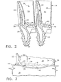
- Figure 1 is an isometric view of two adjacent rotor blades in the first stage of a high pressure turbine.
- Figure 2 is an elevational sectional view through the turbine blades illustrated in Figure 1 and taken along line 2-2.
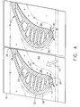
- Figure 3 is an enlarged side elevational view of the platform region at the root of the airfoil pressure side of one of the blades illustrated in Figure 1 and taken along line 3-3. Figure 4 is a partly sectional planiform view of the two blades illustrated in Figure 1 and taken along line 4-4.
- Illustrated in Figure 1 are two exemplary first stage
turbine rotor blades 10 which circumferentially adjoin each other in a full row thereof in a corresponding turbine stage of a gas turbine engine. As indicated above,combustion gases 12 are formed in a conventional combustor (not shown) and discharged in the axial downstream direction through the row ofturbine blades 10 which extract energy therefrom for powering a supporting rotor disk (not shown) on which the blades are mounted. - The turbine stage includes a complete row of the blades, with each blade having a
corresponding airfoil 14 integrally joined at a root end to a corresponding radially inner endwall orplatform 16. Each platform is in turn integrally joined to a corresponding axial-entry dovetail 18 conventionally configured for supporting the corresponding turbine blade in the perimeter of the rotor disk. - Each airfoil includes a generally
concave pressure side 20 and a circumferentially or laterally opposite, generally convexsuction side 22 extending axially in chord between opposite leading andtrailing edges - As shown in Figures 1 and 2, each airfoil is hollow and includes an
internal cooling circuit 28 bound by the opposite pressure and suction sides. The cooling circuit may have any conventional configuration and includes inlet channels extending through the platform and dovetail for receivingcooling air 30 bled from the compressor of the engine (not shown). - The cooling air is typically discharged from each airfoil through several rows of
film cooling holes 32 located where desired on the pressure and suction sides of the airfoil, and typically concentrated near the leading edge thereof. Each airfoil typically also includes a row of trailingedge cooling holes 34 which emerge through the pressure side of the airfoil just before the thin trailing edge thereof. - The exemplary turbine blades illustrated in Figures 1 and 2 may have any conventional configuration of the airfoil, platform, and dovetail for extracting energy from the
combustion gases 12 during operation. As indicated above, theplatform 16 is integrally joined to the root end of the airfoil and defines the radially inner flow boundary for thecombustion gases 12. - The blades are mounted in a row around the perimeter of the rotor blades, with the
adjacent airfoils 14 being spaced circumferentially or laterally apart to definetherebetween flow passages 36 for channeling thecombustion gases 12 axially in the downstream direction during operation. - Each
inter-airfoil flow passage 36 in the turbine stage illustrated in Figures 1 and 2 is therefore defined and bounded by thepressure side 20 of one airfoil, thesuction side 22 of the next adjacent airfoil, the corresponding pressure and suction side portions of theadjacent platforms 16, and the radially outer turbine shroud (not shown) which surrounds the radially outer tip ends of the airfoils in the complete row of turbine blades. - As indicated above in the Background section, the
combustion gases 12 flow through thecorresponding flow passages 36 during operation and are necessarily split by theindividual airfoils 14. The high velocity combustion gases are circumferentially split at the correspondingairfoil leading edges 24 with a stagnation pressure thereat, and with the formation of corresponding boundary layers along the opposite pressure and suction sides of the airfoil. - Furthermore, the combustion gases also form a boundary layer along the
individual blade platforms 16 as the gases are split around the airfoil leading edge at its juncture with the platform. - Accordingly, the split combustion gas flow along the blade platforms results in a pair of counterrotating horseshoe vortices which flow axially downstream through the flow passages along the opposite pressure and suction sides of each airfoil. These horseshoe vortices create turbulence in the boundary layers, and migrate radially outwardly toward the mid-span regions of the airfoils and create losses of total pressure and reduce turbine efficiency.
- In order to reduce these adverse affects of the horseshoe vortices, each
platform 16 is integrally joined to the root end of each airfoil at a relatively largearcuate fillet 38 specifically configured to change the contour of the endwall orplatform 16 to improve aerodynamic efficiency. Since the pressure and suction sides of the airfoil are differently configured for effecting the corresponding pressure and velocity distributions thereover, thefillet 38 preferably varies in size and configuration along the opposite sides of each airfoil. For example, thefillet 38 is larger along theairfoil pressure side 20 than along thesuction side 22 around the leadingedge 24, and changes or blends smaller in size around the leading edge. - Furthermore, each of the
fillets 38 includes a film cooling root orfillet hole 40 joined in flow communication with theinternal cooling circuit 28 for discharging a portion of the spent coolingair 30 along the fillet during operation. The air discharged from theroot hole 40 is used to energize the boundary layer flow of thecombustion gases 12 at the initiation of the horseshoe vortices, and therefore weakens those vortices as they travel downstream through thecorresponding flow passages 36. The configuration of theroot fillet 38 and placement of theroot holes 40 may be tailored specifically to decrease the adverse affects of the horseshoe vortices beginning at their inception at the airfoil leading edges. - Figures 1-3 illustrate several views of the
root fillet 38 which preferentially varies in size from the leadingedge 24 to thetrailing edge 26 of the airfoil along the opposite pressure andsuction sides fillet 38 extends from theplatform 16 greater or higher in radial span or elevation (+) on thepressure side 20 than on thesuction side 22 near the leadingedge 24. - The
fillet 38 may be defined by its radius of curvature in the circumferential direction and smoothly blends the junction of the root end of the airfoil with the platform in an arcuate profile. Thefillet 38 is substantially larger in size or extent on the airfoil pressure side than on the suction side to correspond with the different pressure and velocity profiles of the combustion gases on the opposite sides of the airfoil. - Figure 2 illustrates a circumferential section of the
fillet 38. Figure 3 illustrate the axial profile of thefillet 38 on thepressure side 20 of the airfoil. And, Figure 4 is a top view of thefillet 38 schematically showing its variation in size and surface area in theplatform 16 on the opposite sides of theindividual airfoils 14. - A conventional blade platform is a symmetrical surface revolution around the axial centerline axis of the engine or turbine rotor forming circular arcs. In contrast, the
root fillets 38 illustrated in Figures 2-4 blend with the outer surface of theplatforms 16 and vary the surface contour thereof both circumferentially and axially. - For example, each
fillet 38 blends in depth (-) in alocal depression 42 in the exposed or outer surface of theplatform 16 which depression is substantially larger on thepressure side 20 of the airfoil than on the suction side. The local depression illustrated in Figures 2-4 is relative to an otherwise conventional circumferentially circular platform having a reference or zero (θ) radial elevation. - Furthermore, since the introduction of the
large fillets 38 anddepressions 42 are local effects, the radial extent thereof may also be referenced from the forward and aft portions or edges of the flow platform which may remain axisymmetrical in the form of conventional circular arcs without local variation. - As shown in -Figure 2, for example, the
fillet 38 increases preferably continuously in depth from thepressure side 20 of the airfoil to theplatform 16 on the suction side of the next adjacent airfoil just aft of the leading edge of the airfoil near the maximum thickness or hump region thereof as best illustrated in Figure 4. - As shown in Figures 3 and 4, the
platform depression 42 is bounded by the isocline of zero depth (θ) and extends both axially in part and circumferentially in part, and terminates axially near the airfoil leading and trailingedges individual platform 16. Thelocal depression 42 has a maximum depth in the platform axially between the leading and trailing edges of the airfoil in the midchord region of the airfoil, and along the lateral or circumferential edges or splitlines of the individual platforms where they adjoin each other in the row of blades. - In the exemplary embodiment illustrated in Figure 2, the
local depressions 42 and boundingfillets 38 ofadjacent airfoils 14 define a concave arcuate profile in the circumferential direction bounding the radially inner end of thecommon flow passage 36 defined circumferentially therebetween. Each turbine blade therefore has afillet 38 andlocal depression 42 on itspressure side 20 which has a laterally concave arcuate profile, and a similar arcuate profile for the fillet and local depression on theopposite suction side 22, which are different in extent or surface area due to the twist angle of the airfoil extending diagonally across each of the quadrilateral platforms illustrated in Figure 4. - As best shown in Figures 2 and 4, the
fillet 38 anddepression 42 along theairfoil pressure side 20 are therefore circumferentially longer than thefillet 38 and depression along thesuction side 22 of the adjacent airfoil. Correspondingly, thelocal depression 42 in the platform of each blade is larger in surface area on thepressure side 20 than on theopposite suction side 22. - Since the horseshoe vortices are initiated at the forward end of the individual blade platforms at the junction with the leading
edge 24, the relativelylarge root fillets 38 and the cooperatinglocal depressions 42 are specifically tailored in this region for weakening the vortices in conjunction with the introduction of the film cooling air from the root holes 40. - Figures 1 and 4 illustrate the varying size of the
fillet 38 as it decreases in size around the leadingedge 24 from thepressure side 20 to thesuction side 22. Figures 2 and 3 illustrate the depth (-) of thelocal depression 42 as it blends with thefillet 38. These figures also illustrate the increased elevation (+) of thefillet 38 as it blends with the root end of the airfoil. - Figure 4 illustrates the exemplary elevation (+) and depression (-) of the
fillet 38 and thedepressions 42 as they vary in surface area and radial span or elevation between the leading and trailing edges of each airfoil and each platform. - The
fillet 38 as illustrated in Figures 1 and 4 experiences a large change in size around the leadingedge 24 and gradually blends to the trailing edge of each airfoil along the opposite sides of the platform. The platform, in turn, varies in surface depth to match thefillet 38 and blends with the forward and aft edges of the platform as illustrated in Figure 3, with a maximum depth axially therebetween. - The relative size of the
fillets 38 andlocal depressions 42 will vary in accordance with the specific design of the turbine stage, including the specific profile of the individual airfoils and their relative twist angle as mounted on theindividual platform 16. However, since the horseshoe vortices begin at the airfoil leading edge, the introduction of thelarge fillet 38 around the junction of the leading edge with the platform may be used to advantage with the root holes 40 for significantly weakening the horseshoe vortices during operation. - Although a
single root hole 40 could be used in thefillet 38 on either or both sides of the leadingedge 24, in the preferred embodiment illustrated in Figure 3 a plurality of the root holes 40 border each of theleading edges 24 on the pressure andsuction sides fillet 38 to weaken in turn the horseshoe vortices. - For example, Figure 3 illustrates a preferred embodiment in which a pair of root holes 40 are located in each of the pressure and
suction sides edge 24 for injecting spent cooling air into the boundary layer of the combustion gas flow in the inter-blade flow passages. - Correspondingly, the
fillets 38 are preferably devoid of any additional film cooling holes or apertures between the leading and trailing edges except near the leadingedges 24 as indicated above. The fillets best cooperate with the introduction of air at the airfoil leading edges to weaken the horseshoe vortices at their inception since they increase in size and span as they travel downstream through the flow passages. - In the preferred embodiment illustrated in the several Figures, the root holes 40 are limited in axial position in chord aft from the leading
edge 24 to within about five diameters of the root holes themselves to ensure the introduction of cooling air to energize the boundary layer at the inception of the horseshoe vortices. - The introduction of the large fillet around the airfoil leading edge blends the airfoil at its root with the platform and permits the introduction of the root holes 40 at this junction to preferentially inject spent cooling air to energize the boundary layer of the combustion gas flow at its inception along the blade platforms. The relatively
large fillet 38 on the pressure side of the airfoil as illustrated in Figure 2 gradually slopes downwardly in the circumferential direction toward the suction side of the next adjacent blade along the flow streamline of the combustion gases. - Accordingly, the pressure side horseshoe vortex combines with the injected film cooling air at the
fillet 38 and travels downwardly toward the suction side of the next adjacent blade in the circumferential direction as it also flows downstream through the flow passage. The pressure side horseshoe vortex therefore is biased closer to the blade platform and reduces its tendency to migrate radially outwardly toward the midspan of the airfoil as it flows downstream through the flow passage. - As illustrated in Figure 4, the
local depressions 42 between adjacent airfoils smoothly blend with the aft edges of the platforms to control flow of the corresponding horseshoe vortices as they exit the flow passage. - The
root fillets 38,local platform depressions 42, and root holes 40 cooperate to create smaller horseshoe vortices from their inception which in turn will generate less flow turbulence. The vortices will remain closer to the blade platform and reduce their affect on the main passage flow. Total pressure losses will therefore be reduced for correspondingly increasing turbine efficiency. Furthermore, by reducing turbulence of the horseshoe vortices, the heat transfer coefficient with the platforms will also be reduced for decreasing undesirable heating of the platforms themselves. - Accordingly, weakening the horseshoe vortices can significantly reduce pressure losses and surface heating on the platform. And, film cooling from the root holes will also carry over to the platform surface for further insulating the platform from the hot combustion gases. The local depressions in the platforms on opposite sides of the airfoils lower the radially upward migration of the passage vortices and maintain the total pressure losses closer to the platforms to better protect the high velocity combustion gas main flow through the flow passages.
- The introduction of the
root fillets 38,local depressions 42, and root holes 40 provide benefits in both aerodynamics and heat transfer and may be applied to other turbine stages, including turbine nozzles as well. In a turbine nozzle, the vane airfoils are integrally formed with radially outer and inner bands which define similar endwalls. The fillets, local depressions, and root holes may be advantageously introduced at both endwalls of each vane for weakening the corresponding horseshoe vortices as they are created.
Claims (10)
- A turbine stage comprising:a row of airfoils (14) integrally joined to corresponding platforms (16) and spaced laterally apart to define respective flow passages (36) therebetween for channeling combustion gases (12);each of said airfoils (14) including a concave pressure side (20) and a laterally opposite convex suction side (22) bounding an internal cooling circuit (28), and extending in chord between opposite leading and trailing edges (24,26);each of said airfoils (14) blending with said platforms (16) in an arcuate fillet (38) being larger in size along said pressure side (20) than along said suction side (22) around said leading edge (24), and forming a local depression (42) in said platform being larger on said pressure side (20) than on said suction side (22); andeach of said fillets (38) including a film cooling root hole (40) joined in flow communication with said cooling circuit (28) for discharging cooling air (30) along said fillet for energizing boundary layer flow of said combustion gases (12) and weakening horseshoe vortices in said flow passages (36).
- A turbine stage according to claim 1 wherein said fillet (38) varies in radius between said leading and trailing edges (24,26), and extends from said platform (16) greater in span on said pressure side (20) than on suction side (22) near said leading edge (24).
- A turbine stage according to claim 2 wherein said fillet (38) on said airfoil pressure side (20) increases in depth in said depression (42) to the platform (16) on the suction side (22) of an adjacent airfoil (14).
- A turbine stage according to claim 3 wherein said platform depression (42) terminates near said airfoil leading and trailing edges (24,26).
- A turbine stage according to claim 4 wherein said fillet (38) and depressions (42) in said platform (16) on said pressure and suction sides (20,22) of said airfoil have laterally concave arcuate profiles.
- A turbine stage according to claim 5 wherein said fillet (38) and depression (42) along said airfoil pressure side (20) are circumferentially longer than said fillet (38) and depression (42) along said suction side (22).
- A turbine stage according to claim 6 further comprising a plurality of said root holes (42) bordering each of said leading edges (24) on said pressure and suction sides (20,22).
- A turbine stage according to claim 6 further comprising a pair of said root holes (40) in each of said pressure and suction sides (20,22) of each of said airfoils adjacent said leading edges (24) thereof.
- A turbine stage according to claim 6 wherein said fillets (38) are devoid of apertures except near said leading edges (24).
- A turbine stage according to claim 6 wherein said root hole (40) is disposed within about five diameters in chord from said leading edge (24).
Applications Claiming Priority (1)
| Application Number | Priority Date | Filing Date | Title |
|---|---|---|---|
| US11/010,688 US7217096B2 (en) | 2004-12-13 | 2004-12-13 | Fillet energized turbine stage |
Publications (2)
| Publication Number | Publication Date |
|---|---|
| EP1669544A1 true EP1669544A1 (en) | 2006-06-14 |
| EP1669544B1 EP1669544B1 (en) | 2014-02-26 |
Family
ID=35985460
Family Applications (1)
| Application Number | Title | Priority Date | Filing Date |
|---|---|---|---|
| EP05257613.9A Expired - Fee Related EP1669544B1 (en) | 2004-12-13 | 2005-12-12 | Turbine stage with film cooled fillet |
Country Status (3)
| Country | Link |
|---|---|
| US (1) | US7217096B2 (en) |
| EP (1) | EP1669544B1 (en) |
| JP (1) | JP4785511B2 (en) |
Cited By (12)
| Publication number | Priority date | Publication date | Assignee | Title |
|---|---|---|---|---|
| EP1688587A3 (en) * | 2005-01-10 | 2007-05-02 | General Electric Company | Funnel fillet turbine stage |
| EP1795707A2 (en) * | 2005-12-08 | 2007-06-13 | The General Electric Company | Leading edge fillet for gas turbine engine nozzle . |
| EP2093382A2 (en) * | 2008-02-20 | 2009-08-26 | United Technologies Corporation | Stator vane having a fanned cooling hole array on a large fillet between airfoil and platform |
| FR2928173A1 (en) * | 2008-02-28 | 2009-09-04 | Snecma Sa | DAWN WITH 3D PLATFORM COMPRISING A BULB INTERAUBES. |
| WO2010074930A1 (en) * | 2008-12-24 | 2010-07-01 | General Electric Company | Curved platform turbine blade |
| CN102052091A (en) * | 2009-10-28 | 2011-05-11 | 通用电气公司 | Turbine airfoil-sidewall integration |
| WO2011115731A1 (en) * | 2010-03-15 | 2011-09-22 | Siemens Energy, Inc. | Airfoil having built-up surface with embedded cooling passage |
| US8128365B2 (en) | 2007-07-09 | 2012-03-06 | Siemens Energy, Inc. | Turbine airfoil cooling system with rotor impingement cooling |
| EP2918779A1 (en) | 2014-03-11 | 2015-09-16 | Siemens Aktiengesellschaft | Turbine blade |
| EP3118412A1 (en) * | 2015-07-06 | 2017-01-18 | United Technologies Corporation | Method for generating an airfoil including an aerodynamically-shaped fillet and airfoils including the aerodynamically-shaped fillet |
| EP2252770B1 (en) * | 2008-02-28 | 2017-10-04 | Snecma | Blade with non-axisymmetric platform |
| CN107420133A (en) * | 2016-05-24 | 2017-12-01 | 通用电气公司 | Cooling duct for gas turbine system rotor blade |
Families Citing this family (45)
| Publication number | Priority date | Publication date | Assignee | Title |
|---|---|---|---|---|
| US7220100B2 (en) * | 2005-04-14 | 2007-05-22 | General Electric Company | Crescentic ramp turbine stage |
| US7887297B2 (en) * | 2006-05-02 | 2011-02-15 | United Technologies Corporation | Airfoil array with an endwall protrusion and components of the array |
| US8366399B2 (en) * | 2006-05-02 | 2013-02-05 | United Technologies Corporation | Blade or vane with a laterally enlarged base |
| US8511978B2 (en) * | 2006-05-02 | 2013-08-20 | United Technologies Corporation | Airfoil array with an endwall depression and components of the array |
| GB0704426D0 (en) * | 2007-03-08 | 2007-04-18 | Rolls Royce Plc | Aerofoil members for a turbomachine |
| US7621718B1 (en) * | 2007-03-28 | 2009-11-24 | Florida Turbine Technologies, Inc. | Turbine vane with leading edge fillet region impingement cooling |
| US7775769B1 (en) | 2007-05-24 | 2010-08-17 | Florida Turbine Technologies, Inc. | Turbine airfoil fillet region cooling |
| US7836703B2 (en) * | 2007-06-20 | 2010-11-23 | General Electric Company | Reciprocal cooled turbine nozzle |
| US8571604B2 (en) * | 2008-01-18 | 2013-10-29 | Hewlett-Packard Development Company, L.P. | Subscriber identity module (SIM) card access system and method |
| US8057178B2 (en) * | 2008-09-04 | 2011-11-15 | General Electric Company | Turbine bucket for a turbomachine and method of reducing bow wave effects at a turbine bucket |
| US8647067B2 (en) * | 2008-12-09 | 2014-02-11 | General Electric Company | Banked platform turbine blade |
| US8727725B1 (en) * | 2009-01-22 | 2014-05-20 | Florida Turbine Technologies, Inc. | Turbine vane with leading edge fillet region cooling |
| EP2248996B1 (en) * | 2009-05-04 | 2014-01-01 | Alstom Technology Ltd | Gas turbine |
| US20100284800A1 (en) * | 2009-05-11 | 2010-11-11 | General Electric Company | Turbine nozzle with sidewall cooling plenum |
| US8727726B2 (en) * | 2009-08-11 | 2014-05-20 | General Electric Company | Turbine endwall cooling arrangement |
| US8439643B2 (en) * | 2009-08-20 | 2013-05-14 | General Electric Company | Biformal platform turbine blade |
| CN103052765B (en) | 2011-03-11 | 2015-11-25 | 三菱日立电力系统株式会社 | Gas turbine bucket and combustion gas turbine |
| WO2012140806A1 (en) | 2011-04-14 | 2012-10-18 | 三菱重工業株式会社 | Gas turbine rotor blade and gas turbine |
| WO2012144244A1 (en) | 2011-04-22 | 2012-10-26 | 三菱重工業株式会社 | Vane member and rotary machine |
| US9017030B2 (en) | 2011-10-25 | 2015-04-28 | Siemens Energy, Inc. | Turbine component including airfoil with contour |
| US9194235B2 (en) * | 2011-11-25 | 2015-11-24 | Mtu Aero Engines Gmbh | Blading |
| EP2650475B1 (en) * | 2012-04-13 | 2015-09-16 | MTU Aero Engines AG | Blade for a flow device, blade assembly and flow device |
| US9033669B2 (en) * | 2012-06-15 | 2015-05-19 | General Electric Company | Rotating airfoil component with platform having a recessed surface region therein |
| US9267386B2 (en) | 2012-06-29 | 2016-02-23 | United Technologies Corporation | Fairing assembly |
| US9091180B2 (en) | 2012-07-19 | 2015-07-28 | Siemens Energy, Inc. | Airfoil assembly including vortex reducing at an airfoil leading edge |
| EP2885506B8 (en) | 2012-08-17 | 2021-03-31 | Raytheon Technologies Corporation | Contoured flowpath surface |
| US20140154068A1 (en) * | 2012-09-28 | 2014-06-05 | United Technologies Corporation | Endwall Controuring |
| WO2014105102A1 (en) | 2012-12-28 | 2014-07-03 | United Technologies Corporation | Platform with curved edges adjacent suction side of airfoil |
| US9297257B2 (en) | 2013-01-31 | 2016-03-29 | General Electric Company | Spinner assembly with removable fan blade leading edge fairings |
| WO2014130214A1 (en) * | 2013-02-22 | 2014-08-28 | United Technologies Corporation | Stator vane assembly and method therefore |
| EP2971521B1 (en) | 2013-03-11 | 2022-06-22 | Rolls-Royce Corporation | Gas turbine engine flow path geometry |
| WO2014197062A2 (en) | 2013-03-15 | 2014-12-11 | United Technologies Corporation | Fan exit guide vane platform contouring |
| EP3158167B1 (en) | 2014-06-18 | 2020-10-07 | Siemens Energy, Inc. | End wall configuration for gas turbine engine |
| JP2016040463A (en) * | 2014-08-13 | 2016-03-24 | 株式会社Ihi | Axial flow type turbo machine |
| US20170009589A1 (en) * | 2015-07-09 | 2017-01-12 | Siemens Energy, Inc. | Gas turbine engine blade with increased wall thickness zone in the trailing edge-hub region |
| US10196904B2 (en) | 2016-01-24 | 2019-02-05 | Rolls-Royce North American Technologies Inc. | Turbine endwall and tip cooling for dual wall airfoils |
| US10577955B2 (en) | 2017-06-29 | 2020-03-03 | General Electric Company | Airfoil assembly with a scalloped flow surface |
| JP6943706B2 (en) * | 2017-09-22 | 2021-10-06 | 三菱パワー株式会社 | Turbine blades and gas turbines |
| KR20190046118A (en) * | 2017-10-25 | 2019-05-07 | 두산중공업 주식회사 | Turbine Blade |
| US20210040855A1 (en) * | 2018-02-15 | 2021-02-11 | Siemens Aktiengesellschaft | Assembly of turbine blades and corresponding article of manufacture |
| US20190264569A1 (en) * | 2018-02-23 | 2019-08-29 | General Electric Company | Turbine rotor blade with exiting hole to deliver fluid to boundary layer film |
| DE102018212178A1 (en) * | 2018-07-23 | 2020-01-23 | MTU Aero Engines AG | Gas turbine blade arrangement |
| BE1026579B1 (en) * | 2018-08-31 | 2020-03-30 | Safran Aero Boosters Sa | PROTUBERANCE VANE FOR TURBOMACHINE COMPRESSOR |
| US20210079799A1 (en) * | 2019-09-12 | 2021-03-18 | General Electric Company | Nozzle assembly for turbine engine |
| CN114278388A (en) * | 2021-12-24 | 2022-04-05 | 上海电气燃气轮机有限公司 | Gas film cooling structure of turbine blade |
Citations (7)
| Publication number | Priority date | Publication date | Assignee | Title |
|---|---|---|---|---|
| GB2253443A (en) * | 1991-03-05 | 1992-09-09 | Rolls Royce Plc | Gas turbine nozzle guide vane arrangement |
| WO1996000841A1 (en) * | 1993-06-14 | 1996-01-11 | United Technologies Corporation | Flow directing assembly for the compression section of a rotary machine |
| US6017186A (en) * | 1996-12-06 | 2000-01-25 | Mtu-Motoren-Und Turbinen-Union Muenchen Gmbh | Rotary turbomachine having a transonic compressor stage |
| WO2000061918A2 (en) * | 1999-03-22 | 2000-10-19 | Siemens Westinghouse Power Corporation | Airfoil leading edge vortex elimination device |
| EP1126135A2 (en) * | 2000-02-18 | 2001-08-22 | General Electric Company | Ceramic turbine airfoils with cooled trailing edge blocks |
| EP1239116A2 (en) * | 2001-03-07 | 2002-09-11 | General Electric Company | Fluted blisk |
| US20040081548A1 (en) * | 2002-10-23 | 2004-04-29 | Zess Gary A. | Flow directing device |
Family Cites Families (22)
| Publication number | Priority date | Publication date | Assignee | Title |
|---|---|---|---|---|
| CH229266A (en) | 1942-03-26 | 1943-10-15 | Sulzer Ag | Turbomachine, the blade surfaces of which merge into the base surface with a rounding at the blade root. |
| FR1602965A (en) | 1968-08-16 | 1971-03-01 | ||
| US4194869A (en) | 1978-06-29 | 1980-03-25 | United Technologies Corporation | Stator vane cluster |
| ZA8234B (en) | 1981-01-05 | 1982-11-24 | Alsthom Atlantique | A turbine stage |
| JPS5832903A (en) | 1981-08-20 | 1983-02-26 | Toshiba Corp | Axial flow turbine |
| JPS59101504A (en) * | 1982-11-18 | 1984-06-12 | ベ−・ベ−・ツエ−・アクチエンゲゼルシヤフト・ブラウン・ボヴエリ・ウント・コンパニイ | Gas turbine blade apparatus |
| US5382135A (en) | 1992-11-24 | 1995-01-17 | United Technologies Corporation | Rotor blade with cooled integral platform |
| US5340278A (en) | 1992-11-24 | 1994-08-23 | United Technologies Corporation | Rotor blade with integral platform and a fillet cooling passage |
| JP3316418B2 (en) | 1997-06-12 | 2002-08-19 | 三菱重工業株式会社 | Gas turbine cooling blade |
| GB9823840D0 (en) | 1998-10-30 | 1998-12-23 | Rolls Royce Plc | Bladed ducting for turbomachinery |
| US6419446B1 (en) | 1999-08-05 | 2002-07-16 | United Technologies Corporation | Apparatus and method for inhibiting radial transfer of core gas flow within a core gas flow path of a gas turbine engine |
| US6511294B1 (en) | 1999-09-23 | 2003-01-28 | General Electric Company | Reduced-stress compressor blisk flowpath |
| US6561761B1 (en) * | 2000-02-18 | 2003-05-13 | General Electric Company | Fluted compressor flowpath |
| US6338609B1 (en) | 2000-02-18 | 2002-01-15 | General Electric Company | Convex compressor casing |
| JP2001271602A (en) | 2000-03-27 | 2001-10-05 | Honda Motor Co Ltd | Gas turbine engine |
| US6354797B1 (en) | 2000-07-27 | 2002-03-12 | General Electric Company | Brazeless fillet turbine nozzle |
| US6341939B1 (en) * | 2000-07-31 | 2002-01-29 | General Electric Company | Tandem cooling turbine blade |
| EP1207268B1 (en) * | 2000-11-16 | 2005-02-09 | Siemens Aktiengesellschaft | Gas turbine blade and a process for manufacturing a gas turbine blade |
| JP4508432B2 (en) * | 2001-01-09 | 2010-07-21 | 三菱重工業株式会社 | Gas turbine cooling structure |
| US6669445B2 (en) | 2002-03-07 | 2003-12-30 | United Technologies Corporation | Endwall shape for use in turbomachinery |
| US6884029B2 (en) * | 2002-09-26 | 2005-04-26 | Siemens Westinghouse Power Corporation | Heat-tolerated vortex-disrupting fluid guide component |
| US6830432B1 (en) * | 2003-06-24 | 2004-12-14 | Siemens Westinghouse Power Corporation | Cooling of combustion turbine airfoil fillets |
-
2004
- 2004-12-13 US US11/010,688 patent/US7217096B2/en active Active
-
2005
- 2005-12-02 JP JP2005348577A patent/JP4785511B2/en not_active Expired - Fee Related
- 2005-12-12 EP EP05257613.9A patent/EP1669544B1/en not_active Expired - Fee Related
Patent Citations (7)
| Publication number | Priority date | Publication date | Assignee | Title |
|---|---|---|---|---|
| GB2253443A (en) * | 1991-03-05 | 1992-09-09 | Rolls Royce Plc | Gas turbine nozzle guide vane arrangement |
| WO1996000841A1 (en) * | 1993-06-14 | 1996-01-11 | United Technologies Corporation | Flow directing assembly for the compression section of a rotary machine |
| US6017186A (en) * | 1996-12-06 | 2000-01-25 | Mtu-Motoren-Und Turbinen-Union Muenchen Gmbh | Rotary turbomachine having a transonic compressor stage |
| WO2000061918A2 (en) * | 1999-03-22 | 2000-10-19 | Siemens Westinghouse Power Corporation | Airfoil leading edge vortex elimination device |
| EP1126135A2 (en) * | 2000-02-18 | 2001-08-22 | General Electric Company | Ceramic turbine airfoils with cooled trailing edge blocks |
| EP1239116A2 (en) * | 2001-03-07 | 2002-09-11 | General Electric Company | Fluted blisk |
| US20040081548A1 (en) * | 2002-10-23 | 2004-04-29 | Zess Gary A. | Flow directing device |
Cited By (19)
| Publication number | Priority date | Publication date | Assignee | Title |
|---|---|---|---|---|
| EP1688587A3 (en) * | 2005-01-10 | 2007-05-02 | General Electric Company | Funnel fillet turbine stage |
| EP1795707A3 (en) * | 2005-12-08 | 2011-12-07 | General Electric Company | Leading edge fillet for gas turbine engine nozzle . |
| EP1795707A2 (en) * | 2005-12-08 | 2007-06-13 | The General Electric Company | Leading edge fillet for gas turbine engine nozzle . |
| US8128365B2 (en) | 2007-07-09 | 2012-03-06 | Siemens Energy, Inc. | Turbine airfoil cooling system with rotor impingement cooling |
| EP2093382A2 (en) * | 2008-02-20 | 2009-08-26 | United Technologies Corporation | Stator vane having a fanned cooling hole array on a large fillet between airfoil and platform |
| EP2093382A3 (en) * | 2008-02-20 | 2012-04-18 | United Technologies Corporation | Stator vane having a fanned cooling hole array on a large fillet between airfoil and platform |
| WO2009112774A3 (en) * | 2008-02-28 | 2009-10-29 | Snecma | Blade with 3d platform comprising an inter-blade bulb |
| FR2928173A1 (en) * | 2008-02-28 | 2009-09-04 | Snecma Sa | DAWN WITH 3D PLATFORM COMPRISING A BULB INTERAUBES. |
| US9518467B2 (en) | 2008-02-28 | 2016-12-13 | Snecma | Blade with 3D platform comprising an inter-blade bulb |
| EP2252770B1 (en) * | 2008-02-28 | 2017-10-04 | Snecma | Blade with non-axisymmetric platform |
| WO2010074930A1 (en) * | 2008-12-24 | 2010-07-01 | General Electric Company | Curved platform turbine blade |
| US8459956B2 (en) | 2008-12-24 | 2013-06-11 | General Electric Company | Curved platform turbine blade |
| CN102052091A (en) * | 2009-10-28 | 2011-05-11 | 通用电气公司 | Turbine airfoil-sidewall integration |
| WO2011115731A1 (en) * | 2010-03-15 | 2011-09-22 | Siemens Energy, Inc. | Airfoil having built-up surface with embedded cooling passage |
| CN102802866A (en) * | 2010-03-15 | 2012-11-28 | 西门子能量股份有限公司 | Airfoil having built-up surface with embedded cooling passage |
| US9630277B2 (en) | 2010-03-15 | 2017-04-25 | Siemens Energy, Inc. | Airfoil having built-up surface with embedded cooling passage |
| EP2918779A1 (en) | 2014-03-11 | 2015-09-16 | Siemens Aktiengesellschaft | Turbine blade |
| EP3118412A1 (en) * | 2015-07-06 | 2017-01-18 | United Technologies Corporation | Method for generating an airfoil including an aerodynamically-shaped fillet and airfoils including the aerodynamically-shaped fillet |
| CN107420133A (en) * | 2016-05-24 | 2017-12-01 | 通用电气公司 | Cooling duct for gas turbine system rotor blade |
Also Published As
| Publication number | Publication date |
|---|---|
| JP2006170198A (en) | 2006-06-29 |
| US20060127220A1 (en) | 2006-06-15 |
| JP4785511B2 (en) | 2011-10-05 |
| EP1669544B1 (en) | 2014-02-26 |
| US7217096B2 (en) | 2007-05-15 |
Similar Documents
| Publication | Publication Date | Title |
|---|---|---|
| EP1669544B1 (en) | Turbine stage with film cooled fillet | |
| EP1688587B1 (en) | Funnel fillet turbine stage | |
| US7134842B2 (en) | Scalloped surface turbine stage | |
| AU2013201301B2 (en) | Scalloped surface turbine stage with purge trough | |
| US7220100B2 (en) | Crescentic ramp turbine stage | |
| EP3205820B1 (en) | End wall contour for an axial flow turbine stage | |
| EP2642075B1 (en) | Turbine stage and corresponding turbine blade having a scalloped platform | |
| US8206115B2 (en) | Scalloped surface turbine stage with trailing edge ridges | |
| US8459956B2 (en) | Curved platform turbine blade | |
| CA2548168C (en) | Turbine airfoil with variable and compound fillet | |
| EP2423444A2 (en) | Turbine nozzle with contoured band | |
| EP1326005A2 (en) | Step-down turbine platform | |
| Lee et al. | Crescentic ramp turbine stage |
Legal Events
| Date | Code | Title | Description |
|---|---|---|---|
| PUAI | Public reference made under article 153(3) epc to a published international application that has entered the european phase |
Free format text: ORIGINAL CODE: 0009012 |
|
| AK | Designated contracting states |
Kind code of ref document: A1 Designated state(s): AT BE BG CH CY CZ DE DK EE ES FI FR GB GR HU IE IS IT LI LT LU LV MC NL PL PT RO SE SI SK TR |
|
| AX | Request for extension of the european patent |
Extension state: AL BA HR MK YU |
|
| 17P | Request for examination filed |
Effective date: 20061214 |
|
| 17Q | First examination report despatched |
Effective date: 20070116 |
|
| AKX | Designation fees paid |
Designated state(s): DE FR GB |
|
| RAP1 | Party data changed (applicant data changed or rights of an application transferred) |
Owner name: GENERAL ELECTRIC COMPANY |
|
| GRAP | Despatch of communication of intention to grant a patent |
Free format text: ORIGINAL CODE: EPIDOSNIGR1 |
|
| INTG | Intention to grant announced |
Effective date: 20130801 |
|
| GRAS | Grant fee paid |
Free format text: ORIGINAL CODE: EPIDOSNIGR3 |
|
| GRAA | (expected) grant |
Free format text: ORIGINAL CODE: 0009210 |
|
| AK | Designated contracting states |
Kind code of ref document: B1 Designated state(s): DE FR GB |
|
| REG | Reference to a national code |
Ref country code: GB Ref legal event code: FG4D |
|
| REG | Reference to a national code |
Ref country code: DE Ref legal event code: R096 Ref document number: 602005042754 Country of ref document: DE Effective date: 20140410 |
|
| REG | Reference to a national code |
Ref country code: DE Ref legal event code: R097 Ref document number: 602005042754 Country of ref document: DE |
|
| PLBE | No opposition filed within time limit |
Free format text: ORIGINAL CODE: 0009261 |
|
| STAA | Information on the status of an ep patent application or granted ep patent |
Free format text: STATUS: NO OPPOSITION FILED WITHIN TIME LIMIT |
|
| 26N | No opposition filed |
Effective date: 20141127 |
|
| REG | Reference to a national code |
Ref country code: DE Ref legal event code: R097 Ref document number: 602005042754 Country of ref document: DE Effective date: 20141127 |
|
| REG | Reference to a national code |
Ref country code: FR Ref legal event code: PLFP Year of fee payment: 11 |
|
| REG | Reference to a national code |
Ref country code: FR Ref legal event code: PLFP Year of fee payment: 12 |
|
| PGFP | Annual fee paid to national office [announced via postgrant information from national office to epo] |
Ref country code: GB Payment date: 20161228 Year of fee payment: 12 |
|
| PGFP | Annual fee paid to national office [announced via postgrant information from national office to epo] |
Ref country code: FR Payment date: 20161227 Year of fee payment: 12 |
|
| PGFP | Annual fee paid to national office [announced via postgrant information from national office to epo] |
Ref country code: DE Payment date: 20161229 Year of fee payment: 12 |
|
| REG | Reference to a national code |
Ref country code: DE Ref legal event code: R119 Ref document number: 602005042754 Country of ref document: DE |
|
| GBPC | Gb: european patent ceased through non-payment of renewal fee |
Effective date: 20171212 |
|
| REG | Reference to a national code |
Ref country code: FR Ref legal event code: ST Effective date: 20180831 |
|
| PG25 | Lapsed in a contracting state [announced via postgrant information from national office to epo] |
Ref country code: FR Free format text: LAPSE BECAUSE OF NON-PAYMENT OF DUE FEES Effective date: 20180102 Ref country code: DE Free format text: LAPSE BECAUSE OF NON-PAYMENT OF DUE FEES Effective date: 20180703 |
|
| PG25 | Lapsed in a contracting state [announced via postgrant information from national office to epo] |
Ref country code: GB Free format text: LAPSE BECAUSE OF NON-PAYMENT OF DUE FEES Effective date: 20171212 |